Article

Research on SOC Estimation of Lithium-Ion Battery Based on CA-SVDUKF Algorithm

School of Mechanical Engineering, Shanghai DianJi University, Shanghai 201306, China
*
Author to whom correspondence should be addressed.
Batteries 2025, 11(12), 435; https://doi.org/10.3390/batteries11120435
Submission received: 17 October 2025 / Revised: 13 November 2025 / Accepted: 20 November 2025 / Published: 25 November 2025
(This article belongs to the Special Issue Control, Modelling, and Management of Batteries)

Abstract

Because of the problem that the traditional unscented Kalman filter algorithm (UKF) may terminate the iteration due to the non-positive definite error covariance matrix during state of charge (SOC) estimation of lithium-ion battery, considering the unknown noise and current mutation during the actual operation of the battery, an SOC estimation method based on covariance adaptive singular value decomposition unscented Kalman filter (CA-SVDUKF) algorithm was proposed. Based on the singular value decomposition traceless Kalman filtering algorithm, the proposed CA-SVDUKF algorithm introduced an adaptive method of covariance matching to improve the algorithm’s anti-interference capability to unknown noise. Accordingly, an error covariance matrix adaptive method with adaptive scaling factor was proposed, which could reduce the influence of current mutation exerting on the estimated convergence rate. Taking the lithium-ion battery as the research object, the second-order RC equivalent circuit model of the lithium-ion battery was first built, and then the online parameters of the battery were identified. Finally, the CA-SVDUKF algorithm was used to complete the SOC estimation. The algorithm was simulated and verified under three working conditions: ordinary pulse condition, DST working condition, and US06 working condition. The experimental results showed that the algorithm had higher accuracy and stability compared with the traditional extended Kalman filter algorithm (EKF) and the UKF algorithm. The maximum absolute error was less than 0.6%, and the root mean square error was less than 0.3%, which could verify the effectiveness and superiority of the algorithm.

1. Introduction

The vigorous development of electric vehicles (EVs) is a key measure for achieving the “dual-carbon” strategy. However, the driving range and safety of EVs remain major factors hindering their widespread adoption. The battery management system (BMS) ensures the safe and reliable operation of batteries and EVs, among which state of charge (SOC) estimation is a critical and challenging research focus [1]. Accurate SOC estimation enables drivers to clearly understand the remaining battery capacity, thereby maintaining the battery within an appropriate SOC range, facilitating rational planning of charging, discharging, and operating schedules [2]. Moreover, precise SOC estimation is of great significance for extending battery lifetime, optimizing the battery system, and ensuring the safe operation of EVs.
SOC cannot be directly measured but must instead be inferred from measurable quantities such as voltage and current, and it is typically expressed as a percentage [3]. Existing SOC estimation methods can be classified into four categories: ampere-hour integration, look-up table methods, data-driven approaches, and model-based methods. The ampere-hour integration method may accumulate errors when the initial SOC is unknown [4]. In addition, battery aging and temperature variations can cause deviations in rated capacity and coulombic efficiency, thereby reducing estimation accuracy. The look-up table method estimates SOC by mapping characteristic parameters, such as open-circuit voltage (OCV), electrochemical impedance spectrum, and internal resistance, to SOC, offering a simple and intuitive approach [5]. However, its primary drawback lies in the requirement for long rest periods to stabilize internal electrochemical reactions, which limits the accuracy of measured parameters. Consequently, this method is unsuitable for online and high-precision SOC estimation. Commonly used data-driven methods include neural networks (NN), fuzzy logic, genetic algorithms (GAs), and support vector machines (SVM) [6]. Although these methods do not require the construction of an accurate equivalent battery model, their main disadvantages are high computational cost, long processing time, and strong dependence of estimation accuracy on the quality and quantity of training data [7]. Model-based methods generally employ filtering algorithms, such as Kalman filters, particle filters, and H∞ filters [8]. Among these, Kalman filter-based approaches are widely adopted due to their simplicity and relatively high accuracy. To address the limited estimation accuracy of the extended Kalman filter (EKF)—which neglects higher-order terms beyond the second order in the Taylor expansion—Gao Jin et al. [9] proposed an unscented Kalman filter (UKF)-based SOC estimation strategy, showing improved accuracy in simulations compared with EKF. Further, An Zhiguo et al. [10] integrated the Sage–Husa adaptive filtering algorithm with UKF to develop an adaptive UKF (AUKF), which demonstrated enhanced accuracy and adaptability. Similarly, Zou Lin et al. [11] proposed a dual unscented Kalman filter (DUKF) for parameter identification and SOC estimation, with experimental results confirming improved accuracy and stability compared with the standard UKF. Nevertheless, conventional EKF suffers from low accuracy due to the omission of higher-order terms, and UKF may encounter non-positive definite error covariance matrices, leading to algorithm termination. Deng et al. [12] proposed a lithium-ion battery SOC estimation algorithm based on the forgetting factor recursive least squares (FFRLS) method, the Thevenin equivalent circuit model, and singular value decomposition–unscented Kalman filter (SVD-UKF). This method aims to overcome the linearization error of the Kalman filter and the shortcomings of the non-positive definite covariance matrix. Dhanagare et al. [13] used a third-order resistance-capacitance equivalent circuit model to simulate the dynamic behavior of lithium-ion batteries. The parameters of this model were estimated using the extended Kalman filter, and a recurrent neural network model using long short-term memory networks was introduced to estimate the SOC and health status. Xing et al. [14] proposed a joint fractional-order multi-innovation unscented Kalman filter (FOUKF-FOMIUKF) algorithm for online prediction of the battery’s SOC. This method uses the fractional-order unscented Kalman filter to online identify the parameters of the model and then transmits these parameters to the fractional function sequential multi-innovation unscented Kalman filter to calculate the SOC of the battery. Wang et al. [15] proposed the LM-IEKF algorithm, which can effectively estimate the SOC of lithium-ion batteries, especially suitable for the estimation of electric vehicles. This method uses the Levenberg–Marquardt method to optimize the error covariance matrix of IKEF. Li et al. [16] to reduce the influence of noise on the estimation of the battery’s SOC, a covariance matching link was introduced, and the adaptive extended Kalman filter (AEKF) algorithm was used to estimate the electric SOC. Son et al. [17] proposed a physics-informed dual-stage network for lithium-ion battery SOC estimation under various aging and temperature conditions, integrating physical knowledge with deep learning to enhance robustness. Wu et al. [18] developed a BiLSTM model constrained by physical rules to improve SOC estimation accuracy under external pressure and thermal variations.
In summary, current SOC estimation research emphasizes accuracy and stability. In this study, a second-order RC equivalent circuit model of the battery is established, and model parameters are identified using the forgetting-factor recursive least squares (FFRLS) method. Since UKF provides higher accuracy than EKF, this paper designs the SOC estimation algorithm based on UKF. To address the issue of non-positive definite error covariance matrices that may cause UKF iteration failure, singular value decomposition (SVD) is introduced to replace Cholesky decomposition. Furthermore, because the prior statistical characteristics of noise in real EV operation are typically unknown, a covariance matching technique is incorporated to enhance the algorithm’s robustness against disturbances. Considering that sudden current variations frequently occur during practical battery operation, an adaptive error covariance matrix adjustment method with a scaling factor is also proposed to improve algorithm stability. Based on the above analysis, this paper proposes a covariance-adaptive SVD-UKF (CA-SVDUKF) approach for SOC estimation. The accuracy and stability of the proposed method are validated under three operating conditions: standard pulse condition, dynamic stress test (DST), and US06 condition.

2. Development of the Lithium-Ion Battery Equivalent Model

2.1. Second-Order RC Equivalent Circuit Model

Commonly used battery models include electrochemical models, data-driven models, and equivalent circuit models. Among them, electrochemical models exhibit high complexity and pose significant challenges for parameter identification, making them rarely employed in practical applications. Data-driven models require large amounts of experimental data to train and generally suffer from long computation times, which limit their real-time applicability. In contrast, equivalent circuit models achieve relatively high accuracy with simpler modeling procedures and more convenient parameter identification, and thus are widely adopted in battery modeling and state estimation. An n-order RC equivalent circuit model typically consists of two or more RC networks to characterize the dynamic and static behaviors of the battery. Increasing the number of RC networks improves model accuracy, but simultaneously increases the difficulty of parameter identification. When the number of RC networks exceeds three, the computational burden grows rapidly while the accuracy improvement remains marginal [19]. Considering the trade-off between computational accuracy and model complexity, this study employs a second-order RC equivalent circuit model as the battery model. The structure of the second-order RC equivalent circuit model is illustrated in Figure 1.
In this figure, U o c represents the open-circuit voltage of the battery, and R 0 denotes the ohmic internal resistance. R 1 and C 1 correspond to the electrochemical polarization resistance and capacitance, respectively, which are used to model the electrochemical polarization process during charging and discharging. Similarly, R 2 and C 2 represent the concentration polarization resistance and capacitance, respectively, which are used to model the concentration polarization process during charging and discharging. U 1 denotes the voltage across the parallel branch of R 1 and C 1 , while U 2 denotes the voltage across the parallel branch of R 2 and C 2 . I represents the circuit current, and U L denotes the terminal voltage. In this study, the discharge current direction is defined as positive, whereas the charging current direction is defined as negative.

2.2. State-Space Equations of the Battery

According to Kirchhoff’s laws in circuit theory, the mathematical expressions of the model in Figure 1 can be derived as follows:
I = C 1 d U 1 d t + U 1 R 1 I = C 2 d U 2 d t + U 2 R 2 U L = U o c I R 0 U 1 U 2
According to the definition of S O C , the calculation formula of S O C during discharge can be expressed as follows:
S O C = 1 Δ t I ( k ) d t Q N × 100 %
Equation (2) can be discretized as follows:
S O C ( k + 1 ) = S O C ( k ) Δ t I ( k ) Q N
By selecting S O C , U 1 , and U 2 as the state variables, solving and discretizing the equations in (1), and combining them with Equation (3), the state-space equations of the battery can be obtained.
State equations:
x k + 1 = f x k , u k + w k = S O C ( k + 1 ) U 1 ( k + 1 ) U 2 ( k + 1 ) = 1 0 0 0 e Δ t R 1 C 1 0 0 0 e Δ t R 2 C 2 S O C ( k ) U 1 ( k ) U 2 ( k ) + Δ t Q N R 1 1 e Δ t R 1 C 1 R 2 1 e Δ t R 2 C 2 I ( k ) + w k
Observation equations:
y k = g x k , u k + v k = U L ( k ) = U o c ( S O C ( k ) ) U 1 ( k ) U 2 ( k ) R 0 I ( k ) + v k
x k = S O C ( k ) U 1 ( k ) U 2 ( k ) ,   A k = 1 0 0 0 e Δ t R 1 C 1 0 0 0 e Δ t R 2 C 2 ,   B k = Δ t Q N R 1 1 e Δ t R 1 C 1 R 2 1 e Δ t R 2 C 2 .
where x k represents the state variables, S O C ( k ) denotes the SOC of the lithium-ion battery at time step k , U 1 ( k ) represents the electrochemical polarization voltage at time step k , and U 2 ( k ) represents the concentration polarization voltage at time step k . I ( k ) denotes the system input, i.e., the circuit current of the battery, and y k = U L ( k ) represents the terminal voltage at time step k , i.e., the measured output. Q N denotes the nominal capacity of the battery. U o c ( S O C ( k ) ) is the open-circuit voltage obtained from the mapping relationship between SOC and OCV, which can also be derived from pulse charge and discharge experiments. Δ t represents the sampling interval, which is taken as 1 s in this study.

3. Online Parameter Identification of Battery Model

3.1. Identification Method Based on FFRLS Algorithm

During operation, a power battery behaves as a complex, time-varying nonlinear system. Offline identification methods, however, are time-consuming and relatively less accurate, making it difficult to identify battery parameters in real time. To enable real-time updating of battery parameters during operation, this study introduces an online identification method. The online identification approach only requires real-time sensor measurements as inputs to the identification algorithm, allowing parameters to be updated in real time and thereby improving model accuracy.
The recursive least squares (RLS) method is a commonly used online parameter identification technique that can iteratively update parameter estimates. However, as the volume of data increases, the algorithm may experience a “data saturation” effect, which can reduce accuracy or even halt the iteration process. To address this issue, this study employs the forgetting-factor recursive least squares (FFRLS) method.
Assume the system can be expressed as follows:
y ( k ) = Φ ( k ) θ ( k ) + e ( k )
The recursive procedure of the FFRLS algorithm is as follows:
θ ^ ( k ) = θ ^ ( k 1 ) + K ( k ) y ( k ) Φ T ( k ) θ ^ ( k 1 ) K ( k ) = P ( k 1 ) Φ ( k ) Φ T ( k ) P ( k 1 ) Φ ( k ) + λ 1 P ( k ) = 1 λ I K ( k ) Φ T ( k ) P ( k 1 )
Here, y ( k ) represents the output variable of the system at time step k , Φ ( k ) represents the input variable of the system at time step k , θ ( k ) represents the parameter vector to be identified at time step k , and e ( k ) represents the sampling error of the system at time step k . P denotes the error covariance matrix, K denotes the algorithm gain, I denotes the identity matrix, and λ denotes the forgetting factor, which is generally set between 0.95 and 1. If λ = 1, the algorithm reduces to the standard recursive least squares method. In this study, λ is set to 0.985.
The specific procedure of the FFRLS algorithm is as follows:
(1) Initialize the system parameters: S O C ( 0 ) , U o c ( 0 ) ;
(2) Input measured current and voltage values;
(3) Set the initial values of θ ^ and P ;
(4) Calculate the current S O C ( k ) using the real-time integration method;
(5) Obtain the current U o c ( k ) using the OCV-SOC fitting formula;
(6) Calculate the second-order RC circuit parameters R 0 , R 1 , C 1 , R 2 , C 2 ;
(7) Repeat steps (4)~(6) to complete the parameter identification process.

3.2. Analysis of Online Identification Results

In this study, a specific type of 18650 ternary lithium-ion battery was selected as the research object, and the reliability of the online identification method was verified through experiments. The detailed specifications of the battery and the experimental equipment used in the test setup are listed in Table 1 and Table 2.
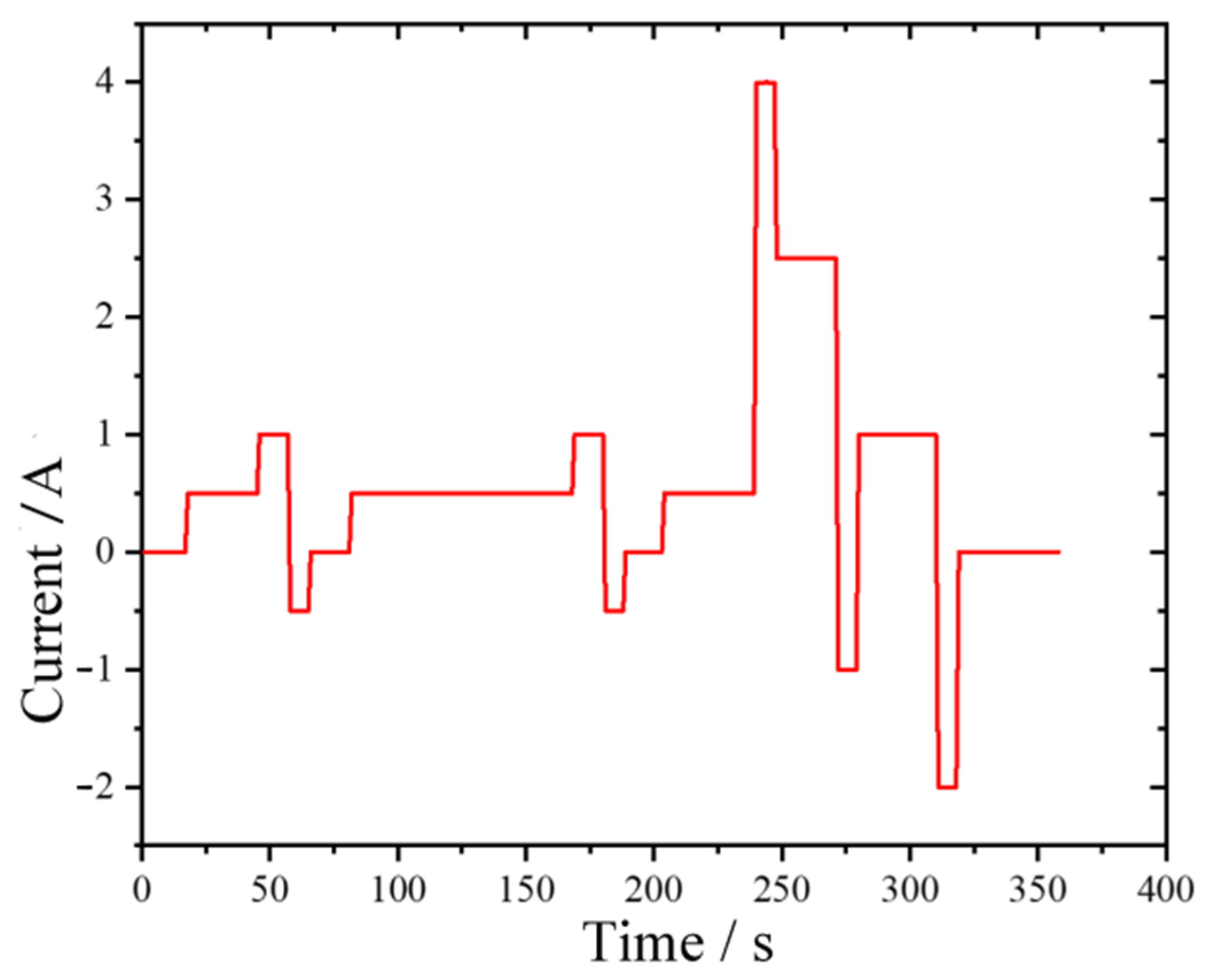
To better reflect the actual operating conditions of electric vehicles and to enhance the credibility of the model and parameter identification, a Dynamic Stress Test (DST) was employed to validate the battery model and parameters. The duration of a single DST cycle is 360 s. The current profile for a single DST cycle is shown in Figure 2.
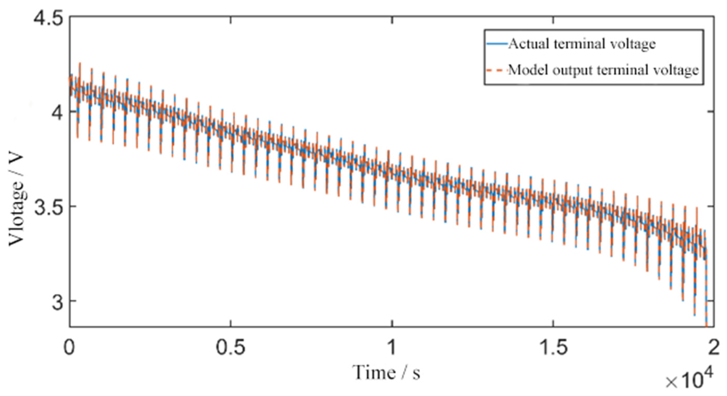
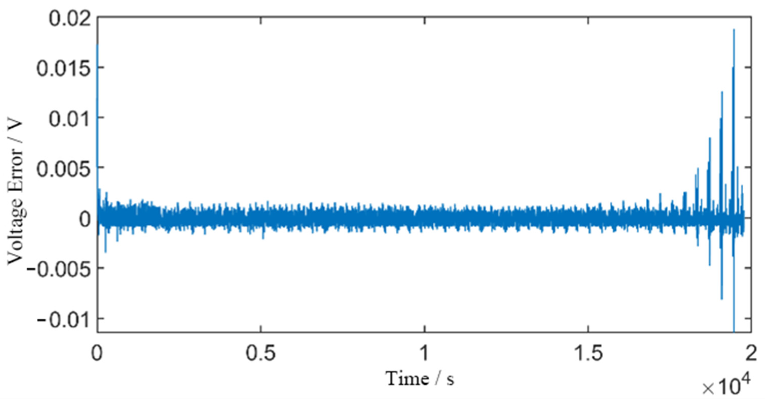
The FFRLS algorithm was implemented in MATLAB/Simulink (2018b) to perform parameter identification of the battery. The current and voltage values under the DST profile were used as inputs for online identification. By substituting the online identification results into the battery model, the comparison between the model-predicted terminal voltage and the experimental terminal voltage, as well as the terminal voltage error, can be obtained, as shown in Figure 3 and Figure 4. To further illustrate the effectiveness of the FFRLS-based parameter identification, Table 3 presents the identified second-order RC model parameters for different SOC intervals (extracted from the DST profile). The results demonstrate a clear dependency of internal resistances and capacitances on SOC, reflecting the nonlinear electrochemical behavior of the battery.
As shown in Figure 3 and Figure 4, apart from relatively larger voltage errors observed at the beginning and the end of the discharge process, where the maximum absolute error is approximately 20 mV, the voltage error at other times remains essentially within ±5 mV. These results demonstrate that the online identification method based on FFRLS exhibits high accuracy and can effectively capture the real-time state of the battery. Furthermore, they validate the high accuracy of the second-order RC equivalent circuit model. In the subsequent SOC estimation, the parameter identification results obtained from the FFRLS algorithm are employed to improve estimation performance.

4. CA-SVDUKF Algorithm

4.1. Standard UKF Algorithm Procedure

In the extended Kalman filter (EKF), only the first-order terms are retained during the Taylor series expansion, while higher-order terms are neglected. As a result, the EKF may introduce significant errors when applied to highly nonlinear state-space models. To address this issue, the unscented Kalman filter (UKF) integrates the standard Kalman filtering framework with the unscented transformation. Assuming that the nonlinear system is discretized, the state-space equations can be expressed as follows:
State equation:
x k + 1 = f x k , u k + w k
Observation equations:
y k = h x k , u k + v k
Let x k denote the system state variable at time k , y k the system observation output at time k , and u k the system input at time k . The function f x k , u k represents the state transition model of the system, while h x k , u k denotes the measurement model. The terms w k and v k correspond to the process noise and measurement noise of the system, respectively. Both are assumed to follow zero-mean Gaussian distributions and are mutually uncorrelated, with w k ~ N 0 , Q k and v k ~ N 0 , R k . Here, Q k is the covariance matrix of the process noise, Q k = E w k w k T , and R k is the covariance matrix of the measurement noise, R k = E v k v k T .
The unscented Kalman filter (UKF) algorithm proceeds as follows:
(1) Initialize the system state variables and the error covariance matrix.
x ^ 0 = E x 0 ,   P 0 = E x 0 x ^ 0 x 0 x ^ 0 T
(2) Apply the unscented transformation (UT) to obtain 2n + 1 sigma points along with their corresponding weights.
χ i , k 1 = x ^ k 1 , i = 0 x ^ k 1 + ( n + λ ) P k 1 i , i = 1 , 2 , , n x ^ k 1 ( n + λ ) P k 1 i , i = n + 1 , n + 2 , , 2 n
The weights of the sigma points are given by:
ω 0 m = λ / ( n + λ ) ω 0 c = ω 0 m + 1 α 2 + β ω i c = ω i m = 1 / [ 2 ( n + λ ) ] , i = 1 2 n
(3) Substitute Equation (11) into the state transition equation to compute the one-step predicted values of the sigma point set.
x i , k | k 1 = f χ i , k 1 , u k 1
(4) Perform a weighted summation of the one-step predicted sigma points obtained in Equation (13) with their corresponding weights to derive the prior estimate of the system state variables, and compute the estimate of the error covariance matrix.
x ^ k | k 1 = i = 0 2 n ω i m x i , k | k 1
P k | k 1 = i = 0 2 n ω i c x i , k | k 1 x ^ k | k 1 x i , k | k 1 x ^ k | k 1 + Q k 1
(5) Based on the prior estimate of the system state variables, apply the UT again to construct a new set of sigma points.
X i , k | k 1 = x ^ k | k 1 , i = 0 x ^ k | k 1 + ( n + λ ) P k | k 1 i , i = 1 , 2 , , n x ^ k | k 1 ( n + λ ) P k | k 1 i , i = n + 1 , n + 2 , , 2 n
(6) Substitute Equation (16) into the measurement equation of the system to obtain the one-step predicted values of the system observations.
y i , k | k 1 = h X i , k | k 1 , u k 1
(7) Perform a weighted summation of the one-step predicted values obtained in Equation (17) with their corresponding weights to derive the estimate of the system observations, and calculate both the covariance matrix P y y and the cross-covariance matrix P x y .
y ^ k | k 1 = i = 0 2 n ω i m y i , k | k 1
P y y , k = i = 0 2 n ω i c y i , k | k 1 y ^ k | k 1 y i , k | k 1 y ^ k | k 1 T + R k 1
P x y , k = i = 0 2 n ω i c x i , k | k 1 x ^ k | k 1 y i , k | k 1 y ^ k | k 1 T
(8) Compute the Kalman gain.
K k = P x y , k / P y y , k
(9) Update the posterior estimate of the system state variables and the posterior error covariance matrix.
x ^ k = x ^ k | k 1 + K k y k y ^ k | k 1
P x , k = P k | k 1 K k P y y , k K k T
Steps (1) ~ (9) together constitute the complete procedure of the Unscented Kalman Filter (UKF) algorithm.

4.2. Improvements to the UKF Algorithm

4.2.1. SVD-UKF Algorithm

Although the unscented Kalman filter (UKF) achieves high computational accuracy, the Unscented Transformation (UT) requires a Cholesky decomposition of the error covariance matrix. However, under practical operating conditions, disturbances caused by unknown noise or abrupt changes in the direction and magnitude of current may render the error covariance matrix non-positive definite. This situation leads to the termination of algorithm iterations. In the context of electric vehicles, premature termination of SOC estimation may result in severe consequences. To address the issue of iteration failure caused by a non-positive definite covariance matrix and to enhance the stability of the algorithm, singular value decomposition (SVD) is introduced as a substitute for the Cholesky decomposition in the iterative process of the traditional UKF algorithm [20]. The basic concept of SVD is introduced as follows:
Assume a matrix P R m × n ( m n ) , whose singular value decomposition (SVD) is expressed as follows:
P = U S V T = U 0 0 0 V T
where U R m × m , V R n × n and S R m × n .
The implementation of the SVD-UKF algorithm simply requires replacing the Cholesky decomposition in the standard UKF algorithm with SVD. Specifically, Equation (11) is replaced by Equations (25) and (26).
P k 1 = U k 1 S k 1 V k 1
χ i , k 1 = x ^ k 1 , i = 0 x ^ k 1 + U k 1 ( n + λ ) S k 1 i , i = 1 , 2 , , n x ^ k 1 U k 1 ( n + λ ) S k 1 i , i = n + 1 , n + 2 , , 2 n
Equation (16) is replaced by Equations (27) and (28).
P k | k 1 = U k | k 1 S k | k 1 V k | k 1
X i , k | k 1 = x ^ k | k 1 , i = 0 x ^ k | k 1 + U k | k 1 ( n + λ ) S k | k 1 i , i = 1 , 2 , , n x ^ k | k 1 U k | k 1 ( n + λ ) S k | k 1 i , i = n + 1 , n + 2 , , 2 n
The remaining steps of the SVD-UKF algorithm are essentially identical to those of the standard UKF algorithm and are therefore omitted here.

4.2.2. Noise Covariance Matching Method

The standard UKF algorithm for SOC estimation requires accurate prior statistical information regarding the characteristics of both process and measurement noise. However, since batteries are nonlinear systems, their process and measurement noise are time-varying. Consequently, adaptive noise estimation is crucial for enhancing the performance of UKF-based estimation and filtering. In this study, the innovation covariance matching method is introduced to adaptively update the covariance matrices Q k and R k [21].
The innovation e k of the measurement variable is defined as the difference between the actual measurement and its predicted value, i.e.,
e k = y k y ^ k | k 1
The adaptive update procedure of the noise covariance matrices is given as follows:
C k = 1 L i = k L + 1 k e i e i T
Q k = K k C k K k T R k = C k + i = 0 2 n ω i c y i , k | k 1 y ^ k | k 1 y i , k | k 1 y ^ k | k 1 T
where C k denotes the innovation covariance function, and L represents the window length, which is empirically set to 3 in this work.
Based on Equations (29)~(31), the adaptive update of the noise covariance matrices can be accomplished. Compared with the traditional UKF algorithm, this method utilizes the innovation sequence derived from the actual measurements and predicted observations to perform real-time correction and updating of the noise covariance, thereby reducing the impact of unknown noise on the algorithm.

4.2.3. Adaptive Error Covariance Matrix Method

During the actual operation of electric vehicles, frequent emergency braking as well as acceleration and deceleration events often occur. These operating conditions lead to abrupt changes in battery current. Such current transients slow down the convergence speed and may prevent rapid and accurate estimation of the SOC. The posterior error covariance matrix P x , k reflects the confidence level of the system’s estimation results: the larger the elements in the P x , k matrix, the lower the confidence in the estimation. When a sudden change occurs in the system input, the elements of the P x , k matrix increase, thereby slowing convergence. To mitigate the adverse effects of current transients on SOC estimation and improve estimation accuracy, this paper proposes an adaptive error covariance matrix method with a scaling factor.
The adaptive scaling factor is defined as δ k = e k T P y y , k 1 e k , and the adaptive threshold is denoted as δ 0 . When δ k > δ 0 , the posterior error covariance matrix is updated according to
P x , k = δ k P k | k 1 K k P y y , k K k T
The critical aspect of this method lies in the selection of the adaptive threshold δ 0 . If δ 0 is set too large, the filtering accuracy decreases; if it is set too small, the P x , k matrix must be updated at every iteration, which increases computational complexity. To address this, the mean and variance of δ are calculated within a sliding window, as shown in Equations (33) and (34).
μ = 1 L i = k L + 1 k δ i
σ = 1 L i = k L + 1 k δ i μ 2
The adaptive threshold δ 0 = n σ is defined with N = 5 in this work.
Compared with the standard UKF algorithm, the proposed covariance-based adaptive method performs corrections of the process and measurement noise covariance matrices Q k and R k during each iteration, thereby enhancing the robustness of the algorithm against unknown noise. In addition, an adaptive error covariance matrix method with a scaling factor is introduced to address the problem of reduced filtering responsiveness caused by sudden current transients. By setting an appropriate adaptive threshold, unnecessary updates of the posterior error covariance matrix P x , k at each iteration are avoided, which reduces computational complexity to a certain extent. By combining the covariance-based adaptive method proposed in this section with the previously introduced SVD-UKF algorithm, the final CA-SVDUKF algorithm for SOC estimation is established.

4.3. Design of the CA-SVDUKF Algorithm

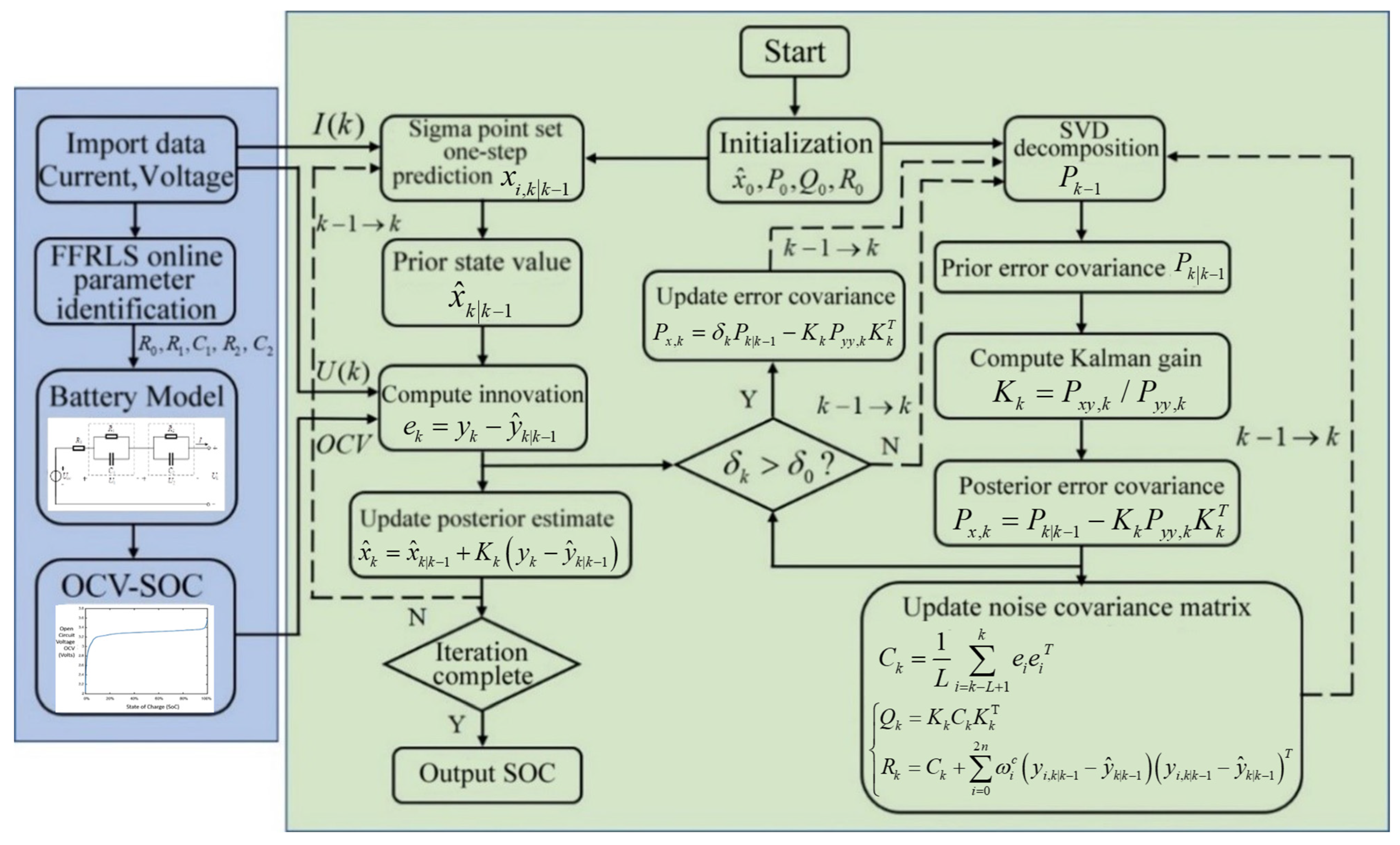
The system model parameters identified using the FFRLS algorithm in Section 2.2 are employed as the input parameters of the CA-SVDUKF algorithm. The flowchart of the CA-SVDUKF algorithm is shown in Figure 5, where the blue section represents the FFRLS algorithm, and the green section corresponds to the CA-SVDUKF algorithm.

5. Verification of SOC Simulation Results

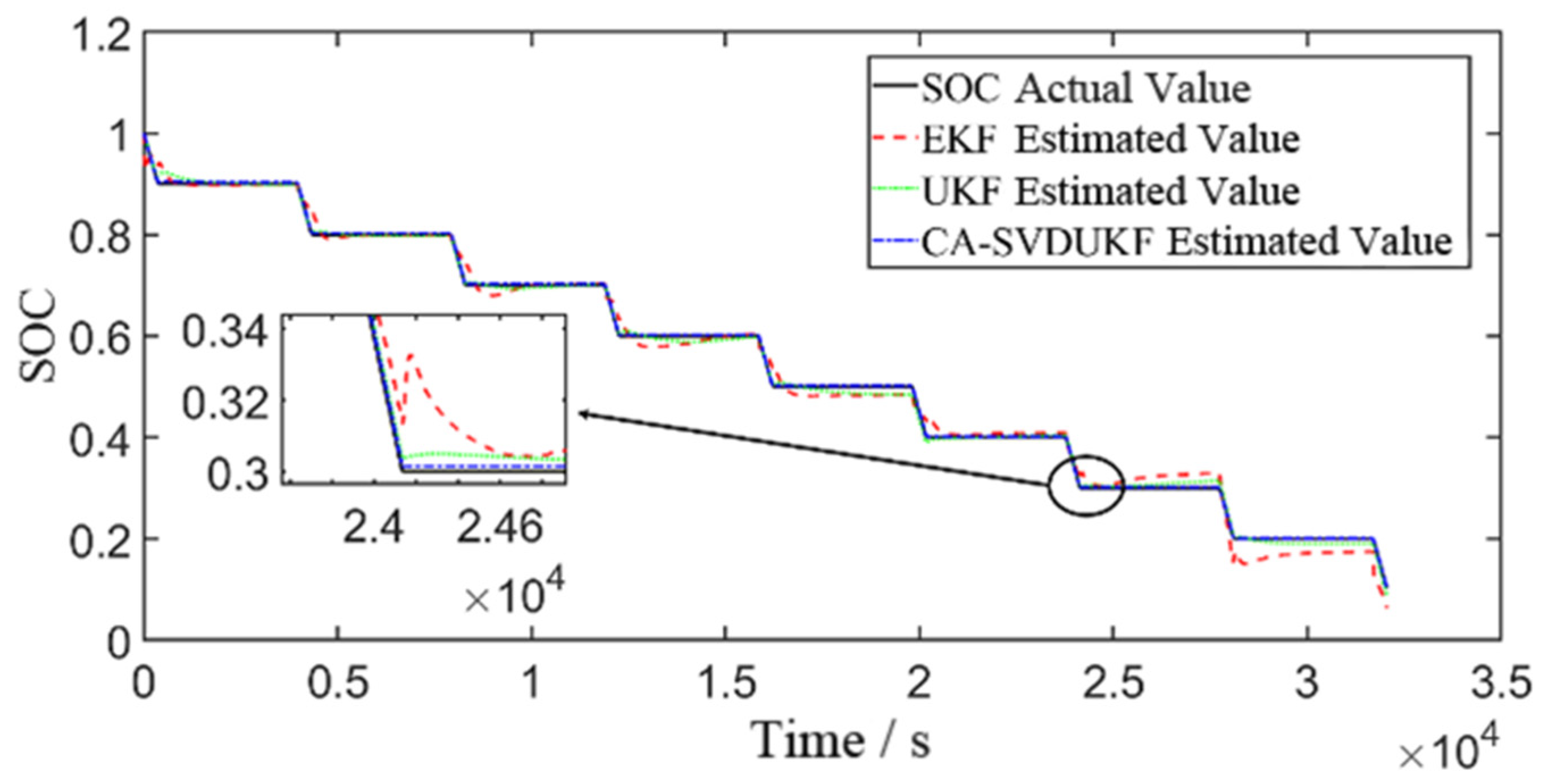
To validate the estimation performance of the proposed CA-SVDUKF algorithm, this section presents simulation studies comparing the EKF, UKF, and CA-SVDUKF algorithms under different operating conditions. Based on the model parameters identified by the FFRLS algorithm in Section 2.2, experimental current and voltage data under various conditions are applied to the three algorithms. Three operating conditions are considered: the standard pulse condition, the DST condition, and the US06 condition.
To ensure the reproducibility and fairness of the comparative estimation, the initialization settings for EKF, UKF, and CA-SVDUKF are listed in Table 4. These configurations were kept consistent across all three algorithms unless otherwise stated.

5.1. Standard Pulse Discharge Condition

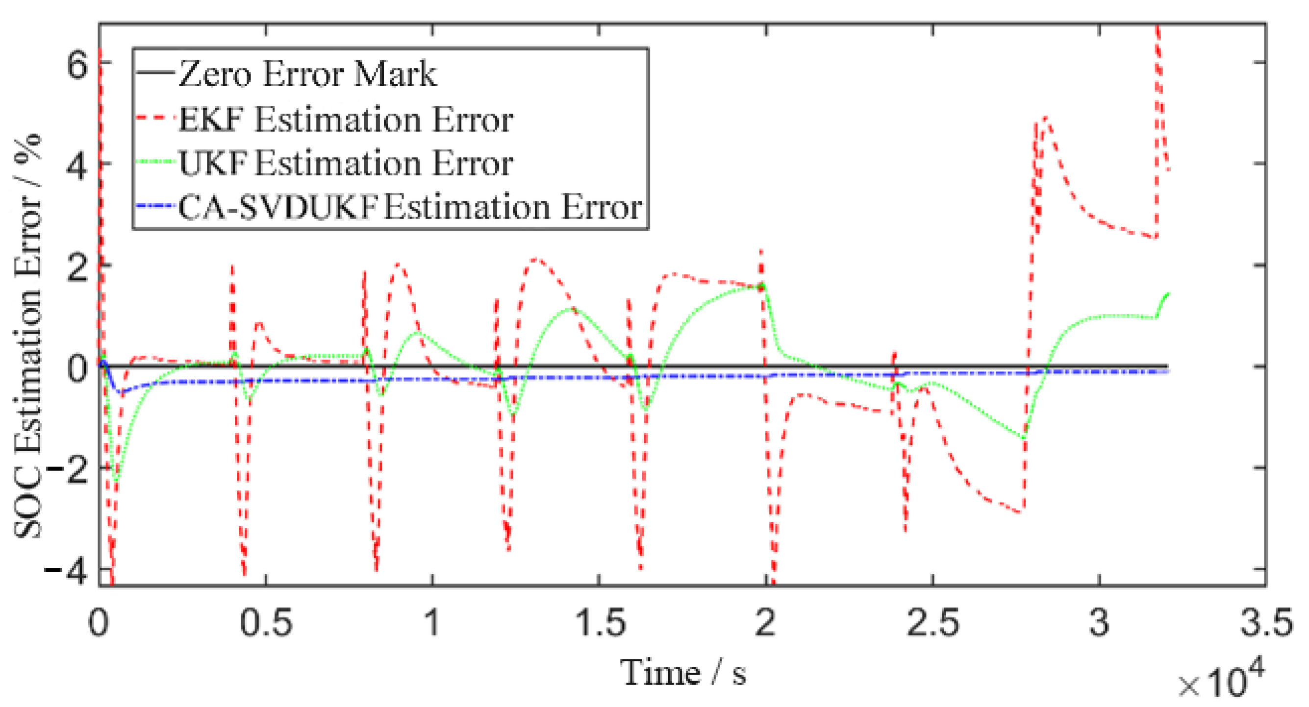
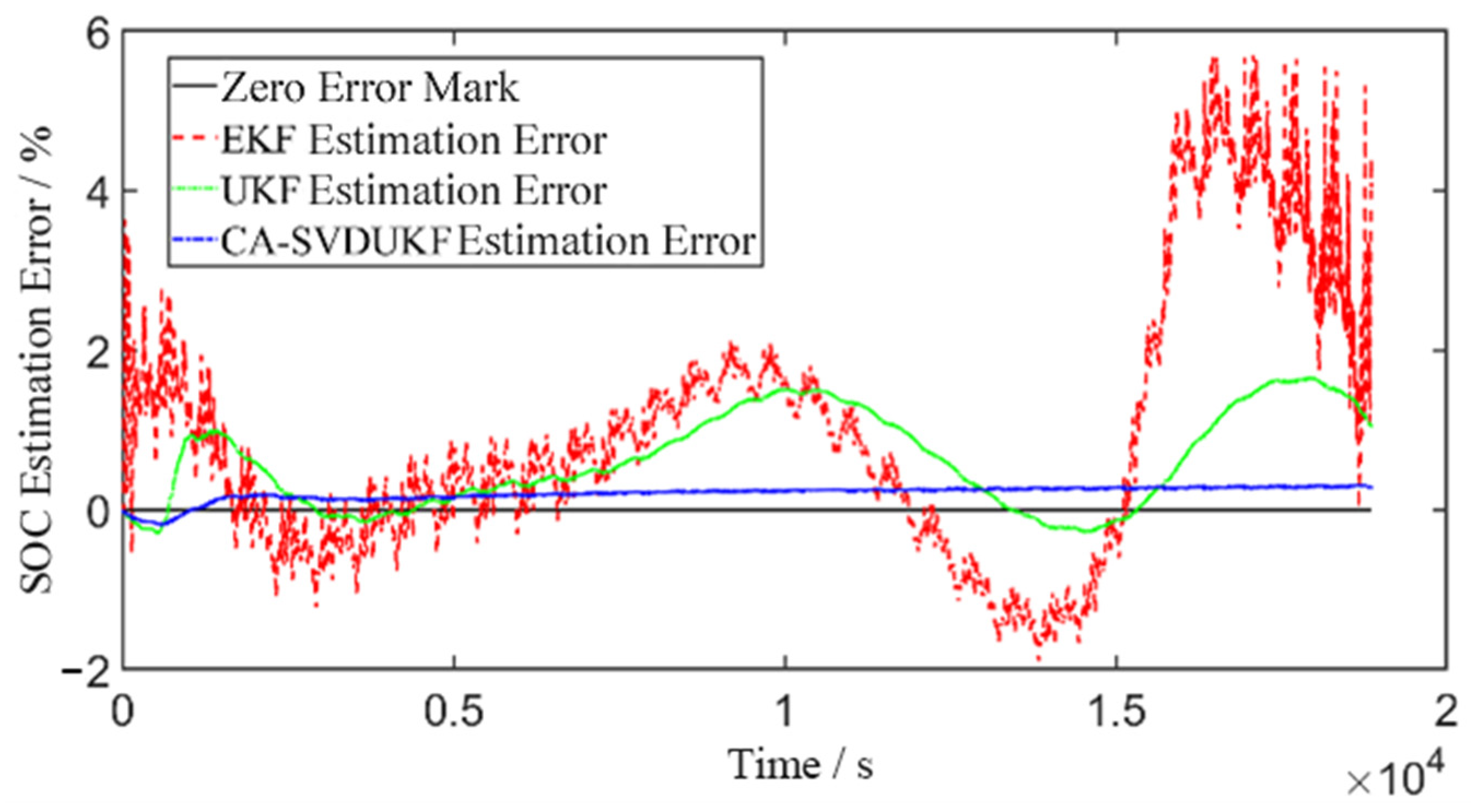
The SOC estimation results and corresponding errors of the three algorithms under the standard pulse discharge condition are shown in Figure 6 and Figure 7. Analysis of these figures indicates that, at the beginning of discharge, all three algorithms exhibit relatively large errors, with the EKF algorithm showing an absolute error of up to 6%. As the discharge progresses, the CA-SVDUKF algorithm rapidly converges through adaptive adjustment, maintaining the error within 0.3% throughout. In contrast, the EKF and UKF algorithms exhibit significant oscillations; in particular, under sudden discharge conditions, the absolute error of EKF rises sharply to around 4%, while that of UKF increases to approximately 2%. Toward the end of discharge, both EKF and UKF experience considerable errors, whereas CA-SVDUKF maintains high estimation accuracy. Over the entire discharge cycle, the maximum absolute error of CA-SVDUKF is only 0.512%, substantially lower than the 6.767% and 2.277% observed for EKF and UKF, respectively. Moreover, the root mean square error (RMSE) of CA-SVDUKF is just 0.230%, also outperforming EKF and UKF. These results demonstrate that, under the standard pulse condition, the proposed CA-SVDUKF algorithm achieves higher accuracy and stronger robustness against disturbances compared with EKF and UKF.

5.2. DST Condition

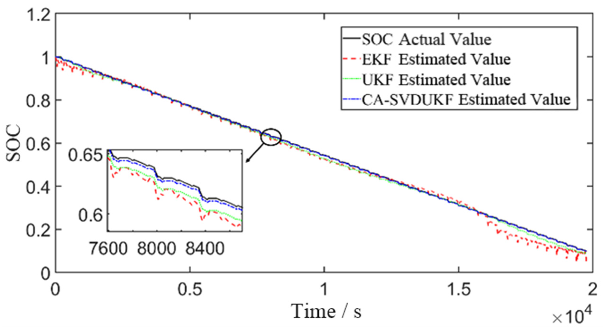
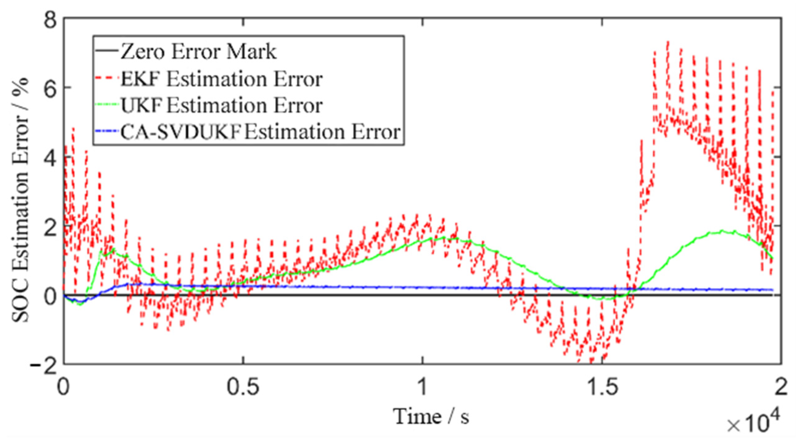
In the practical operation of electric vehicles, the battery typically experiences variable current profiles. To better replicate real operating conditions and evaluate the estimation performance of the algorithm under sudden current variations, the DST condition is adopted for validation. The current profile of the DST condition has been provided in Section 2.2. The SOC estimation results and corresponding errors of the three algorithms under the DST condition are shown in Figure 8 and Figure 9.
From the analysis of Figure 8 and Figure 9, it can be observed that the EKF and UKF algorithms exhibit relatively large absolute errors during both the initial and final stages of discharge. In particular, the EKF algorithm shows an absolute SOC estimation error as high as 7.342% at the end of discharge. In contrast, the estimation error of the CA-SVDUKF algorithm remains stable, generally within 0.35%. During the mid-discharge stage, the EKF and UKF algorithms display significant oscillations, especially when sudden discharge occurs, where the EKF estimation results exhibit large fluctuations. The error of the CA-SVDUKF algorithm tends to converge to the error baseline, while the EKF and UKF algorithms demonstrate a divergence trend in the later discharge stage. Throughout the entire DST discharge cycle, the RMSE of the CA-SVDUKF algorithm is only 0.214%, which is substantially lower than the 2.113% and 1.000% observed for EKF and UKF, respectively. These results indicate that, under the DST condition, the CA-SVDUKF algorithm provides considerable improvements in both accuracy and stability compared with EKF and UKF. Furthermore, due to its adaptive correction and updating of the error covariance matrix during iterations, the CA-SVDUKF algorithm demonstrates strong tracking capability under sudden current variations, resulting in smaller estimation fluctuations.

5.3. US06 Condition

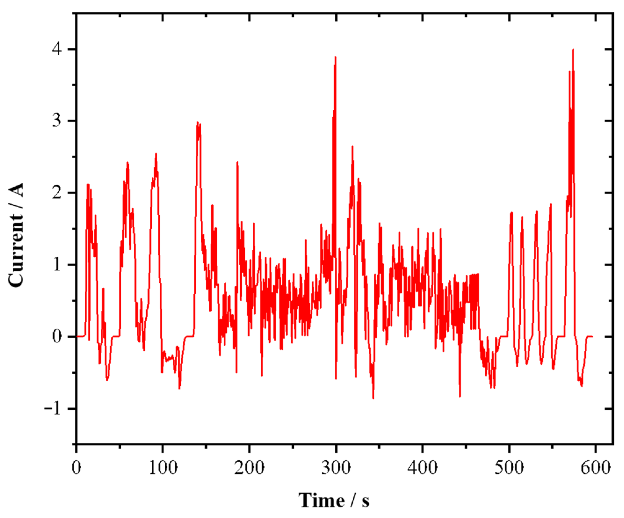
The US06 condition, proposed by the U.S. Environmental Protection Agency (EPA), is designed to evaluate the performance of electric vehicles under demanding driving scenarios such as high speeds, aggressive acceleration, and intensive driving behavior. Compared with the DST condition, the US06 condition features more frequent current transients and a higher average current. Consequently, it imposes stricter requirements on the accuracy and fast-tracking capability of SOC estimation algorithms. The duration of a single US06 cycle is 600 s. The current profile of a single US06 cycle is shown in Figure 10.
The SOC estimation results and estimation errors of the three algorithms under the US06 driving condition are presented in Figure 11 and Figure 12, respectively.
From the analysis of Figure 11 and Figure 12, it can be observed that under the US06 condition, where current transients occur frequently, the estimation errors of the EKF and UKF algorithms exhibit significant fluctuations, whereas the error curve of the CA-SVDUKF algorithm remains comparatively stable. Compared with the traditional UKF algorithm, the maximum absolute error of the CA-SVDUKF algorithm is reduced by 1.342%. Over the entire discharge cycle under the US06 condition, the root mean square error (RMSE) of the CA-SVDUKF algorithm is only 0.225%, which is considerably smaller than those of the EKF and UKF algorithms (1.853% and 0.853%, respectively).

6. Conclusions

To address the limitations of conventional EKF and UKF algorithms, this study establishes a second-order RC equivalent circuit model of the battery. The model parameters are identified using an online identification method based on the FFRLS algorithm. Building upon the identified model and parameters, the CA-SVDUKF algorithm is employed for SOC estimation.
The proposed CA-SVDUKF algorithm replaces the Cholesky decomposition in the traditional UKF with singular value decomposition (SVD), thereby preventing iteration failures caused by nonpositive definite error covariance matrices. To overcome the lack of accurate prior statistical information on noise, a covariance-matching adaptive method is introduced, which enhances the robustness of the algorithm against unknown noise. Furthermore, an adaptive error covariance matrix method with a scaling factor is proposed to address the slowdown in filter convergence caused by abrupt current transients.
Simulation results under three different operating conditions demonstrate that the proposed SOC estimation method achieves higher accuracy and stability compared with EKF and UKF algorithms. Specifically, the maximum absolute error remains below 0.6% and the RMSE below 0.3% across all conditions, thereby validating the effectiveness and superiority of the proposed algorithm.

Author Contributions

Conceptualization, J.C. and X.H.; methodology, J.C.; software, X.H.; validation, J.C., X.H. and K.Y.; formal analysis, J.C.; investigation, K.Y.; resources, J.C. and X.H.; data curation, J.C.; writing—original draft preparation, J.C.; writing—review and editing, X.H. and K.Y.; visualization, X.H.; project administration, J.C. All authors have read and agreed to the published version of the manuscript.

Funding

This research received no external funding.

Data Availability Statement

The original contributions presented in the study are included in the article, further inquiries can be directed to the corresponding author.

Conflicts of Interest

The authors declare no conflicts of interest.

References

  1. Shen, M.; Gao, Q. A review on battery management system from the modeling efforts to its multiapplication and integration. Int. J. Energy Res. 2019, 43, 5042–5075. [Google Scholar] [CrossRef]
  2. Yu, Y.; Qian, X.; Yang, G. Accurate estimation of charge state of lithium battery based on fuzzy control. Electron. Meas. Technol. 2018, 41, 7–11. [Google Scholar] [CrossRef]
  3. Wu, X.; Li, X.; Du, J. State of Charge Estimation of Lithium-Ion Batteries Over Wide Temperature Range Using Unscented Kalman Filter. IEEE Access 2018, 6, 41993–42003. [Google Scholar] [CrossRef]
  4. Ali, M.U.; Zafar, A.; Nengroo, S.H.; Hussain, S.; Alvi, M.J.; Kim, H.-J. Towards a Smarter Battery Management System for Electric Vehicle Applications: A Critical Review of Lithium-Ion Battery State of Charge Estimation. Energies 2019, 12, 446. [Google Scholar] [CrossRef]
  5. Wang, Y.; Tian, J.; Sun, Z.; Wang, L.; Xu, R.; Li, M.; Chen, Z. A comprehensive review of battery modeling and state estimation approaches for advanced battery management systems. Renew. Sustain. Energy Rev. 2020, 131, 110015. [Google Scholar] [CrossRef]
  6. How, D.N.; Hannan, M.A.; Lipu, M.H.; Ker, P.J. State of Charge Estimation for Lithium-Ion Batteries Using Model-Based and Data-Driven Methods: A Review. IEEE Access 2019, 7, 136116–136136. [Google Scholar] [CrossRef]
  7. Wang, W.; He, F.; Jiang, X.; Zheng, Y.L. Research on state of charge estimation of lithium battery based on double extended Kalman filter. Electron. Meas. Technol. 2020, 43, 49–52. [Google Scholar] [CrossRef]
  8. He, Z.; Li, Y.; Sun, Y.; Zhao, S.; Lin, C.; Pan, C.; Wang, L. State-of-charge estimation of lithium ion batteries based on adaptive iterative extended Kalman filter. J. Energy Storage 2021, 39, 102593. [Google Scholar] [CrossRef]
  9. Gao, J.; Ai, T.; Xu, X.; Wang, F.F. Accurate SOC Estimation of the Lithium Iron Phosphate Battery Based on UKF. Electron. Meas. Technol. 2018, 41, 12–16. [Google Scholar] [CrossRef]
  10. An, Z.; Tian, M.; Zhao, L.; Chen, X.; Li, Y.; Si, X. SOC estimation of lithium battery based on adaptive untracked Kalman filter. Energy Storage Sci. Technol. 2019, 8, 856–861. [Google Scholar] [CrossRef]
  11. Zou, L.; Liu, J.; Ma, G.; Lang, J. Estimation of state of charge of lithium battery based on dual unscented Kalman filter. Chin. J. Power Sources 2021, 45, 450–454. [Google Scholar] [CrossRef]
  12. Deng, M.; Min, Q.; Yang, G.; Yu, M. Kalman Filter Estimation of Lithium Battery SOC Based on Model Capacity Updating. Energy Eng. 2022, 119, 739–754. [Google Scholar] [CrossRef]
  13. Dhanagare, T.; Singh, S.; Pandey, V. An Lstm-Driven Simulation Approach for Soc & Soh Estimation of a Lithium-Ion Cell. In Proceedings of the 2023 International Design Engineering Technical Conferences and Computers and Information in Engineering Conference, Boston, MA, USA, 20–23 August 2023; Volume 5. [Google Scholar]
  14. Xing, L.; Ren, H.; Luo, W.; Zhang, Z.; Song, Y. Online estimation of lithium battery SOC based on fractional order FOUKF-FOMIUKF algorithm with multiple time scales. Energy Sci. Eng. 2024, 12, 508–523. [Google Scholar] [CrossRef]
  15. Wang, X.; Gao, Y.; Lu, D.; Li, Y.; Du, K.; Liu, W. Lithium Battery SoC Estimation Based on Improved Iterated Extended Kalman Filter. Appl. Sci. 2024, 14, 5868. [Google Scholar] [CrossRef]
  16. Li, H.; Chen, F.; Xu, T.; Luo, S.; Mao, Y. Estimation of the state of charge of lithium batteries based on EKF-AEKF. Appl. Technol. 2024, 51, 102–108. [Google Scholar]
  17. Son, D.; Park, S.; Oh, J.; Lee, T.; Kim, S.W. Physics-informed dual-stage network for lithium-ion battery state-of-charge estimation under various aging and temperature condition. Appl. Energy 2025, 401, 126770. [Google Scholar] [CrossRef]
  18. Wu, L.; Wei, X.; Lin, C.; Huang, Z.; Fan, Y.; Liu, C.; Fang, S. Battery SOC estimation with physics-constrained BiLSTM under different external pressures and temperatures. J. Energy Storage 2025, 117, 116205. [Google Scholar] [CrossRef]
  19. He, H.; Xiong, R.; Guo, H.; Li, S. Comparison study on the battery models used for the energy management of batteries in electric vehicles. Energy Convers. Manag. 2012, 64, 113–121. [Google Scholar] [CrossRef]
  20. You, D.; Liu, P.; Shang, W.; Zhang, Y.; Kang, Y.; Xiong, J. An Improved Unscented Kalman Filter Algorithm for Radar Azimuth Mutation. Int. J. Aerosp. Eng. 2020, 2020, 8863286. [Google Scholar] [CrossRef]
  21. Xie, Y.; He, Z.; Chen, D.; Zhou, H. SOC Estimation of Power Battery Based on AUKF. J. Beijing Jiaotong Univ. 2018, 42, 129–137. [Google Scholar] [CrossRef]
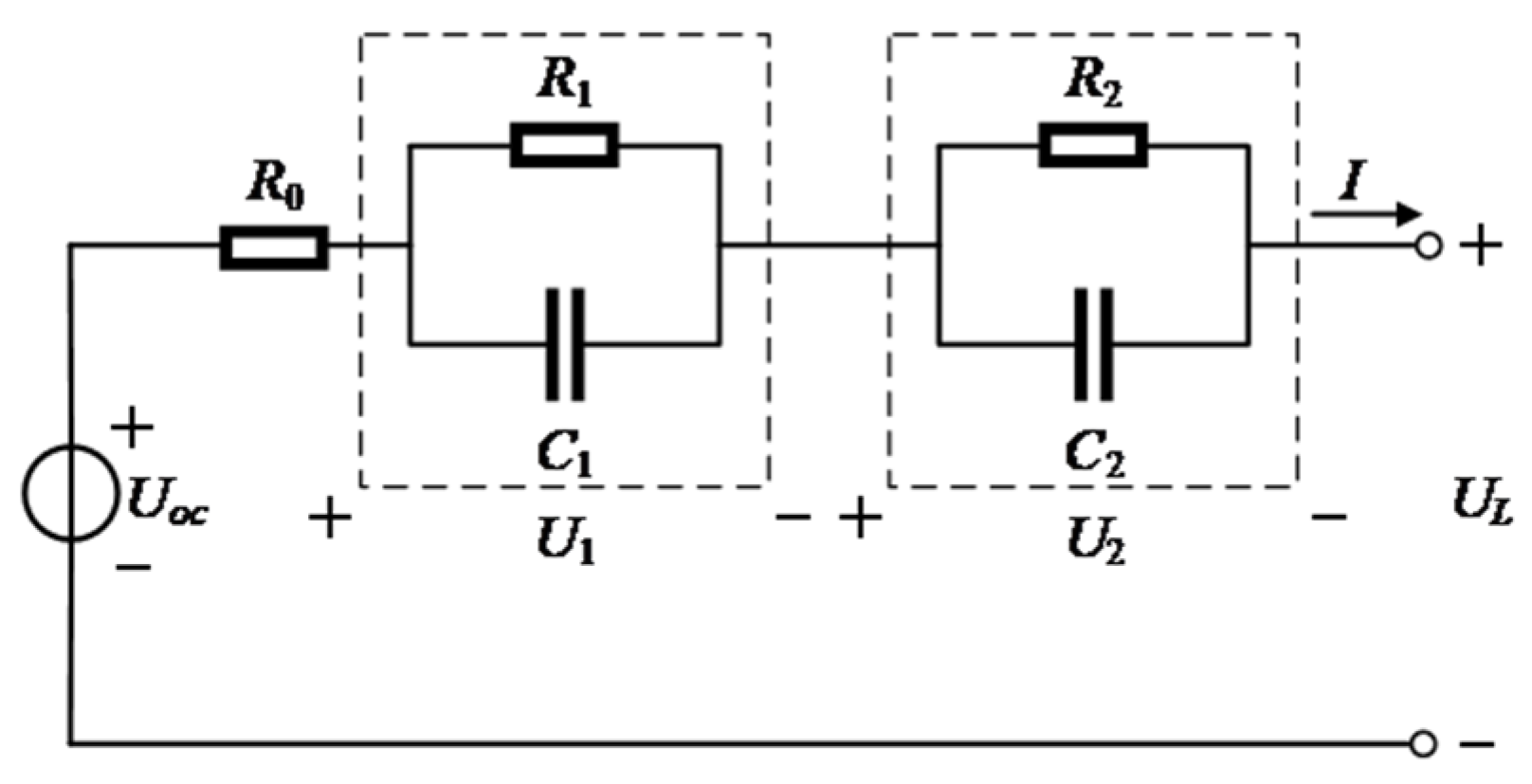
Figure 1. Second-order RC equivalent circuit model.
Batteries 11 00435 g001
Figure 2. Current profile of a single DST cycle.
Batteries 11 00435 g002
Figure 3. Comparison of terminal voltage under DST profile with online identification.
Batteries 11 00435 g003
Figure 4. Terminal voltage error under DST profile with online identification.
Batteries 11 00435 g004
Figure 5. Flowchart of the CA-SVDUKF algorithm.
Batteries 11 00435 g005
Figure 6. SOC estimation results of the battery under the constant pulse condition.
Batteries 11 00435 g006
Figure 7. SOC estimation errors of the battery under the constant pulse condition.
Batteries 11 00435 g007
Figure 8. SOC estimation results of the battery under the DST condition.
Batteries 11 00435 g008
Figure 9. SOC estimation errors of the battery under the DST condition.
Batteries 11 00435 g009
Figure 10. Single-cycle current profile under the US06 condition.
Batteries 11 00435 g010
Figure 11. SOC estimation results of the battery under the US06 condition.
Batteries 11 00435 g011
Figure 12. SOC estimation errors of the battery under the US06 condition.
Batteries 11 00435 g012
Table 1. Parameters of battery pulse test equipment.
Parameter of ApparatusSpecification
ModelMACCOR M4300
Number of Independent Test Channels8
Voltage Range0–5 V
Current Range60 uA–5 A
Minimum Step Time5 ms
Minimum Pulse Time100 us
Current Resolution/Accuracy16 Bit/±0.01% FS
Voltage Resolution/Accuracy0.076 mV/±0.02% FS
Table 2. Battery parameter table for test battery NCR-18650B.
Battery ParametersSpecification
Rated Capacity3.4 Ah
Maximum/Minimum Voltage4.2 V/2.5 V
Nominal Voltage3.6 V
Cathode/AcceptorNickel–cobalt–aluminum oxide lithium/graphite
Weight48.5 g
Temperature Range−20–60 °C
Table 3. Identified battery parameters at different SOC intervals.
SOC Interval (%)R0 (Ω)R1 (Ω)C1 (F)R2 (Ω)C2 (F)
90–1000.01320.008521500.01791480
80–900.01370.008921050.01851492
70–800.01430.009320700.01921505
60–700.01490.009820300.02011523
50–600.01560.010319920.02101538
40–500.01640.010919500.02201550
30–400.01730.011519080.02301567
20–300.01810.012218670.02431580
10–200.01900.012918200.02551602
Table 4. Initialization settings for EKF, UKF, and CA-SVDUKF algorithms.
ParameterEKF/UKF ValueNotes
Initial SOC estimate100%Same for all algorithms
Initial polarization voltages0 VFor both RC branches
Initial state error covariance (P_0)diag ([1 × 10⁻⁴, 1 × 10⁻⁴, 1 × 10⁻²])Corresponds to [V1, V2, SOC]
Process noise covariance (Q)diag ([1 × 10⁻⁶, 1 × 10⁻⁶, 1 × 10⁻⁶])Tuned for stability and responsiveness
Measurement noise covariance (R)1 × 10⁻³Based on experimental noise characterization
Sampling interval1 sFixed across all experiments
OCV–SOC lookupPulse-derived and curve-fittedSame lookup used across all filters
Disclaimer/Publisher’s Note: The statements, opinions and data contained in all publications are solely those of the individual author(s) and contributor(s) and not of MDPI and/or the editor(s). MDPI and/or the editor(s) disclaim responsibility for any injury to people or property resulting from any ideas, methods, instructions or products referred to in the content.