Review

Energetic Neutral Atom Imaging of the Earth’s Ring Current and Some Results from the Chinese Double Star Program

1
National Space Science Center, Chinese Academy of Sciences, Beijing 100190, China
2
Key Laboratory of Solar Activity and Space Weather, Beijing 100190, China
3
School of Science, Harbin Institute of Technology, Shenzhen 518055, China
4
Beijing Key Laboratory of Space Environment Exploration, Beijing 100190, China
*
Author to whom correspondence should be addressed.
Magnetochemistry 2023, 9(1), 29; https://doi.org/10.3390/magnetochemistry9010029
Submission received: 5 December 2022 / Revised: 30 December 2022 / Accepted: 4 January 2023 / Published: 12 January 2023
(This article belongs to the Special Issue Magnetodynamics of Space Plasmas)

Abstract

:
The ring current region in the Earth’s magnetosphere contains energetic charged particles, which are injected from the magnetotail, get trapped in the inner magnetosphere, and finally drift around the Earth. The current, essentially carried by ions, is caused by the differences between the drift of the positively charged ions and that of negatively charged electrons. The charge exchange that occurs between ring current ions and geocoronal atoms determines the distribution and evolution of the ring current and lays the basis for remote detection techniques. By measuring the energetic neutral atoms produced by the charge-exchange process, the ring current can be remotely detected via energetic neutral atom imaging. The Chinese Double Star Program operated the NeUtral Atom Detector Unit (NUADU) onboard one of its two satellites for more than four years. A variety of studies were conducted using multiple methods applied to observations, such as intuitive image inspection, forward modeling, and inversion. Energetic neutral atom imaging was established as a promising technique for future imaging projects.

1. Introduction

Space has an abundance of charged particles, namely plasmas consisting of electrons and ions. Compared with the lower atmosphere or ionosphere, the magnetosphere is so tenuous that the particles are virtually collisionless [1,2]. Regardless, collisionless particles are closely coupled with dynamic electromagnetic fields and experience complex motion [3,4].
Measuring the properties of plasmas, such as their spatial distribution, energy spectrum, and components, is crucial for understanding the dynamics of any region in space. In situ satellite measurements [5,6] are conventionally used for this purpose; however, such methods can only provide a single-point measurement in time, and it is difficult to acquire a full view of a large region or structure, particularly in the case of large temporal variation.
Similar to optical photography, it is possible to capture an “image” of a space region by counting energetic neutral atoms (ENAs) originating there. ENAs are produced via a charge-exchange reaction between energetic ions and low-energy neutral atoms [7]. Once produced, a neutral atom leaves the reaction location, keeping the energy and moving direction that its mother particle possesses exactly when the reaction occurs. Immune from the electromagnetic field influence, energetic neutral atoms take nearly straight paths (like photons). Counting neutral atoms’ incidence from different directions underlies remote imaging or photography.
Owing to its considerable advantages over conventional in situ measurements, great effort has been devoted to technological development and scientific research concerning ENA imaging, particularly for Earth’s ring current that is abundant with energetic ions. At the early stage, ENA signatures were captured by some energetic ion detectors that were not dedicated to measuring ENA, such as those flown on ISEE 1/2 [8], GEOTAIL [9], and POLAR [10] missions. Detection of ENAs was unambiguously established by IMP7/8 and ISEE 1 measurement, and their source was identified as the ring current [11]. This was a major milestone in validating the idea that magnetospheric processes can be effectively studied by remotely measuring ENAs. An instrument with a dedicated high-energy ENA detection channel was flown on the CRRES satellite [12], followed by deploying of the first dedicated ENA camera onboard the ASTRID satellite [13]. More productive ENA imaging measurements were performed by subsequent IMAGE [14] and TWINS [15] missions. The IMAGE mission adopted three specially designed ENA cameras in different energy ranges and for different objectives, namely the high energy instrument, HENA measuring 10–500 Kev energy to study Earth’s ring current, the medium ENA instrument, MENA measuring 1–30 Kev to study the plasma sheet, and the low ENA instrument, LENA measuring between 10 eV and 500 eV to study the ionospheric source of ions flowing from the polar cap. TWINS mission for the first time provided stereo ENA imaging of Earth’s magnetosphere using simultaneous imaging from two satellites [16]. In addition to detecting geospace, ENA imaging has also been applied to planetary or heliosphere studies; examples include the Cassini mission for Saturn [17] and the IBEX mission for sensing the interaction between the heliosphere’s boundary and interstellar medium [18]. The Jupiter Icy Moons Explorer (JUICE), currently under development, was also set to carry an ENA camera to explore Jupiter, Ganymede, and Europa [19]. Applying the ENA imaging technique to other planets has been considered by the scientific community [20,21]. It is out of the scope of this paper to make a detailed review of the evolution of ENA detecting techniques and a full series of relative missions, interested readers are referred to the comprehensive review article by Gruntman [22].
The Double Star Program (DSP) is a cooperative endeavor undertaken by China and the European Space Agency (ESA) [23,24]. It consists of two satellites, named ‘TC-1’ and ‘TC-2’, which were launched in 2003 and 2004, respectively. TC-1 undertook an eccentric equatorial orbit to cover the magnetotail regions, and TC-2 had an eccentric polar orbit, which is advantageous for a global view of the ring current from an elevated position over the polar regions. The DSP and the four-satellite European Cluster mission [25] were put into a combination that constituted a six-point observation constellation in the geospace.
The ENA imaging instrument onboard TC-2, the Energetic NeUtral Atom Detector Unit (NUADU) [26,27], was the primary payload of the satellite. This was the first Chinese magnetospheric mission to successfully photograph the Earth’s ring current. This current article aims to expand on some concepts about ring current and charge exchange that is fundamental for ENA imaging and reviews several studies based on NUADU observations.

2. The Earth’s Ring Current

Electrons and ions, or plasmas, move actively in space under the influence of electromagnetic fields [3]. An electric current arises once a motion difference occurs. Hence, there are always complicated currents flowing around Earth, including the ring current [2,3,28,29].
The geomagnetic field predominantly exhibits a dipolar pattern in the inner magnetosphere [30]. Charged particles immersed there mainly take three types of motion with regard to magnetic field lines: gyration, bouncing between mirror points, and transverse drift motion [3]. These motions can take place over time scales of milliseconds, seconds, and hours [3]. Owing to the swift response of particles to any electric field parallel to the magnetic field, macroscopic charge separation or current along the field lines is usually negligible. For drift motion, an electric current arises owing to different particle drifting directions, which are westward for ions and eastward for electrons [3,7]. In plasmas with a density gradient perpendicular to the magnetic field, the gyration of the charged particles also contributes to the electric current (i.e., the polarization current) [31]. The density of the total perpendicular ring current can be calculated with the following equation [31]:
j = [ × P B B 2 ] + B B 2 × P B B + B B 2 × P b b + B B 2 ρ d v d t
where B is the magnetic field, b is the unit vector of the magnetic field lines, ρ is the plasma mass density, P|| and P are the parallel and perpendicular plasma pressures with respect to the magnetic field, respectively, and v is the plasma bulk velocity. The terms within the equation represent, in order, the magnetized current, magnetic field gradient drift current, magnetic field curvature drift current, and polarization current.
The ring current is in a donut shape encircling the Earth and is mirror-symmetric about the equatorial plane. Its geocentric distance may range from 2 to 7 RE (Earth radius), depending on the geomagnetic condition, which is ultimately affected by solar activities and solar wind-magnetosphere interaction [32,33,34]. Ring-current particles are believed to be injected from the plasma sheet within the magnetotail during geomagnetic storms, although the detailed mechanism is yet to be determined [7,35]. Stationary pictures of the magnetosphere during storms (Figure 1) indicate that particles drift from the magnetotail toward the Earth approximately along equal-potential lines and drift around the Earth under control of the curved geomagnetic field. Upon crossing the injection boundary, the particles are essentially subject to magnetic drift (gradient drift and curvature drift) rather than the E×B drift they experienced in the magnetotail. This storm time convection, or injection, results in a stronger ring current at a position closer to Earth. For long-duration convection, particles may readily drift out and become lost at the magnetopause [7].
According to the Biot–Savart law, the ring current causes perturbation of the geomagnetic field at the surface of Earth, mainly in the horizontal (H) component [36,37]. Building up the ring current and the resultant drop in the ground geomagnetic field are the two most prominent features of geomagnetic storms [38,39]. To measure the overall intensity of ring currents and geomagnetic storms, Chapman and Bartels [40] developed a disturbance storm time (Dst) index. The Dst index represents the longitudinally averaged part of the external field measured at the geomagnetic dipole equator on the Earth’s surface [41]. The most commonly used definition of a geomagnetic storm is an event in which the minimum Dst index is below a critical value [39].
Characterized by the variation in the Dst index, the evolution of a geomagnetic storm is usually divided into the main phase and recovery phase, corresponding to the building-up and decay of the ring current [7,38,39]. In some cases, before the main phase, a short interval features an abrupt increase in Dst, known as the Sudden Storm Commencement (SSC) phase [39].
Notably, the ring current does not occupy an exclusive region in the geospace. To some extent, it overlaps with the radiation belt abundant in hazardous high-energy particles, the plasmasphere with low-energy cold particles [42], and the geocorona or outermost part of the Earth’s atmosphere consisting primarily of cold hydrogens [43]. This creates an environment for many complex interactions to take place, among which the interaction between ring current ions and geocoronal particles contributes greatly to the decay of the ring current and produces neutral atoms that can be utilized with precision for ENA imaging techniques [7,13,14,15,44].
In contrast to other particles that may appear in the same spatial region, the ring-current particles are correctly recognized by their contribution to the current density. Ions with energy from 10 KeV to 200 KeV are the main current carriers of Earth’s ring current [7,45]. In general, most ions are hydrogen ions (H+), however, oxygen (O+) may become dominant during strong geomagnetic storms [46,47]. Helium (He+) is a minority species in the ring current, and is not negligible in some circumstances. Different types of ions may have different origins, leading to characteristic decay times [7,44]. This complicates the evolution of the ring current.

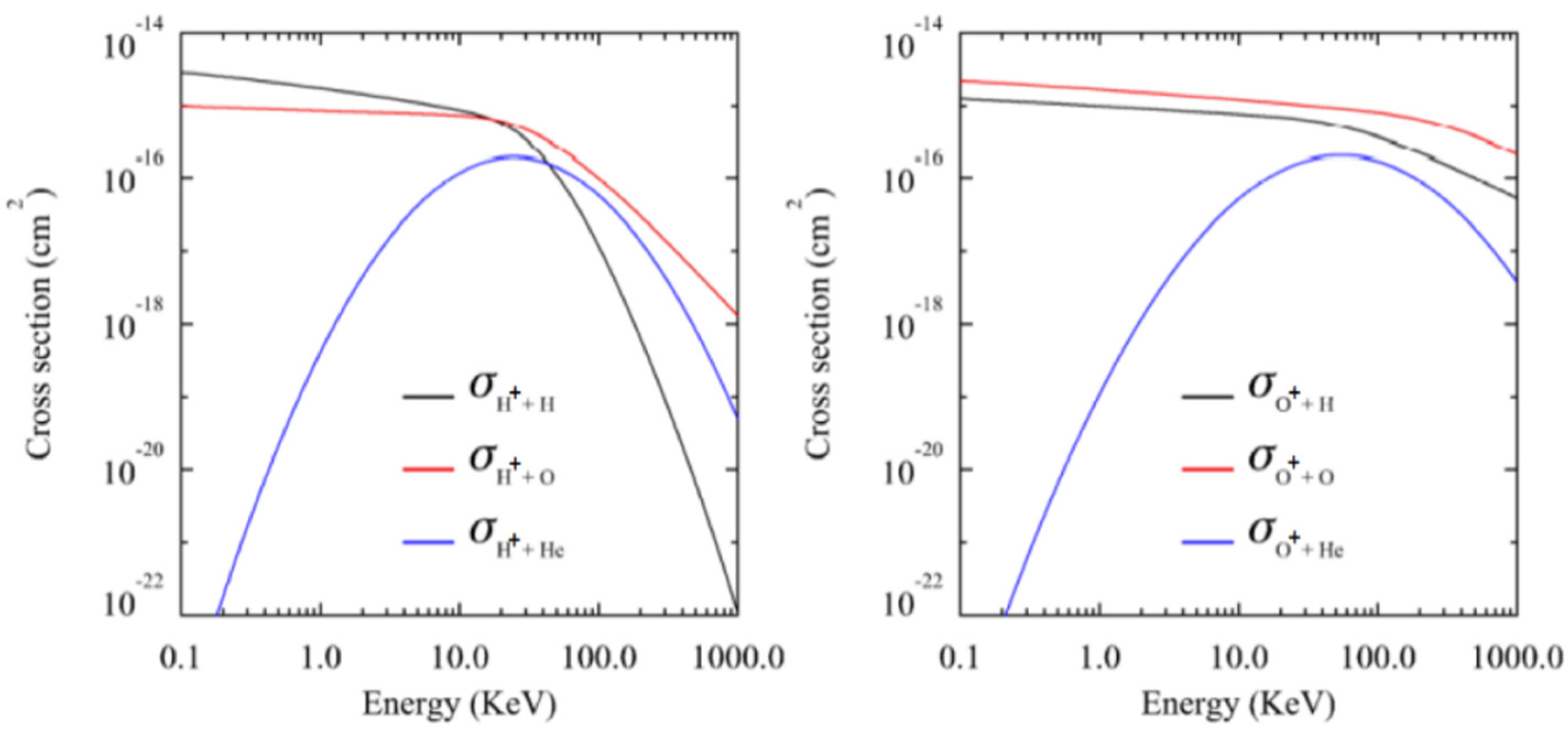
3. Charge-Exchange Reaction

The charge-exchange reaction is a collisional process between an ion and a neutral atom or molecule, wherein one or more electrons are transferred from the neutral atom to the ion. In space, owing to acceleration by electromagnetic fields, ions are naturally more energetic than neutrals [7]. Hence, the charge-exchange process usually ends with a fast ENA and low-energy ion. Radiation, most likely X-rays, may also be produced when the transferred excited electrons return to the ground energy state during the reaction [44,48]. This process imposes non-negligible effects on the physics of the planetary atmosphere, galaxy, or cosmos. It also provides two valuable methods, ENA and X-ray remote sensing, to survey space or the cosmos. Figure 2 shows an example of charge exchange reaction between energetic oxygen ions and geocoronal hydrogen neutral atoms.
Because regions of the ring current and the geocorona overlap, there is a possibility that a ring current energetic ion may collide with a geocoronal hydrogen or oxygen atom. Once this collision causes charge exchange, an energetic neutral atom is produced and emitted from the reaction location. The energetic neutral atom maintains the speed (both magnitude and direction) of the original ion when the reaction takes place and flies in a nearly straight path under the negligible influence of gravity.
Depending on the composition, the following charge-exchange processes may need to be considered for the ring current and geocoronal interaction.
H + + H c o l d H + H c o l d +
O + + H c o l d O + H c o l d +
H e + + + H c o l d H e + + H c o l d +
H e + + H c o l d H e + H c o l d +
H + + O c o l d H + O c o l d +
O + + O c o l d O + O c o l d +
H e + + + O c o l d H e + + O c o l d +
H e + + O c o l d H e + O c o l d +
Although the oxygen atom (O) is a minority species in the geocorona, it may be important for ring current ions with low mirror points, where a spiraling ion consumes all its energy parallel to the magnetic field and bounces back. The position of a mirror point is determined by the magnetic field distribution, inclination between the ion speed and magnetic field, and pitch angle at the equatorial plane. A smaller equatorial pitch angle is favorable for an ion to spiral down to a lower atmosphere to interact with the abundant oxygen atoms there.
The probability of the occurrence of a charge-exchange reaction can be quantified by the cross-section σ in units of area. Given the cross-section σ, geocorona number density n, and differential flux of the energetic ions j, the local differential flux of ENAs can be expressed as follows:
j E N A i ( r , K , α ) = β n β ( r ) σ i β ( K ) j i ( r , K , α )
where subscripts I and β denote the ion species and geocoronal neutral atom species, respectively, and r, K, and α are the position vector, kinetic energy, and pitch angle of the ions, respectively.
Charge-exchange cross-sections can be measured in the laboratory. However, this is difficult due to the cross-section being both species-dependent and energy-dependent. There is limited cross-sectional data in the literature, and undesirable discrepancies exist between different sources [50]. This is conducive to better understanding and is necessary for the simulation of multiple charge-exchange processes to compose a full cross-section dataset. The following equations are the fitting results based on minimal measurements obtained from the literature.
σ H + H ( K ) = ( 4.15 0.531 l n ( K ) ) 2 ( 1.0 e 67.3 K ) 4.5 10 16   cm 2
σ O + H ( K ) = ( 3.13 0.171 l n ( K ) ) 2 ( 1.0 e 87.5 K ) 0.8 10 16     cm 2
σ H + O ( K ) = ( ( 2.91 0.0886 l n ( K ) ) 2 ( 1.0 e 50.9 / K ) 2 + 4.73 + 0.862 l n ( K ) ( 1.0 e 0.0306 / K ) 2 ) 10 16     cm 2
σ O + O ( K ) = ( 4.07 0.269 l n ( K ) ) 2 ( 1.0 e 415 K ) 0.8 10 16     cm 2
σ H + H e ( K ) = 1.9 e x p ( 0.6 l n ( K ) 3.2 ) 2 10 16     cm 2
σ O + H e ( K ) = 2.0 e x p ( 0.47 l n ( K ) 4.0 ) 2 10 16     cm 2
where the cross-section of O+ versus He was estimated according to the ratios between the atomic numbers of the three kinds of neutral atoms, and thus may be subject to large uncertainties.
Figure 3 reveals that the cross-sections for neutral H and O monotonically decrease with increasing energy. For neutral He, the cross-section first increased to a maximum and then decreased. This is a distinct feature of the non-resonant charge-exchange reaction. Because of the minor change in ion energy (~2 eV) during this type of reaction, it is difficult for the reaction to take place when the ion energy is low.
Charge exchange plays an important role in geospace physics. Ring current ions may be lost via convection crossing the magnetopause, precipitation into the atmosphere due to continuous wave-particle pitch angle scattering, and charge exchange. During the recovery phase, when storm-time convection ceases, the contribution of charge exchange may become more prominent, and can be the most effective mechanism for ring current decay after the fast-recovery phase. Bishop [51] suggested that ENAs generated in the main ring current may be re-ionized when traversing the inner magnetosphere. This converts ENAs back into ions, albeit at new radial distances, which undergo subsequent charge collisions and generate secondary ENAs. This mechanism yields a secondary ring current. In addition, if an ENA pushes its way into the ionosphere, it may be re-ionized and contribute to the energy and mass budget of the ionosphere.

4. Studies Based on NUADU Observations

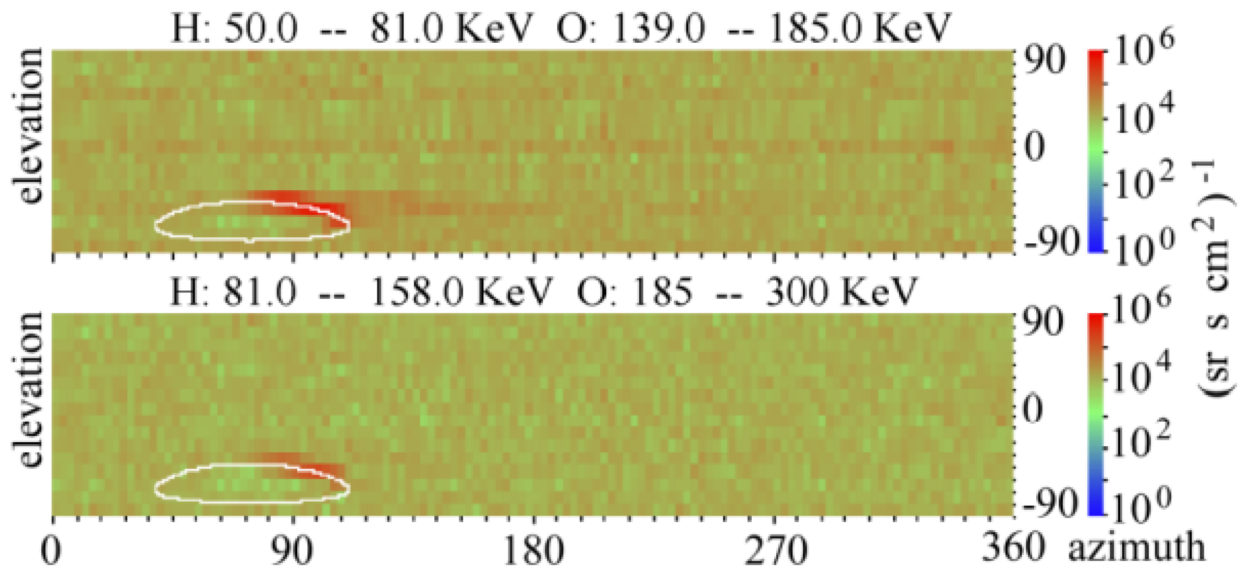
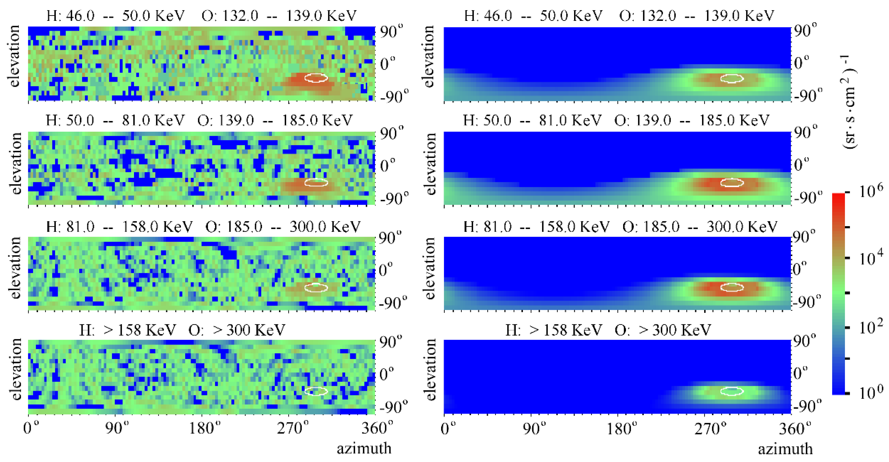
4.1. Instrumentation and Observations

The NUADU is equipped with 16 solid-state detectors (SSD), evenly distributed within a 180° elevation range. Each SSD has a field of view of 11.5° × 2.5° (for elevation and azimuth, respectively). The instrument scans in the azimuthal direction while the TC-2 satellite spins. During a full satellite spinning cycle of 4 s, the instrument performs 128 samplings with an integral time of 31.25 ms. Consequently, for each 4 s interval, the ENA counts can be binned into a matrix with 2048 grids (16 × 128). The ENA counts from multiple spin cycles may be further summed up by the onboard data processing unit to produce a final telemetry data frame. The instrument is usually configured to sum each 4-spin sample, which accounts for an integrated time of 125 ms. Deployment of the sixteen along satellite spinning axis is illustrated in Figure 4.
Because a mechanical collimator was used, the geometry factor of each SSD was fixed at 0.0125 cm2sr, which is independent of the particle mass and energy. To prevent pollution from geocoronal Lyman-a radiation, the instrument was wrapped with a layer of aluminum with a thickness of 200 nm. It was also equipped with high-voltage deflectors to prevent charged particles from impinging on the detectors. Because the high voltage was limited to 5000 V, charged particles with energies higher than 300 KeV were still able to transverse the deflecting electric field and enter the detectors. The deflecting electric field is likely to alter the energy of charged particles, causing particle pollution, which can reach all energy channels of the instrument.
NUADU counts ENAs without discriminating particle compositions while registering events for four energy levels according to the magnitude of responses in electronics. As most ions in the Earth’s ring current are H+ and O+, the instrument was calibrated against H and O. Table 1 presents the information for each energy channel of the instrument. The entire energy range covers the main part of the energy spectrum of the ring current ions.
Throughout the entire TC-2 mission, from August 2004 to July 2008, NUADU accumulated a dataset of volume greater than 29 GB, which laid the basis for subsequent scientific studies.

4.2. Review of Studies

Various methods have been applied to NUADU observations, which can be categorized into intuitive visual inspection, parameter analysis, forward modeling and comparison, and inversion.
(A)
Intuitive visual inspection
After data preprocessing, such as count-to-flux conversion, solar radiation and charged particle pollution mitigation, coordinate transformation, and satellite attitude correction, ENA fluxes are presented in 4π-solid-angle matrix plots, with the abscissa axis representing the azimuth direction and vertical axis for the elevation direction. In accordance with the elevation distribution of the detectors and the timing of ENA sampling, each matrix plot had 16 rows and 128 columns. All plots are presented with a satellite spin axis, presumably along the Z axis of the Solar Magnetic (SM) coordinate system, and the sun is in the zero-azimuth direction. Such an arrangement has the advantage of allowing people to intuitively perceive the source region distribution of ENAs, and to be further guided by a curve (colored white, Figure 5), indicating the limb of the Earth viewed from the satellite position.
Usually, only during strong magnetic storms is NUADU able to see significant ENA enhancements in its images. Chen et al. [53] selected the magnetic storm that occurred in November 2004, shortly after the launch of TC-2, when the satellite and the instrument were in good status. It was a very strong magnetic storm, as the minimum Dst reached −373 nT and lasted for more than five days. In their study, images taken near the magnetic poles and at different storm stages were visually inspected, focusing on the evolution of the ring’s current local time distribution. During the main phase of the magnetic storm, the ring current was strongly enhanced and confined to the dusk side of the Earth. When the storm developed into the recovery phase, in response to a northward turn of the interplanetary magnetic field (IMF), ENA fluxes gradually spread to other local times, indicating the formation of a symmetric ring current. Although images taken during the later recovery stage showed that the ring current had largely shrunk, the Dst was still at a very low level (i.e., a large negative value) and was compared to that of the main phase. This finding suggests that a strong magnetotail current, invisible to ENA detection, contributes to the magnetic disturbance indicated by the Dst index.
  • (B) Parameter analysis
A parameter deduced from ENA data can be useful for tracing the evolution of the ring current. Chen et al. [52] used the maximum flux of each ENA image to represent the overall ENA flux, which is rational because the maximum ENA flux always varies with the same trend as the overall flux. For both selected magnetic storms, the ENA fluxes of the four energy channels generally decreased with energy except at the end of the main phase when the flux of the third energy channel surpassed that of the second channel. This is consistent with a nondispersive earthward ion injection process driven by an enhanced magnetospheric electric field. Another significant feature of ENA flux variations during the Dst fast-recovery phase is an ascent interposed in the overall decreasing process. This is interpreted as a result of ion pileup at the dusk side when convection weakened upon entering the recovery phase. Because the parameterized ENA flux should be determined by a variety of factors apart from ring current ion fluxes, caution must be taken in interpreting it as an approximate measure of the overall ion flux to provide some insight.
  • (C) Forward modeling and comparison
To guide the development of NUADU, Shen and Liu [44] conducted a simulation study. Given an analytical ring current ion distribution and Chamberlain model of the geocorona [43], ENA fluxes can be calculated assuming arbitrary satellite positions. The main assumptions adopted by the model are the Kappa energy distribution and the empirically determined azimuth asymmetry for plasma-sheet ions at the injection boundary.
j i ( K 0 , φ 0 ) = j i   m a x   0 K 0 K i   m a x   0 ( 1 + 1 κ ) κ + 1 ( 1 + K 0 κ K i   m a x   0 ) κ 1 h ( φ 0 )
where K0 is the initial energy of the ions, and jimax0 and Kimax0 are the maximum differential flux and the corresponding characteristic energy of the ith ion species, respectively. Function h(ϕ0) modulates the ion flux for an asymmetric azimuth or local time distribution.
It was also assumed that ions experienced adiabatic motion, keeping the magnetic moment constant when injected from the plasma sheet into the ring current region. According to Liouville’s theorem, the ion flux at any position and pitch angle can be analytically determined.
Using the model described by Shen and Liu [44] and the same parameter set it took, Chen et al. [54,55] simulated real TC-2 satellite positions and compared the results with the ENA images captured by NUADU. There were significant discrepancies between the observations and simulations, particularly with regard to the local time distribution, latitudinal distribution, and energy spectrum. Comparisons between observed and simulated ENA images are shown in Figure 6. Keeping these discrepancies in mind, the author made some amendments to the model and got more consistent results. Major amendments include changing the Kappa energy spectrum to a Maxwellian one, replacing the fixed O+/H+ ratio with a varying ratio determined by the geomagnetic Kp index in according with the fact that the ratio of O+ may dramatically increase during magnetic storms [46], skewing ion injection front from the nightside to the dusk side of the Earth, adding oxygen and helium species to the neutral exosphere mode that made low altitude regions much more important in ENA production, and adding ENA stripping (re-ionizing) process to the mode assuming an optical-thick scenario. The updated mode and results were presented in his Ph.D. thesis [56].
In the new simulation, both the observed and simulated ENA images show flux enhancement very close to the limb of Earth, which is a new feature obtained after oxygen and helium species were added to the geocorona model. The oxygen and helium exosphere leads to a strong ENA emitting at very low heights of approximately 1000 km, where ions spiral down along geomagnetic field lines and interact with the dense atmosphere. This indicates that for ENA imaging, not only fluxes from the equatorial plane but also those from the high latitudes are significant, even when viewed from a relatively high satellite position. This type of low-altitude emission (LAE) has been studied by quite a few researchers [13,57]. D. Bazell et al. [57] drew a comparison between the LAE spectrum deduced from TWINS observations and that from DMSP in situ ion precipitation measurements, demonstrating ENA imaging as a promising method for monitoring dynamics in the aurora oval region. Chen et al. [55] once again highlighted the significance of LAE.
  • (D) Inversion
As direct ENA analysis is inevitably subject to ambiguity, and many factors may contribute to ENA counts, it is highly desirable to retrieve ion fluxes of the ring current from ENA imaging data. However, it is not possible to convert an integrated two-dimensional image into a three-dimensional distribution unless some assumptions and constraints are in place. Much effort has been devoted to this endeavor. Lu et al. [58,59] proposed a linearly constrained iterative inversion model to retrieve the global ring current ion distribution. In the model, the count in each pixel of an ENA image, Cδ,ε (pixel with elevation δ and azimuth ε), is represented by integration along the line of sight (LOS) of the instrument:
C δ , ε = d V Δ E Δ T Δ Ω A ( δ , ε ) Δ S [ j i o n H σ H ( E ) + j i o n O σ O ( E ) ] n
where dV is the volume element of the LOS of each pixel, ΔE is the energy range within which neutral atoms are detected, ΔT is the time period during which neutral atoms are accumulated, ΔΩ is the solid angle of the volume element pointing to the δ, ε pixels, A(δ, ε) is the response function of the detector for the pixel with elevation δ and azimuth ε, ΔS is the cross-section of the volume element perpendicular to the LOS, jionH and jionO are the unknown ion fluxes of hydrogen and oxygen, σH(E) and σO(E) are the respective charge-exchange cross sections between energetic hydrogen and oxygen ions and cold exospheric neutral atoms, and n is the exospheric neutral atom density near Earth.
Taking a numerical approach, the ENA count becomes:
C δ , ε = Δ T Δ E j , ( o r , k ) Δ Ω i , j , k A ( δ , ε ) S i , j , k j i , j , k * ( L , λ , φ , E , α ) σ * ( E ) n ( L , λ , φ ) i , j , k Δ l i , j , k
where i represents the ϕ coordinate, j is the λ coordinate, and k is the L coordinate of the volume element. A linear constrained iterative inversion method was used to guide the iteration direction by the error between the calculated and measured images to obtain the best inversion result.
Lu et al. [60] compared the inversion results with in situ measurements made by the LANL geostationary satellite. Good consistency demonstrated both the robustness of the inversion method and the reliability of the NUADU observations.
To study the ring current evolution process by applying the inversion model, Lu et al. [61] retrieved a sequence of global ion distributions with high spatial and temporal resolutions (approximately 4 min). In contrast to the conventional theory that ring current enhancements are the result of ion injections from the plasma sheet, it was found that in this instance, ring current enhancement occurred well before any ion injection. Despite this study producing significantly new results, further research is needed to confirm this conclusion.
Lu et al. [62,63] further improved the inversion temporal resolution to approximately 1 min and made it possible to exploit images recorded near the perigee of the satellite orbit, which otherwise would have been smeared owing to fast satellite motion. This should be a sequence of ion distributions retrieved from the ENA images with the highest temporal resolution. For a 10 min interval, during the recovery phase of a substorm, the enhancing and decaying processes of the ion flux of the ring current are clearly shown.

5. Conclusions

Charge exchange, a chemical process that occurs universally in space, plays an important role in the evolution of Earth’s ring current. It influences the ring current ion distributions and can now be sensed remotely.
Following other ENA imaging satellite missions, as a cooperative effort by China and the ESA, NUADU onboard the DSP has successfully operated for more than four years. Using NUADU data, studies ranging from intuitive visual inspection to more elaborate inversion methods have been conducted, and some valuable results have been obtained.
Chen et al. [53] presented the full evolution process of the ring current during a strong magnetic storm, in view of ENA images captured over the polar cap. Ion distributions and Dst variation were rationally represented by ENA images, albeit the contribution from magnetotail current to Dst may not visible in ENA observations. Using parameterized gross ENA flux to trace the development of storms, Chen et al. [52] found the phenomena of dispersive ion injection and a pileup of ions at the dusk side of the Earth that further complicated the topic of ion distribution and its evolution. Forward simulations and comparisons against observations have been done, coming out with an optimized mode [54,55]. The simulations revealed some important factors, such as the significance of LAE. A linear constrained iterative inversion method was devised and applied to NUADU observations [57,58,59]. The high time resolution (1 min) the inversion mode ultimately acquired made ENA imaging more promising for monitoring purposes [61,62]. The application of the mode to NUADU observations has revealed some interesting features such as ENA enhancement well before ion injection, although further confirmation is needed [60].
However, just as the complexities the above research has implied, there are a lot of open questions concerning the source, acceleration, loss mechanism, drift process, and many other aspects of ring current ions. Among them, the relationship between magnetic storms and substorm is remarkably controversial [63]. Some research holds that storm and substorm are independent, conceiving that ring current ion injection is driven by a large-scale convectional electric field rather than by inductive electric fields caused by geomagnetic field polarizations during substorms [64,65,66]. While some other research showed evidence, on the contrary, that ring current ions are accumulated by multiple substorm injection, that is to say, a storm embodies contributions from multiple substorms [67].
Furthermore, technically speaking, drawing definite augmentations from ENA images is challenging, because of the line-of-sight integration and many poorly determined factors that may also contribute. For example, there are few laboratory-based cross-sectional measurements available, and models for geocoronal density are not sufficiently accurate. For the imaging technique, it is also desirable to capture images with higher spatial and temporal resolutions and lower noise levels. Noise in images hinders a clear perception and may cause the inversion algorithm to be non-convergent or even invalid, whereas noise mitigation methods adopting multiple image integration will incur smearing due to the fast motion of the satellite.
ENA imaging is a developing technique, expanding its use to space regions other than the Earth’s ring current, such as the magnetosphere, heliosphere, and planetaries. China places much emphasis on this type of imaging technique, as it has conducted a successful lunar ENA measurement [68] and is aiming to image the Earth’s magnetosphere from around the moon [69], as well as on a lunar base [70]. China is also currently implementing a magnetosphere X-ray imaging mission, the SMILE program [71], which bears many similarities to ENA imaging with regard to algorithms. With further advances in technology and the deployment of more missions, the future of ENA imaging will enhance further space exploration.

Author Contributions

All authors listed have made a substantial, direct and intellectual contribution to the work, and approved it for publication. All authors have read and agreed to the published version of the manuscript.

Funding

This study was supported by the National Key R&D Program of China (2020YFE0202100) and the Basic Research Center of the National Science Foundation of China (42188101, 2022.01–2026.12).

Data Availability Statement

No new data were created or analyzed in this study. Data sharing is not applicable to this article.

Conflicts of Interest

The authors declare no conflict of interest.

References

  1. Schulz, M. The Magnetosphere—ScienceDirect. Geomagnetism 1991, 25, 87–293. [Google Scholar]
  2. Maggiolo, R.; André, N.; Hasegawa, H.; Welling, D.T.; Zhang, Y.; Paxton, L.J. Magnetospheres in the Solar System; AGU: Washington, DC, USA, 2021. [Google Scholar] [CrossRef]
  3. Roederer, J.G. Dynamics of Geomagnetically Trapped Radiation; Springer: New York, NY, USA, 1970. [Google Scholar]
  4. Williams, D.J. Ring current and radiation belt. Rev. Geohpys. 1987, 25, 570–578. [Google Scholar] [CrossRef]
  5. Pfaff, R.F.; Borovsky, J.E.; Young, D.T. Measurement techniques in space plasmas: Fields. Geophys. Monogr. Ser. 1998, 103. [Google Scholar]
  6. Pfaff, R.F.; Borovsky, J.E.; Young, D.T. Measurement techniques in space plasmas: Particles. Geophys. Monogr. Ser. 1998, 102. [Google Scholar]
  7. Daglis, I.A.; Thorne, R.M.; Baumjohann, W.; Orsini, S. The terrestrial ring current: Origin, formation, and decay. Rev. Geophys. 1999, 37, 407–438. [Google Scholar] [CrossRef]
  8. Ogilvie, K.W.; von Rosenvinge, T.; Durney, A.C. International Sun-Earth Explorer: A Three-Spacecraft Program. Science 1977, 198, 131–138. [Google Scholar] [CrossRef]
  9. Nishida, A.; Uesugi, K.; Nakatani, I.; Mukai, T.; Fairfield, D.H.; Acuna, M.H. Geotail Mission to explore Earth’s magnetotail. Eos Trans. AGU 1992, 73, 425–429. [Google Scholar] [CrossRef]
  10. Blake, J.B.; Fennell, J.F.; Friesen, L.M.; Johnson, B.M.; Kolasinski, W.A.; Mabry, D.J.; Osborn, J.V.; Penzin, S.H.; Schnauss, E.R.; Spence, H.; et al. CEPPAD. Space Sci. Rev. 1995, 71, 531–562. [Google Scholar] [CrossRef]
  11. Roelof, E.C.; Mitchell, D.G.; Williams, D.J. Energetic Neutral Atoms (E∼50 KeV) from the Ring Current: IMP 7/8 and ISEE 1. J. Geophys. Res. 1985, 90, 10991–10998. [Google Scholar] [CrossRef]
  12. Johnson, M.H.; Kierein, J.W. Combined Release and Radiation Effects Satellite (CRRES): Spacecraft and Mission. J. Spacecr. Rocket. 1992, 29, 556–563. [Google Scholar] [CrossRef]
  13. Brandt, P.C.; Barabash, P.S.; Norberg, O.; Lundin, R.; Roelof, E.C.; Chase, C.J.; Mauk, B.H.; Thomsen, M. ENA imaging from the Swedish microsatellite Astrid: Images and spectral analysis. J. Geophys. Res. 1999, 104, 2367–2379. [Google Scholar] [CrossRef]
  14. Burch, J.L. IMAGE mission overview. Space Sci. Rev. 2000, 91, 1–14. [Google Scholar] [CrossRef]
  15. McComas, D.; Goldstein, J. The two wide-angle imaging neutral-atom spectrometers (TWINS) NASA mission-of-opportunity. Space Sci. Rev. 2009, 142, 157–231. [Google Scholar] [CrossRef] [Green Version]
  16. Ma, S.-Y.; Yan, W.-N.; Xu, L. Tomographic reconstruction of storm time RC ion distribution from ENA images on board multiple spacecraft. J. Geophys. Res. Space Phys. 2016, 120, 9334–9354. [Google Scholar] [CrossRef] [Green Version]
  17. Matson, D.L.; Spilker, L.J.; Lebreton, J.P. The Cassini/Huygens Mission to the Saturnian System. In The Cassini-Huygens Mission; Springer: Berlin/Heidelberg, Germany, 2003; pp. 1–58. [Google Scholar]
  18. Mccomas, D.J.; Allegrini, F.; Bochsler, P.; Bzowski, M.; Collier, M.; Fahr, H.; Fichtner, H.; Frisch, P.; Funsten, H.O.; Fuselier, S.A.; et al. Ibex-interstellar boundary explorer. Space Sci. Rev. 2009, 146, 11–33. [Google Scholar] [CrossRef] [Green Version]
  19. Mitchell, D.G.; Brandt, P.C.; Westlake, J.H.; Jaskulek, S.E.; Andrews, G.B.; Nelson, K.S. Energetic particle imaging: The evolution of techniques in imaging high-energy neutral atom emissions. J. Geophys. Res. Space Phys. 2016, 121, 8804–8820. [Google Scholar] [CrossRef]
  20. Lukyanov, A.V.; Barabash, S.; Holmstrom, M. Energetic neutral atom imaging at Mercury. Adv. Space Res. 2004, 33, 1890–1898. [Google Scholar] [CrossRef]
  21. Brandt, P.C.; Hsieh, S.Y.; Demajistre, R.; Mitchell, D.G. ENA Imaging of Planetary Ring Currents. In Electric Currents in Geospace and Beyond, American Geophysical Union Geophysical Monograph 235; Andreas, K., Octav, M., Michael, W., American, G., Eds.; John Wiley & Sons, Inc.: New York, NY, USA, 2018; pp. 95–113. [Google Scholar]
  22. Gruntman, M. Energetic Neutral Atom Imaging of Space Plasmas. Rev. Sci. Instrum. 1997, 68, 3617–3656. [Google Scholar] [CrossRef] [Green Version]
  23. Liu, Z.X.; Escoubet, C.P.; Pu, Z.; Laakso, H.; Shi, J.K.; Shen, C.; Hapgood, M. The Double Star Mission. Ann. Geophys. 2005, 23, 2707–2712. [Google Scholar] [CrossRef]
  24. Shen, C.; Liu, Z.-X. Double Star Project Master Science Operations Plan. Ann. Geophys. 2005, 23, 2851–2859. [Google Scholar] [CrossRef]
  25. Escoubet, C.P.; Russell, C.T.; Schmidt, R. (Eds.) The Cluster and Phoenix Missions; Springer Dordrecht: Berlin/Heidelberg, Germany, 1997; Volume 79. [Google Scholar]
  26. McKenna-Lawlor, S.; Balaz, J.; Barabash, S.; Johnsson, K.; Li, L.; Shen, C.; Shi, J.; Zong, Q.; Kudela, K.; Fu, S.; et al. The energetic NeUtral Atom Detector Unit (NUADU) for China’s Double Star Mission and its calibration. Nucl. Inst. Methods A 2004, 503, 311–322. [Google Scholar] [CrossRef]
  27. McKenna-Lawlor, S.; Balaz, J.; Barabash, S.; Johnsson, K.; Li, L.; Shen, C.; Shi, J.; Zong, Q.; Kudela, K.; Fu, S.; et al. An overview of the scientific objectives and technical configuration of the NeUtral Atom Detector Unit NUADU for the Chinese Double Star Mission. Planet. Space Sci. 2005, 53, 335–348. [Google Scholar] [CrossRef]
  28. McCormac, B.M. Magnetospheric Physics; D. Reidel Publishing Company: Dordrecht, The Netherlands, 1974. [Google Scholar]
  29. Ohtani, S.I.; Fujii, R.; Hesse, M.; Lysak, R.L. Magnetospheric Current Systems; AGU: Washington, DC, USA, 2000; Volume 118. [Google Scholar]
  30. Jordan, C.E. Empirical models of the magnetospheric magnetic field. Rev. Geophys. 1994, 32, 139–157. [Google Scholar] [CrossRef]
  31. Rossi, B.; Olbert, S. Introduction to the Physics of Space; McGraw-Hill Book Company: New York, NY, USA, 1970; pp. 133–146. [Google Scholar]
  32. Shen, C.; Yang, Y.Y.; Rong, Z.J.; Li, X.; Dunlop, M.; Carr, C.M.; Liu, Z.X.; Baker, D.N.; Chen, Z.Q.; Ji, Y.; et al. Direct calculation of the ring current distribution andmagnetic structure seen by Cluster during geomagnetic storms. J. Geophys. Res. Space Phys. 2014, 119, 2458–2465. [Google Scholar] [CrossRef]
  33. Shen, C.; Zeng, G.; Li, X.; Rong, Z.J. Evolution of the storm magnetic field disturbance around Earth’s surface and the associated ring current as deduced from multiple ground observatories. J. Geophys. Res. Space Phys. 2015, 120, 564–580. [Google Scholar] [CrossRef]
  34. Yang, Y.Y.; Shen, C.; Dunlop, M.; Rong, Z.J.; Li, X.; Angelopoulos, V.; Chen, Z.Q.; Yan, G.Q.; Ji, Y. Storm time current distribution in the inner equatorial magnetosphere: THEMIS observations. J. Geophys. Res. Space Phys. 2016, 121, 5250–5259. [Google Scholar] [CrossRef] [Green Version]
  35. Shen, C.; Liu, Z.X.; Kamei, T. A Physics Based Study of the Dst-AL Relationship. J. Geophys. Res. 2002, 107, SMP-4. [Google Scholar] [CrossRef]
  36. Dessler, A.J.; Parker, E.N. Hydromagnetic theory of geomagnetic storms. J. Geophys. Res. 1959, 64, 2239–2252. [Google Scholar] [CrossRef]
  37. Sckopke, N. A general relation between the energy of trapped particles and the disturbance field near the Earth. J. Geophys. Res. 1966, 71, 3125–3130. [Google Scholar] [CrossRef]
  38. Akasofu, S.I.; Chapman, S. The ring current, geomagnetic disturbance, and the Van Allen belts. J. Geophys. Res. 1961, 66, 1321–1350. [Google Scholar] [CrossRef] [Green Version]
  39. Gonzalez, W.D.; Joselyn, J.A.; Kamide, Y.; Kroehl, H.W.; Rostoker, G.; Tsurutani, B.T.; Vasyliunas, V.M. What is a geomagnetic storm? J. Geophys. Res. 1994, 99, 5771–5792. [Google Scholar] [CrossRef] [Green Version]
  40. Chapman, S.; Bartels, J. Geomagnetism; Oxford University Press: Oxford, UK, 1940; p. 1049. [Google Scholar]
  41. Toshihiko, I. Storm-Time Magnetospheric Currents Inferred from Mid-Latitude Geomagnetic Field Variations. J. Geomag. Geoelectr. 1990, 42, 1249–1265. [Google Scholar]
  42. Sandel, B.R.; King, R.A.; Forrester, W.T.; Gallagher, D.L.; Broadfoot, A.L.; Curtis, C.C. Initial results from the IMAGE extreme ultraviolet imager. Geophys. Res. Lett. 2001, 28, 1439. [Google Scholar] [CrossRef]
  43. Chamberlain, J.W. Planetary coronae and atmospheric evaporation. Planet. Space Sci. 1963, 11, 901–960. [Google Scholar] [CrossRef]
  44. Shen, C.; Zhenxing, L. Energetic neutral atom imaging of the Earth’s ring current region. Chin. J. Geophys. 2003, 46, 1–10. [Google Scholar]
  45. Xie, L.; Pu, Z.Y.; Zhou, X.-Z.; Fu, S.Y.; Zong, Q.-G.; Hong, M.H. Energetic ion injection and formation of the storm-time symmetric ring current. Ann. Geophys. 2006, 24, 3547–3556. [Google Scholar] [CrossRef] [Green Version]
  46. Fu, S.-Y.; Pu, Z.-Y.; Zong, Q.-G.; Xiao, C.-J.; Xie, L.; Wilken, B. Ion composition variations in the ring current during intense magnetic storms and their relationship with evolution of storms. Chin. J. Geophys. 2001, 44, 1–12. [Google Scholar] [CrossRef]
  47. Nosé, M.; Taguchi, S.; Hosokawa, K.; Christon, S.P.; McEntire, R.W.; Moore, T.E.; Collier, M.R. Overwhelming O+ contribution to the plasma sheet energy density during the October 2003 superstorm: Geotail/EPIC and IMAGE/LENA observations. J. Geophys. Res. 2005, 110, A09S24. [Google Scholar] [CrossRef]
  48. Fahr, H.J.; Fichtner, H.; Scherer, K. Theoretical aspects of energetic neutral atoms as messengers from distant plasma sites with emphasis on the heliosphere. Rev. Geophys. 2007, 45, RG4003. [Google Scholar] [CrossRef] [Green Version]
  49. McKenna-Lawlor, S.; Li, L.; Barabash, S.; Kudela, K.; Balaz, J.; Strharsky, I.; Brinkfeldt, K.; Gunell, H.; Shen, C.; Shi, J.; et al. The NUADU experiment on TC-2 and the first Energetic Neutral Atom (ENA) images recorded by this instrument. Ann. Geophys. 2005, 23, 2825–2849. [Google Scholar] [CrossRef]
  50. Lindsay, B.G.; Stebbings, R.F. Charge transfer cross sections for energetic neutral atom data analysis. J. Geophys. Res. 2005, 110. [Google Scholar] [CrossRef]
  51. Bishop, J. Multiple charge exchange and ionization collisions within the ring current-geocorona-plasmasphere system: Generation of a secondary ring current on inner L. shells. J. Geophys. Res. 1996, 101, 17325–17336. [Google Scholar] [CrossRef]
  52. Chen, Z.Q.; Shen, C.; Lu, L.; Mckenna Lawlor, S.; Liu, Z.X.; Yan, G.Q. Study on the Earth ring current during magnetic storms based on energetic neutral atom flux data. Chin. J. Geophys. 2012, 55, 727–737. (In Chinese) [Google Scholar] [CrossRef]
  53. Chen, Z.Q.; Shen, C.; Lu, L.; McKenna-Lawlor, S.; Liu, Z.X.; Yan, G.Q. Evolvement of the ring current during a magnetic storm: TC-2 neutral atom imager observations. Chin. J. Geophys. 2010, 53, 2271–2279. (In Chinese) [Google Scholar] [CrossRef]
  54. Zhiqing, C.; Chao, S.; Li, L.; McKenna-Lawlor, S.; Zhenxing, L.; Guangqing, Y. Energetic neutral atom imaging of the earth ring current during magnetic storms—Comparison between simulation results and observation. Chin. J. Space Sci. 2012, 32, 182–190. [Google Scholar]
  55. Chen, Z. Detection of Storm-Time Ring Current by Neutral Atom Imager Onboard TC-2 of Double Star Program. Ph.D. Thesis, University of Chinese Academy of Sciences, Beijing, China, 2011. (In Chinese). [Google Scholar]
  56. Bazell, D.; Roelof, E.; Sotirelis, T.; Brandt, P.; Nair, H.; Valek, P.; Goldstein, J.; McComas, D. Comparison of TWINS Images of Low-Altitude Emission of Energetic Neutral Atoms with DMSP Precipitating Ion Fluxes. J. Geophys. Res. 2010, 115, 1–17. [Google Scholar] [CrossRef] [Green Version]
  57. Li, L.; McKenna-Lawlor, S.; Barabash, S.; Balaz, J.; Strharsky, I.; Liu, Z.; Shen, C.; Kudela, K.; Brandt, P.; Tang, C.L. Iterative inversion of global magnetospheric ion distributions using energetic neutral atom (ENA) images recorded by the NUADU/TC2 instrument. Ann. Geophy. 2008, 26, 1641–1652. [Google Scholar]
  58. Li, L.; Mckenna, L.; Barabash, S.; Balaz, J.; Liu, Z.; Shen, C.; Cao, J.B.; JinBin, C.; Tang, C.L. Iterative inversion of global magnetospheric information from energy neutral atom (ENA) images recorded by the TC-2/NUADU instrument. Sci. China Technol. Sci. 2008, 51, 1731–1744. [Google Scholar]
  59. Lu, L.; McKenna-Lawlor, S.; Barabash, S.; Brandt, P.; Balaz, J.; Liu, Z.X.; He, Z.H.; Reeves, G. Comparisons between ion distributions retrieved from ENA images of the ring current and contemporaneous, multipoint ion measurements recorded in situ during the major magnetic storm of 15 May 2005. J. Geophys. Res. 2010, 115, A12218. [Google Scholar] [CrossRef] [Green Version]
  60. Lu, L.; McKenna-Lawlor, S.; Cao, J.; Kudela, K.; Balaz, J. The causal sequence investigation of the ring current ion-flux increasing and the magnetotail ion injection during a major storm. Sci. China Earth Sci. 2015, 59, 129–144. [Google Scholar] [CrossRef]
  61. Lu, L.; McKenna-Lawlor, S.; Balaz, J. Close up observation and inversion of low-altitude ENA emissions during a substorm event. Sci. China Earth Sci. 2019, 62, 1024–1032. [Google Scholar] [CrossRef]
  62. Lu, L.; Yu, Q.-L.; Lu, Q. Near-Approach Imaging Simulation of Low-Altitude ENA Emissions by a LEO Satellite. Front. Astron. Space Sci. 2020, 7, 35. [Google Scholar] [CrossRef]
  63. Kamide, Y.; Baumjohann, W.; Daglis, I.; Gonzalez, W.D.; Grande, M.; Joselyn, J.A.; McPherron, R.; Phillips, J.L.; Reeves, G.; Rostoker, G.; et al. Current understanding of magnetic storms: Storm-substorm relationships. J. Geophys. Res. 1998, 103, 17705–17728. [Google Scholar] [CrossRef]
  64. Grafe, A.; Feldstein, Y.I. About the relationship between auroral electrojets and ring current. Ann. Geophys. 2000, 18, 874–886. [Google Scholar] [CrossRef]
  65. Mcpherron, R.L. The role of substorm in generation of magnetic storms. Geophys. Monogr. 1997, 98, 131–147. [Google Scholar]
  66. Iyemori, T.; Rao, D.R.K. Decay of the Dst field of geomagnetic disturbance after substorm onset and its implication to storm-substorm relation. Ann. Geophys. 1996, 14, 608–618. [Google Scholar] [CrossRef]
  67. Brandt, P.; Ohtani, S.; Mitchell, D.; Demajistre, R. Storm—Substorm relationships during the 4 October, 2000 storm. IMAGE global ENA imaging results. Geophys. Monogr. 2003, 142, 103–117. [Google Scholar]
  68. Wieser, M.; Barabash, S.; Wang, X.-D.; Grigoriev, A.; Zhang, A.; Wang, C.; Wang, W. The Advanced Small Analyzer for Neutrals (ASAN) on the Chang’E-4 Rover Yutu-2. Space Sci. Rev. 2020, 216, 73. [Google Scholar] [CrossRef]
  69. Yongliao, Z.; Yang, L.; Yingzhuo, J. Overview of China’s Upcoming Chang’E Series and the Scientific Objectives and Payloads for Chang’E 7 Mission. In Proceedings of the 51st Lunar and Planetary Science Conference, Woodlands, TX, USA, 16–20 March 2020. [Google Scholar]
  70. Li, L.; Qing-Long, Y.; Ping, Z.; Xin, Z.; Xian-Guo, Z.; Xin-Yue, W.; Yuan, C. Simulation study of the energetic neutral atom (ENA) imaging monitoring of the geomagnetosphere on a lunar base. Sol.-Terr. Phys. 2021, 7, 3–11. [Google Scholar] [CrossRef]
  71. Wang, C.; Branduardi-Raymond, G. Progress of Solar Wind Magnetosphere Ionosphere Link Explorer (SMILE) Mission. Chin. J. Space Sci. 2018, 38, 657–661. [Google Scholar] [CrossRef]
Figure 1. The magnetospheric convection denoted by drift paths of energetic ions. (Figure adapted from Yuting Ng).
Magnetochemistry 09 00029 g001
Figure 2. Scheme depicting the charge-exchange process [49]. An electron is transferred from an hydrogen atom to an oxygen energetic ion on collision (A), and the oxygen energetic ion changes into an ENA and flies away keeping velocity unchanged (B).
Magnetochemistry 09 00029 g002
Figure 3. Cross section between ions (left: H+, right: O+) and geocoronal atoms.
Magnetochemistry 09 00029 g003
Figure 4. Field of view of a single detector and pointing directions of the detectors. By attitude control, the satellite spinning axis was usually maintained in vicinity of the Z axis of the Solar Magnetic (SM) coordinate system with +Z pointing northward.
Magnetochemistry 09 00029 g004
Figure 5. Examples of ENA images (7 November 2004 23:36:16 UT) [52].
Magnetochemistry 09 00029 g005
Figure 6. Comparison between the observed (left) and the simulated (right) images, for 8 November 2004 03:53:37 UT. [55].
Magnetochemistry 09 00029 g006
Table 1. Energy channels of NUADU.
ChannelHO
Ch146–50 keV132–139 keV
Ch250–81 keV139–185 keV
Ch381–158 keV185–300 keV
Ch4158–∞ keV300–∞ keV
Disclaimer/Publisher’s Note: The statements, opinions and data contained in all publications are solely those of the individual author(s) and contributor(s) and not of MDPI and/or the editor(s). MDPI and/or the editor(s) disclaim responsibility for any injury to people or property resulting from any ideas, methods, instructions or products referred to in the content.

