Article

Cluster Observation of Ion Outflow in Middle Altitude LLBL/Cusp from Different Origins

1
MNR Key Laboratory for Polar Science, Polar Research Institute of China, Shanghai 200136, China
2
Institute of Space Physics and Applied Technology, Peking University, Beijing 100871, China
3
ESA/ESTEC SCI-S, 2200 AG Noordwijk, The Netherlands
4
School of Telecommunication and Information Engineering, Xi’an University of Posts and Telecommunications, Xi’an 710121, China
*
Authors to whom correspondence should be addressed.
Magnetochemistry 2023, 9(2), 39; https://doi.org/10.3390/magnetochemistry9020039
Submission received: 15 December 2022 / Revised: 16 January 2023 / Accepted: 17 January 2023 / Published: 20 January 2023
(This article belongs to the Special Issue Magnetodynamics of Space Plasmas)

Abstract

:
The ionosphere is the ionized part of the upper atmosphere that is caused mainly by photoionization by solar extreme ultraviolet (EUV) emission and the atmospheric photochemistry process. The ionospheric ions escape from the ionosphere and populate the Earth’s magnetosphere. In this case study, ion outflows from two different origins were obtained by spacecraft Cluster C1 in the magnetospheric cusp region. One of the outflows was from the reflection of the dispersed solar wind particles. The other was the ionospheric outflow passing through the low latitude boundary layer of the cusp (LLBL/cusp), which was energized by downward Poynting flux. Similar to the reflected solar wind particles, outflowing ionospheric cold ions could also extend to the high-latitude region with magnetic field line convection, which mixed it up with solar wind particles. Based on the Cluster observation in the cusp region, two different origins of the outflowing particles were determined, and their unique mechanisms of formation were discussed. Results suggest that the strong electric field associated with solar wind particle precipitation may additionally accelerate the cold ionospheric ion flow in the LLBL/cusp.

1. Introduction

The ionized part of the upper atmosphere (ionosphere) is caused mainly by photoionization by solar EUV emission and the atmospheric photochemistry process. The ionospheric ions escape from the ionosphere and populate the Earth’s magnetosphere. The Earth’s magnetic cusp is a funnel-like region where solar wind plasma can directly enter into the ionosphere from the reconnection sites. During southward interplanetary magnetic field (IMF), reconnection happens near the subsolar region of the magnetopause [1,2]. Newly opened magnetic field lines convert tailward and disperse frozen-in particles into cusp and polar cap. As high-energy ions move faster, more high-energy ions can be detected on the low latitude of the cusp, and slower-moving lower-energy ions precipitate at the high-latitude side of the cusp with tailward moving of magnetic field lines. Previous researchers named this process the velocity filter effect [3,4]. As geomagnetic field lines converge at the cusp, parts of downward-moving ions would be reflected from the magnetic mirror point due to the magnetic mirror force if they did not dissipate into the ionosphere. The reflected and upflowing ionospheric ions are named as polar wind [5,6,7]. What makes the ionospheric ions flow outward is one of the essential issues of magnetosphere–ionosphere coupling research. Sheeley et al. [8] discovered a copious amount of keV-range oxygen and hydrogen ions flowing out of the ionosphere along magnetic field lines, which are referred to as ‘ion beams’. Sharp et al. [9] found that O+ ions with energies of approximately 1 keV in the ionosphere have a minimum in pitch angle distribution along the magnetic field and a maximum in about the 130–140° range, which is referred as ‘ion conics’ in later research. Gorney et al. [10] compared the occurrence probability of ion beams and conics at 0.09–3.9 keV observed on S3-3 over all local time above 54° invariant in 1976, and showed a gradual increase in the occurrence of beams. In contrast, the occurrence of conics kept stable in the altitude range of the study (below 8000 km). Yau and Andre [11] summarized the sources of ion outflow in the high-latitude ionosphere and mentioned that the observed ion distribution at a given altitude often consists of ions from more than one source. Due to ion convection and gradual heating as the different sources of ions move upward, it is not always possible to delineate the contributions from the respective source in an observed distribution. Bouhram et al. [12,13,14,15] showed the observation and the modeling of ion outflow and associated perpendicular heating and compared the altitude dependence of oxygen ion conics in the dayside cusp/cleft region from the Akebono, Interball-2 and Cluster over a continuous and broad altitude range up to about 5.5 Earth radii (RE). The study confirmed that transverse ion heating in the cusp/cleft is height-integrated at radial distances below 4 RE, and saturation of transverse heating processes occurs above 4.5 RE. Lindstedt et al. [16] reported Cluster observations of oxygen energization by several keV at the boundary between the high-latitude cusp and lobe and found that a localized electric field at the cusp/lobe boundary is responsible for a significant part of the observed energization. Nilsson et al. [17] showed and discussed Cluster observations of the spatial distribution of ions and wave activity in the high-altitude polar cap and found that it is suitable to divide the ion outflow paths into three distinct regions: the cusp, the central polar cap and the night-side polar cap. Liao et al. [18] compared the distribution function of streaming O+ in the tail lobes with the initial distribution function observed over the cusp and revealed that the observations of energetic streaming O+ in the lobes around 20 RE are predominantly due to the velocity filter effect during non-storm times. During storm times, the cusp distribution is further accelerated. Unlike electron inverted-V acceleration [19,20,21], the dominant ion outflow is related to the lower-frequency ELF and Alfvenic wave activity [22,23,24]. The most energetic ion conics are also coincident with broadband enhancements in the wave power, as reported by André et al. [23,25], Jacobsen and Moen [26], Slapak et al. [27] and Waara et al. [28].
Different from the discrete aurora region on the aurora oval, almost no monoenergetic inverted-V–type electrons or ions can be observed along the magnetic field line in the cusp region. The precipitation and outflow of the particles are mainly controlled by dayside reconnection, magnetic line convection, and wave heating. During the Cluster 20 anniversary, Pitout and Bogdanova [29] reviewed 20 years of cusp research with the Cluster mission. A multi-point capability, appropriate orbits, and comprehensive instrumentation made Cluster the ideal space mission to study the cusp. Iannis Dandouras [30] reviewed some observations of outflowing and escaping ion populations performed by Cluster in the magnetosphere during the past 20 years. Among past research, ions outflow from ionosphere origin and solar wind reflection is rarely distinguished. In this study, based on a Cluster detailed observation, a picture with fine-structured cusp ion precipitation and cold ion outflow is presented. Different origins of the outflowing particles are determined, and unique outflowing mechanisms are discussed. A mechanism for the cold ion’s pitch angle upward turning on low latitude boundary layer (LLBL/cusp) was discussed. The LLBL mentioned in this paper is defined as a layer on the equatorial side of the cusp, where plasma diffusion across the magnetopause and cusp is restricted by more or less direct entry [31,32,33].

2. Observations

Investigations of the solar wind–magnetosphere coupling and the shocked solar wind penetration through the polar cusps were one of the main science objectives of the Cluster mission [34]. In this case study, we mainly use data from the Electric Field and Wave instrument (EFW) [35], the Fluxgate Magnetometer (FGM) [36] and the Cluster Ion Spectrometry (CIS) instrument [37] on Cluster C1. The OMNI data are used to show the solar wind and geomagnetic conditions.

2.1. Solar Wind Parameters and Spacecraft Orbit

Figure 1 shows Interplanetary Magnetic Field (IMF) Bz component in the GSM coordinate (Figure 1a), solar wind dynamic pressure (Figure 1b) and the AE index (Figure 1c) between 16:00 and 18:00 UT on 23 August 2004 based on the OMNI dataset. The event we are interested in was observed by Cluster C1 between 17:00 and 17:20 UT. During this time interval, IMF Bz was keeping weak southward, while solar wind dynamic pressure was quite stable. Southward IMF Bz and stable flow pressure would trigger magnetic reconnection between the geomagnetic field and IMF at the dayside magnetopause. With the development of the dayside reconnection, the newly opened magnetic field line convected tailward with solar wind, which produced particle dispersion observed in the cusp region in this study.
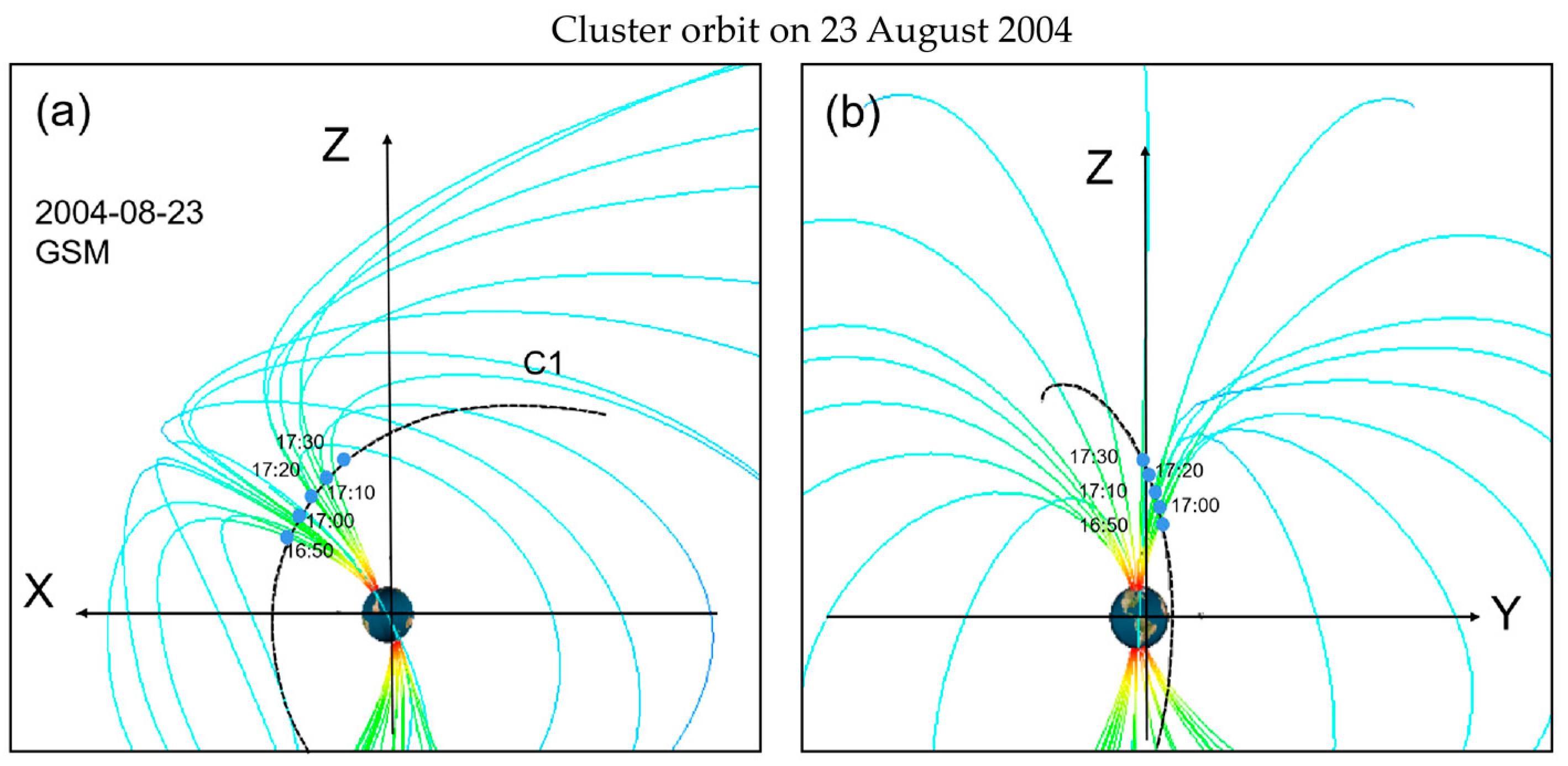
Figure 2a,b show the Cluster orbit of the event along with the magnetic field configuration obtained based on the T96 model in the X–Z plane and the Y–Z plane in the Geocentric Solar Magnetospheric (GSM) coordinate, respectively. It is shown that Cluster C1 passed through the northern cusp at about 17:06 UT around noon from low latitude to high latitude, which provides an excellent opportunity to study the cusp particle composition variation along latitudes. During the period between 17:00 and 17:20 UT on 23 August 2004, C1 crossed the northern cusp from 77° to 80° ILAT at about 4.8 RE of geocentric distance and around MLT 13.2.

2.2. Particle Differential Energy Flux

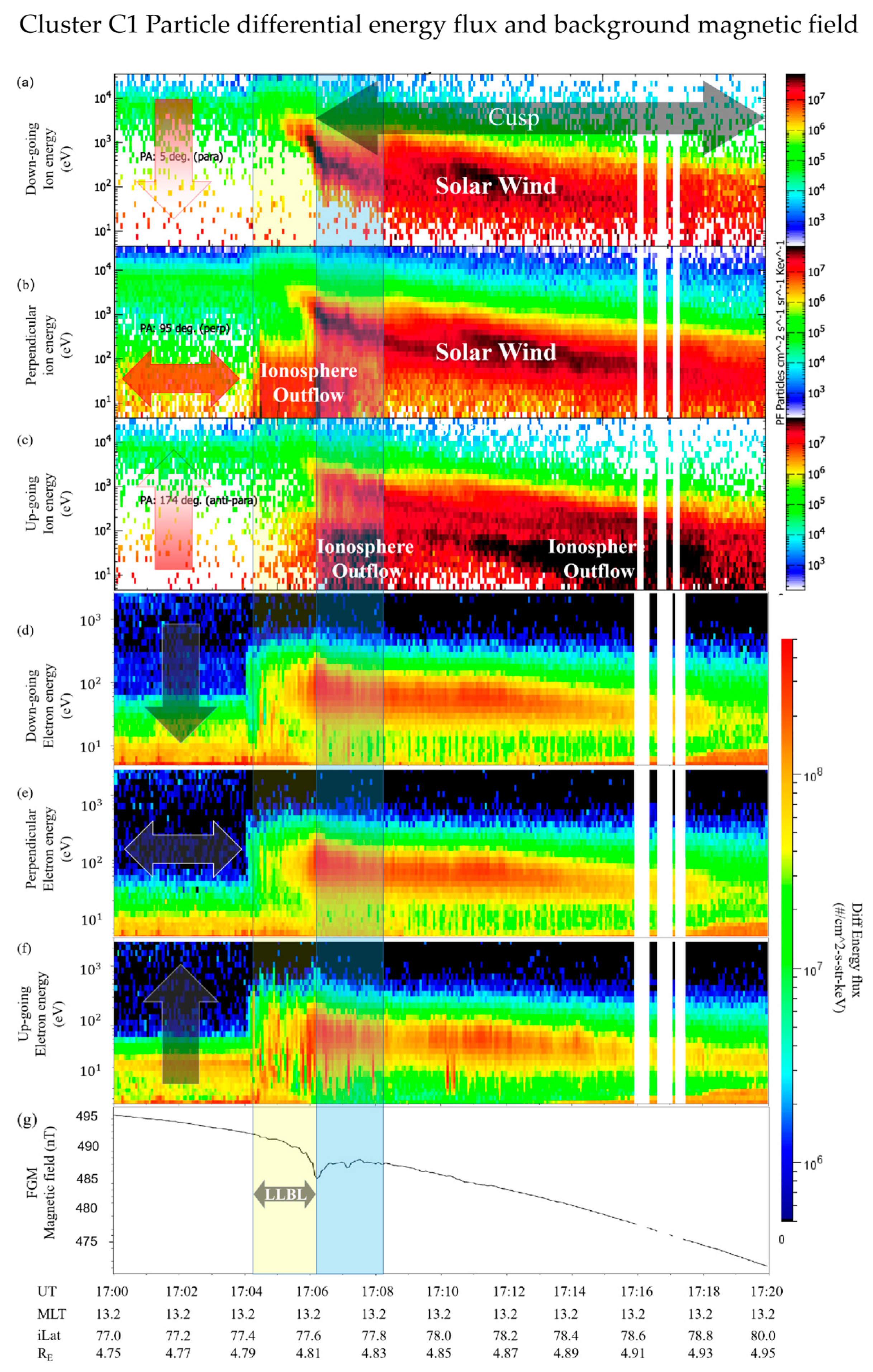
Figure 3a shows an example of the velocity filter effect that can be observed in cusp ion distribution during low-latitude magnetic reconnection conditions. In this event, keV down-going ions were observed first at about 17:05 UT, corresponding to a local decrease in the magnetic field for about 5 nT. These two features combined with the spacecraft orbit indicated that Cluster C1 passed a cusp region. With C1 moving to high latitude, ion energy decreases to hundreds of eV or lower, indicating that the low-energy ion moves down slower along magnetic field lines. When the newly opened field lines convect to high latitudes, low-energy particles then can be detected by C1. Figure 3b,c show ion fluxes perpendicular and anti-parallel to the background magnetic field lines detected by CIS onboard C1, similar to the downflowing flux, which also presents a dispersion signature with increasing latitudes in higher energies. Fuselier et al. [35] discussed the source of precipitation population for the cusp and cleft/LLBL for southward IMF, based on the assumption that the distinction between the cusp and LLBL precipitation can be explained as a natural consequence, and magnetic reconnection at the dayside magnetopause, a break in the energy spectrum for individual spectra from the dayside high-latitude region, is reproduced at ~3 keV/e. In this event, a break in the down-going ion spectrum can also be found near UT 17:06, which is regarded as the boundary between LLBL and the cusp. Bogdanova et al. [38] presented results of a statistical study of the electron edge of the LLBL observed by Cluster during mid-altitude cusp crossings and found that inside the electron edge there are low-energy heated ions from the ionosphere accompanied by ions of magnetosphere origin, and these characteristics can be observed in this study as well.
Besides those keV to hundreds eV ion energy dispersion features in the cusp, some cold ion distribution was observed. In Figure 3b, between 17:04 and 17:06 UT (yellow shadow region), a strong flux of cold ions with energy between 5.5 eV and 100 eV was detected at the LLBL in the perpendicular direction. Following that, upflowing cold ions in the same energy range were captured between 17:06 and 17:08 UT (green shadow region) in Figure 3c. The switch of the cold ion’s pitch angle occurring at the local minimum of the geomagnetic field (Figure 3g) can be regarded as the low-latitude edge of the cusp. In the electron spectrum data, in Figure 3d–f, an electron boundary can be observed at the equatorial side of the LLBL at 17:04 UT, which can be regarded as the low-latitude open–close field line boundary [38,39].

2.3. The Composition of Outflowing Ions

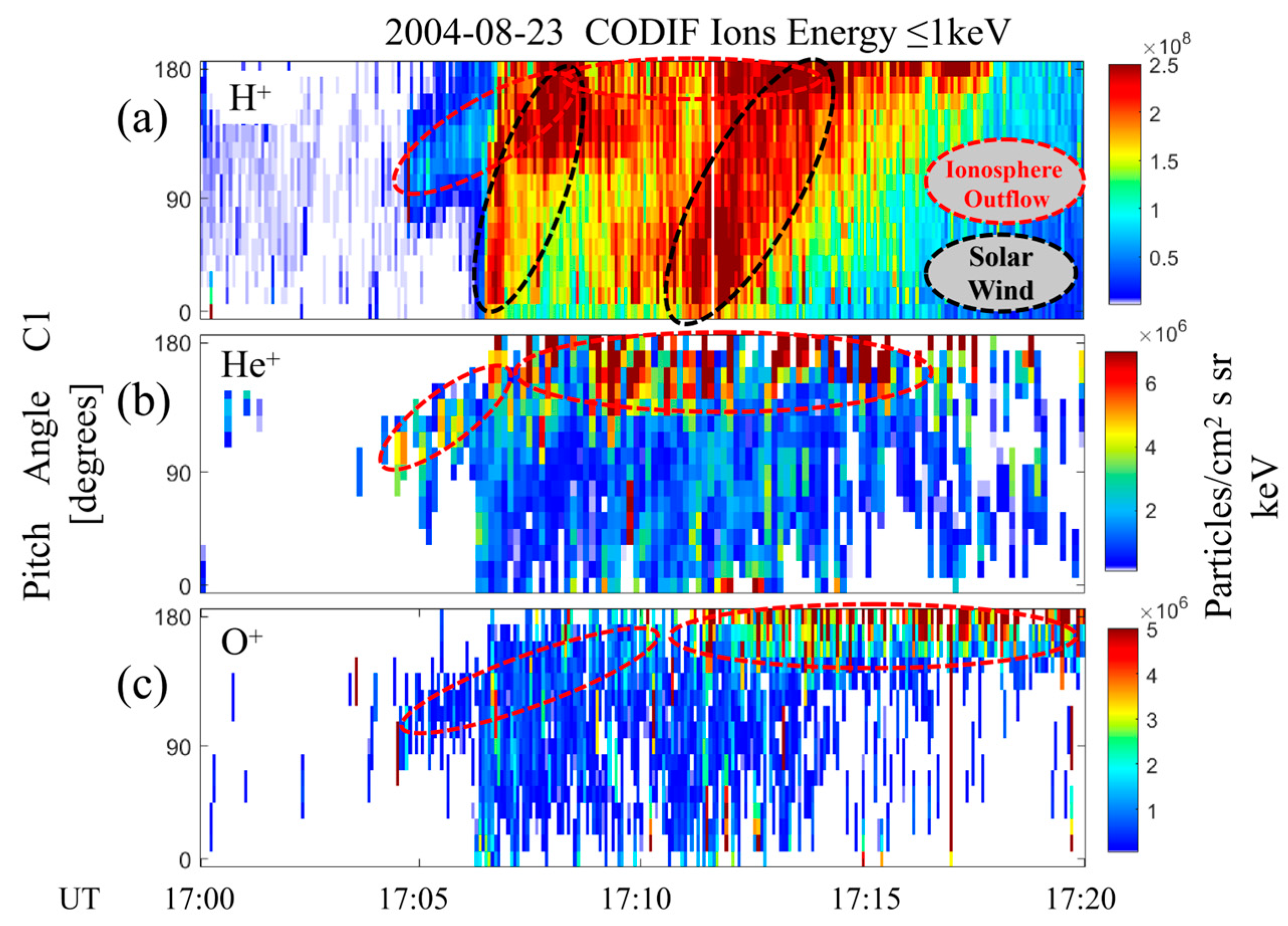
To determine the composition of the cusp cold ions (energy ≤ 1 keV), pitch angle distributions of H+, He+ and O+ are shown in Figure 4. In this event, H+ density was about two orders of magnitude higher than He+ and O+. In Figure 4a, two groups of H+ turning flow can be identified between 17:07 and 17:11 UT and between 17:11 and 17:18 UT. The first group of H+ (17:07 to 17:11 UT) was mainly from solar wind particle precipitation and return. The second group of enhanced H+ (17:11 to 17:18 UT) precipitation might be caused by the crossing of a double cusp or the motion of the cusp [34,40]. The precipitation flux of H+ was essentially stable in a narrow channel in the cusp. The outflowing ions, however, extended into a much wider area. A tentative explanation for the difference may be that the gravity force decelerated the reflected ions, which allowed them to stay longer on the anti-sunward-moving magnetic field line in the cusp and arrive at higher latitude regions [41].
For He+ and O+ ions, outflow particles (close to 180° pitch angle) were the most obvious in the pitch distribution. High fluxes of heavier ion O+ were observed at higher latitudes compared with He+ outflow. This is because He+ is lighter than O+ ions and less affected by the gravity force, so it can be lifted along the field line faster than O+. According to Figure 4a, H+ also showed remarkable outflow from the ionosphere, but it is mixed with solar wind–reflecting ions and is difficult to distinguish. It is also worth noting that some He+ and O+ ions flow downward in the H+ downward flux channel. Stenuit and Sauvaud [42] and Lee et al. [43] found that cold ions can join the dayside reconnection process at the magnetopause, and then these cold ions may flow downward from the dayside reconnection site. Another possible source of the He+ and O+ signal that co-occurs with solar wind H+ is the “spillover” effect of high H+ flux in the cusp, since these groups of He+ and O+ were in the same energy range with solar wind H+ [44].

2.4. Potential Drop and Poynting Flux in Cold Ion Out Flow Region

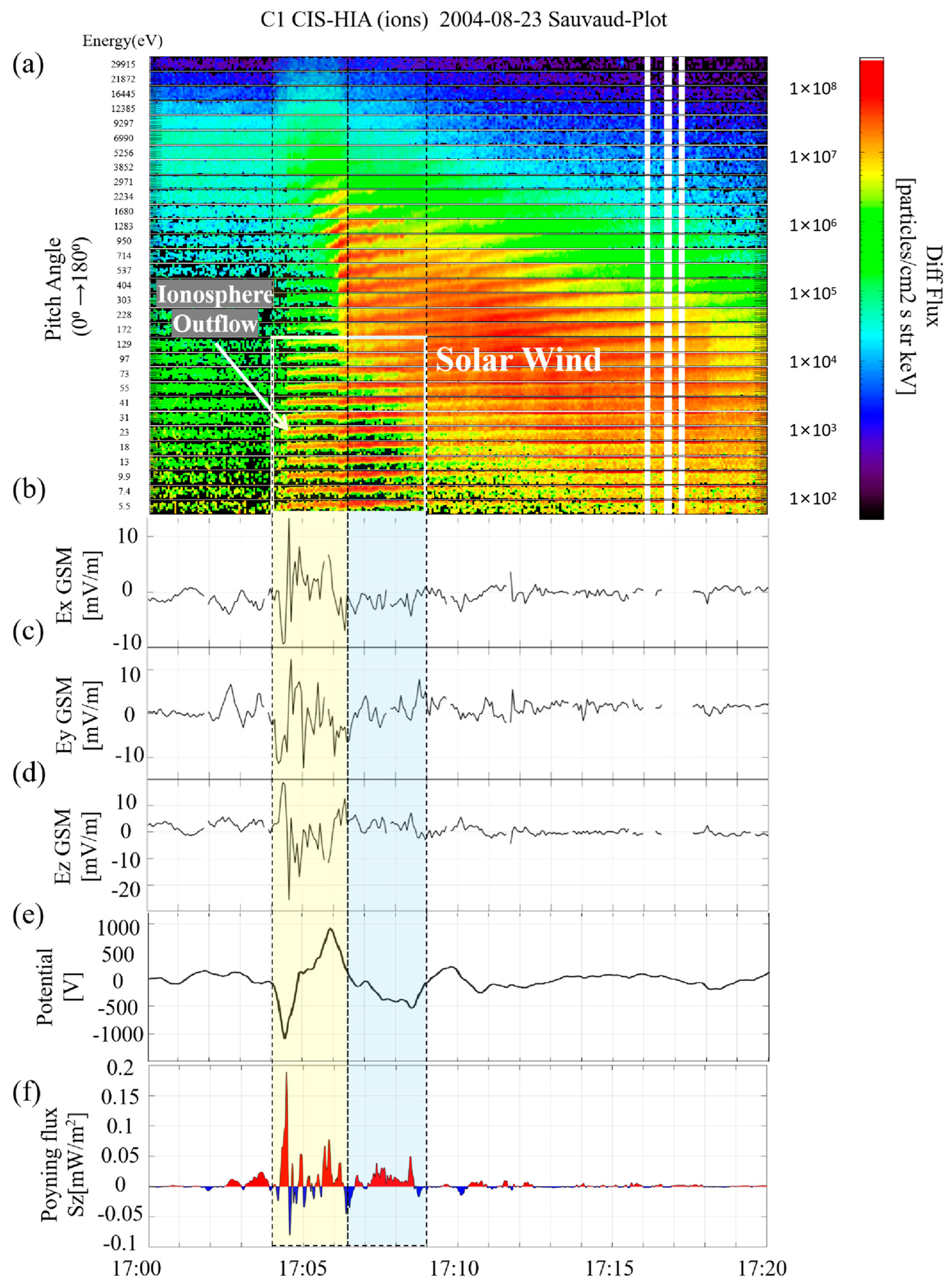
To show the cusp ion dynamics in detail, the Sauvaud plot of CIS-HIA was included in this study. The Sauvaud plot provides full pitch angle information for all the energy channels within one figure and can help us to get more details about the ion flux variation of the cusp in this study. In Figure 5a, ion differential flux showed oblique distribution with time in higher energy channels (above 100 eV). The slope of the skewed distribution increases with energy, which means the pitch angle change of high-energy ions was faster than that of low-energy ions. In other words, high-energy ions would return from low altitude to a higher altitude in a short time or distance, and lower energy ions’ return flux could extend to a much larger area. For the cold ion group in the cusp/low latitude boundary, ions first appeared as a conics distribution (pitch angle between 90° and 140°) between 17:04 and 17:07 UT. Later, when cold ions extended to the ion precipitation channel, after 17:07 UT, ions conics turned gradually to 180° pitch angle upward flow. In the low-energy panels (between 5.5 eV and 41 eV), some ions outflow was identified in the high-latitude region (red parts on the top side of each energy channel, between 17:10 and 17:20 UT). Based on the particle composition analysis in Figure 4, these signals are from ionospheric outflowing ions and had a different origin from the reflected ions.
The electric fields measured by Cluster EFW are shown in Figure 5b–d. The directions of the measurement have converted to the GSM (geocentric solar magnetospheric coordinates) coordinate system. Among electric field panels, strong components can be observed at both low- and high-latitude boundaries of the LLBL (yellow box region) in all three directions. By projecting the electric field vectors onto the spacecraft orbit, and integrating the orbit-aligned electric field components over the distance, the electric potential difference along the spacecraft orbit can be obtained. The results are shown in Figure 5e; 4 s resolution EFW data were used in this calculation. A local potential difference of about −1000 V can be found at the ions conics low-altitude boundary. After that, the potential raised to about 2000 V at the boundary of the solar wind down-flowing ions channel. After passing the local peak at about 17:06 UT, the potential quickly drops down to −300 V in the ions conics extending area. Such different electric field environments may provide some clues to explain the different characteristics of the outflow ions.
Figure 5f shows the ambient magnetic field–aligned Poynting energy flux over the spacecraft orbit. The Poynting vector Sz is defined as
Sz = E × δ B μ 0 B ^ 0
where E is the perturbation electric field obtained by Cluster EFW, B0 is the ambient magnetic field obtained by Cluster FGM, δB is the perturbation magnetic field calculated by B0 minus a 5 min smoothed B0 as background magnetic field, and μ0 is the vacuum permeability [12,19,45].
In the yellow box region, both up and downward Poynting flux can be observed. However, on the boundary of the yellow region, downward Poynting flux is dominant. In the middle, the Poynting flux is balanced in two directions. A clear upward Poynting flux can be observed between the yellow and green regions, which can also be regarded as the boundary between LLBL and the cusp. After that, within the light green box region, a purely downward Poynting flux is dominating, where we can also see the cold ions flowing upward intensively and solar wind ions flowing downward in the opened field line cusp region. The correlation between Poynting flux and the ionospheric ions outflow means ions below this region could be heated by the energy input, which was supported by the upflowing of cold ions in the same region. In addition, Poynting fluxes in these regions are highly structured, suggesting that two highlighted regions (yellow and green) in this study may be controlled by some different mechanisms. The stronger cold ion outflow in the cusp (green region) may benefit from additional acceleration in the same region. To investigate how much nonadiabatic acceleration works in this region, the ion energy distribution of H+ and O+ was studied in Section 2.5.

2.5. LLBL/Cusp Ions Energy Distribution

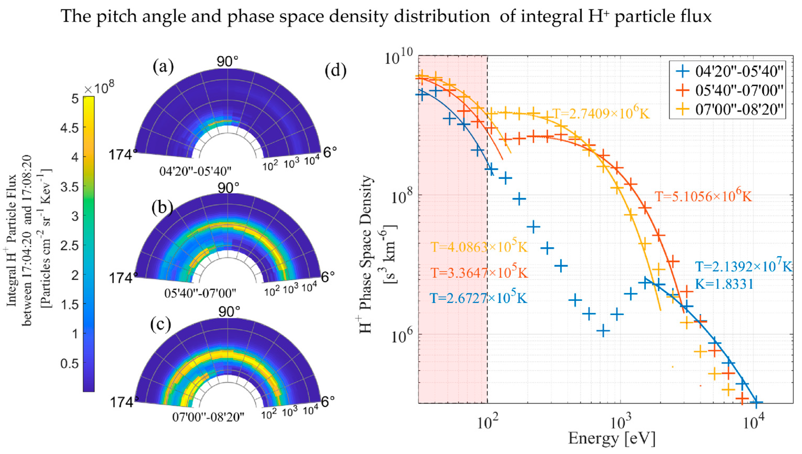
Two groups of H+ particles of different energies can be found from the pitch angle distributions. In Figure 6a, the low-energy H+ presented a conics distribution with pitch angle between 90 and 120°, and almost no downward H+ can be found in this region, which means Cluster C1 was just across the open–closed field line boundary. In Figure 6b, downward keV H+ shows up. Meanwhile, the pitch angle of low-energy H+ turned to 120–160°. In Figure 6c, the pitch angle of low-energy H+ turned to 160–180°, and the high-energy H+ extended to all pitch angles. Note, however, that energy was slightly lower than before. The particle phase space density (PSD) distribution as a function of energy is shown in Figure 6d. The H+ spectra with energy <3 keV was fitted by a Maxwellian distribution, and the fitting temperature of each region was markedwith corresponding colors in the figure. For the cold H+ ions (<100 eV), the temperature had a slight increase from 2.6727 × 10⁵ K to 4.0863 × 10⁵ K, which presented a local heating. For the downward H+ (above 100 eV), the temperature decreased from 5.1056 × 10⁶ K to 2.7409 × 10⁶ K, which agrees with the precipitated particle energy dispersion in the cusp in Figure 5. The particle over 3 keV was fitted by a Kappa distribution, and the result shows a temperature of 2.1392 × 10⁷ K with K = 1.8331, indicating these particles are from background particle distribution and have almost no change in the whole area.
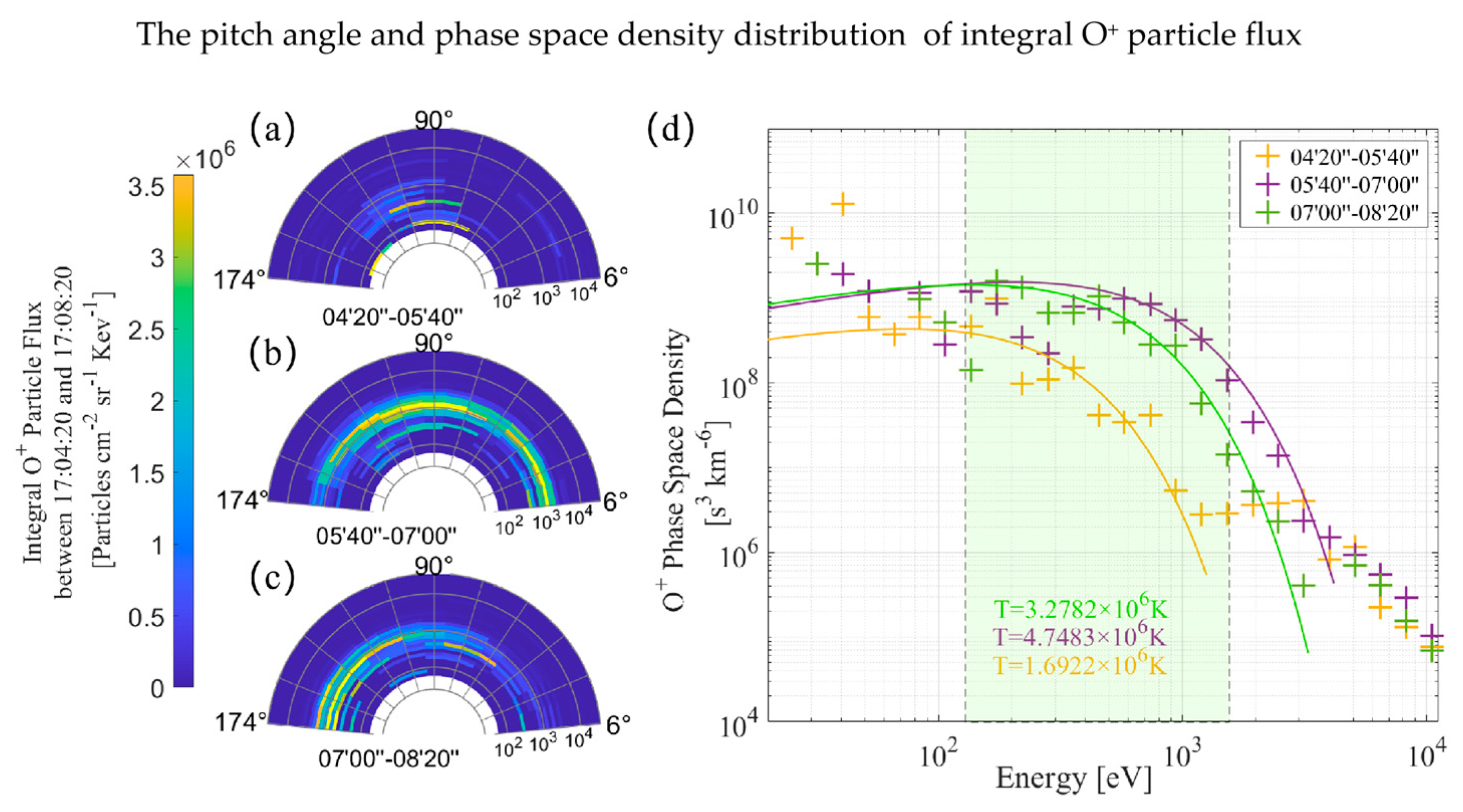
For the same time interval, the O+ pitch angle and PSD distribution are shown in Figure 7. Some keV O+ can be observed in Figure 7b,c. As mentioned in Section 2.3, it is difficult to confirm whether the keV O+ was from solar wind precipitation or the “spillover” effect of high H+ flux. However, compared with H+ solar wind flux in Figure 6, keV O+ in Figure 7b,c had quite a different pitch angle distribution, which indicates that these keV O+ were not, or not all, caused by the “spillover” effect of high H+ flux. For example, in Figure 6b, keV H+ flux had a flux maximum at pitch angle around 20° and a quasilinear reduction with a pitch angle increasing. In contrast, in Figure 7b, two independent flux maximums can be observed at pitch angle 120° and 20°, which indicate that the 120° maximum is not related to the solar wind H+ flux “spillover” but from the cold ionospheric O+ heating at LLBL/cusp.
Specifically, the O+ was accelerated to an energy range between 160 and 1600 eV, which is about 16 times higher than the energy of the cold H+ group. This means O+ and H+ were accelerated to a common speed in the ions conics region of the LLBL/cusp. However, within the pitch angle turning process, the temperature of the O+ rose from 1.6922 × 10⁶ K up to 4.7483 × 10⁶ K, as shown in Figure 7d; H+ heated in the same region. The temperature rising of the particles presents a nonadiabatic acceleration process, since adiabatic acceleration (with the particle’s magnetic moment µ conserved) only shifts the whole spectrum to the right side but leaves the temperature unchanged, while the nonadiabatic acceleration will cause a rise in the temperature, similar work can be referred form Liu et al. [46], Daglis et al. [47] and Ono et al. [48]. So, it is reasonable to believe in Figure 7a–c, where O+ ions presented a pitch angle turning in the same region of the cusp.

3. Discussion

The source of free energy that powers the outflow is a combination of solar UV radiation and solar wind electromagnetic energy. Earlier studies [49,50,51,52] revealed a good correlation between the total outflow rate and measurements of the solar and geomagnetic activity by the DE-1, Polar, and Akebono satellites’ long-term average ion outflow data. In the cusp region, the ion outflow observed at high altitudes is the result of a long chain of processes. The most dominant mechanism in this process is transverse heating associated with enhancements in the broadband extremely low frequency (BBELF) wave activity [53].
In this study, a more detailed ion outflow process is revealed. During southward IMF, the Poynting flux and upflowing cold ions sharing the same channel in the cusp boundary region indicate that the ionospheric cold ions are heated by wave activity. Further more, cold ion pitch angle distributions demonstrate cold ions with pitch angle in conics distribution flowing upward at the LLBL/cusp. When these ionospheric upflowing ions extended to the solar wind ion precipitation channel, the pitch angle of these cold ions turned to 180° from conic distribution and mixed up with reflected solar wind ions. By analyzing the Polar spacecraft data, Topliss et al. [54] suggested that the ions conics pitch angle turning is to maintain charge neutrality at the equatorial edge of the cusp. With the aid of higher resolution Cluster CIS data, Bogdanova at al. [55] found that electron edge has been observed in 87% of the mid-altitude cusp crossings by Cluster, and the size of the boundary layer varies between 0° and 2° ILAT. Lindstedt et al. [16] presented observations of oxygen energization by strong localized electric fields at the boundary between the cusp and the lobe. The electric fields represent a spatial structure with a transverse size of ~100 km. Such electric fields can be related to a reconnection separatrix region. Oxygen ions are non-adiabatic in the strong electric field region and can be accelerated by the electric field to gain energy of several keV. Additional heating can be provided by waves at the oxygen cyclotron frequency. Their observations demonstrate that perpendicular electric fields in localized structures are one of the mechanisms providing keV O+ ions in the magnetosphere. In this event, a potential peak (Figure 5e) at the solar wind ion precipitation channel boundary showed the existence of a strong local electric field along the C1 orbit, which is in agreement with the conclusions of Lindstedt [16]. In the meanwhile, PSD distribution results suggested that the temperature rising of the particles showed that a non-adiabatic acceleration happened in the same region. In the high-latitude cusp region, solar wind particles are reflected upward. However, Poynting energy flux and field-aligned electric potential drop are rare in this region, which suggests that particles are mainly controlled by the magnetic mirror force in the cusp region.

4. Conclusions

In this paper, with the observations from Cluster spacecraft, particles dynamic processes in the Earth’s cusp region are carefully explored, including cusp ions energy dispersion, outflowing cold ions, Poynting flux in LLBL/cusp, and outflowing plasma temperature. Outflowing particles with different origins were determined via the Sauvaud plot. One group of outflowing ions consists of the reflected solar wind ions from the magnetic mirror point in the cusp ionosphere. The other group of outflowing ions is attributed to the heated ionospheric ions, which can be distinguished from pitch angle distributions.
The main results are as follows:
  • Cusp ion outflow is composed of the reflected solar wind ions and the ionospheric outflow ions. The ionospheric outflow was energized by the Poynting flux, and the Poynting flux is purely downward in the cusp but bi-directional in LLBL.
  • Cold ion groups on the LLBL/cusp were mainly composed of H+ and O+, and all the cold ion flows were turning upward gradually when they drifted to the higher latitude side of the cusp, which may caused by the potential drop in the LLBL/cusp.
  • The cold ion outflow in the LLBL/cusp may benefit from additional nonadiabatic acceleration in the same region.
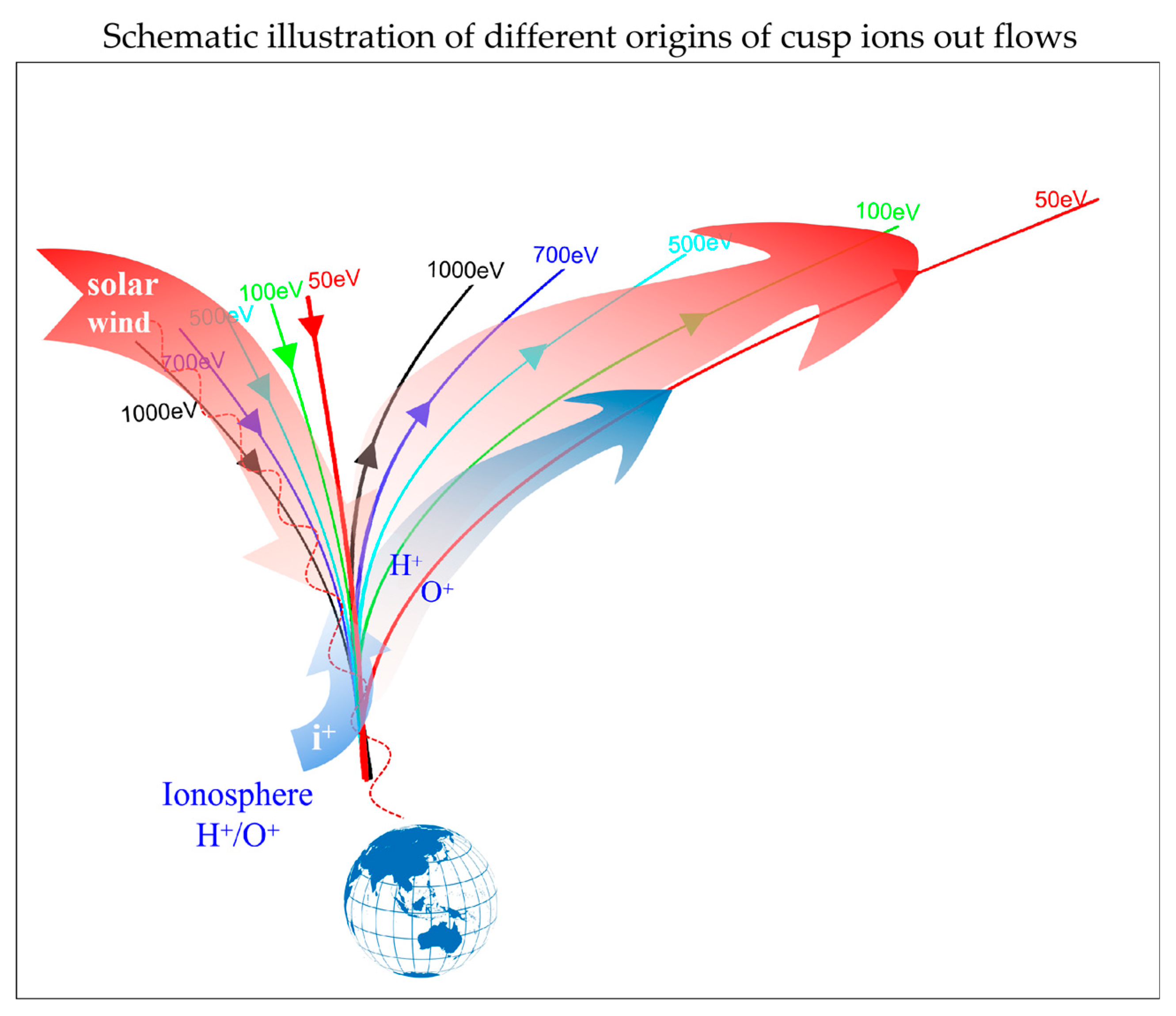
A schematic illustration is given in Figure 8 to summarize the two different origins of cusp ions outflows associated with the magnetopause reconnection. Solar wind ions travel along magnetic field lines in the LLBL/cusp region. After these particles reach the magnetic mirror point in the ionosphere, parts of precipitated ions are reflected back to the magnetosphere if they are not dissipated in the ionosphere. As shown from the C1 CIS data, both downward and upward ion fluxes can be observed in the same region. The arrow lines with different colors in Figure 8 show solar wind ions trajectories in the cusp. Cold ions from the ionosphere flow upward in the LLBL/cusp region when their flow enters the down-flowing H+ channel. Ionospheric H+ and O+ ions were accelerated to a common velocity in the LLBL/cusp and then flew out via mass-related trajectories. The perpendicular electric fields in the LLBL/cusp play an important role in the ionospheric outflow particle energization. Overall, this study provides a picture of fine-structured ions outflow in the Earth’s LLBL/cusp region.

Author Contributions

Conceptualization, B.L. and H.Y.; methodology, B.L., H.Y., J.S., C.Y., C.P.E. and Q.Z.; software, B.L., Y.W. and J.R.; formal analysis, B.L., J.S., Z.H., J.L. and X.C.; investigation, H.Y.; resources, H.Y.; data curation, Y.W., J.R., C.Y., C.P.E. and Q.W.; writing—original draft preparation, B.L.; writing—review and editing, B.L.,C.Y. and H.Y.; visualization, B.L.; supervision, Q.Z.; project administration, H.Y.; funding acquisition, H.Y. All authors have read and agreed to the published version of the manuscript.

Funding

This research was funded by research grant of Natural Science Foundation of China Grant Numbers: 41831072, 42074199, 41874195, 42120104003, 42130210, and 41874173, National Key Research and Development Program of China (grant numbers 2021YFE0106400, 2018YFC1407303), Space Science Pilot Project of the Chinese Academy of Sciences (grant number XDA15350202), International Cooperation Advance Research on Key Scientific Issues of the International Meridian Project (A131901W14), Shanghai Science and Technology Innovation Action Plan (No. 21DZ1206100), Shanghai Pujiang Program (21PJD078), and Shanxi International Science and Technology Cooperation Program (2021kw-06).

Institutional Review Board Statement

Not applicable.

Informed Consent Statement

Not applicable.

Data Availability Statement

The data for this paper are available at the Cluster Active Archive (https://www.cosmos.esa.int/web/csa, accessed on 16 January 2023) and (https://omniweb.gsfc.nasa.gov/form/omni_min.html, accessed on 16 January 2023). The OVT3.0 can be found from web https://ovt.irfu.se, accessed on 16 January 2023. IRFU-matlab are available at https://github.com/irfu/irfu-matlab, accessed on 16 January 2023.

Acknowledgments

We are delighted to acknowledge the Cluster mission. The Cluster project was supported by the European Space Agency. The Development of Orbit Visualization Tool and irfu-matlab package are supported by the Swedish Institute of Space Physics (IRF-U), the ESA/ESTEC Cluster and Cluster Active Archive projects, and the Svenska Institutet (SI). The Orbit Visualization Tool uses some algorithms developed by T.S. Kelso, N. Tsyganenko, D. Weimer and J.-H. Shue.

Conflicts of Interest

The authors declare no conflict of interest.

References

  1. Milan, S.E.; Lester, M.; Cowley, S.W.H.; Oksavik, K.; Brittnacher, M.; Greenwald, R.A.; Sofko, G.; Villain, J.-P. Variations in the polar cap area during two substorm cycles. Ann. Geophys. 2003, 21, 1121–1140. [Google Scholar] [CrossRef] [Green Version]
  2. Lu, J.Y.; Zhang, H.X.; Wang, M.; Gu, C.L.; Guan, H.Y. Magnetosphere response to the IMF turning from north to south. Earth Planet. Phys. 2019, 3, 8–16. [Google Scholar] [CrossRef]
  3. Haerendel, G.; Paschmann, G. Entry of solar wind plasma into the magnetosphere. In Physics of the Hot Plasma in the Magnetosphere; Hultqvist, B., Stenflo, L., Eds.; Springer: Boston, MA, USA, 1975. [Google Scholar] [CrossRef]
  4. Hill, T.W.; Reiff, P.H. Evidence of magnetospheric cusp proton acceleration by magnetic merging at the dayside magnetopause. J. Geophys. Res. 1977, 82, 3623–3628. [Google Scholar] [CrossRef]
  5. Axford, W.I. The polar wind and the terrestrial helium budget. J. Geophys. Res. 1968, 73, 6855–6859. [Google Scholar] [CrossRef]
  6. Nishida, A. Formation of plasmapause, or magnetospheric plasma knee, by the combined action of magnetospheric convection and plasma escape from the tail. J. Geophys. Res. 1966, 71, 5669–5679. [Google Scholar] [CrossRef]
  7. Ganguli, S.B.; Mitchell, H.G.; Palmadesso, P.J. Behavior of ionized plasma in the high latitude topside ionosphere-the polar wind. Planet. Space Sci. 1987, 35, 703–714. [Google Scholar] [CrossRef]
  8. Sheeley, N.R. Polar faculae during the interval 1906–1975. J. Geophys. Res. 1976, 81, 3462–3464. [Google Scholar] [CrossRef]
  9. Sharp, R.D.; Johnson, R.G.; Shelley, E.G. Observation of an ionospheric acceleration mechanism producing energetic (keV) ions primarily normal to the geomagnetic field direction. J. Geophys. Res. 1977, 82, 3324–3328. [Google Scholar] [CrossRef]
  10. Gorney, D.J.; Clarke, A.; Croley, D.; Fennell, J.; Luhmann, J.; Mizera, P. The distribution of ion beams and conics below 8000 km. J. Geophys. Res. 1981, 86, 83–89. [Google Scholar] [CrossRef]
  11. Yau, A.; André, M. Sources of ion outflow in the high latitude ionosphere. Space Sci. Rev. 1997, 80, 1–25. [Google Scholar] [CrossRef]
  12. Bouhram, M.; Dubouloz, N.; Malingre, M.; Jasperse, J.R.; Pottelette, R.; Senior, C.; Delcourt, D.; Carlson, C.W.; Roth, I.; Berthomier, M.; et al. Ion outflow and associated perpendicular heating in the cusp observed by Interball Auroral Probe and Fast Auroral Snapshot. J. Geophys. Res. 2002, 107, SMP 4-1–SMP 4-13. [Google Scholar] [CrossRef] [Green Version]
  13. Bouhram, M.; Malingre, M.; Jasperse, J.R.; Dubouloz, N. Modeling transverse heating and outflow of ionospheric ions from the dayside cusp/cleft. 1 A parametric study. Ann. Geophys. 2003, 21, 1753–1771. [Google Scholar] [CrossRef] [Green Version]
  14. Bouhram, M.; Malingre, M.; Jasperse, J.R.; Dubouloz, N.; Sauvaud, J.-A. Modeling transverse heating and outflow of ionospheric ions from the dayside cusp/cleft. 2 Applications. Ann. Geophys. 2003, 21, 1773–1791. [Google Scholar] [CrossRef] [Green Version]
  15. Bouhram, M.; Klecker, B.; Miyake, W.; Rème, H.; Sauvaud, J.-A.; Malingre, M.; Kistler, L.; Blăgău, A. On the altitude dependence of transversely heated O+ distributions in the cusp/cleft. Ann. Geophys. 2004, 22, 1787–1798. [Google Scholar] [CrossRef] [Green Version]
  16. Lindstedt, T.; Khotyaintsev, Y.V.; Vaivads, A.; André, M.; Nilsson, H.; Waara, M. Oxygen energization by localized perpendicular electric fields at the cusp boundary. Geophys. Res. Lett. 2010, 37, L09103. [Google Scholar] [CrossRef]
  17. Nilsson, H.; Barghouthi, I.A.; Slapak, R.; Eriksson, A.I.; André, M. Hot and cold ion outflow: Spatial distribution of ion heating. J. Geophys. Res. 2012, 117, A11201. [Google Scholar] [CrossRef] [Green Version]
  18. Liao, J.; Kistler, L.M.; Mouikis, C.G.; Klecker, B.; Dandouras, I. Acceleration of O+ from the cusp to the plasma sheet. J. Geophys. Res. 2015, 120, 1022–1034. [Google Scholar] [CrossRef]
  19. Li, B.; Marklund, G.; Karlsson, T.; Sadeghi, S.; Lindqvist, P.A.; Vaivads, A.; Fazakerley, A.; Zhang, Y.; Lucek, E.; Sergienko, T.; et al. Inverted-V and low-energy broadband electron acceleration features of multiple auroras within a large-scale surge. J. Geophys. Res. Space Phys. 2013, 118, 5543–5552. [Google Scholar] [CrossRef]
  20. Marklund, G.T.; Ivchenko, N.; Karlsson, T.; Fazakerley, A.; Dunlop, M.; Lindqvist, P.A.; Buchert, S.; Owen, C.; Taylor, M.; Vaivalds, A.; et al. Temporal evolution of the electric field accelerating electrons away from the auroral ionosphere. Nature 2001, 414, 724–727. [Google Scholar] [CrossRef]
  21. Marklund, G.; Lindqvist, P.-A. Cluster multi-probing of the aurora during two decades. J. Geophys. Res. Space Phys. 2021, 126, e2021JA029497. [Google Scholar] [CrossRef]
  22. Norqvist, P.; André, M.; Tyrland, M. A statistical study of ion energization mechanisms in the auroral region. J. Geophys. Res. 1998, 103, 23459–23473. [Google Scholar] [CrossRef]
  23. André, M.; Norqvist, P.; Andersson, L.; Eliasson, L.; Eriksson, A.I.; Blomberg, L.; Erlandson, R.E.; Waldemark, J. Ion energization mechanisms at 1700 km in the auroral region. J. Geophys. Res. 1998, 103, 4199–4222. [Google Scholar] [CrossRef]
  24. Sun, J.; Wang, G.; Zhang, T.; Hu, H.; Yang, H. Evidence of Alfvén waves generated by mode coupling in the magnetotail lobe. Geophys. Res. Lett. 2022, 49, e2021GL096359. [Google Scholar] [CrossRef]
  25. André, M.; Crew, G.B.; Peterson, W.K.; Persoon, A.M.; Pollock, C.J.; Engebretson, M.J. Ion heating by broadband low-frequency waves in the cusp/cleft. J. Geophys. Res. 1990, 95, 20809–20823. [Google Scholar] [CrossRef]
  26. Jacobsen, K.S.; Moen, J.I. On the correlation between Broad-Band ELF wave power and ion fluxes in the cusp. Ann. Geophys. 2010, 28, 1249–1261. [Google Scholar] [CrossRef] [Green Version]
  27. Slapak, R.; Nilsson, H.; Waara, M.; André, M.; Stenberg, G.; Barghouthi, I.A. O+ heating associated with strong wave activity in the high altitude cusp and mantle. Ann. Geophys. 2011, 29, 931–944. [Google Scholar] [CrossRef] [Green Version]
  28. Waara, M.; Nilsson, H.; Slapak, R.; Andre, M.; Stenberg, G. Oxygen ion energization by waves in the high altitude cusp and mantle. Ann. Geophys. 2012, 30, 1309–1314. [Google Scholar] [CrossRef] [Green Version]
  29. Pitout, F.; Bogdanova, Y.V. The polar cusp seen by Cluster. J. Geophys. Res. Space Phys. 2021, 126, e2021JA029582. [Google Scholar] [CrossRef]
  30. Dandouras, I. Ion outflow and escape in the terrestrial magnetosphere: Cluster advances. J. Geophys. Res. Space Phys. 2021, 126, e2021JA029753. [Google Scholar] [CrossRef]
  31. Newell, P.T.; Meng, C.I. Mapping the dayside ionosphere to the magnetosphere according to particle precipitation characteristics. Geophys. Res. Lett. 1992, 19, 609–612. [Google Scholar] [CrossRef]
  32. Smith, M.F.; Lockwood, M. Earth’s magnetospheric cusps. Rev. Geophys. 1996, 34, 233–260. [Google Scholar] [CrossRef]
  33. Lockwood, M. Relationship of dayside auroral precipitations to the open-closed separatrix and the pattern of convective flow. J. Geophys. Res. 1997, 102, 17475–17487. [Google Scholar] [CrossRef]
  34. Escoubet, C.P.; Berchem, J.; Trattner, K.J.; Pitout, F.; Richard, R.; Taylor, M.G.G.T.; Soucek, J.; Grison, B.; Laakso, H.; Masson, A.; et al. Double cusp encounter by Cluster: Double cusp or motion of the cusp? Ann. Geophys. 2013, 31, 713–723. [Google Scholar] [CrossRef] [Green Version]
  35. Gustafsson, G.; Boström, R.; Holback, B.; Holmgren, G.; Lundgren, A.; Stasiewicz, K.; Åhlén, L.; Mozer, F.S.; Pankow, D.; Harvey, P.; et al. The electric field and wave experiment for the Cluster mission. Space Sci. Rev. 1997, 79, 137–156. [Google Scholar] [CrossRef]
  36. Balogh, A.; Dunlop, M.W.; Cowley, S.W.H.; Southwood, D.J.; Thomlinson, J.G.; Glassmeier, K.H.; Musmann, G.; Lühr, H.; Buchert, S.; Acuna, M.H.; et al. The Cluster magnetic investigation. Space Sci. Rev. 1997, 79, 65–91. [Google Scholar] [CrossRef]
  37. Fuselier, S.A.; Lockwood, M.; Onsager, T.G.; Peterson, W.K. The source population for the cusp and cleft/LLBL for southward IMF. Geophys. Res. Lett. 1999, 26, 1665–1669. [Google Scholar] [CrossRef] [Green Version]
  38. Bogdanova, Y.V.; Owen, C.J.; Fazakerley, A.N.; Klecker, B.; Rème, H. Statistical study of the location and size of the electron edge of the Low-Latitude Boundary Layer as observed by Cluster at mid-altitudes. Ann. Geophys. 2006, 24, 2645–2665. [Google Scholar] [CrossRef] [Green Version]
  39. Escoubet, C.P.; Bosqued, J.M. The influence of IMF-Bz and/or AE on the polar cusp: An overview of observations from the Aureol-3 satellite. Planet. Space Sci. 1989, 37, 609–626. [Google Scholar] [CrossRef]
  40. Wing, S.; Newell, P.T.; Ruohoniemi, J.M. Double cusp: Model prediction and observational verification. J. Geophys. Res. 2001, 106, 25571–25593. [Google Scholar] [CrossRef]
  41. Kronberg, E.A.; Ashour-Abdalla, M.; Dandouras, I. Circulation of Heavy Ions and Their Dynamical Effects in the Magnetosphere: Recent Observations and Models. Space Sci. Rev. 2014, 184, 173–235. [Google Scholar] [CrossRef]
  42. Stenuit, H.; Sauvaud, J.-A. Evidence for storm-time ionospheric ion precipitation in the cusp with magnetosheath energy. Ann. Geophys. 2004, 22, 1765–1771. [Google Scholar] [CrossRef] [Green Version]
  43. Lee, S.H.; Zhang, H.; Zong, Q.-G.; Otto, A.; Sibeck, D.G.; Wang, Y.; Glassmeier, K.-H.; Daly, P.W.; Rème, H. Plasma and energetic particle behaviors during asymmetric magnetic reconnection at the magnetopause. J. Geophys. Res. Space Phys. 2014, 119, 1658–1672. [Google Scholar] [CrossRef] [Green Version]
  44. Dandouras, I.; Barthe, A.; the CIS Team. User Guide to the CIS measurements in the Cluster Active Archive (CAA). 2014. Available online: https://caa.esac.esa.int/documents/UG/CAA_EST_UG_CIS_v37.pdf (accessed on 16 January 2023).
  45. Griffiths, D. Introduction to Electrodynamics, 4th ed.; P347; Cambridge University Press: Cambridge, UK, 2017; ISBN 9781108420419. [Google Scholar] [CrossRef]
  46. Liu, W.W.; Rostoker, G. Energetic ring current particles generated by recurring substorm cycles. J. Geophys. Res. Space Phys. 1995, 100, 21897–21910. [Google Scholar] [CrossRef]
  47. Daglis, I.A.; Thorne, R.M.; Baumjohann, W.; Orsini, S. The terrestrial ring current: Origin, formation, and decay. Rev. Geophys. 1999, 37, 407–438. [Google Scholar] [CrossRef]
  48. Ono, Y.; Nosé, M.; Christon, S.P.; Lui, A.T.Y. The role of magnetic field fluctuations in nonadiabatic acceleration of ions during dipolarization. J. Geophys. Res. Space Phys. 2009, 114, 1–11. [Google Scholar] [CrossRef]
  49. Yau, A.W.; Shelley, E.G.; Peterson, W.K.; Lenchyshyn, L. Energetic auroral and polar ion outflow at DE-1 altitudes: Magnitude, composition, magnetic activity dependence and long term variations. J. Geophys. Res. 1985, 90, 8417–8432. [Google Scholar] [CrossRef]
  50. Yau, A.W.; Peterson, W.K.; Shelley, E.G. Quantitative parametrization of energetic ionospheric ion outflow. Geophys. Monogr. Ser. 1988, 44, 211–217. [Google Scholar] [CrossRef]
  51. Peterson, W.K.; Collin, H.L.; Yau, A.W.; Lennartsson, O.W. Polar/Toroidal Imaging Mass-Angle Spectrograph observations of suprathermal ion outflow during solar minimum conditions. J. Geophys. Res. 2001, 106, 6059–6066. [Google Scholar] [CrossRef]
  52. Cully, C.M.; Donovan, E.F.; Yau, A.W.; Arkos, G.G. Akebono/Suprathermal Mass Spectrometer observations of low-energy ion outflow: Dependence on magnetic activity and solar wind conditions. J. Geophys. Res. 2003, 108, 1093–1103. [Google Scholar] [CrossRef] [Green Version]
  53. Lund, E.J.; Mobius, E.; Carlson, C.W.; Ergun, R.E.; Kistler, L.M.; Klecker, B.; Klumpar, D.M.; McFadden, J.P.; Popecki, M.A.; Strangeway, R.J.; et al. Transverse ion acceleration mechanism in the aurora at solar minimum: Occurrence distributions. J. Atmos. Terr. Phys. 2000, 62, 467–475. [Google Scholar] [CrossRef]
  54. Topliss, S.; Johnstone, A.; Coates, A.; Peterson, W.K.; Kletzing, C.A.; Russell, C.T. Charge neutrality and ion conic distributions at the equatorward electron edge of the midaltitude cusp. J. Geophys. Res. 2001, 106, 21095–21108. [Google Scholar] [CrossRef]
  55. Bogdanova, Y.V.; Owen, C.J.; Fazakerley, A.N.; Klecker, B.; Reme, H. Cluster Observations of the Electron Low-Latitude Boundary Layer at Mid-Altitudes. In Proceedings of the Cluster and Double Star Symposium—5th Anniversary of Cluster in Space, Noordwijk, The Netherlands, 19–23 September 2005. [Google Scholar]
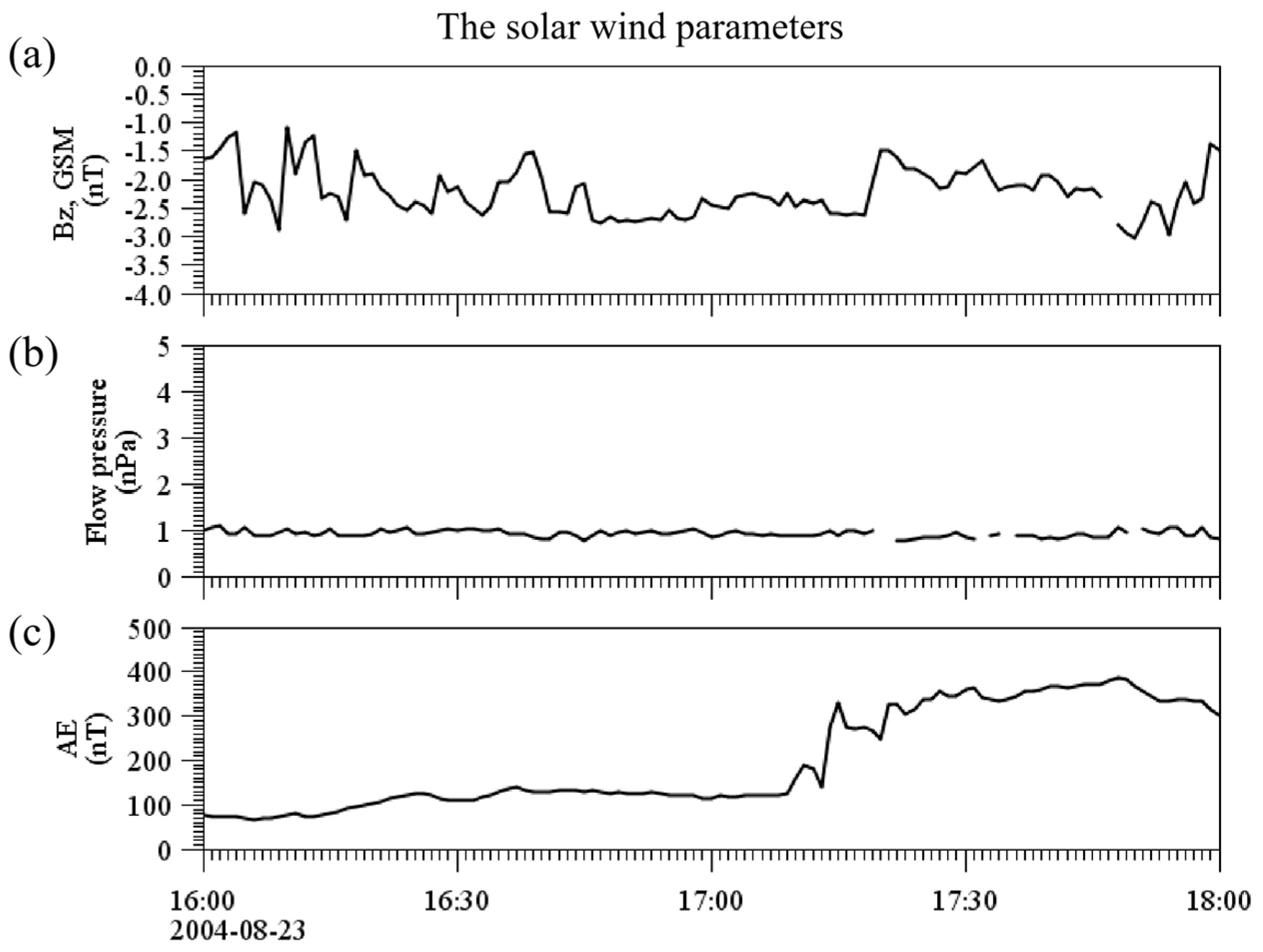
Figure 1. The solar wind parameters observed on 23 August 2004. (a) OMNI 1 min IMF Bz. (b) Solar wind flow pressure. (c) AE index between 16:00 and 18:00 UT, 23 August 2004.
Magnetochemistry 09 00039 g001
Figure 2. Cluster orbit on 23 August 2004. (a) Cluster orbit compared with Tsyganenko 96 model in GSM coordinate X–Z plane. (b) Same orbit in Y–Z plane. The plot obtained by Orbit Visualization Tool (OVT) 3.0.
Magnetochemistry 09 00039 g002
Figure 3. Cluster C1 particle differential energy flux and background magnetic field. (a) Down-going ion flux observed by Cluster C1 CIS HIA at pitch angle 5°; the region of cusp is highlighted by the double arrow between 17:05 and 17:20. (b) Perpendicular ion flux at pitch angle 95°. (c) Up-flowing ion flux at pitch angle 174°. (d) Down-going electron flux at pitch angle 5°. (e) Perpendicular electron flux at pitch angle 95°. (f) Up-going electron flux at pitch angle 174°. (g) Total magnetic field observed by FGM. Yellow box regions represent the LLBL, and green box regions represent cold ions upward flux. UT, MLT, iLat, and RE information are listed on the bottom.
Magnetochemistry 09 00039 g003
Figure 4. Pitch angle distribution of H+, He+, and O+(energy ≤ 1 keV) obtained from Cluster C1 CODIF shown in (ac). Ionosphere outflow is highlighted by red ovals and solar wind particles are highlighted by black ovals.
Magnetochemistry 09 00039 g004
Figure 5. (a) CIS−HIA data are shown as a Sauvaud plot. Each energy channel is presented as a pitch angle versus time plot with 0° at the bottom and 180° at the top. (bd) Electric field in GSM x,y,z direction. (e) Electric potential along the spacecraft orbit. (f) Magnetic field–aligned Poynting energy flux. Positive means parallel to the local magnet field. A yellow shadow covered the time between 17:04 and 17:06 UT, highlighting the cold ions conics upflow channel. The cold ions up-ward flux is highlighted by the green box, and solar wind ions are labeled.
Magnetochemistry 09 00039 g005
Figure 6. (ac) Pitch angle distribution of integral H+ particle flux between 17:04:20 and 17:05:40 UT, 17:05:40 and 17:07:00 UT, and 17:07:00 and 17:08:20 UT, respectively. (d) The particle phase space density (PSD) distribution as a function of energy level. The red shadow highlights the cold H+ groups between 30 and 100 eV.
Magnetochemistry 09 00039 g006
Figure 7. (ac) Pitch angle distribution of integral O+ particle flux between 17:04:20 and 17:05:40 UT, 17:05:40 and 17:07:00 UT, and 17:07:00 and 17:08:20 UT, respectively. (d) The particle phase space density (PSD) distribution as a function of energy level. Green shadow highlights the cold H+ groups between 160 and 1600 eV.
Magnetochemistry 09 00039 g007
Figure 8. Schematic illustration of different origins of cusp ions outflows under magnetopause reconnection.
Magnetochemistry 09 00039 g008
Disclaimer/Publisher’s Note: The statements, opinions and data contained in all publications are solely those of the individual author(s) and contributor(s) and not of MDPI and/or the editor(s). MDPI and/or the editor(s) disclaim responsibility for any injury to people or property resulting from any ideas, methods, instructions or products referred to in the content.