Abstract
This work aims to characterize printing structures with various infill densities composed of a thermoplastic material containing magnetic particles composed of mainly Iron(III) oxides with regard to their possible processing with the additive technology of Fused Filament Fabrication. A polyethylene terephthalate glycol (PET-G) structural thermoplastic with the addition of Iron(III)) oxides has been selected, and correct processing temperatures have been determined using thermal analysis. The paramagnetic properties of printed products consisting of different filling densities have been tested. Relative permeability has been identified to be strongly dependent on the printed internal structures of tested products. The samples composed of the densest structure have shown relative permeability higher by 18% with respect to the sample printed with the least dense structure. Finite Element Modelling (FEM) simulations have been applied to determine magnetic field distributions and, moreover, to calculate the holding forces of all printed samples. The performed simulations confirmed that produced composites might be utilized as magnetic switches and sensors or as more advanced components for homogenizing electric motors’ magnetic fields. Moreover, magnetic properties might be tuned according to the specific needs printing structure with the suitable density.
1. Introduction
Nowadays, additive manufacturing is intensively applied in medicine [1,2,3], research [4], engineering [5,6,7], civil engineering [8], food industries [9], and other industrial sectors. It represents a prominent way of processing various types of materials [10]. One of the most widely used technologies, common in the industry as well as in hobby usage, is Fused Filament Fabrication (FFF), developed by S. Scott Crump in 1989 [11], which processes filament materials composed of thermoplastics or elastomers.
FFF additive technology offers a wide range of benefits, such as affordability, suitability for both commercial and hobby applications, accessibility of processing materials, and usability for shape-demanding products. An inexhaustible number of different types of thermoplastics and elastomers are currently available for processing. Polylactic acid (PLA) [12,13,14], polyethylene terephthalate (PET) [15,16,17,18], polyethylene terephthalate glycol (PET-G) [15,16,19,20,21,22], acrylonitrile butadiene styrene (ABS) [23,24,25,26], polypropylene (PP) [27,28,29,30], polycarbonate (PC) [31,32], and polyvinylchloride (PVC) [33] belong to the most common thermoplastics suitable for processing.
To improve and/or modify the properties of polymeric materials according to the specific need of their application, various types of additives like UV stabilizers, various fillers, flame retardants, or pigments [34,35] are commonly applied. Last but not least, certain additives are also used to improve the magnetic properties of the material. In general, fillers can be applied in the form of particles or fibers. Magnetic particles impart magnetic properties to the polymer composite, conductance, and shielding properties when the basic characteristics describing magnetic properties include magnetic induction, magnetic field intensity, and relative permeability of the material.
In this work, PET-G, providing products with, e.g., excellent mechanical properties, ease of use, and sufficient resistance to higher temperatures (compared to the thermoplastics ABS and PLA) [36,37,38], was used. In addition, PET-G usually provides outstanding adhesion between the layers. Moreover, it has minimal risk of twisting and limited shrinkage and can be recycled [39]. PET-G is non-magnetic, which limits its usage for specific applications like components designed to guide and concentrate magnetic flux [40,41,42] or concentrate magnetic force [43,44]. For these reasons, products containing Iron(III) oxides are used to provide magnetically detectable thermoplastic (MDT) PET-G for the manufacture of sensors and intelligent packaging.
This work focused on optimizing the filling density of printed structures composed of PET-G-containing Iron(III) oxides with regard to maintaining the required magnetic characteristics (sufficient permeability values) and material demands needed for processing. Subsequently, the magnetic behavior of developed materials was additionally evaluated by applying Finite Element Modelling (FEM).
2. Materials and Methods
2.1. Materials
Grey filaments composed of PET-G containing Iron(III) oxides (Smart Materials 3D, Spain) were used to prepare 3D test samples for subsequent property analysis. The reference sample was printed from black filaments composed of PET-G without magnetic additives (Ø 1.75 ± 0.05 mm, Plasty Mladec, Czech Republic) with a density of 1.27 g.cm−3. Before usage, materials were conditioned at 50 °C for 5 h to remove absorbed water [45].
2.2. Praparation of Samples
The samples were printed as circles (see Figure 1) with a diameter of 60/50 mm (outer/inner) and a height of 20 mm. This shape is conventional for samples used to determine the magnetic properties of ferromagnetic materials using the toroid measurement method [46,47,48,49,50]. A gyroid structure with an infill density of 0, 20, 50, 80, and 100% (Figure 1) was selected. Samples containing the additive were marked according to the filling, namely 0A, 20A, 50A, 80A, and 100A. The reference sample was prepared without any additive with 100% density filling and marked as 100F. The printing temperature was 235 °C, whereas the plate temperature was 85 °C. The 3D print speed was set to 70 mms−1. The layer thickness was 0.2 mm, extrusion width 0.4 mm, and skin thickness 0.6 mm—With 1 contour layer. A 3D nozzle with a hole diameter of 0.4 mm was used. Table 1 summarizes all relevant parameters (e.g., printing time and volumes) of the produced samples. At least two duplicates were produced for each sample type.
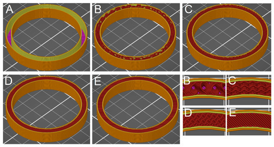
Figure 1.
A diagram of the structures of the prepared samples: (A)—0% filling density, (B)—20% filling density, (C)—50% filling density, (D)—80% filling density, (E)—100% filling density. The details of the respective individual types of filling are shown at the bottom right (labeled according to the specific sample).

Table 1.
Summarization of printing processes for all produced samples.
2.3. Methods
3D printing was performed on DeltiX (TriLAB, Czech Republic, nozzle size 0.4 mm), implementing the FFF technique. A working area of (250 × 300) mm2 with an integrated LCD was applied. Models were created and edited by the FreeCad software and exported in the .stl format (stereolithography). PrusaSlicer 2.2.0 was used to set the printing parameters and export them to a post-processing format (*g-code format).
The cross-section of filaments was characterized in terms of surface quality using a Keyence VHX-6000 optical microscope (Keyence, Itasca, MN, USA) and inspected at 2500× magnification with a focus on the additive distribution.
Additive powders were analyzed for particle size using Keyence VHX-6000 optical microscope (Keyence, Itasca, MN, USA) at 1000× magnification with subsequent analysis in the software ImageJ.
Analyzing the thermal behavior (mass change, heat flow) of the filament samples was followed by simultaneously performing a Thermogravimetry analysis (TGA) and Differential thermal analysis (DTA) under non-isothermal conditions, using a TGA 2 instrument (Mettler-Toledo, Columbus, OH, USA). The measurements were performed in a nitrogen atmosphere at a heating rate of 20 °C∙min−1, in the temperature range of 30–450 °C.
The determination of the additive content was carried out on the basis of the standard ČSN EN ISO 3451-1 [51]. Three replicates were used for determination. The procedure consisted of the determination of the combustible proportions when additive content (w, wt.%) used the calculation by Equation (1):
where m1 is the weight after combustion (g), m2 is the weight before combustion (g).
The morphology of samples was investigated with a scanning electron microscope (SEM) Quanta 450 FEG (FEI, Czech Republic) using a secondary electron detector. Observations were conducted on fractured surfaces at 20 kV accelerating voltage. Samples were placed on carbon tape and gold coated with a 7 nm thick layer.
X-ray powder diffraction (XRPD) data were collected at 40 kV and 40 mA with a Bragg–Brentano θ-θ diffractometer (Bruker D8 Advance, USA, Cu Kα radiation (λ = 1.5418 Å)). Data were collected in the angular range 8–80° 2θ counting 0.4 s for each step of 0.0102° 2θ. Rietveld refinements were used for quantitative phase analysis (QPA) using TOPAS 4.2 (Bruker AXS).
Magnetic properties were measured on a Remagraph C-500 measuring device (Magnet-Physik Dr. Steingroever Gmbh, Germany) designed to determine the quasi-stationary (DC) BH hysteresis characteristics of ferromagnetic materials. The configuration of the measuring system Remagraph version C500 is equipped with two electronic fluxmeters EF5. Furthermore, the Remagraph C500 is equipped with a precision DC power supply with a power of 320 VA and parameters ±40 V; ±8 A. The magnitude of the magnetic intensity and induction in the measured sample are determined, on the one hand, by the measured material itself and, on the other hand, by the winding configuration (Figure 2). The windings on the samples were made with an insulated copper conductor of full cross-section, where the conductor’s designation was U2 × 0.5.
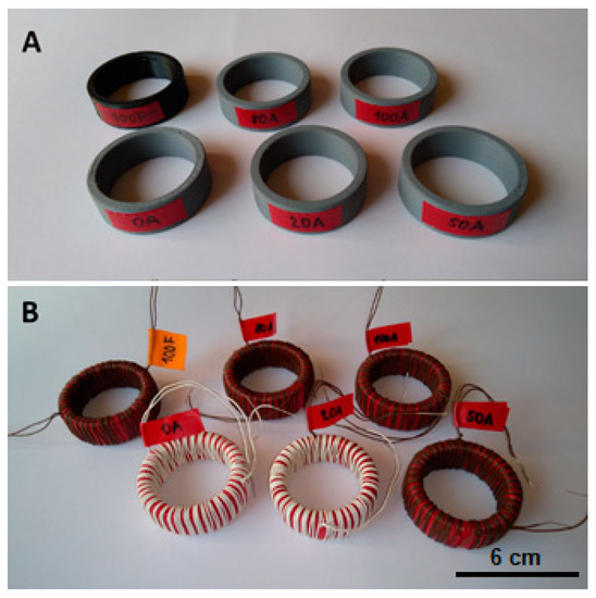
Figure 2.
Photographic images of the testing samples for the magnetic properties measurement, (A)—Samples after 3D printing, (B)—Samples with winding configuration.
In principle, the magnetizing winding of the measured toroid is connected to a direct current source. The current is very slowly increased and subsequently decreased to create a complete circulation of the entire BH characteristic. The measuring winding is connected to an electronic fluxmeter which records voltage jitters on the measuring winding and integrates this voltage. By a joint evaluation of the excitation current and the integrated voltage, we obtain the resulting BH characteristic—Either only the magnetization or the complete BH hysteresis characteristic [52,53]. An embodiment of the Remagraph measuring system and its basic block diagram is shown in Figure 3. Figure 4 shows the principle of determining the magnetic quantities and the individual connections in the toroidal sample and the measured material.
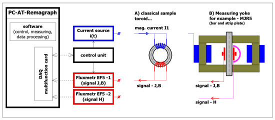
Figure 3.
Graphical illustration of remagraph—The basic block diagram of a measuring system.
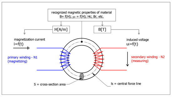
Figure 4.
The illustration of the principle of determination of magnetic quantities using toroidal samples.
A simulation program based on the principle of FEM methods, namely the Ansys-Maxwell software (Ansys Inc., Canonsburg, PA, USA), was used to evaluate the magnetic field and holding force of the typical configurations of the permanent magnet and the printed magnetic plastic disc. Ansys-Maxwell is an electromagnetic tool designed to analyze low-frequency problems and devices using the solution of general Maxwell’s equations. The actual simulation of the magnetic field was performed in the program Ansys-Maxwell using FEM calculation methods [54,55,56].
3. Results and Discussion
3.1. Characterization of Material
XRD analysis revealed that the applied magnetics additive was composed mainly of hematite (Iron(III) oxide; 70.7 ± 0.2 wt.%) with 29.3 ± 0.2 wt.% of rutile (Ti(II) dioxide) based on XRD analysis. Such a combination of mixed oxides compositions exhibits paramagnetic behavior at room temperature [57]. The mean particle size was calculated to be 160.2 ± 15.3 nm (see Figure S1). The additive content (determined using the combustion process) was found to be 3.11 ± 0.12 wt.%.
The melting point (Tm) of both PET-G filaments, with and without the content of metal oxides, were determined to select the correct processing temperatures of the extruder and the bed as well (Figure S2). The glass transition temperature for this material without additives is around 80 °C [58]. Setting the temperature around the glass transition temperature for bed temperatures is recommended. One of the first points mentioned in any extrusion discussion (FFF technology is based on the extrusion process) is the melt temperature. This is the only temperature that is absolute. The DTA-TGA technique is not sensitive to determine Tg; therefore, only Tm was determined. The Tm was determined to be 244.02 °C for the filament containing metal oxides and 235.87 °C for the reference sample.
The homogeneous distribution of this additive in the PET-G matrix was confirmed from its microscopic observations, as can be seen in Figure 5 and detailed in the enclosed inset figure. The SEM observations showed that applied metal oxides exhibit a high variety in shapes and sizes (Figure 6a). Nanosized particles together with micrometric agglomerates were observed. Observations at higher magnifications revealed that larger agglomerates were composed of nanosized, mainly spherulitic, particles (Figure 6b). The internal structure of the PET-G sample without metal particles is visualized in Figure 6c. Figure 6d confirmed the homogenous distributions of metal particles within a polymer matrix.
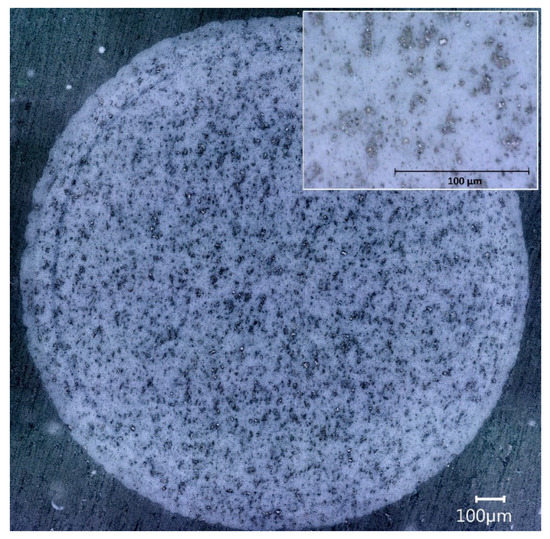
Figure 5.
Microscopic image of the microstructure of the used PET-G filament containing metal oxides.
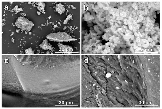
Figure 6.
The collection of SEM images: (a)—Particles of metal oxides observed at lower magnification, (b)—Microstructure of metal oxides particles observed at higher magnification, (c)—Internal structure of PET-G sample, (d)—Internal structure of PET-G sample containing additive.
3.2. Magnetic Properties
As expected, the prepared PET-G samples containing magnetic fillers showed paramagnetic behavior [59]. The measured BH hysteresis characteristic is thus reduced to a straight line, and the resulting characteristic magnetic parameter corresponds to the relative permeability. Figure 7 shows the magnetization characteristics for all types of produced samples with 0–100% filling density. The clear difference between samples 100A and 100F (REF) is visible. In the case of sample A, only small differences can be observed with the increasing filling density. A determined value of relative permeability was found to increase slightly with higher filling density: 1.24, 1.29, 1.34, 1.35, and 1.39 for samples 0A, 20A, 50A, 80A, and 100A, respectively. Such values were determined to be at least 18 % higher if compared with the REF sample (1.05).
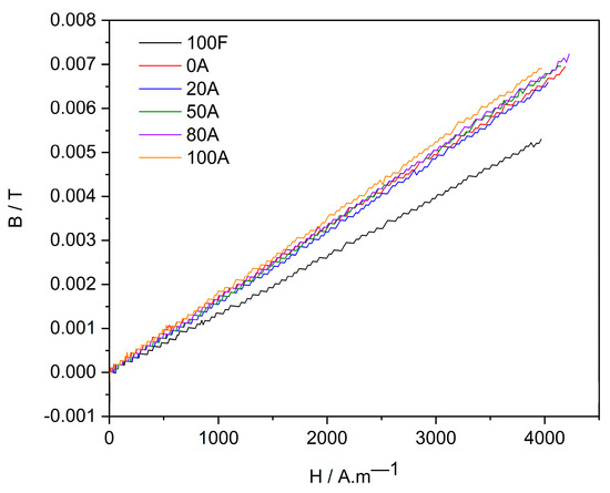
Figure 7.
Resulting in magnetization characteristics of individual samples.
3.3. Magnetic Field Simulation and Calculation of Force Effects
The basic possible usage of printed magnetic plastics is related to the emergence of a certain force effect on the finished material upon its exposure to an external magnetic field [60]. In common and technical practice, there are certainly applications where it is necessary to attach a general plastic structure to a magnet or other source of a magnetic field. Conversely, attaching the magnetic elements to the plastic base may also be beneficial. In simple terms, it may be an alternative to a sheet metal magnetic board. The key question for subsequent practical applications is how large can be the achieved force. The find the answer to this question, this subchapter presents the results of the magnetic field simulation and calculation of force effects on the model of the selected type configuration of a permanent magnet and type plastic plate corresponding to variants of printed PET-G with different levels of filling.
During the simulation, different distances of the magnet from the plastic plate, ranging from 0 to 5 mm, were considered. The model was conceived as 2D axisymmetric and corresponded to the cylindrical design of the permanent magnet and the plastic plate. The permanent magnet had a diameter of 20 mm and a height of 3 mm. The plastic plate with a magnetic filler had a diameter of 100 mm and a thickness of 5 mm. The surroundings of the model were air with a diameter of 240 mm and a height of 120 mm. The permanent magnet was considered to be the FeNdB type, version N35, with a coercive force (Hc) equal to 890 Ka·m−1. The design of the model is graphically visualized in Figure 8 and Figure 9, where the basic model for the zero distance of the magnet and the plastic plate is shown.
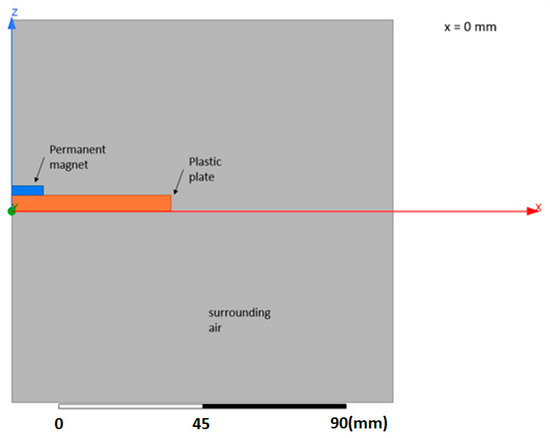
Figure 8.
The FEM model of the permanent magnet and plastic plate with a magnetic filler.
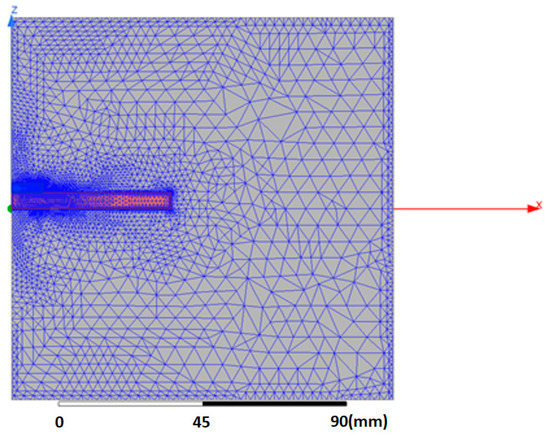
Figure 9.
An image of a computer network model.
The actual FEM calculation of the magnetic field distribution corresponds to a magnetostatic problem with excitation using permanent magnets [54,55,56].
The result of the simulations is the distributions of the magnetic field in the magnet and the plastic plate with the magnetic filler and the surrounding air. The distribution of magnetic field intensity (H) and magnetic induction (B) for the model with zero air gap are shown in Figure 10 and Figure 11, respectively. The magnitude of the applied force on the plastic plate is then obtained by post-processing calculation. An overview of the results of the calculated forces for different variants of plastic filling and different distances of the magnet from the plastic plate is given in Figure 12.
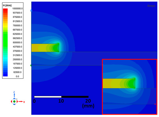
Figure 10.
The calculated magnetic field distribution—Magnetic field intensity H (A.m−1). The view in detail is shown in the inset.
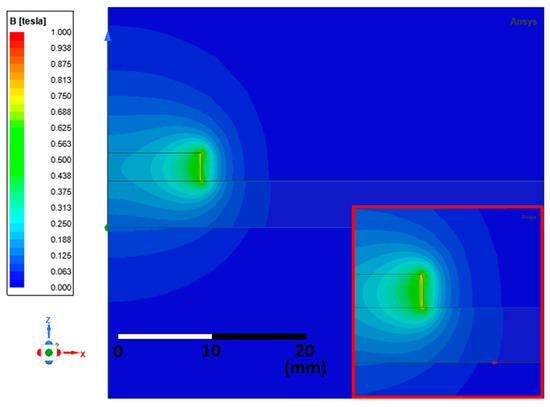
Figure 11.
The calculated magnetic field distribution—Magnetic induction B (T). The view in detail is shown in the inset.
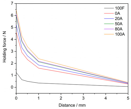
Figure 12.
The calculated magnitudes of holding forces acting on the plastic plate.
As reported in Figure 12, simulated holding forces calculated for different variants of magnetic filling of the plastic plate were, as expected, found to increase with higher infill density with determined values in the range from 4.5 to 6.5 N at zero distance. Such forces are sufficient to ensure a stable attachment of smaller or lighter objects. Thus, the prepared materials can produce components designed to conduct a magnetic flux or a small force interaction and thus attach a certain object. In practice, such elements can then be used in the construction of magnetic switches or sensors or for the production of components that homogenize the magnetic field of electric motors.
4. Conclusions
This work focused on determining the magnetic properties of PET-G containing magnetic additive based on Iron(III) and Titanium(II) oxides. The thermal analysis measurements were performed to characterize the thermal behavior of applied polyethylene-based filaments and to determine the correct set-up of processing temperatures. The products with different infill densities, and thus various internal architectures, were produced using Fused Filament Fabrication technology.
The paramagnetic properties were identified to be affected by different printed product densities, and relative magnetic permeability was calculated to be increased by up to 40% if samples 100F and 100A were compared. Finite Element Modelling was used to simulate the magnetic field simulations and to calculate the holding forces. Performed FEM model simulations on a typical configuration of a magnet and a plate with magnetic filler showed the creation of a force of around 5 N at zero air gap, which can ensure a stable attachment of objects of smaller dimensions or with lightweight constructions. From the point of view of 3D printing itself, it can be summarized that the price of production can be significantly decreased using the less dense structures due to saving on materials and printing time as well. As a final note, the presented results showed that the properties of produced samples could be tuned according to their desired applications, such as magnetic sensors, switches, and others.
It is thanks to choosing the right infill density of the product filling while maintaining the required properties that, as mentioned, it is possible to ensure a cheaper and faster production of shape-demanding samples with cheap FFF technology. The big advantage of this technology is that it is produced without the need to use expensive molds, and the technology is suitable for small-scale production.
Supplementary Materials
The following supporting information can be downloaded at: https://www.mdpi.com/article/10.3390/magnetochemistry9010002/s1; Figure S1: Image for analysis of additive particles using SW ImageJ; Figure S2: TGA graphs for both materials.
Author Contributions
Conceptualization, L.Z. and M.M.; methodology, M.M., L.Z. and R.Š.; software, M.M.; validation, R.Š., J.P. and R.S.; formal analysis, M.M., R.S. and J.P.; Investigation, M.M. and L.Z.; writing—original draft preparation, L.Z., R.Š. and M.M.; writing—review & editing, J.P. and R.Š.; visualization, J.Š.; project administration, J.Š.; funding acquisition, J.P. All authors have read and agreed to the published version of the manuscript.
Funding
This research was funded by the Institute of Technology and Business under project 05SVV2203 and the Czech Academy of Sciences, Institute of Theoretical and Applied Mechanics—RVO 68378297.
Institutional Review Board Statement
Not applicable.
Informed Consent Statement
Informed consent was obtained from all subjects involved in the study.
Data Availability Statement
Comparative data used in this study are available via reference links reported throughout the text part.
Conflicts of Interest
The authors declare no conflict of interest.
References
- Culmone, C.; Smit, G.; Breedveld, P. Additive manufacturing of medical instruments: A state-of-the-art review. Addit. Manuf. 2019, 27, 461–473. [Google Scholar] [CrossRef]
- Kessler, A.; Hickel, R.; Reymus, M. 3D printing in dentistry—State of the art. Oper. Dent. 2020, 45, 30–40. [Google Scholar] [CrossRef] [PubMed]
- Serra, T.; Mateos-Timoneda, M.A.; Planell, J.A.; Navarro, M. 3D printed PLA-based scaffolds: A versatile tool in regenerative medicine. Organogenesis 2013, 9, 239–244. [Google Scholar] [CrossRef] [PubMed]
- Rusling, J.F. Developing microfluidic sensing devices using 3D printing. ACS Sens. 2018, 3, 522–526. [Google Scholar] [CrossRef] [PubMed]
- Böckin, D.; Tillman, A.-M. Environmental assessment of additive manufacturing in the automotive industry. J. Clean. Prod. 2019, 226, 977–987. [Google Scholar] [CrossRef]
- Alexander, C. Streamlining automotive production with additive manufacturing. Quality 2018, 57, 37–39. [Google Scholar]
- Zhakeyev, A.; Wang, P.; Zhang, L.; Shu, W.; Wang, H.; Xuan, J. Additive manufacturing: Unlocking the evolution of energy materials. Adv. Sci. 2017, 4, 1700187. [Google Scholar] [CrossRef]
- Hambach, M.; Rutzen, M.; Volkmer, D. Properties of 3D-printed fiber-reinforced Portland cement paste. In 3D Concrete Printing Technology; Elsevier: Amsterdam, The Netherlands, 2019; pp. 73–113. [Google Scholar]
- Lille, M.; Nurmela, A.; Nordlund, E.; Metsä-Kortelainen, S.; Sozer, N. Applicability of protein and fiber-rich food materials in extrusion-based 3D printing. J. Food Eng. 2018, 220, 20–27. [Google Scholar] [CrossRef]
- Gibson, I.; Rosen, D.; Stucker, B.; Khorasani, M. Materials for additive manufacturing. In Additive Manufacturing Technologies; Springer: Berlin/Heidelberg, Germany, 2021; pp. 379–428. [Google Scholar]
- Williams, L.D.; Williams, L. Additive manufacturing or 3d scanning and printing. In Manufacturing Engineering Handbook; McGraw-Hill: New York, NY, USA, 2015. [Google Scholar]
- Laureto, J.; Tomasi, J.; King, J.A.; Pearce, J.M. Thermal properties of 3-D printed polylactic acid-metal composites. Prog. Addit. Manuf. 2017, 2, 57–71. [Google Scholar] [CrossRef]
- Alam, F.; Shukla, V.R.; Varadarajan, K.M.; Kumar, S. Microarchitected 3D printed polylactic acid (PLA) nanocomposite scaffolds for biomedical applications. J. Mech. Behav. Biomed. Mater. 2020, 103, 103576. [Google Scholar] [CrossRef]
- Tao, Y.; Liu, M.; Han, W.; Li, P. Waste office paper filled polylactic acid composite filaments for 3D printing. Compos. Part B Eng. 2021, 221, 108998. [Google Scholar] [CrossRef]
- Zander, N.E.; Gillan, M.; Lambeth, R.H. Recycled polyethylene terephthalate as a new FFF feedstock material. Addit. Manuf. 2018, 21, 174–182. [Google Scholar] [CrossRef]
- Dolzyk, G.; Jung, S. Tensile and fatigue analysis of 3D-printed polyethylene terephthalate glycol. J. Fail. Anal. Prev. 2019, 19, 511–518. [Google Scholar] [CrossRef]
- Mansour, M.; Tsongas, K.; Tzetzis, D.; Antoniadis, A. Mechanical and dynamic behavior of fused filament fabrication 3D printed polyethylene terephthalate glycol reinforced with carbon fibers. Polym. Plast. Technol. Eng. 2018, 57, 1715–1725. [Google Scholar] [CrossRef]
- Carrete, I.A.; Quiñonez, P.A.; Bermudez, D.; Roberson, D.A. Incorporating textile-derived cellulose fibers for the strengthening of recycled polyethylene terephthalate for 3D printing feedstock materials. J. Polym. Environ. 2021, 29, 662–671. [Google Scholar] [CrossRef]
- Małek, M.; Grzelak, K.; Łasica, W.; Jackowski, M.; Kluczyński, J.; Szachogłuchowicz, I.; Torzewski, J.; Łuszczek, J. Cement-glass composite bricks (CGCB) with interior 3D printed PET-G scaffolding. J. Build. Eng. 2022, 52, 104429. [Google Scholar] [CrossRef]
- Kechagias, J.D.; Fountas, N.A.; Ninikas, K.; Petousis, M.; Vidakis, N.; Vaxevanidis, N. Surface characteristics investigation of 3D-printed PET-G plates during CO2 laser cutting. Mater. Manuf. Process. 2022, 37, 1347–1357. [Google Scholar] [CrossRef]
- Soleyman, E.; Aberoumand, M.; Soltanmohammadi, K.; Rahmatabadi, D.; Ghasemi, I.; Baniassadi, M.; Abrinia, K.; Baghani, M. 4D printing of PET-G via FDM including tailormade excess third shape. Manuf. Lett. 2022, 33, 1–4. [Google Scholar] [CrossRef]
- Ferreira, I.; Vale, D.; Machado, M.; Lino, J. Additive manufacturing of polyethylene terephthalate glycol/carbon fiber composites: An experimental study from filament to printed parts. Proc. Inst. Mech. Eng. Part L J. Mater. Des. Appl. 2019, 233, 1866–1878. [Google Scholar] [CrossRef]
- Vidakis, N.; Petousis, M.; Maniadi, A.; Koudoumas, E.; Liebscher, M.; Tzounis, L. Mechanical properties of 3D-printed acrylonitrile–butadiene–styrene TiO2 and ATO nanocomposites. Polymers 2020, 12, 1589. [Google Scholar] [CrossRef]
- De León, A.S.; Domínguez-Calvo, A.; Molina, S.I. Materials with enhanced adhesive properties based on acrylonitrile-butadiene-styrene (ABS)/thermoplastic polyurethane (TPU) blends for fused filament fabrication (FFF). Mater. Des. 2019, 182, 108044. [Google Scholar] [CrossRef]
- Farcas, M.T.; Stefaniak, A.B.; Knepp, A.K.; Bowers, L.; Mandler, W.K.; Kashon, M.; Jackson, S.R.; Stueckle, T.A.; Sisler, J.D.; Friend, S.A. Acrylonitrile butadiene styrene (ABS) and polycarbonate (PC) filaments three-dimensional (3-D) printer emissions-induced cell toxicity. Toxicol. Lett. 2019, 317, 1–12. [Google Scholar] [CrossRef] [PubMed]
- Vidakis, N.; Petousis, M.; Maniadi, A.; Koudoumas, E.; Vairis, A.; Kechagias, J. Sustainable additive manufacturing: Mechanical response of acrylonitrile-butadiene-styrene over multiple recycling processes. Sustainability 2020, 12, 3568. [Google Scholar] [CrossRef]
- Zander, N.E.; Gillan, M.; Burckhard, Z.; Gardea, F. Recycled polypropylene blends as novel 3D printing materials. Addit. Manuf. 2019, 25, 122–130. [Google Scholar] [CrossRef]
- Jin, M.; Neuber, C.; Schmidt, H.-W. Tailoring polypropylene for extrusion-based additive manufacturing. Addit. Manuf. 2020, 33, 101101. [Google Scholar] [CrossRef]
- Vidakis, N.; Petousis, M.; Tzounis, L.; Maniadi, A.; Velidakis, E.; Mountakis, N.; Papageorgiou, D.; Liebscher, M.; Mechtcherine, V. Sustainable additive manufacturing: Mechanical response of polypropylene over multiple recycling processes. Sustainability 2021, 13, 159. [Google Scholar] [CrossRef]
- Bachhar, N.; Gudadhe, A.; Kumar, A.; Andrade, P.; Kumaraswamy, G. 3D printing of semicrystalline polypropylene: Towards eliminating warpage of printed objects. Bull. Mater. Sci. 2020, 43, 171. [Google Scholar] [CrossRef]
- Reich, M.J.; Woern, A.L.; Tanikella, N.G.; Pearce, J.M. Mechanical properties and applications of recycled polycarbonate particle material extrusion-based additive manufacturing. Materials 2019, 12, 1642. [Google Scholar] [CrossRef]
- Fang, L.; Yan, Y.; Agarwal, O.; Seppala, J.E.; Hemker, K.J.; Kang, S.H. Processing-structure-property relationships of bisphenol-A-polycarbonate samples prepared by fused filament fabrication. Addit. Manuf. 2020, 35, 101285. [Google Scholar] [CrossRef]
- Calafel, I.; Aguirresarobe, R.H.; Peñas, M.I.; Santamaria, A.; Tierno, M.; Conde, J.I.; Pascual, B. Searching for rheological conditions for FFF 3D printing with PVC based flexible compounds. Materials 2020, 13, 178. [Google Scholar] [CrossRef]
- Gray, R.L. Hindered amine light stabilizers: Recent developments. Plast. Addit. 1998, 1, 360–371. [Google Scholar]
- Pritchard, G. Plastics Additives: An AZ Reference; Springer Science & Business Media: Berlin/Heidelberg, Germany, 2012; Volume 1, ISBN 9401158622. [Google Scholar]
- Sharma, K. Effect of FFF Process Parameters on Density and Mechanical Properties of PET-G and Carbon Fiber Reinforced PET-G Composites. Master’s Thesis, University of Manitoba, Winnipeg, MB, Canada, 2021. [Google Scholar]
- Basurto-Vázquez, O.; Sánchez-Rodríguez, E.P.; McShane, G.J.; Medina, D.I. Load distribution on PET-G 3D prints of honeycomb cellular structures under compression load. Polymers 2021, 13, 1983. [Google Scholar] [CrossRef] [PubMed]
- Vinyas, M.; Athul, S.J.; Harursampath, D.; Thoi, T.N. Experimental evaluation of the mechanical and thermal properties of 3D printed PLA and its composites. Mater. Res. Express 2019, 6, 115301. [Google Scholar] [CrossRef]
- Gopathi, P.; Surve, P. Possibilities and Limitations of using Production Waste PET and PES Materials in Additive Manufacturing (3D Printing Technology). Master’s Thesis, Halmstad University, Halmstad, Sweden, 2017. [Google Scholar]
- Bernasconi, R.; Natale, G.; Levi, M.; Magagnin, L. Electroless plating of NiP and Cu on polylactic acid and polyethylene terephthalate glycol-modified for 3D printed flexible substrates. J. Electrochem. Soc. 2016, 163, D526. [Google Scholar] [CrossRef]
- Equbal, A.; Sood, A.K. Metallization on FDM parts using the chemical deposition technique. Coatings 2014, 4, 574–586. [Google Scholar] [CrossRef]
- Domenech, S.C.; Lima, E., Jr.; Drago, V.; De Lima, J.C.; Borges, N.G., Jr.; Avila, A.O.V.; Soldi, V. Electroless plating of nickel–phosphorous on surface-modified poly (ethylene terephthalate) films. Appl. Surf. Sci. 2003, 220, 238–250. [Google Scholar] [CrossRef]
- Fischer, N.A.; Robinson, A.L.; Lee, T.J.; Calascione, T.M.; Koerner, L.; Nelson-Cheeseman, B.B. Magnetic annealing of extruded thermoplastic magnetic elastomers for 3D-Printing via FDM. J. Magn. Magn. Mater. 2022, 553, 169266. [Google Scholar] [CrossRef]
- Habibi, M.R.; Ghassemi, M.; Hamedi, M.H. Analysis of high gradient magnetic field effects on distribution of nanoparticles injected into pulsatile blood stream. J. Magn. Magn. Mater. 2012, 324, 1473–1482. [Google Scholar] [CrossRef]
- Braun, U.; Schartel, B. Flame Retardancy Mechanisms of Aluminium Phosphinate in Combination with Melamine Cyanurate in Glass-Fibre-Reinforced Poly(1,4-butylene terephthalate). Macromol. Mater. Eng. 2008, 293, 206–217. [Google Scholar] [CrossRef]
- Tumanski, S. Handbook of Magnetic Measurements; CRC Press: Boca Raton, FL, USA, 2016; ISBN 1439829527. [Google Scholar]
- Fiorillo, F. Characterization and Measurement of Magnetic Materials; Academic Press: Cambridge, MA, USA, 2004; ISBN 0080528929. [Google Scholar]
- Jiles, D. Introduction to Magnetism and Magnetic Materials; Chapman: Orange, CA, USA, 1991. [Google Scholar]
- Hilzinger, R.; Rodewald, W. Magnetic Materials; Vacuumschmeltze GmbH Co., KG: Hanau, Germany, 2013. [Google Scholar]
- Krishnan, K.M. Fundamentals and Applications of Magnetic Materials; Oxford University Press: Oxford, UK, 2016; ISBN 0199570442. [Google Scholar]
- ČSN EN ISO 3451-1; Plasty—Stanovení Popela—Část 1: Obecné Metody. UNMZ: Praha, Czech Republic, 2019.
- Steingroever, E.; Ross, G. Magnetic Measuring Techniques. Magnet-Physic Köln 1997, 1, 997. [Google Scholar]
- International Electrotechnical Commission. IEC 60404-4:1995+AMD1:2000+AMD2:2008, Magnetic Materials—Part 4: Methods of Measurement of d.c. Magnetic Properties of Magnetically Soft Materials; IEC—International Electrotechnical Commission: Geneva, Switzerland, 2008. [Google Scholar]
- Marek, M. Numerical computation of magnetic field and inductivity of power reactor with respect of real magnetic properties of iron core. In Scientific Computing in Electrical Engineering; Springer: Berlin/Heidelberg, Germany, 2006; pp. 233–239. [Google Scholar]
- Jin, J.-M. The Finite Element Method in Electromagnetics; John Wiley & Sons: Hoboken, NJ, USA, 2015; ISBN 1118842022. [Google Scholar]
- Bastos, J.P.A.; Sadowski, N. Electromagnetic Modeling by Finite Element Methods; CRC Press: Boca Raton, FL, USA, 2003; ISBN 0203911172. [Google Scholar]
- Wang, X.H.; Li, J.-G.; Kamiyama, H.; Katada, M.; Ohashi, N.; Moriyoshi, Y.; Ishigaki, T. Pyrogenic iron (III)-doped TiO2 nanopowders synthesized in RF thermal plasma: Phase formation, defect structure, band gap, and magnetic properties. J. Am. Chem. Soc. 2005, 127, 10982–10990. [Google Scholar] [CrossRef] [PubMed]
- Dupaix, R.B.; Boyce, M.C. Finite strain behavior of poly (ethylene terephthalate)(PET) and poly (ethylene terephthalate)-glycol (PETG). Polymer 2005, 46, 4827–4838. [Google Scholar] [CrossRef]
- Bransden, B.H.; Joachain, C.J. Physics of Atoms and Molecules; Pearson Education India: Bengaluru, India, 2003; ISBN 8177582798. [Google Scholar]
- Brauer, J.R. Magnetic Actuators and Sensors; John Wiley & Sons: Hoboken, NJ, USA, 2006; ISBN 0471777706. [Google Scholar]


Disclaimer/Publisher’s Note: The statements, opinions and data contained in all publications are solely those of the individual author(s) and contributor(s) and not of MDPI and/or the editor(s). MDPI and/or the editor(s) disclaim responsibility for any injury to people or property resulting from any ideas, methods, instructions or products referred to in the content. |
© 2022 by the authors. Licensee MDPI, Basel, Switzerland. This article is an open access article distributed under the terms and conditions of the Creative Commons Attribution (CC BY) license (https://creativecommons.org/licenses/by/4.0/).