Abstract
The magnetic stray field is an unavoidable consequence of magnetic multilayers, which may have a significant influence on the performance of spintronic devices. Based on Maxwell’s magnetostatics theory, here we numerically calculated the distributions of magnetic stray fields and self-demagnetizing fields in a series of patterned multilayer thin-film structures with either an in-plane or a perpendicularly magnetized ferromagnetic layer. The stray field above the ferromagnetic layer is inhomogeneous, showing the dramatic changes near the sample edge, but the uniformity in the center region could be improved with the increasing sample size. The stray field strength tends to zero for large samples, increases with the increase in the hard-layer thickness, and decreases with the increase in the distance D away from the ferromagnetic layer. In the multilayer samples, the separately simulated stray field and self-demagnetizing field within the soft layer agree well with the classic magnetostatic relationship of . For the in-plane magnetized trilayer sample, the magnetic-flux density within the soft ferromagnetic layer slightly decreases in the antiparallel magnetization alignment and increases in the parallel alignment state with the increase in the intermediate non-magnetic-layer thickness. In contrast, for the sample with the perpendicular magnetization, the magnetic-flux density decreases as the non-magnetic layer is thickened for both the antiparallel and parallel state. This study may provide a theoretical basis for the design of thin-film spintronic devices.
1. Introduction
The distribution of the magnetic dipolar or stray fields around thin-film nanostructures is crucial for various applications, including magnetic sensors [1], field-emission guns [2], magnetic-force microscopy [3], 2D field effect transistors [4], magnetic storage [1,5], and magnetic random access memory (MRAM) [6]. The magnetostatic field and self-demagnetizing field generated by the large-size magnetic thin film are often ignored. However, the magnetic field becomes pronounced for small-size devices, which may lead to inhomogeneity in magnetic tunnel junctions and may have a significant influence on the magnetic properties, thermal stability, and switching characteristics [7,8]. In addition, the cross-talk between magnetic elements due to the stray fields from their ferromagnetic layers cannot be ignored for integration. The core parts of these devices (e.g., magnetic tunnel junction or spin valves) consist of two ferromagnetic (FM) layers sandwiching a non-magnetic (NM) tunnel barrier, as illustrated in Figure 1a, where the upper magnetic layer (Layer A) is a soft layer whose magnetization is easy to rotate by external magnetic field or spin-polarized current, and the lower magnetic layer (Layer B) is the hard layer whose magnetization is fixed by adding an antiferromagnetic (AF) layer to provide a stable exchange bias field. In this case, the hard layer could generate a magnetic stray field acting at the position of the soft layer, naturally resulting in an asymmetry (offset) of hysteresis loop or switching current [8,9,10,11]. Such asymmetry is definitely undesirable for the applications in magnetic sensors or memory devices. For the applications of magnetic sensors, the stray field generated by the pinned layer (hard) on the free layer is a key factor for the optimization performance of the magnetic sensors. In order to reduce or eliminate such stray fields, normally a carefully designed synthetic antiferromagnetic (SAF) layer or pinned layer with the AF layer is required to replace the single hard layer [9,12,13]. On the other hand, the dipolar stray field sometimes needs to be amplified. For example, the dipolar interaction can also be used to synchronize two spin-torque oscillators [14,15] or to develop spin-wave directional couplers [16,17,18]. Therefore, understanding stray fields is extremely important for the engineering of spintronic devices.
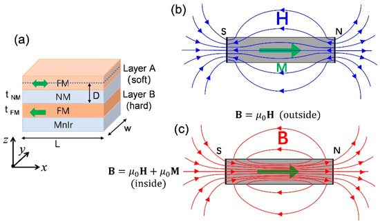
Figure 1.
(a) The sketch of magnetic tunnel junctions. The sample lateral dimension is L × w. The free layer and pinned layer are labelled as Layer A and Layer B, respectively. The tunnel barrier is labelled as NM spacer. t is the film thickness. The lateral section (blue dotted line) at the center of the soft layer is the detection window of the stray fields emanating from the uniformly magnetized hard layer. D is the distance. (b) Illustration of magnetic dipolar field H lines (blue curves) generated by a magnetic thin film, where M indicates the magnetization vector (green arrow). (c) The corresponding distribution of magnetic induction field B lines (red curves). Inside the magnet sample and the outside .
The microscopic principle of the magnetic stray fields is derived from the dipolar field of atoms. Generally, the magnetic stray fields in the magnetic thin-film samples can be studied by Maxwell’s magnetostatics [3,19] or micromagnetic simulations (e.g., OOMMF [20] or MuMax3 [21]). Very recently, the influence of stray fields for the practical MRAM application with the element size smaller than 50 nm tunnel junctions has been modelled at atomic-level precision by VAMPIRE code [12], in which the stray fields caused by both the patterning defect and the non-collinear antiferromagnets have been well discussed. Interestingly, the bulk magnetization of an antiferromagnet is essentially zero, but at the nanoscale atomic lattice defects and the non-collinear nature of the antiferromagnetic spins may also lead to a magnetic stray field, which may be particularly important for nanoscale magnetic sensors or memory devices.
In this paper, in order to comprehensively analyze the scalability of the dipolar magnetic field effect, we performed a series of simulations in the multilayer samples with the in-plane or perpendicular magnetization. The samples are patterned in a rectangular shape with a fixed lateral aspect ratio of 1:2, and the sample size (short axis) varies from 50 nm to 0.5 μm. The spatial distribution of the magnetic-flux density as well as the separated stray field and the self-demagnetizing field are modelled as a function of sample size, ferromagnetic layer thickness, separated distance, and different magnetization-alignment configurations.
2. Theoretical Model and Method
It is well known that for a magnetic thin film magnetized along the x direction in the film plane by a uniform external magnetic field, a north (N) pole (with positive magnetic charges) is formed at right and south (S) pole at left, as illustrated in Figure 1b. Consequently, the magnetic-charge-induced dipole fields (H lines) radiate out from the N pole to the S pole, both from the outside and inside of the sample [22]. The magnetic circuits of the dipole field H lines are closed except their direction suddenly reverses at the magnetic poles. The inside dipole field is named the self-demagnetizing field , while the outside is called the stray field. The self-demagnetizing field is not uniform and opposes the magnetization , but its strength can never exceed . In the classic magnetostatic relationship of is the magnetic induction strength vector and is the vacuum permeability. Thus, within the sample we have , while for the outside , as shown in Figure 1c. The flux density of B inside the magnet is therefore less than but in the same direction, so that the circuits of B lines are closed. In addition, the B lines depart or diverge toward the magnetic poles, and the flux density of B near the edges is less than that at the center of the sample. This is caused by the fact that the is stronger near the poles and has the minimum at the center. The uniform character of the self-demagnetizing effect strongly influences the behavior of magnetic thin films and is very important in possible practical spintronic devices.
We consider ferromagnetic compounds with a given magnetization M. The law of together with Maxwell’s equations divB = 0 and curlH = 0 yield the Poisson’s equations for the scalar magnetic potential and the components of the vector potential, respectively. From the Biot–Savart law, the magnetic-flux density B with an equivalent surface current density (n is the surface normal pointing out the sample) can be derived analytically, e.g., for a cuboid sample with perpendicular magnetization [3]:
where L, w, and t are the geometry parameters of the sample. Based these theories, numerically, the finite-element-based software of COMSOL can be used to calculate the stray field distribution [7,23]. Here, we consider two types of patterned samples: one is the in-plane (IP) uniformly magnetized permalloy (Ni80Fe20) with saturation magnetization MS = 0.8 MA/m [24], and the other one is the perpendicularly (Perp.) magnetized sample FePt with MS = 1.1 MA/m [25,26,27,28].
3. Results
Firstly, in order to study the stray fields emanating from the fixed hard layer (Layer B), we performed a series of simulations in which the soft layer (Layer A) is omitted but the detection window is located at the center of the soft layer, as illustrated in Figure 1a. The thickness of the uniformly magnetized hard layer is fixed at 10 nm, and the detection window is in the position with D = 4.5 nm. Figure 2a shows the x-component distribution of the stray fields at the detection window for the in-plane magnetized sample (magnetized along +x direction), where the sample size is 500 nm × 1000 nm. As expected, the radial component of stray field Bx varies spatially, whose strength near the sample edges is stronger than that in the center region, and it shows positive and negative sign changes at both edges [7]. This feature remains with the increase in sample size, as shown in Figure 2b,d. For a better comparison, the horizontal axis in Figure 2d has been normalized with the sample length as X/L. The sample size is changed with a fixed aspect ratio of L/w = 1:2, where the length L varies from 50 to 500 nm. The stray field strength Bx,c in the center region significantly decreases from 0.0955 T to 0.000346 T with the increase in sample size. Similarly, for the perpendicularly magnetized sample (magnetized along +z direction), the vertical component of stray field Bz also shows sensitive changes at the surrounding edges and an almost constant value in the center region, as shown in Figure 3a. As the film is enlarged, the stray field strength gradually concentrates at the edge region while its strength Bz,c in the center region gradually decreases from 0.175 T to 0.02 T. Figure 2d and Figure 3c show the variation trend of the maximum and minimum strength of the stray fields. This size-dependent feature of the stray fields suggests that patterning only the soft layer and not the hard-pinned layer of the samples could reduce the influence of stray fields and improve its uniformity, which are helpful to solve the problem of asymmetric or offset switching in the magnetic sensors or memory application [9].
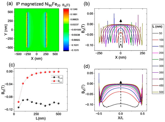
Figure 2.
Scalability of stray fields in samples with in-plane anisotropy. (a) Distribution of stray field (Bx) at the position of D = 4.5 nm; (b) the Bx varies with the sample size from L = 50 nm to 500 nm. (c) The maximum values at edge (Bx,m, black balls) and minimum at center (Bx,c, red balls) stray fields as a function of sample size. (d) The horizontal axis is normalized with L. The dash-line arrows indicate the trend of L increasing.

Figure 3.
Scalability of stray fields in samples with perpendicular anisotropy. (a) Distribution of the vertical component of stray field (Bz) at the position of D = 4.5 nm; (b) calculated stray-field dependence on the size of samples. The dash-line curve is calculated from Equation (1) for the sample with size of L = 50 nm. (c) The maximum values at edge (Bz,m, black balls) and minimum at center (Bz,c, red balls) stray fields as a function of sample size.
The thickness of the hard layer is also a key factor to influence the stray fields [12]. Figure 4a,c respectively show the thickness-dependent variation of stray fields for the two types of samples. In both cases, the strength of magnetic stray fields constantly increases with the thickness increasing. For the in-plane magnetized sample, as the thickness increases, the inhomogeneous distribution of stray fields becomes pronounced, showing the field at both edges is much larger than that in the center region, see Figure 4a. In contrast, for the perpendicularly magnetized sample, the uniform distribution region of stray fields gradually increases with the thickness increasing. The field strength Bz,c in the center region gradually increases from 0.101 T to 0.587 T, with the hard-layer thickness tFM increasing from 50 nm to 500 nm, as shown in Figure 4c.
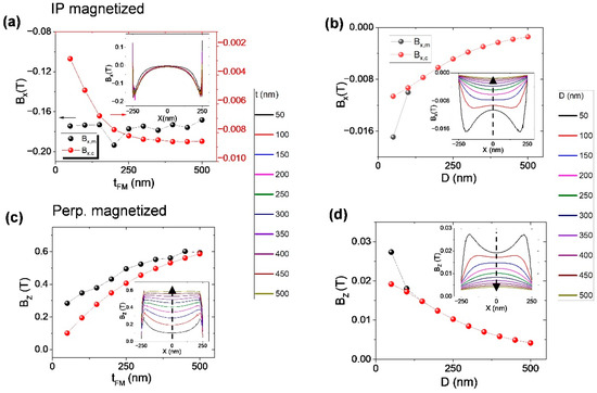
Figure 4.
(a,c) The thickness dependence of max strength of stray fields (black curve) and min strength at the center position (red curve) at a fixed distance of D = 4.5 nm. (b,d) The spatial distance D dependence, where the sample size is fixed at L = 5 nm. The insets show the overall distribution of stray fields at the detection window.
The magnetic-stray-field distribution around a permanent magnet is strongly related to the spatial position above the magnet (i.e., distance) [29,30]. We find that in our case both the max and min values of the stray fields gradually decrease with the increase in distance D, as shown in Figure 4b,d. The stray-field curves gradually become smooth, and the field strength decreases from 0.01061 T (in-plane magnetized sample) and 0.01918 T (perpendicularly magnetized sample) and tends to zero, with the D increasing from 50 nm to 500 nm.
The spatially varying stray fields emanating from the hard layer could cause different mechanisms of magnetization reversal, showing that the antiparallel (AP) to parallel (P) switching starts near the edge while the P to AP switching begins in the interior of the soft layer [7]. In order to check the stray-field difference between the AP and P magnetization alignment, we ran the simulation with different magnetization configurations. The results are shown in Figure 5. Here, we suppose the thickness of the Layer A is 5 nm and that of the Layer B is 10 nm. In order to exclude the influence of the self-demagnetizing field, the magnetic film at the measured position is temporarily removed. It can be seen that the direction of the stray field acting on the hard layer (e.g., Layer A to B, black curves) is reversed because the magnetization orientation of Layer A is reversed during the transition between the AP and P alignments, but the stray field strength remains unchanged. On the other side, although the strength in the perpendicular sample is larger than that in the in-plane magnetized sample, the inhomogeneous distributions of the stray fields acting on the lateral position at the center of the soft layer are generally similar.
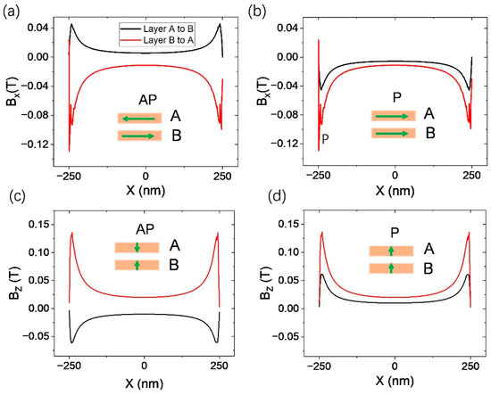
Figure 5.
The stray fields generated by the soft layer (Layer A) and the hard layer (Layer B) acting on each other. The thickness of Layer A, Layer B, and NM spacer is 5 nm, 10 nm, and 2 nm, respectively. The red curves show the stray fields acting on the soft layer and the black curves show the reversed action. (a,c) for the antiparallel magnetization state and (b,d) for the parallel magnetization state.
In addition to the magnetic stray field emanating from the hard layer, the self-demagnetizing field of the soft layer could also influence the magnetization switching. Figure 6 shows the magnetic-flux density within the soft layer of the samples. Here, we suppose that the magnetization vectors are in the antiparallel alignment configurations. The enlarged snapshots show the details of the transition region near the boundary of the soft layer. The width of the magnetic field transition region of in-plane magnetized samples is similar to that of perpendicularly magnetized samples. The simulated magnetic fields within the soft layer in Figure 6b,d confirm the relationship of , where is the self-demagnetizing field and where and are almost equal to their saturation magnetization for both the in-plane and perpendicularly magnetized soft layer.
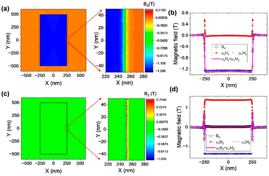
Figure 6.
(a,c) The spatial distribution of magnetic-flux density B. (b,d) The simulated B, H, and M distribution as a function of x coordinates of Layer A. They are consistent with the relationship of . Top panel is for the in-plane magnetized samples, and the bottom panel is for the perpendicular case.
Moreover, the magnetic-flux density has also been studied as a function of the NM-layer thickness between the two FM layers. In our simulations, the NM layer is treated as an air spacer. Figure 7 shows the simulated magnetic-flux density B at the central position of Layer A and Layer B in the cases with antiparallel or parallel magnetization alignments, where the spacer thickness varies from 10 nm to 50 nm, the Layer B is 10 nm thick, and the Layer A is 5 nm thick. It has been demonstrated that the stray field decreases with the increase in detection window distance D (see Figure 4b,d). But for the in-plane magnetized trilayer sample, the Layer-B-induced stray field has the same or opposite direction with the magnetization vector of Layer A in the antiparallel or parallel alignment state, respectively. Thus, the magnetic-flux density gradually decreases as the NM layer is thickened in the antiparallel state and increases in the parallel state, as shown in Figure 7a,b, respectively. In contrast, for the perpendicularly magnetized trilayer sample, the stray field has an opposite direction (see Figure 5c,d) in the antiparallel alignment state and the same direction in the parallel alignment state. Thus, in the parallel state, as shown in Figure 7d, the B fields in both Layer A and Layer B decrease, with the NM thickness increasing from 10 nm to 50 nm. However, in the antiparallel state, the B field in Layer A slightly decreases from 0.00992 T to 0.00907 T as the NM layer is thickened. However, in Layer B it increases from 0.01006 T to 0.01048 T, see Figure 7c.
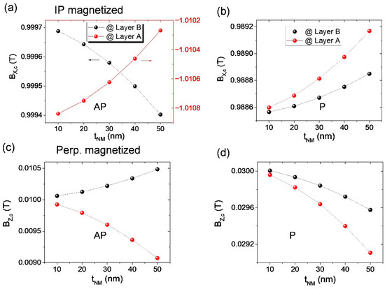
Figure 7.
The dependence of magnetic-flux density B field on the NM-layer thickness for the in-plane magnetized trilayer sample (a,b) and perpendicularly magnetized trilayer sample (c,d), where (a,c) for the anti-parallel state and (b,d) for the parallel state.
4. Conclusions
In conclusion, we have presented a comprehensive theoretical study of the distribution of the magnetic stray field and the self-demagnetizing field in a trilayer system with in-plane or perpendicular anisotropy. Based on the theory of magnetostatics, the magnetic-stray-field distribution above an in-plane or perpendicularly magnetized magnetic film was discussed, which strongly depends on the sample size, thickness, and distance away from the sample surface. We find that the magnetic stray field is inhomogeneous, showing that the field near the sample edge is stronger than that in the center region. The numerical simulation result agrees well with the analytical calculation. The uniformity of stray fields in the center region could be improved with the increasing sample size, and the field strength tends to zero for large samples. In addition, the stray field strength increases with the increase in the hard-layer thickness and decreases with the increasing distance away from the hard layer. In the multilayer samples, we have separately calculated the magnetic stray field and the self-demagnetizing field, and the classic relationship of is confirmed. But for the trilayer sample with in-plane magnetization, the magnetic-flux density within the soft ferromagnetic layer (including stray field and self-demagnetizing field) slightly decreases in the AP and increases in the P alignment state with the increase in the NM-layer thickness. In contrast, for the sample with the perpendicular magnetization, the magnetic-flux density always decreases with the increasing thickness of the NM layer for both the AP and P states. All these findings may provide guidance for engineering multilayer spintronics devices.
Author Contributions
Conceptualization, Y.L.; data curation, S.Z. and Y.W.; formal analysis, S.Z., Y.W. and Y.L.; writing—original draft preparation, S.Z.; and writing—review and editing, Y.L. All authors have read and agreed to the published version of the manuscript.
Funding
This work is supported by the National Natural Science Foundation of China (Grant Nos. 51971161, 12274322).
Institutional Review Board Statement
Not applicable.
Informed Consent Statement
Not applicable.
Data Availability Statement
The study did not report any data.
Conflicts of Interest
The authors declare no conflict of interest. The funders had no role in the design of the study; in the collection, analyses, or interpretation of data; in the writing of the manuscript, or in the decision to publish the results.
References
- Parkin, S.; Jiang, X.; Kaiser, C.; Panchula, A.; Roche, K.; Samant, M. Magnetically engineered spintronic sensors and memory. Proc. IEEE 2003, 91, 661–680. [Google Scholar] [CrossRef]
- De Jonge, N.; Lamy, Y.; Schoots, K.; Oosterkamp, T.H. High brightness electron beam from a multi-walled carbon nanotube. Nature 2002, 420, 393–395. [Google Scholar] [CrossRef] [PubMed]
- Norpoth, J.; Dreyer, S.; Jooss, C. Straightforward field calculations for uniaxial hardmagnetic prisms: Stray field distributions and dipolar coupling in regular arrays. J. Phys. D Appl. Phys. 2007, 41, 025001. [Google Scholar] [CrossRef]
- Tantardini, C.; Kvashnin, A.G.; Gatti, C.; Yakobson, B.I.; Gonze, X. Computational Modeling of 2D Materials under High Pressure and Their Chemical Bonding: Silicene as Possible Field-Effect Transistor. ACS Nano 2021, 15, 6861–6871. [Google Scholar] [CrossRef] [PubMed]
- Mao, S.; Chen, Y.; Liu, F.; Chen, X.; Xu, B.; Lu, P.; Patwari, M.; Xi, H.; Chang, C.; Miller, B.; et al. Commercial TMR heads for hard disk drives: Characterization and extendibility at 300 gbit 2. IEEE Trans. Magn. 2006, 42, 97–102. [Google Scholar]
- Slaughter, J.M.; Rizzo, N.D.; Janesky, J.; Whig, R.; Mancoff, F.B.; Houssameddine, D.; Sun, J.J.; Aggarwal, S.; Nagel, K.; Deshpande, S.; et al. High density ST-MRAM technology (Invited). In Proceedings of the 2012 International Electron Devices Meeting, San Francisco, CA, USA, 10–13 December 2012; pp. 29.23.21–29.23.24. [Google Scholar]
- Bapna, M.; Piotrowski, S.K.; Oberdick, S.D.; Li, M.; Chien, C.-L.; Majetich, S.A. Magnetostatic effects on switching in small magnetic tunnel junctions. Appl. Phys. Lett. 2016, 108, 022406. [Google Scholar] [CrossRef]
- Ikeda, S.; Miura, K.; Yamamoto, H.; Mizunuma, K.; Gan, H.D.; Endo, M.; Kanai, S.; Hayakawa, J.; Matsukura, F.; Ohno, H. A perpendicular-anisotropy CoFeB–MgO magnetic tunnel junction. Nat. Mater. 2010, 9, 721–724. [Google Scholar] [CrossRef]
- Devolder, T.; Carpenter, R.; Rao, S.; Kim, W.; Couet, S.; Swerts, J.; Kar, G.S. Offset fields in perpendicularly magnetized tunnel junctions. J. Phys. D Appl. Phys. 2019, 52, 274001. [Google Scholar] [CrossRef]
- Liu, Y.; Zhang, Z.; Freitas, P.P.; Martins, J.L. Current-induced magnetization switching in magnetic tunnel junctions. Appl. Phys. Lett. 2003, 82, 2871–2873. [Google Scholar] [CrossRef]
- Liu, Y.; Zhang, Z.; Wang, J.; Freitas, P.P.; Martins, J.L. Current-induced switching in low resistance magnetic tunnel junctions. J. Appl. Phys. 2003, 93, 8385–8387. [Google Scholar] [CrossRef]
- Jenkins, S.; Meo, A.; Elliott, L.E.; Piotrowski, S.K.; Bapna, M.; Chantrell, R.W.; Majetich, S.A.; Evans, R.F.L. Magnetic stray fields in nanoscale magnetic tunnel junctions. J. Phys. D Appl. Phys. 2019, 53, 044001. [Google Scholar] [CrossRef]
- Tantardini, C.; Benassi, E. Crystal structure resolution of an insulator due to the cooperative Jahn–Teller effect through Bader’s theory: The challenging case of cobaltite oxide Y114. Dalton Trans. 2018, 47, 5483–5491. [Google Scholar] [CrossRef] [PubMed]
- Chen, H.-H.; Zeng, L.; Zhao, W.; Liu, Y. Phase-Locking of Spin-Torque Nano-Oscillator Pairs by Magnetic Dipolar Coupling in Electrical Serial Connection. SPIN 2018, 8, 1850013. [Google Scholar] [CrossRef]
- Belanovsky, A.D.; Locatelli, N.; Skirdkov, P.N.; Araujo, F.A.; Grollier, J.; Zvezdin, K.A.; Cros, V.; Zvezdin, A.K. Phase locking dynamics of dipolarly coupled vortex-based spin transfer oscillators. Phys. Rev. B 2012, 85, 100409. [Google Scholar] [CrossRef]
- Wang, Q.; Pirro, P.; Verba, R.; Slavin, A.; Hillebrands, B.; Chumak, A.V. Reconfigurable nanoscale spin-wave directional coupler. Sci. Adv. 2018, 4, e1701517. [Google Scholar] [CrossRef]
- Wang, Q.; Kewenig, M.; Schneider, M.; Verba, R.; Kohl, F.; Heinz, B.; Geilen, M.; Mohseni, M.; Lägel, B.; Ciubotaru, F.; et al. A magnonic directional coupler for integrated magnonic half-adders. Nat. Electron. 2020, 3, 765–774. [Google Scholar] [CrossRef]
- Sasaki, H.; Mikoshiba, N. Directional coupling of magnetostatic surface waves in a layered structure of YIG films. J. Appl. Phys. 1981, 52, 3546–3552. [Google Scholar] [CrossRef]
- Jackson, J.D. Classical Electrodynamic, 3rd ed.; John Wiley & Sons, Inc.: New York, NY, USA, 1998. [Google Scholar]
- Donahue, M.J.; Porter, D.G. User’s Guide; National Institute of Standards and Technology: Gaithersburg, MD, USA, 2022. [Google Scholar]
- Vansteenkiste, A.; Leliaert, J.; Dvornik, M.; Helsen, M.; Garcia-Sanchez, F.; Van Waeyenberge, B. The design and verification of MuMax3. AIP Adv. 2014, 4, 107133. [Google Scholar] [CrossRef]
- Cullity, B.D.; Graham, C.D. Introduction to Magnetic Materials, 2nd ed.; John Wiley & Sons, Inc.: Hoboken, NJ, USA, 2011. [Google Scholar]
- Chen, S.; Liu, J.; Zhou, D.; Zhuang, B.; Chen, S.; Zhao, Y. The longitudinal inhomogeneity of applied magnetic field above PMG. Phys. C Supercond. 2019, 569, 1353561. [Google Scholar] [CrossRef]
- Fidler, J.; Schrefl, T.; Tsiantos, V.D.; Scholz, W.; Suess, D.; Forster, H. Ultrafast switching of magnetic nanoelements using a rotating field. J. Appl. Phys. 2002, 91, 7974. [Google Scholar] [CrossRef]
- Seki, T.; Mitani, S.; Yakushiji, K.; Takanashi, K. Spin-polarized current-induced magnetization reversal in perpendicularly magnetized L 1 0-Fe Pt layers. Appl. Phys. Lett. 2006, 88, 172504. [Google Scholar] [CrossRef]
- Park, J.-H.; Moneck, M.T.; Park, C.; Zhu, J.-G. Spin-transfer induced switching in nanomagnetoresistive devices composed of Co/Pt multilayers with perpendicular magnetic anisotropy. J. Appl. Phys. 2009, 105, 07D129. [Google Scholar] [CrossRef]
- Kazantseva, N.; Hinzke, D.; Nowak, U.; Chantrell, R.W.; Atxitia, U.; Chubykalo-Fesenko, O. Towards multiscale modeling of magnetic materials: Simulations of FePt. Phys. Rev. B 2008, 77, 184428. [Google Scholar] [CrossRef]
- Zha, C.L.; Ma, B.; Zhang, Z.Z.; Gao, T.R.; Gan, F.X.; Jin, Q.Y. L 1 0 FePt films deposited on pyramid-type Si substrate for perpendicular magnetic recording media. Appl. Phys. Lett. 2006, 89, 022506. [Google Scholar] [CrossRef]
- Xiao-Fan, G.; Yong, Y.; Xiao-Jing, Z. Analytic expression of magnetic field distribution of rectangular permanent magnets. Appl. Math. Mech. 2004, 25, 297–306. [Google Scholar] [CrossRef]
- He, Y. Inhomogeneity of external magnetic field for permanent magnet. Acta Phys. Sin. 2013, 62, 084105. [Google Scholar]
Publisher’s Note: MDPI stays neutral with regard to jurisdictional claims in published maps and institutional affiliations. |
© 2022 by the authors. Licensee MDPI, Basel, Switzerland. This article is an open access article distributed under the terms and conditions of the Creative Commons Attribution (CC BY) license (https://creativecommons.org/licenses/by/4.0/).