Article

Investigating Pervaporation as a Process Method for Concentrating Formic Acid Produced from Carbon Dioxide

by
Jerry J. Kaczur
1,*,
Liam J. McGlaughlin
2 and
Prasad S. Lakkaraju
2
1
Dioxide Materials Inc., 3998 FAU Boulevard, Suite 300, Boca Raton, FL 33431, USA
2
Department of Chemistry and Biochemistry, Georgian Court University, 900 Lakewood Ave., Lakewood, NJ 08701, USA
*
Author to whom correspondence should be addressed.
Submission received: 6 May 2020 / Revised: 16 June 2020 / Accepted: 17 June 2020 / Published: 20 June 2020
(This article belongs to the Special Issue Ionic liquids for CO2 Capture and Reduction)

Abstract

:
New methods in lowering energy consumption costs for evaporation and concentration are needed in many commercial chemical processes. Pervaporation is an underutilized, low-energy processing method that has a potential capability in achieving lower energy processing costs. A recently developed new electrochemical process that can generate a 5–25 wt% pure formic acid (FA) from the electrochemical reduction of CO2 requires a low-energy process for producing a more concentrated FA product for use in both on-site and commercial plant applications. In order to accomplish this, a 25 cm2 membrane area pervaporation test cell was constructed to evaluate the FA-H2O system separation performance of three distinct types of membrane candidates at various FA feed concentrations and temperatures. The selection included one cation ion exchange, two anion ion exchange, and two microporous hydrophobic membranes. The permeation flux rates of FA and H2O were measured for FA feed concentrations of 10, 20, 40, and 60 wt% at corresponding temperatures of 22, 40, and 60 °C. The separation performance results for these particular membranes appeared to follow the vapor liquid equilibrium (VLE) characteristics of the vapor phase in the FA-H2O system as a function of temperature. A Targray microporous hydrophobic high-density polyethylene (HDPE) membrane and a Chemours Nafion® N324 membrane showed the best permeation selectivities and mass flux rates FA feed concentrations, ranging from 10 to 40 wt%. The cation and anion ion exchange membranes evaluated were found not to show any significant enhancements in blocking or promoting the transport of the formate ion or FA through the membranes. An extended permeation cell run concentrated a 10.12% FA solution to 25.38% FA at 40 °C. Azeotropic distillation simulations for the FA-H2O system using ChemCad 6.0 were used to determine the energy requirement using steam costs in processing FA feed concentrations ranging from 5 to 30 wt%. These experimental results indicate that pervaporation is a potentially useful unit process step with the new electrochemical process in producing higher concentration FA product solutions economically and at lower capital costs. One major application identified is in on-site production of FA for bioreactors employing new types of microbes that can assimilate FA in producing various chemicals and bio-products.

Graphical Abstract

1. Introduction

The conversion of carbon dioxide into sustainable chemicals and fuels provides a pathway in reducing the amount of CO2 released into the atmosphere [1,2,3,4,5,6,7,8,9,10]. Several new electrochemical technologies have recently been developed by Dioxide Materials Inc. (Boca Raton, FL, USA) that may provide economically viable routes in CO2 conversion to various chemicals and fuels. One of the technologies developed is the direct electrochemical reduction of CO2 into a pure formic acid (FA) product using a novel three-compartment cell design. A Sustainion® anion membrane used in the cell design utilizes a tethered ionic liquid functional group, providing high ionic conductivity. The FA electrochemical system and the anion ion exchange membranes are detailed in recent papers and patents [11,12,13,14,15]. This membrane, in combination with a nanoparticle tin/imidazole-based ionomer electrocatalyst gas diffusion electrode (GDE) cathode, enables the efficient reduction of CO2 to FA. The process operates at high current densities, high Faradaic efficiencies, and low cell voltages. The system produces a pure FA product in concentrations up to about 20–25 wt% (4.3–5.4 M). Figure 1 shows the 3-compartment electrochemical cell system configuration.
The electrochemical reduction of CO2 occurs in the presence of water at the cathode, forming formate (HCOO) and hydroxide (OH) ions:
CO2 + H2O + 2e → HCOO + OH
Simultaneously, the oxidation of water occurs at the anode, forming oxygen gas and hydrogen ions (H+):
2H2O → 4H+ + 4e + O2
Both formate ions and hydroxide ions migrate through the anion exchange membrane into the center compartment, where they combine with hydrogen ions produced in the anode compartment passing through the cation membrane, to yield water with unreacted OH ions and formic acid with the formate ion, as follows:
H+ + OH → H2O
H+ + HCOO → HCOOH
Deionized (DI) water is used to remove the formic acid product from the center compartment. In making a commercial concentration FA from this process, the FA would need to be concentrated to an 80 to 99 wt% assay. Other applications do not require these high concentrations, and it would be more economical if the FA could be produced on-site.
The typical commercial process for the manufacture of formic acid is by the carbonylation of methanol in a strong base, such as NaOH, forming methyl formate [16]:
CH3OH + CO → HCO2CH3
Methyl formate is then hydrolyzed using water, producing FA and methanol:
HCO2CH3 + H2O → HCO2H + CH3OH
The methanol is recycled in the process, and the formic acid must be further concentrated for commercial sale. FA and H2O form a well-known azeotrope, and azeotropic distillation is typically used in the commercial processes to concentrate the formic acid product. These distillation columns utilize various methods in modifying the azeotropic mixture in the distillation process. One method is based on using a combination of a sub-atmospheric distillation column with a super-atmospheric column to produce the concentrated FA. Another method is based on the addition of various chemical modifiers such as tertiary amine or a secondary amide in the distillation columns and doing an extractive distillation/separation to make the concentrated FA product [16,17].

1.1. Formic Acid—Water Azeotrope

The FA-H2O system has an azeotropic solution composition, having a 77.5 wt% FA at atmospheric pressure (1 bar). In CHEMCAD 6.01 (Chemstations, Inc., Houston, TX, USA) modeling simulations, azeotropic distillation simulations show that an 85 wt% FA product can be produced when operating the distillation column at pressures of about 331 kPa (3.31 bars). A combination of both sub-atmospheric and pressure-based azeotropic distillation would be used in maximizing steam utilization and lowering the overall energy cost of evaporation. These azeotropic distillation simulation results are further detailed and discussed in the Supplementary Materials. Pervaporation could be incorporated into FA azeotropic distillation systems in lowering the energy costs in the separation of FA acid from water. Pervaporation technology and its applications have been summarized in some excellent review papers [17,18,19,20,21,22,23,24]. Pervaporation has been investigated for the acetic acid-water system [25,26,27,28], ethanol-water system [29,30], n-butanol-water system [31], and also for various carboxylic acid-water systems [32,33,34]. A number of the experimental membrane pervaporation data results for these systems showed high α component separation factors, but the membrane permeation mass flux rates of the components, in terms of kg/m−2 h, were often times low, precluding the usefulness of some of these membrane systems in commercial processes. As an example, the separation factor for a polydimethylsiloxane (PDMS) membrane for the acetic acid/water system ranged from 2.29 to 3.14, but with acetic acid only having a permeation mass flux rate of 0.032–0.074 kg/m−2 h at acetic acid concentrations ranging from 0 to 40 wt% [28]. To our knowledge, no literature has been found or reported in investigating the application of pervaporation for the FA-H2O binary system.

1.2. Formate/Formic Acid Use in Bioreactors

The potential utilization of formate/formic acid as a feedstock for use in biological reactors using specially developed natural or man-made formatotrophic microbes has recently been described in several papers [35,36,37,38,39]. In these bioreactors, the formate ion is assimilated by the specialized microbes as the sole carbon source in the production of value-added chemicals, as well as agricultural products such as protein meal for animal/human consumption. The main advantage of these bioreactors is that they are not consuming a food product feedstock, such as sugar or corn. The microbe enzymatic and pathways in consuming formate/formic acid are currently being investigated to find the most efficient microbes and assimilation pathways. The advantage in using formic acid instead of formate is that it does not add any salts, i.e., Na+/K+, into the reactor system, and does not generate a salt load in the reactor operation. Economic methods of generating and concentrating formic acid are needed both for on-site use and for the production of commercial-strength FA.

1.3. Pervaporation Performance Factors

The performance of a pervaporation membrane is typically characterized using a permeability separation factor α, which can be defined as follows [19]:
α = [Cap/Cbp]/[Caf/Cbf ]
where Ca and Cb are the concentrations of components a and b and the subscripts p and f designate the permeate and feed solutions, respectively. The separation factor depends both on the operating conditions of the pervaporation process and the selectivity of the chosen membranes for the components present in the feed solution. For polymeric membranes, each membrane will have a unique component selectivity based on the solubility and diffusivity characteristics of each of the chemical species in solution to be treated. In the case of hydrophobic submicron porous membranes, the vapor–liquid equilibrium (VLE) characteristics of the chemical components in the feed at various feed concentrations and temperatures may have distinctly different consequences in both the membrane selectivity and the separation performance.
In most pervaporation separations involving volatile organic-based components, membrane selection is typically based on solubility characteristics, since the diffusion of organic components through the membrane is generally much lower, and where membrane thickness can be a significant resistance to diffusion. Membranes may exhibit significant swelling due to the organic components in the feed and to the presence of water, which can change selectivity and mechanical strength characteristics of the membrane. Membrane composition and the degree of crosslinking are both modified to improve the membrane operating characteristics for the specific separation application.
The selectivity performance characteristics of membranes can be quantified not only by the separation factor, but also by looking at the mass or molar flux rate of the individual components or their relative flux ratios through the membrane into the permeate at specific operating conditions. These fluxes are typically reported in units of kg/m−2 h or moles/m−2 h.
In this paper, we detail our experimental results in investigating the pervaporation of FA-H2O solutions utilizing different types of membranes. The membrane types that were selected include cation exchange and anion exchange membranes, which introduce ion exchange and ionic charges as a potential separation selectivity component in the pervaporation process. For example, Nafion® cation exchange membranes have been used for years in the hydration/dehydration of water vapor in gas streams. In addition, two microporous polypropylene (PP)- and high-density polyethylene (HDPE)-based membranes were also selected. They have hydrophobic properties and pass gas vapors through them while not passing any aqueous bulk solution. The performance of these microporous membranes may be directly related to the vapor–liquid equilibrium (VLE) characteristics of the FA-H2O feed solutions and is further discussed in Section 3.5.

2. Materials and Methods

2.1. Experimental Pervaporation System

The experimental pervaporation system configuration is shown in the Supplementary Materials as Figure S1. Identical systems were constructed and operated at both Dioxide Materials (DM) and Georgian Court University (GCU) using identical cells and membranes. A side view schematic of the cell is shown in Supplementary Materials Figure S2. Supplementary Materials Figure S3 shows photos of the pervaporation cell (a) outside view and (b) internal view, showing the center compartment having flow distribution holes and placement of one of the membranes that was evaluated. The initial starting feed solution volume was kept constant at about 500 mL to minimize concentration changes in the feed solution during the pervaporation run. The FA feed solution was analyzed before and after each run. The permeate produced during each run period was collected, weighed, and analyzed for formic acid concentration by titration using a 0.1 N sodium hydroxide titrant and using phenolphthalein as a pH endpoint indicator. The formic acid titration procedure and calculations are provided in Reference [11]. The FA feed solution temperature was controlled to within ±1 °C.

2.2. Equipment and Chemicals

The 25 cm2 membrane area pervaporation cell was constructed as shown in Supplementary Materials Figures S3 and S4 using ¾” (1.91 cm) thick high-density polyethylene (HDPE) cell endplates having 5/16” (0.80 cm) bolt holes and assembled using stainless-steel 316 L bolts, 316 L washers, and phosphate-treated steel nuts. Two center compartments, one for the liquid flow compartment and one for the permeate vapor compartment, with cut-out 5 × 5 cm windows were made from ½” (1.27 cm) acrylonitrile butadiene styrene (ABS) plastic and machined with internal flow distribution and with inlet and outlet flow ports into and out of the windows. Commercial ethyl vinyl acetate (EVA) closed-cell foam (Wal-Mart, Bentonville, AR, USA) that were 1/8” (0.318 cm) thick were used as cell gaskets. Polyvinyl chloride (PVC) tubing (MasterKleer® PVC tubing, McMaster Carr, Atlanta, GA, USA) with a 3/8” outside diameter (OD) (0.953 cm) and a ¼” (0.635 cm) inside diameter (ID) were inserted and cemented into the inlet and outlet compartment ports using a clear PVC cement (OATEY brand, Home Depot). The MasterKleer® PVC tubing had a maximum operating temperature rating of 70 °C. The same type of tubing was used for the FA solution tubing. A New Era Pump Systems NE-9000 programmable peristaltic pump with ethylene propylene diene monomer (EPDM) tubing was used to circulate the FA solution from the heated glass reservoir vessel to the pervaporation cell and back to the reservoir vessel. The feed recirculation flow rate was set at 30 mL/min. A Zijia Model R385 miniature 12 Volt DC polypropylene diaphragm air pump (Amazon, North Seattle, WA, USA) with inlet and outlet ports was used to provide a closed-circuit gas flow, pumping air into the permeate compartment side of the pervaporation cell and the gas stream, having permeate vapor exiting and entering the cold glass flask condenser, where formic acid/water vapor were condensed out. The formic acid/water vapor-depleted air was routed back to the inlet of the air pump. The diaphragm air pump had a volumetric flow rate of 2 L/min and was connected to the system using 1/8” (0.318 cm) OD MasterKleer PVC tubing. Polypropylene 1/8” OD to 1/4” OD tubing-to-tubing connectors (McMaster Carr) were used to connect all the solution and air flow tubing. Experimental pervaporation systems typically use a vacuum on the permeate side, but an air or gas has also been used and was a simple option to employ in this system.
DI water with a conductivity of 18.2 MΩ-cm, from a Thermo Scientific Barnstead E-Pure D4631 water purification system, was used in diluting the formic acid to the concentrations used in the experiments. Reagent grade formic acid (≥95% Sigma Aldrich Cat. No. FO507, St. Louis, MO, USA) was used in preparing the formic acid solutions. Standardized sodium hydroxide (0.1 N) solution (Lab Depot, Dawsonville, GA, USA) was used in titrating the formic acid solutions using a Class A 50 mL volume burette. A 1.0 wt% phenolphthalein in isopropanol solution (Sigma Aldrich, St. St. Louis, MO, USA) was used as the pH titration endpoint indicator. The solutions were weighed on a 4 place (0.1 mg) analytical digital balance. The heater/stirrer unit was a Corning Pyroceram® model using a PTFE-coated bar magnet in the formic acid feed solution reservoir.
The membrane materials chosen for pervaporation testing are listed in Table 1. Nafion® N324 (Ion Power, New Castle, DE, USA) was chosen for consideration since it is a strong acid cation exchange membrane that may preferentially ionically block the passage of formate ions (HCOO) or formic acid through the membrane into the permeate, thus allowing a preferred transport of H2O to the permeate side of the pervaporation cell membrane. Nafion® N324 membranes are significantly more expensive than the other membranes selected for testing. The Targray and Lydall materials are relatively inexpensive submicron, microporous-type hydrophobic membranes, allowing only FA and H2O vapor to cross over to the permeate side and allowing no bulk liquid transport. The Sustainion® anion membranes that were selected are a new type of highly conductive anion ion exchange membranes. They were chosen to see if they could preferentially conduct formate ions or formic acid through the membrane, thus potentially increasing the transport flux of FA into the permeate versus water.
Supplementary Materials Figure S4 shows photos of the various membranes that were tested in the laboratory pervaporation cell system.

3. Results and Discussion

3.1. Membrane Permeation Test Results

A series of permeation test runs were conducted using the selected membranes and selecting FA feed concentrations in the range of 10 to 60 wt%. The permeation system operating temperatures were set at 22, 40, and 60 °C in the individual test runs. The FA recirculation rate was held constant at 30 mL/min and the permeate air recirculation pump was constant at 2 L/min. The condensed liquid permeates were collected over various time periods ranging from 1.25 to 24 h. The complete set of tabulated experimental data is provided in Supplementary Materials Table S1.
Table 2 below is a shorter tabulated dataset from Supplementary Materials Table S1, showing the experimental H2O and FA permeation flux rate data for the Nafion® N324 and Targray SD425101 membranes, which were operated at a constant formic acid feed concentration of 10 wt% and operating temperatures of 22, 40, and 60 °C. Figure 2 graphically shows the FA and H2O mass permeation flux performance data comparison for the Nafion® N324 and Targray SD425101 membranes at these conditions using a log scale. Both membranes exhibited similar mass flux transport characteristics, where the H2O permeation mass flux transport was a factor of about 20–30 times higher than the FA mass flux in the 22, 40, and 60 °C operating temperatures using a fixed 10 wt% FA feed solution concentration.
The Targray membrane showed a higher permeation mass flux rate for H2O (0.801 kg/m−2 h) at 40 °C than the Nafion® N324 membrane, but at 60 °C, the Nafion® N324 had a higher H2O permeation mass flux rate. The Nafion® N324 did not show any significant decrease over the Targray membrane in the FA permeation flux rate. These results show that the cation ion exchange properties of the Nafion® N324 membrane did not show any significant effect in blocking the negatively charged formate/FA molecular species from passing into the permeate.
In Table 2, the combined permeability separation factor αab A/B for the Nafion® N324 membrane using a 10 wt% FA solution increased from about 2.69 to about 4.14 in the temperature range of 22 to 60 °C, while the Targray membrane decreased from 2.84 to 2.38. Table 3, extracted from the Table 2 data, shows how the H2O/FA mass flux ratios ranged from 26 to 31.3 for Nafion® N324 and from 21.2 to 24.9 for the Targray membrane. Both membranes had similar H2O permeation mass flux/transport through both these membranes, about 20–30 times higher than that of FA, using a 10 wt% FA feed concentration in this operating temperature range. These performance characteristics make these membranes potentially useful in a process for concentrating low FA wt% concentration solutions by preferentially removing water. The question is whether these and the other selected membranes would have similar flux rate selectivities at higher FA wt% feed concentrations.
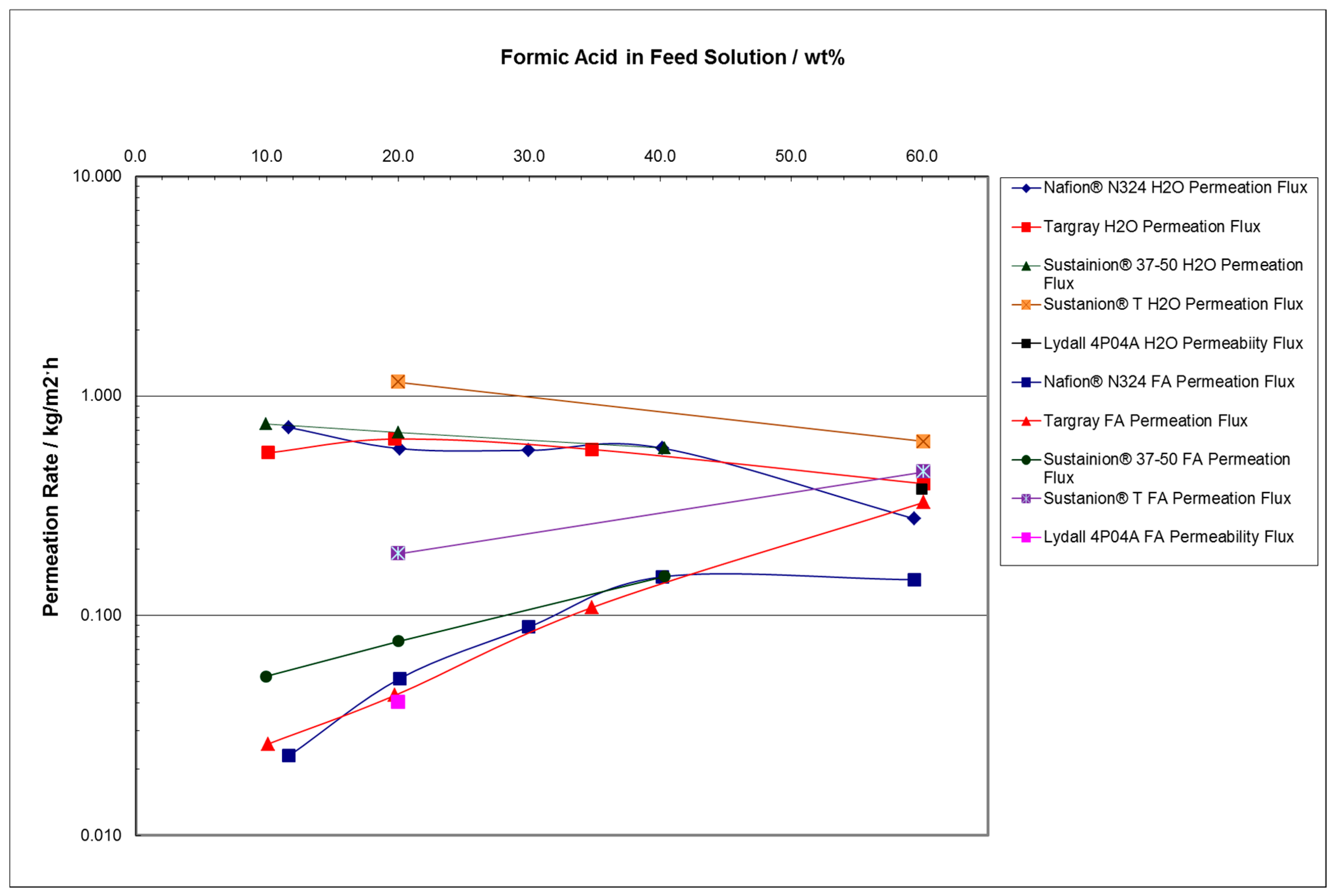
Table 4 summarizes the pervaporation data from Supplementary Materials Table S1 at a selected temperature of 60 °C for the various membranes and operating at various FA feed concentrations, ranging from 10 to 60 wt%. This higher temperature was chosen since the FA feed solutions could be easily heated to this temperature using heat exchangers in an azeotropic distillation system in addition to having higher permeation flux rates. Figure 3 shows a comparison plot of the data on a log scale. The H2O permeation mass flux rates remained reasonably constant with temperature for all the membranes up to a 40 wt% FA feed concentration. The corresponding FA permeation mass flux rates steadily increased with increasing feed FA wt%, approaching the H2O permeation flux rate at 60 °C. This shows that both temperature and FA concentrations are critically important operation factors to consider when optimizing a pervaporation membrane process for the FA-H2O binary system using these selected membranes. The Sustainion® anion membranes did not show any significant anion ion enhancement behavior in increasing the FA transport through the membrane. These results indicate that the pervaporation process separation efficiency with all these membranes is significantly less when operating at FA concentrations above about 40 wt% FA at a temperature of 60 °C.
Table 5 provides a summary of the H2O/FA mass flux ratio data from Supplementary Materials Table S1, and Figure 4 shows the data plotted graphically for the pervaporation system operation at 60 °C. The H2O/FA permeation flux ratio performance of Nafion® N324 was significantly better at 10 wt% FA, followed by a better performance of the Targray membrane at a 20 wt% FA feed concentration. At 30 wt% FA, all of the permeation mass flux ratios of H2O/FA show a significant decline. The mass flux ratios approach unity at FA concentrations approaching 60 wt% at 60 °C, indicating that equal amounts of water and FA are being passed through the membranes, i.e., an azeotropic composition. Thus, these experimental results indicate that a pervaporation separation process utilizing any of these selected membranes would only be suitable for concentrating FA to assays not exceeding about 30 wt% FA at these operating temperatures.
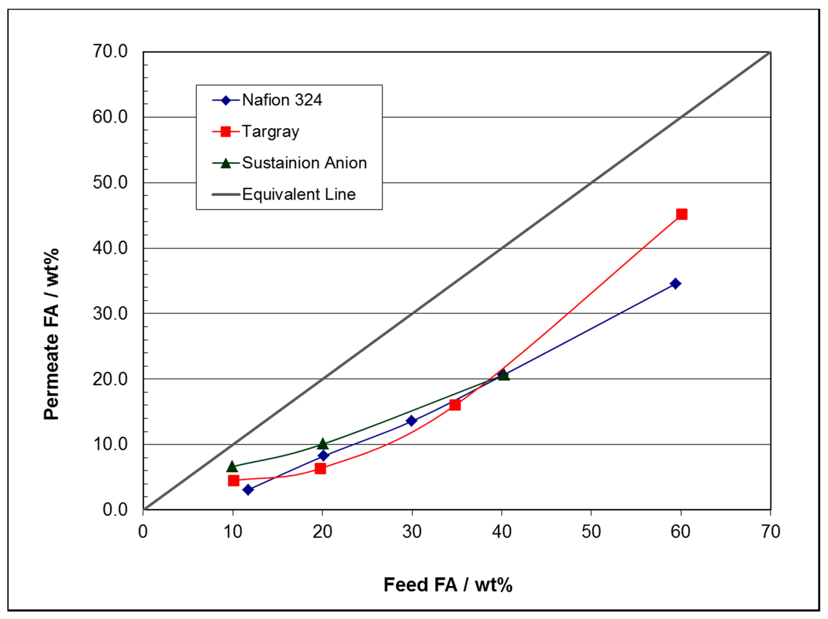
Figure 5 shows a different comparison plot of the wt% FA in the permeate versus the FA wt% in the feed for the Nafion® N324, Targray, and Sustainion® anion membranes at an operating temperature of 60 °C. The data shows that the FA wt% concentration in the permeate is steadily increasing with the corresponding wt% of FA present in the feed.
The reason for permeation separation reduction at higher wt% FA feed concentrations and at higher operating temperatures may be related to the VLE characteristics of the FA-H2O system at these temperature and pressures, especially for the microporous membranes. This is because the solutions are approaching the azeotropic composition at these temperatures. This is further discussed in Section 3.4.

3.2. FA Extended Time Batch Pervaporation Experimental Run Results

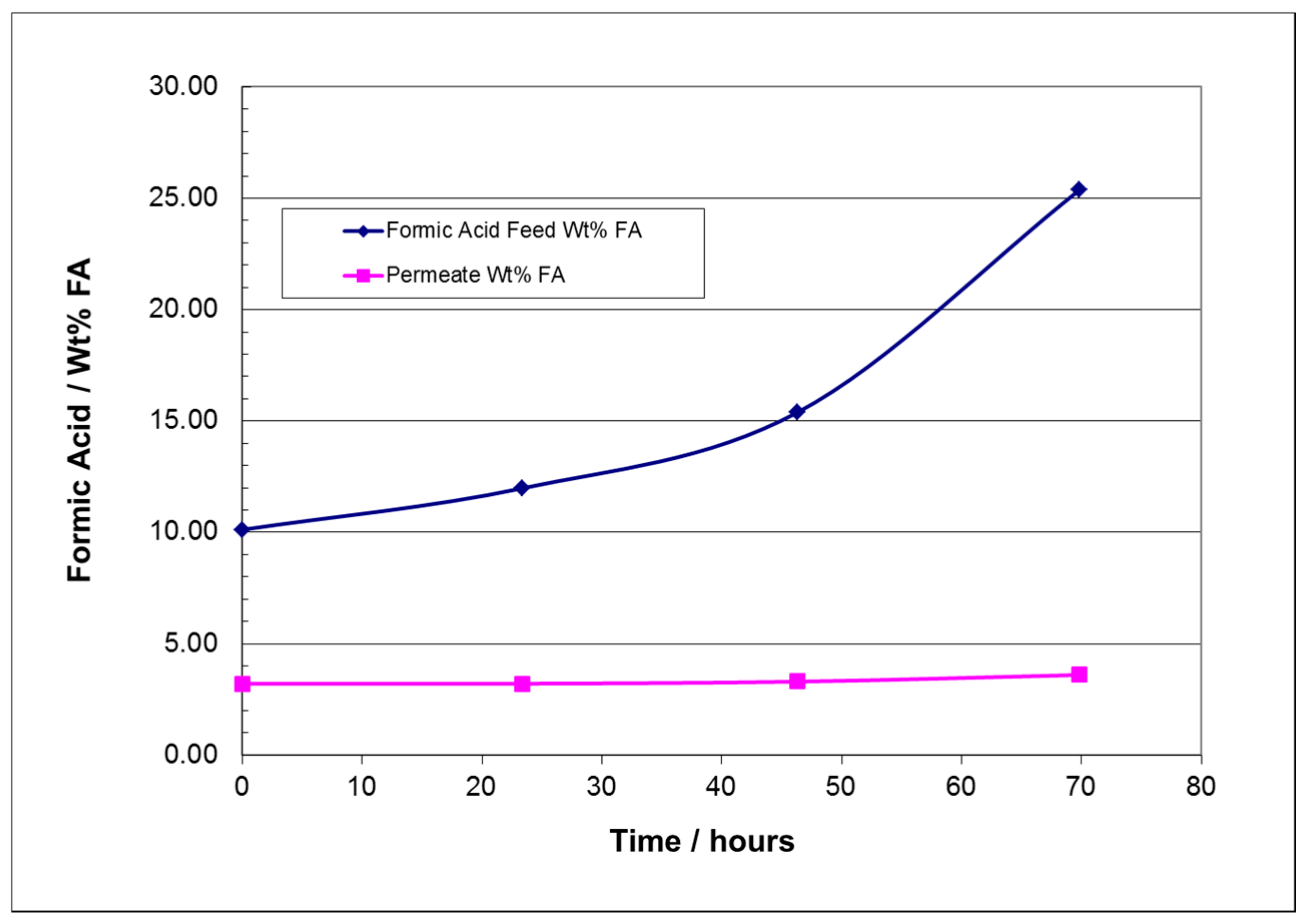
An extended time pervaporation batch run was conducted using the Targray SD425101 membrane. The initial solution feed weight was 200 g, with a starting concentration of 10.12 wt% FA. The feed solution temperature was maintained at 40 ± 1 °C. The formic acid feed was recirculated continuously through the permeation cell feed compartment. The permeate vapor was condensed and collected in the glass flask condenser which was immersed in an ice water bath. The air pump recirculated air in the permeate recirculation loop at a rate of 2 L/min. The permeate was periodically collected and weighed, taking a small 0.5 g sample of the feed solution about every 23 h for FA wt% analysis. Table 6 shows the tabulated test results and Figure 6 shows the results graphically.
The FA concentration in the feed increased from an initial 10.12 wt% to a final concentration of 25.38 wt%. The total permeate mass collected was 135.70 g, with an FA composite concentration of 3.69 wt%. A total of 4.68 g of FA (100% basis) had transferred through the membrane into the permeate from the starting FA feed solution, which contained an initial total of 20.24 g of FA. So about 23.1% of the FA had transferred though the membrane with the water.
The FA in the permeate would need to be recovered, which could be done using a second pervaporation module operating under different temperature conditions with a recycle back to the electrochemical FA cell. Additional data on the pervaporation performance at lower wt% FA concentrations would need to be conducted to determine the best operating temperatures. The other alternative is in finding membranes with better pervaporation separation characteristics for the FA-H2O system.

3.3. FA Pervaporation Batch Calculations

The experimental data generated was combined with some engineering calculations to determine the usefulness of the pervaporation method in concentrating FA solutions. The experimental data results showed the following:
  • At FA feed concentrations of 10 to 25 wt%, the water permeation mass flux rate was found to be relatively constant for most of the membrane separator materials, around 0.78 kg/m2 h for H2O and a much lower mass permeation flux rate for FA at 0.026 kg/m2 h for temperatures in the 22 to 60 °C range.
  • At 30 to 60 wt% FA feed concentrations, the water permeation mass flux rate is lower, and the FA permeation mass flux rate increases to about 0.10 kg/m2 h for FA feed concentrations above 30 wt%.
Supplementary Materials Table S2 shows a simple engineering calculation summary example in conducting a batch permeation run starting with 1.0 ton of 10 wt% FA feed solution, with the system simulating the use of a 100 m2 area Targray SD425101 membrane pervaporation cell module, and operating for a 9.5 h period at a temperature of about 40 °C. The assumed constant permeation mass flux rates in kg/m2 h for the Targray membrane were 0.012 for FA and 0.60 for H2O. The final feed solution result showed an increase of the FA concentration to 32.2%, and the final permeate concentration was a dilute 3.23 wt% FA solution. The total formic acid transport to the permeate side was calculated to be 24.7 kg out of the original 100 kg of FA in the feed (i.e., 24.7% transport of the FA to the permeate side). In a commercial process, the dilute FA permeate solution would be partially recycled as a feed to the electrochemical FA cell. Supplementary Materials Figure S5 shows a graphical plot of the data in Supplementary Materials Table S2. The calculated results are in line with the extended experimental run results in Section 3.2. The calculated energy consumption for pervaporation at these conditions, including a centrifugal pump (1200 L/min, at 15 hp), air blower (80,000 L/min, at 2 hp), and refrigeration cooling (32 kW, 9 tons) was estimated to be no more than about $25/metric ton (MT) FA (100% FA basis) using a power cost of $0.05/kWh.

3.4. Energy Steam Cost Estimates for Concentrating FA in an Azeotropic Distillation Tower

The wt% FA feed concentration is the important factor in determining the energy process costs for the azeotropic distillation of the electrochemically produced FA to a commercial concentration product. In this cost estimate example, an 85 wt% FA product solution was chosen. The simplified one-column pressure azeotropic distillation ChemCad simulation runs are detailed in Section S2 of the Supplementary Materials.
Table 7 shows the calculated total steam costs for the starting FA feed solution concentrations, ranging from 5 to 30 wt% FA and using steam costs of $8 and $10/million (MM) Btu (1 MM Btu = 293 kWh = 1055 MJ). Increasing the FA feed concentration to about 30 wt% FA using pervaporation would significantly reduce the steam cost in the operation for the azeotropic distillation column to about $107/MT of FA versus $292/MT for a 10 wt% FA feed solution at a steam cost of $8/MM Btu. Figure 7 shows the results graphically. This is a simplified energy cost analysis to show the relative impact of FA feed concentration on distillation costs. A more rigorous analysis would look at additional heat exchangers and potentially look at combining both a vacuum and pressure distillation units to minimize overall steam energy costs. In comparison, the calculated energy consumption for pervaporation starting with a 10 wt% FA feed solution and producing a 30 wt% FA product operating under the conditions as given in Section 3.3 is estimated to cost no more than $25/MT of FA based on the hp required for the pump and blower.

3.5. Examination of Formic Acid and Water Vapor Pressure and VLE Properties in View of the Membrane Pervaporation Results

In order to further interpret the results of the various membranes in the permeation results, pure vapor data of FA, water, as well as the FA-H2O system VLE data generated from ChemCad were generated and examined. FA is known to deviate from an ideal gas, and part of the reason is that FA molecules dimerize in the vapor phases. At room temperature, 95% of the formic acid vapor consists of the dimer [17]. In the solution phase, FA is a weak acid that is only partially dissociated or ionized. For example, a 1 M FA solution is calculated to only be about 1.4% dissociated using the literature acid dissociation constant Ka value of 1.77 × 10⁻⁴. The passage of FA and water through all of the selected membranes into the permeate all seem to be related to the VLE characteristics of the FA-H2O binary system.
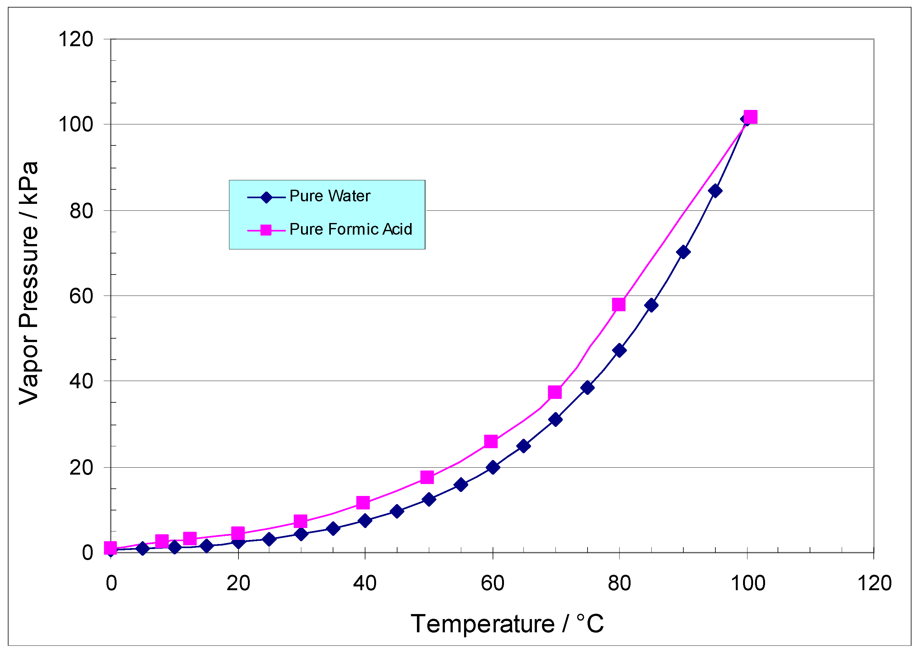
A plot of the vapor pressure of pure FA [17] and pure water [40] versus temperature is shown in Figure 8. Here, the vapor pressure of pure FA is shown to be significantly higher than that of pure water throughout the temperature range of 0–100 °C, but this is not the case for the FA-H2O solution mixtures when we look at the actual VLE data. In the VLE data, more water is present in the vapor phase than the FA at the lower FA concentrations below the azeotrope.
The interaction of FA with water in both the liquid and gas phases dramatically affects the VLE of the FA-H2O mixture due to hydrogen bonding between the two molecules. ChemCad was used to calculate a number of the FA solution and vapor compositions at selected constant temperatures (Txy). The Txy plots for the FA-H2O system are provided in the Supplementary Materials in Section S3, Figures S11–S20. The constant temperatures chosen were 22, 40, 60, 80, and 100 °C.
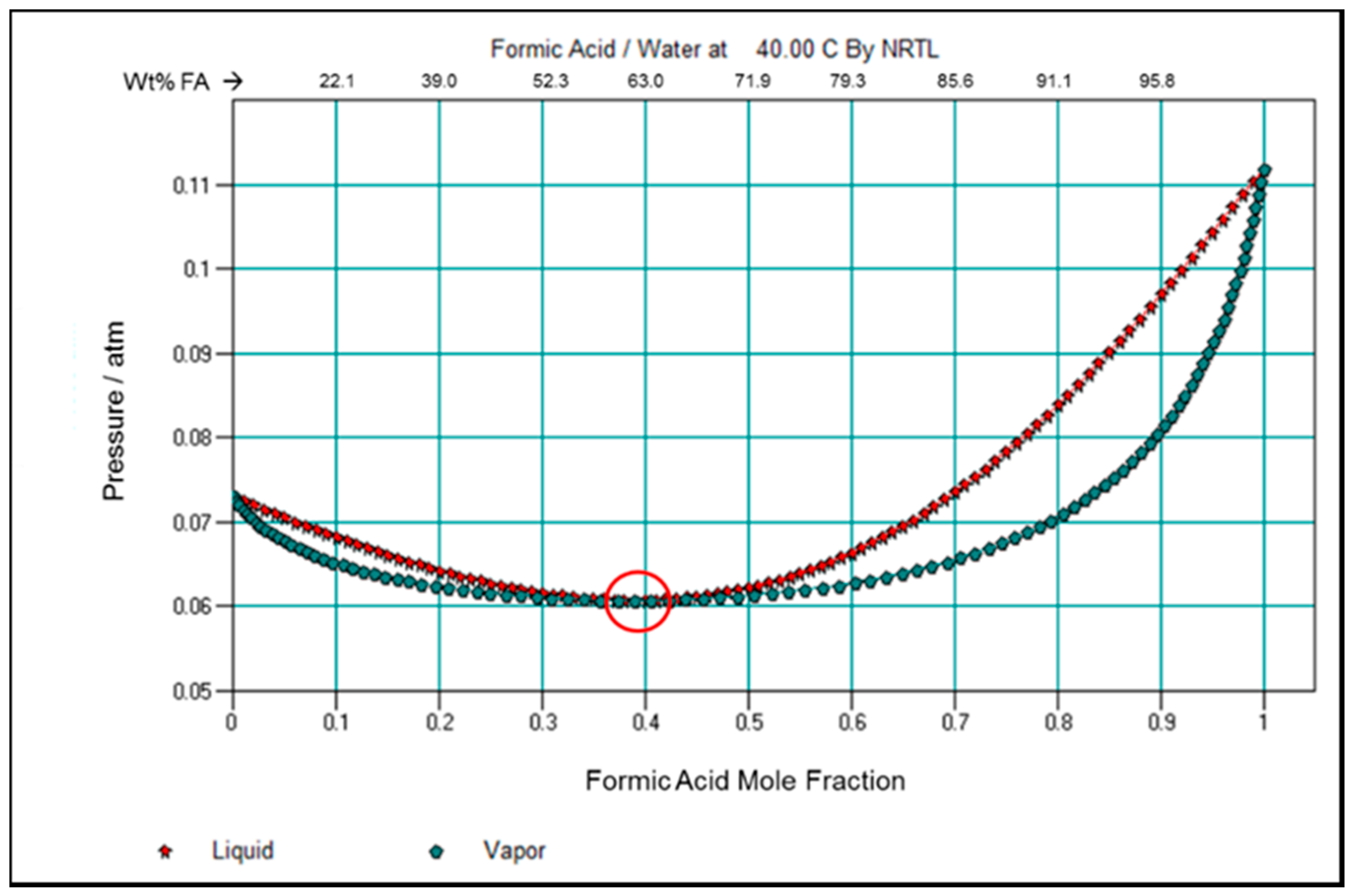
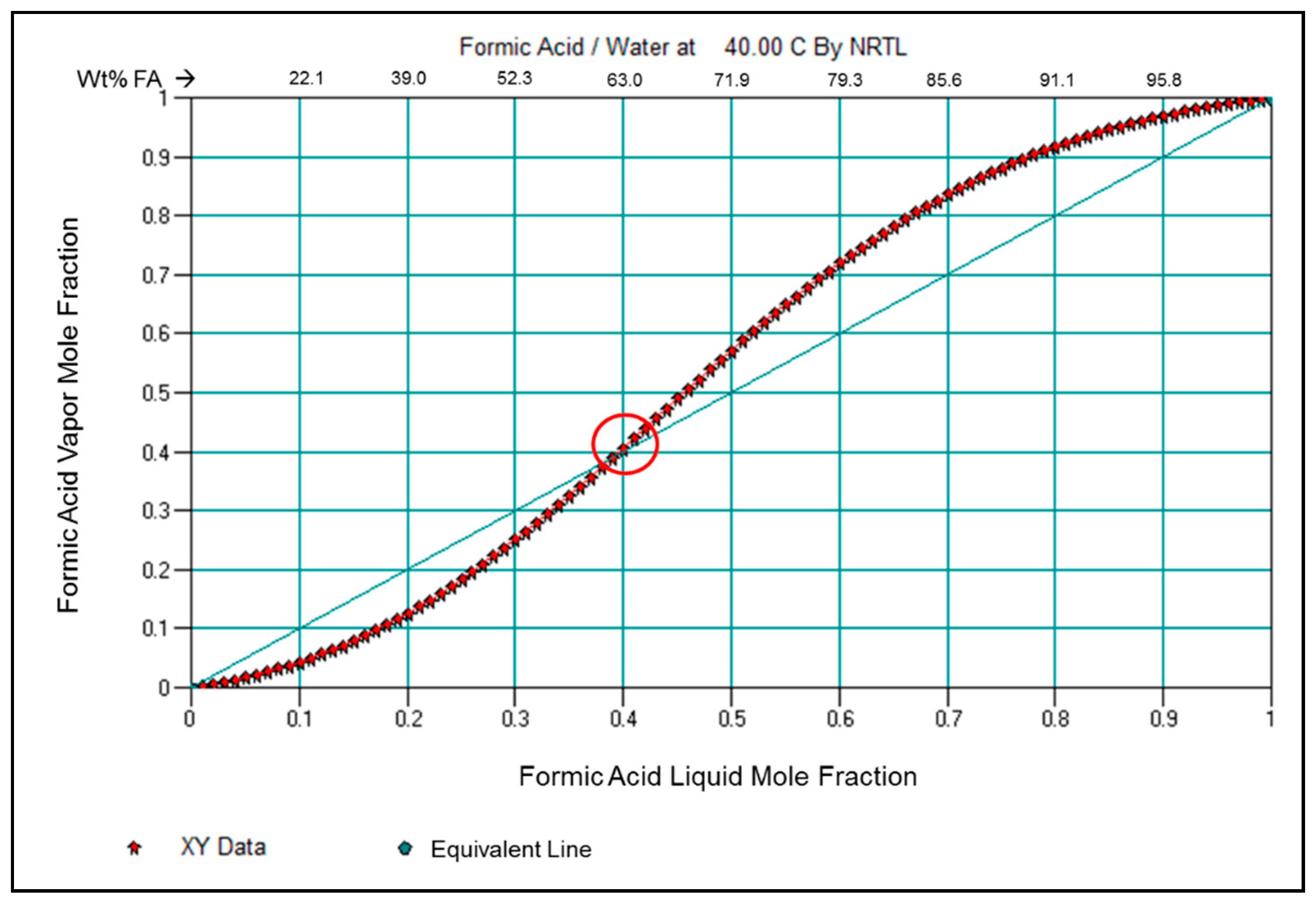
In examining the FA-H2O system at a constant temperature of 40 °C, Figure 9 shows the ChemCad data-generated constant temperature Txy plot on the formic acid mole fraction changes in the liquid and vapor phases versus pressure. The formic acid mole fraction with water in the vapor phase is less than that in the solution phase until it approaches the minimum azeotropic concentration. The red circle shows the minimum pressure azeotrope composition. Figure 10 shows the data plotted as FA molar vapor fraction versus the molar FA liquid fraction. The corresponding FA wt% concentrations are shown at the top axis of the graphs.
Figure 9 and Figure 10 show that the formic acid vapor and liquid compositions converge to the azeotropic composition (circled) at approximately a 0.4 molar fraction liquid FA, or about 63 wt% FA solution composition. The vapor molar content of the FA component is lower than that of the solution phase at lower FA solution concentrations, allowing for potentially more water transport through the membranes than FA, i.e., higher H2O/FA permeation flux rates. There may be some additional permeation selectivity occurring due to the interaction of the membranes with the FA dimer and water in both the microporous- and polymeric-based ion exchange membranes.
The ChemCad simulation results correspond with the membrane pervaporation experimental results, wherein the H2O/FA mass flux permeation ratios all decline to near 1:1 ratio with increasing wt% FA concentrations as they approach the azeotropic composition, as seen in Figure 4.
Figure 6 shows that the Nafion® N324 cation ion exchange membrane had a 2.1 H2O/FA mass flux selectivity ratio for water over FA at the higher FA concentrations, having a permeate with a 34 wt% FA concentration versus the feed being 60 wt% FA. The Targray membrane at similar conditions had a higher permeate concentration of 45 wt% FA. The performance of cation exchange membranes, particularly less expensive hydrocarbon types, such as the Neosepta® CSE or CMB (Astom Corp., Tokyo, Japan) and CMI-7000 by Membranes International (Ringwood, NJ, USA) as examples, may be able to perform at higher selectivities operating at higher wt% FA concentrations above the azeotropic composition.
The search and evaluation of more water selective membrane compositions is one area that needs to be investigated in future work. These experimental studies should include membranes comprising polyvinyl alcohol (PVA) and polydimethylsiloxane (PDMS) in potentially increasing water flux permeability versus FA. Alternatively, membranes having functional amine groups that may interact with FA, potentially slowing its passage through the membrane, should also be investigated.

3.6. Conceptual Systems Employing Pervaporation in Concentrating FA

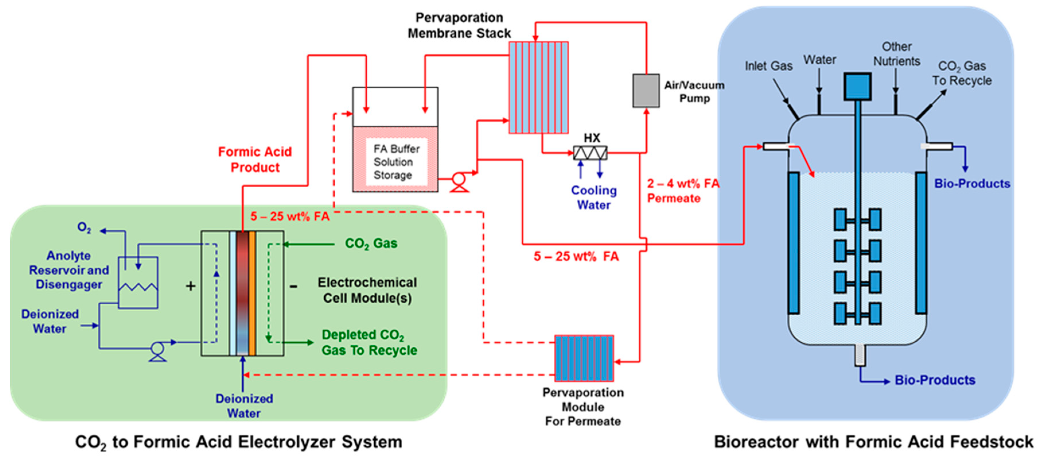
Figure 11 shows a conceptual process for integrating both the FA electrochemical cell and pervaporation units into a low-cost, on-site system for supplying FA as a feedstock to a bioreactor system. The electrochemical FA cell would convert the CO2 generated from the bioreactor into an FA product that would be concentrated to a 10 to 40 wt% FA concentration using the low energy-consuming pervaporation units. The dilute FA in the permeation system permeate would be recycled back to the FA cell, being used in place of the DI water. The expense of shipping concentrated FA from manufacturing locations would be eliminated.
Figure S6 in the Supplementary Materials shows a similar conceptual system in producing a commercial FA solution product with the addition of one or more azeotropic distillation columns. Increasing the FA concentration from the electrochemical FA cell to the azeotropic distillation unit(s) would significantly reduce steam costs for the system operation, as given in Table 7.

4. Summary

A new electrochemical process capable of generating a 5–25 wt% pure formic acid (FA) from the electrochemical reduction of CO2 requires a low-energy process for producing a more concentrated FA product for use in both on-site and commercial use applications. Pervaporation was identified as a potential low-energy method to evaluate in concentrating the FA product solution. To our knowledge, no literature has been found investigating the application of pervaporation for the FA-H2O binary system.
In order to evaluate this, a 25 cm2 membrane area pervaporation test cell was constructed to evaluate the FA-H2O system separation performance of three distinct types of membrane candidates at various FA feed concentrations and temperatures. The selection included one cation ion exchange, two anion ion exchanges, and two microporous hydrophobic membranes.
The permeation flux rates of FA and H2O were measured at FA feed concentrations of 10, 20, 40, and 60 wt% and at temperatures of 22, 40, and 60 °C respectively, for time periods ranging from 1.5 to 24 h. The experimental permeability separation factor (α) for these membranes and separators ranged from about 1.5 to 4. The H2O/FA flux ratio of all the membranes showed a decreasing trend towards 1.0 when the FA feed concentration approached a 60% FA feed concentration, which turns out to be near the azeotropic composition of 63 wt% in the FA-H2O system at these temperatures. The selected cation and anion ion exchange membranes did not show any significant enhancements in blocking or promoting the transport of the formate ion or FA through the membranes. The pervaporation separation results all followed the VLE liquid and vapor characteristics of the FA-H2O system, where the FA molar vapor composition changes with the FA feed composition.
An extended pervaporation run (about 69 h) at 40 °C using a 10.12 wt% FA feed solution and a Targray membrane demonstrated that the FA solution could be concentrated to a 25.38 wt% FA product. A Targray microporous HDPE membrane and a Chemours Nafion® N324 membrane showed the best permeation selectivities and flux rates. The Targray membrane showed kg/m2 h permeation flux rates of 0.60 for H2O and 0.012 for FA at a feed concentration of 10 wt% FA at 40 °C.
The experimental results indicate that pervaporation should be a good fit for concentrating the FA solution product to concentrations of about 30 wt% FA at operating temperatures of 60 °C or less. The pervaporation membrane separation performance declined significantly above that concentration.
Azeotropic distillation simulations for the FA-H2O system using ChemCad 6.0 were used to determine the energy requirement using steam costs in processing FA feed concentrations ranging from 5 to 30 wt%. The calculations showed substantial energy savings using higher FA concentrations if produced using pervaporation. Lowering the energy cost for the evaporation/concentration of the FA product would help in achieving an economically sustainable formic acid process from CO2 utilizing available renewable energy sources.
Future work should concentrate on evaluating more water selective membrane compositions. In addition, membranes having functional amine groups may potentially interact with FA and retard the passage of FA through the membrane into the permeate.

Supplementary Materials

The following are available online at https://www.mdpi.com/2311-5629/6/2/42/s1, Figure S1: Experimental FA-H2O pervaporation test system arrangement. Figure S2: Experimental pervaporation cell configuration schematic—side view. Figure S3: The 25 cm2 pervaporation cell assembled outside view shown in (a). The pervaporation cell internal view is shown in (b), showing one of the membranes (Targray) being positioned in the cell for testing. Figure S4: Photos of the various microporous and ion exchange membranes tabulated in Table 1. The membranes are: (a) Targray SD425101, (b) Nafion® N324, (c) Lydall Solupor® 4PO4A, (d) Sustainion® 37-50 anion exchange membrane, and (e) Sustainion® 37-50 T ePTFE reinforced anion exchange membrane. Figure S5: Theoretical calculated concentration change in the FA feed solution and permeate in a batch permeation run starting with a 10 wt% FA feed solution. Assumptions were for a 100 m2 permeation membrane area stack, operation for a 9.5 h period at a temperature of about 40 °C, and constant permeation mass flux rates of water and FA of 0.78 kg/m2 h and 0.028 kg/m2 h respectively. Figure S6: Conceptual system using the electrochemical FA cell integrated with pervaporation units and a single high pressure azeotropic distillation unit to produce commercial concentrations of FA. Figure S7: CHEMCAD 6.01 azeotropic distillation simulation modeling of the FA-water system at a pressure of 110 kPA maximizing the formic acid product concentration and minimizing FA in the overhead water product. The FA product output stream was 66.9 wt% at these conditions, not reaching the expected 77.5 wt% at these simulation conditions. Figure S8: CHEMCAD 6.01 azeotropic distillation simulation modeling of the FA-water system at a pressure of 220.6 kPA maximizing the formic acid product concentration and minimizing FA in the overhead water product. The FA product output stream was 80.6 wt% at these conditions. Figure S9: CHEMCAD 6.01 azeotropic distillation simulation modeling of the FA-water system at a pressure of 330.9 kPA maximizing the formic acid product concentration and minimizing FA in the overhead water product. The FA product output stream was 85.8 wt% at these conditions. Figure S10: ChemCad 6.01 azeotropic distillation simulation modeling of the FA-water system at a pressure of 330.9 kPA maximizing the formic acid product concentration and minimizing FA in the overhead water product. The modeling had the addition of a heat exchanger to preheat the FA solution feed from the overhead water product stream. Figure S11: Formic acid-water Txy vapor equilibrium plot at a constant temperature of 22 °C generated using ChemCad generated NRTL data. The circle shows the pressure-minimum azeotrope composition. Figure S12: Formic acid-water Txy vapor equilibrium plot at a constant temperature of 22 °C generated using ChemCad generated NRTL data. The circle shows the azeotrope composition at that temperature. Figure S13: Formic acid-water vapor Txy equilibrium plot at a constant temperature of 40 °C generated using ChemCad generated NRTL data. The circle shows the pressure-minimum azeotrope composition. Figure S14: Formic acid-water vapor Txy equilibrium plot at a constant temperature of 40 °C generated using ChemCad generated NRTL data. The circle shows the azeotrope composition at those conditions. Figure S15: Formic acid-water Txy vapor equilibrium plot at a constant temperature of 60 °C generated using ChemCad generated NRTL data. The circle shows the pressure-minimum azeotrope composition. Figure S16: Formic acid-water Txy vapor equilibrium plot at a constant temperature of 60 °C generated using ChemCad generated NRTL data. The circle shows the azeotrope composition at those conditions. Figure S17: Formic acid-water Txy vapor equilibrium plot at a constant temperature of 80 °C generated using ChemCad generated NRTL data. The circle shows the pressure-minimum azeotrope composition. Figure S18: Formic acid-water Txy vapor equilibrium plot at a constant temperature of 80 °C generated using ChemCad generated NRTL data. The circle shows the azeotrope composition at those conditions. Figure S19: Formic acid-water vapor Txy equilibrium plot at a constant temperature of 100 °C generated using ChemCad generated NRTL data. The circle shows the pressure-minimum azeotrope composition. Figure S20: Formic acid-water Txy vapor equilibrium plot at a constant temperature of 100 °C generated using ChemCad generated NRTL data. The circle shows the azeotrope composition at those conditions. Table S1: Summary table of all the pervaporation experimental data. Table S2: Batch permeation calculation for a starting 1 tonne 10 wt% FA feed solution using a 100 m2 Targray membrane area pervaporation cell module, and operation for a 9.5 h period at a temperature of about 40 °C to produce a 32.1 wt% FA product concentration. Table S3: Azeotropic formic acid-water composition and boiling point (BP) as a function of pressure (in bar) from reference [5]. Table S4: Summary of the Azeotropic distillation simulation column overhead and bottoms FA and H2O wt% composition.

Author Contributions

J.J.K. conceived the project and conducted a set of experiments at Dioxide Materials in tandem with P.S.L., who supervised the experimental work conducted by L.J.M. at Georgian Court University. J.J.K., P.S.L., and L.J.M. all contributed in the writing and editing of this article. All authors have read and agreed to the published version of the manuscript.

Funding

The experimental work was not funded by any U.S. government agency. The opinions here are those of the authors and may not reflect the opinions of Dioxide Materials Inc. and Georgian Court University.

Conflicts of Interest

P.S.L. and L.J.M. both have no conflicts or financial stake in this work or the results. J.J.K., as an employee of Dioxide Materials Inc., has a financial interest in the Sustainion® anion exchange membranes and in the electrochemical formic acid process. The Sustainion membranes are currently sold and marketed by Dioxide Materials to outside research groups so that they may evaluate these in the development of electrochemical processes and other applications.

References

  1. Aresta, M.; Dibenedetto, A. Utilisation of CO2 as a chemical feedstock: Opportunities and challenges. Dalton Trans. 2007, 28, 2975–2992. [Google Scholar] [CrossRef] [PubMed]
  2. Bocchini, S.; Castro, C.; Cocuzza, M.; Ferrero, S.; Latini, G.; Martis, A.; Pirri, F.; Scaltrito, L.; Rocca, V.; Verga, F.; et al. The virtuous CO2 circle or the three Cs: Capture, cache, and convert. J. Nanomater. 2017, 2017, 6594151. [Google Scholar] [CrossRef] [Green Version]
  3. Quadrelli, E.A.; Centi, G.; Duplan, J.-L.; Perathoner, S. Carbon Dioxide Recycling: Emerging Large-Scale Technologies with Industrial Potential. ChemSusChem 2011, 4, 1194–1215. [Google Scholar] [CrossRef] [PubMed]
  4. Masel, R.; Ni, R.; Liu, Z.; Chen, Q.; Kutz, R.; Nereng, L.; Lutz, D.; Lewinski, K. Unlocking the Potential of CO2 Conversion to Fuels and Chemicals as an Economically Viable Route to CCR. Energy Procedia 2014, 63, 7959–7962. [Google Scholar] [CrossRef] [Green Version]
  5. Masel, R.; Liu, Z.; Zhao, D.; Chen, Q.; Lutz, D.; Nereng, L. CO2 Conversion to Chemicals with Emphasis on using Renewable Energy/Resources to Drive the Conversion. In Commercializing Biobased Products: Opportunities, Challenges, Benefits, and Risks; The Royal Society of Chemistry: London, UK, 2016; Chapter 10; pp. 215–257. [Google Scholar]
  6. Jhong, H.-R.M.; Ma, S.; Kenis, P.J.A. Electrochemical conversion of CO2 to useful chemicals: Current status, remaining challenges, and future opportunities. Curr. Opin. Chem. Eng. 2013, 2, 191–199. [Google Scholar] [CrossRef]
  7. Hu, B.; Guild, C.; Suib, S.L. Thermal, electrochemical, and photochemical conversion of CO2 to fuels and value-added products. J. CO2 Util. 2013, 1, 18–27. [Google Scholar] [CrossRef]
  8. Aresta, M.; Dibenedetto, A.; Quaranta, E. State of the art and perspectives in catalytic processes for CO2 conversion into chemicals and fuels: The distinctive contribution of chemical catalysis and biotechnology. J. Catal. 2016, 343, 2–45. [Google Scholar] [CrossRef]
  9. Peters, M.; Köhler, B.; Kuckshinrichs, W.; Leitner, W.; Markewitz, P.; Müller, T.E. Chemical Technologies for Exploiting and Recycling Carbon Dioxide into the Value Chain. ChemSusChem 2011, 4, 1216–1240. [Google Scholar] [CrossRef]
  10. Halmann, M.M. Chemical Fixation of Carbon Dioxide: Methods for Recycling CO2 Into Useful Products; CRC Press: London, UK, 1993; pp. 67–127. [Google Scholar]
  11. Yang, H.; Kaczur, J.J.; Sajjad, S.D.; Masel, R.I. Electrochemical conversion of CO2 to formic acid utilizing Sustainion™ membranes. J. CO2 Util. 2017, 20, 208–217. [Google Scholar] [CrossRef]
  12. Yang, H.; Kaczur, J.J.; Sajjad, S.D.; Masel, R.I. CO2 Conversion to Formic Acid in a Three Compartment Cell with Sustainion™ Membranes. ECS Trans. 2017, 77, 1425–1431. [Google Scholar] [CrossRef]
  13. Kaczur, J.J.; Yang, H.; Liu, Z.; Sajjad, S.D.; Masel, R.I. Carbon dioxide and water electrolysis using new alkaline stable anion membranes. Front. Chem. 2018, 6, 263. [Google Scholar] [CrossRef] [PubMed] [Green Version]
  14. Kaczur, J.J.; Yang, H.; Sajjad, S.D.; Masel, R.I. Method and System for Electrochemical Production of Formic Acid from Carbon Dioxide. U.S. Patent 10,047,446, 14 August 2018. [Google Scholar]
  15. Kutz, R.B.; Chen, Q.; Yang, H.; Sajjad, S.D.; Liu, Z.; Masel, I.R. Sustainion Imidazolium-Functionalized Polymers for Carbon Dioxide Electrolysis. Energy Technol. 2017, 5, 929–936. [Google Scholar] [CrossRef] [Green Version]
  16. Pérez-Fortes, M.; Schöneberger, J.C.; Boulamanti, A.; Harrison, G.; Tzimas, E. Formic acid synthesis using CO2 as raw material: Techno-economic and environmental evaluation and market potential. Int. J. Hydrog. Energy 2016, 41, 16444–16462. [Google Scholar] [CrossRef]
  17. Hietala, J.; Vuori, A.; Johnsson, P.; Pollari, I.; Reutemann, W.; Kieczka, H. Formic Acid. In Ullmann’s Encyclopedia of Industrial Chemistry; Wiley: Hoboken, NJ, USA, 2016; pp. 1–22. [Google Scholar]
  18. Feng, X.; Huang, R.Y.M. Liquid separation by membrane pervaporation:  A review. Ind. Eng. Chem. Res. 1997, 36, 1048–1066. [Google Scholar] [CrossRef]
  19. Chopade, S.P.; Mahajani, S.M. Pervaporation: Membrane Separations. In Encyclopedia of Separation Science; Wilson, I.D., Ed.; Academic Press: Oxford, UK, 2000; pp. 3636–3641. [Google Scholar]
  20. Kujawski, W. Application of pervaporation and vapor permeation in the environmental protection. Pol. J. Environ. Stud. 2000, 9, 13–26. [Google Scholar]
  21. Jyoti, G.; Keshav, A.; Anandkumar, J. Review on Pervaporation: Theory, Membrane Performance, and Application to Intensification of Esterification Reaction. J. Eng. 2015, 2015, 927068. [Google Scholar] [CrossRef] [Green Version]
  22. Hilmen, E.-K. Separation of Azeotropic Mixtures: Tools for Analysis and Studies on Batch Distillation Operation. Ph.D. Thesis, Norwegian University of Science and Technology, Department of Chemical Engineering , Trondheim, Norway, 2000. [Google Scholar]
  23. Shao, P.; Huang, R.Y.M. Polymeric membrane pervaporation. J. Membr. Sci. 2007, 287, 162–179. [Google Scholar] [CrossRef]
  24. Wang, Y.; Widjojo, N.; Sukitpaneenit, P.; Chung, T.-S. Membrane Pervaporation. In Separation and Purification Technologies in Biorefineries; John Wiley & Sons: Hoboken, NJ, USA, 2013; pp. 259–299. [Google Scholar]
  25. Qin, Y.; Sheth, J.P. Pervaporation membranes that are highly selective for acetic acid over water. Ind. Eng. Chem. Res. 2003, 42, 582–595. [Google Scholar] [CrossRef]
  26. Li, G.; Kikuchi, E.; Matsukata, M. A study on the pervaporation of water–acetic acid mixtures through ZSM-5 zeolite membranes. J. Membr. Sci. 2003, 218, 185–194. [Google Scholar] [CrossRef]
  27. Işıklan, N.; Şanlı, O. Separation characteristics of acetic acid–water mixtures by pervaporation using poly(vinyl alcohol) membranes modified with malic acid. Chem. Eng. Process. Process. Intensif. 2005, 44, 1019–1027. [Google Scholar] [CrossRef]
  28. Dave, H.K.; Nath, K. Effect of Temperature on Pervaporation Dehydration of Water-Acetic Acid Binary Mixture; NISCAIR-CSIR: Delhi, India, 2017. [Google Scholar]
  29. Dibenedetto, A.; Aresta, M.; Angelini, A.; Ethiraj, J.; Aresta, B.M. Synthesis, Characterization, and Use of NbV/CeIV-Mixed Oxides in the Direct Carboxylation of Ethanol by using Pervaporation Membranes for Water Removal. Chem. Eur. J. 2012, 18, 10324–10334. [Google Scholar] [CrossRef] [PubMed]
  30. Mulder, M.H.V.; Hendrickman, J.O.; Hegeman, H.; Smolders, C.A. Ethanol—Water separation by pervaporation. J. Membr. Sci. 1983, 16, 269–284. [Google Scholar] [CrossRef] [Green Version]
  31. Fouad, E.A.; Feng, X. Use of pervaporation to separate butanol from dilute aqueous solutions: Effects of operating conditions and concentration polarization. J. Membr. Sci. 2008, 323, 428–435. [Google Scholar] [CrossRef]
  32. Huang, S.-C.; Ball, I.J.; Kaner, R.B. Polyaniline membranes for pervaporation of carboxylic acids and water. Macromolecules 1998, 31, 5456–5464. [Google Scholar] [CrossRef]
  33. Akbar, S.; Punnathanam, S.; Pulkala, M. Adsorption of Aqueous Solutions of Carboxylic Acids on Montmorillonite, Silicalite, H-ZSM-5 and their Na+ - and Li+ - Exchanged Forms. J. Chem. Soc. Pak. 2008, 30, 664–673. [Google Scholar]
  34. Huang, R.Y.M. Novel Membrane Method. U.S. Patent 4,892,661, 9 January 1990. [Google Scholar]
  35. Yishai, O.; Lindner, S.N.; Gonzalez de la Cruz, J.; Tenenboim, H.; Bar-Even, A. The formate bio-economy. Curr. Opin. Chem. Biol. 2016, 35, 1–9. [Google Scholar] [CrossRef]
  36. Yishai, O.; Goldbach, L.; Tenenboim, H.; Lindner, S.N.; Bar-Even, A. Engineered Assimilation of Exogenous and Endogenous Formate in Escherichia coli. ACS Synth. Biol. 2017, 6, 1722–1731. [Google Scholar] [CrossRef] [Green Version]
  37. Bar-Even, A. Formate Assimilation: The Metabolic Architecture of Natural and Synthetic Pathways. Biochemistry 2016, 55, 3851–3863. [Google Scholar] [CrossRef]
  38. Bar-Even, A.; Noor, E.; Flamholz, A.; Milo, R. Design and analysis of metabolic pathways supporting formatotrophic growth for electricity-dependent cultivation of microbes. Biochim. Biophys. Acta (BBA) Bioenerg. 2013, 1827, 1039–1047. [Google Scholar] [CrossRef] [Green Version]
  39. Claassens, N.J.; Sánchez-Andrea, I.; Sousa, D.Z.; Bar-Even, A. Towards sustainable feedstocks: A guide to electron donors for microbial carbon fixation. Curr. Opin. Biotechnol. 2018, 50, 195–205. [Google Scholar] [CrossRef]
  40. Wexler, A. Vapor Pressure Formulation for Water in Range 0 to 100 °C. A Revision. J. Res. Natl. Bur. Stand. A Phys. Chem. 1976, 80, 775–785. [Google Scholar] [CrossRef] [PubMed]
Figure 1. Electrochemical formic acid (FA) cell system configuration in converting CO2 to a pure FA product [11,13,14]. The center compartment incorporates a strong acid cation ion exchange media that provides a higher ionic conductivity than the lower ionic conductivity FA solution product.
Carbon 06 00042 g001
Figure 2. Comparison plot of the permeation rates of H2O and FA for Nafion® N324 and Targray membranes using a 10 wt% FA feed solution at pervaporation system operating temperatures of 22, 40, and 60 °C.
Carbon 06 00042 g002
Figure 3. Comparison plot of the permeation rates of FA and H2O for the tested membranes in a range of 10 to 60 wt% FA solutions operating at a permeation system temperature of 60 °C.
Carbon 06 00042 g003
Figure 4. Graphical plot of the individual membrane H2O/FA mass permeation flux ratios as a function of the FA wt% concentration taken from the data in Table 5 at a permeation system operating temperature of 60 °C.
Carbon 06 00042 g004
Figure 5. Comparison plot of the wt% FA in the permeate versus the FA wt% in the feed for the Nafion® N324, Targray, and Sustainion® membranes at an operating temperature of 60 °C.
Carbon 06 00042 g005
Figure 6. Extended time batch pervaporation cell test run at 40 °C over a period of 69.84 h using a Targray SD425101 membrane, starting 10.12 wt% FA feed solution. The FA feed solution increased to about 25.38 wt% with a final composite permeate FA composite concentration of 3.49 wt%.
Carbon 06 00042 g006
Figure 7. Formic acid estimated steam cost per metric ton FA versus the input wt% FA feed concentration for a pressurized azeotropic distillation column at steam costs of $8 and $10 per MM Btu (1.055 MM kJ) steam.
Carbon 06 00042 g007
Figure 8. Comparison of pure FA and pure water component vapor pressures versus temperature.
Carbon 06 00042 g008
Figure 9. Formic acid-water vapor Txy equilibrium plot at a constant temperature of 40 °C generated using ChemCad-generated data using the non-random two-liquid (NRTL) model in generating the simulation data. The circle shows the pressure-minimum azeotrope composition.
Carbon 06 00042 g009
Figure 10. FA-water vapor Txy constant temperature equilibrium plot at a constant temperature of 40 °C generated using ChemCad-generated NRTL simulation data. The red circle shows the azeotropic composition at those conditions.
Carbon 06 00042 g010
Figure 11. Conceptual system using the electrochemical FA cell integrated using pervaporation units in supplying more concentrated FA solution on-site to a bioreactor in producing various chemicals and bio-products.
Carbon 06 00042 g011
Table 1. Membrane/microporous separator materials selected for formic acid (FA) pervaporation testing.
MembraneSourcePropertiesCost
Nafion® N324Ion Power
(New Castle, DE USA)
Fluoropolymer sulfonic acid-based cation ion exchange membraneExpensive per m2
($900–$1200)
Targray SD425101Targray
(Montreal, Quebec, Canada)
PE-based lithium battery separator, 45% open areaInexpensive per m2
($10–$30)
Sustainion® 37–50Dioxide Materials
(Boca Raton, FL, USA)
Styrene backbone, imidazole functionalized anion ion exchange membraneModerately expensive per m2
(Est. $20–$200) when fully commercialized
Sustainion® 37-50 TDioxide Materials
(Boca Raton, FL, USA)
Styrene backbone, imidazole functionalized anion ion exchange membrane with ePTFE supportModerately expensive per m2
(Est. $30–$300) when fully commercialized
Lydall Solupor® 4P04ALydall Performance Materials Inc. (Rochester, NH, USA)HDPE-based filtration membrane, 80% open areaInexpensive per m2
($10–$30)
Acronyms: PE: polyethylene, HDPE: High density polyethylene, ePTFE: Expanded polytetrafluoroethylene.
Table 2. Experimental pervaporation permeation flux data comparison between Nafion® N324 and Targray SD425101 membranes for both water and formic acid at a 10 wt% FA feed concentration.
MembraneTempFeed Composition (wt%)Permeate Composition (wt%)Permeability Separation Factor Permeation Flux or Rate of Water and FA through MembraneFlux Ratio
°CH2O (A)FA (B)H2O (A)FA (B)αab A/B * kg/m2ˑh kg/m2ˑh H2O/FA Ratio
Nafion® 3242290.789.2296.363.642.69H2O0.239FA0.00926.5
Nafion® 3244090.779.2396.743.263.02H2O0.463FA0.01629.7
Nafion® 3246088.3111.6996.93.104.14H2O0.719FA0.02331.3
Targray SD4251012289.0710.9395.864.142.84H2O0.215FA0.00923.2
Targray SD4251014089.7310.2796.143.862.85H2O0.801FA0.03224.9
Targray SD4251016089.9010.1095.494.512.38H2O0.552FA0.02621.2
Note: * Concentration A/B (wt%) in the permeate divided by the concentration A/B in the feed.
Table 3. Water and FA mass permeation flux ratios for Nafion® N324 and Targray SD425101.
MembraneTemperature °CH2O/FA Flux
Permeation Ratio
Nafion® N3242226.5
4029.7
6031.3
Targray SD4251012223.2
4024.9
6021.2
Note: 10 wt% FA Feed Solution.
Table 4. Pervaporation data summary (in a shorter tabulated form) for the various membranes at a fixed temperature of 60 °C and for FA feed concentrations ranging from 10 to 60 wt%.
MembraneTempFeed Composition (wt%)Permeate Composition (wt%)Perme-Ability Separation Factor Permeation Flux or Rate of Water and FA through Membrane
°CH2O (A)FA (B)H2O (A)FA (B)αab A/B * kg/m2ˑh kg/m2ˑh H2O/FA Ratio
Nafion® 3246088.311.796.93.14.14H2O0.719FA0.02331.3
Nafion® 3246079.920.291.88.32.81H2O0.576FA0.05211.1
Nafion® 3246070.030.086.413.62.72H2O0.566FA0.0896.4
Nafion® 3246059.940.279.420.62.58H2O0.579FA0.1503.9
Nafion® 3246040.659.465.434.62.77H2O0.276FA0.1461.9
Targray SD4251016089.910.195.54.52.38H2O0.552FA0.02621.2
Targray SD4251016080.219.893.66.43.62H2O0.637FA0.04314.7
Targray SD4251016065.234.884.016.02.80H2O0.571FA0.1095.2
Targray SD4251016039.960.154.945.11.83H2O0.399FA0.3281.2
Sustainion® 37-50 6090.19.993.46.61.55H2O0.745FA0.05314.1
Sustainion® 37-50 6080.020.189.910.12.24H2O0.683FA0.0778.9
Sustainion® 37-50 6059.740.379.320.72.59H2O0.578FA0.1513.8
Sustainion®
37-T ePTFE Reinforced
6080.020.185.814.21.51H2O1.155FA0.1916.0
Sustainion®
37-T ePTFE Reinforced
6039.960.157.942.12.07H2O0.620FA0.4511.4
Lydall Solupor® 4PO4A6080.020.190.39.72.33H2O0.376FA0.0409.3
Note: * Concentration A/B (wt%) in the permeate divided by the concentration A/B in the feed.
Table 5. Summary table of the membranes and calculated H2O/FA permeation mass flux ratios from Table 4.
Selected MembraneTemperature °CFeed wt% FAPermeate wt% FAH2O/FA Flux Ratio
Nafion® 3246011.73.131.3
Nafion® 3246020.28.311.1
Nafion® 3246030.013.66.4
Nafion® 3246040.220.63.9
Nafion® 3246059.434.61.9
Targray SD4251016010.14.521.2
Targray SD4251016019.86.414.7
Targray SD4251016034.816.05.2
Targray SD4251016060.145.11.2
Sustainion® 37-50 609.96.614.1
Sustainion® 37-50 6020.110.18.9
Sustainion® 37-50 6040.320.73.8
Sustainion® 37-50 T
ePTFE Reinforced
6020.114.26.0
Sustainion® 37-50 T
ePTFE Reinforced
6060.142.11.4
Lydall Solupor® 4PO4A6020.19.79.3
Table 6. Extended time batch permeation run using a Targray SD425101 membrane, starting with 200 g solution having a 10.12 wt% FA feed solution concentration, and operating the system for a total of 69.84 h at a temperature of 40 °C.
MembraneTempRun: Collection TimeFeed Composition (wt%)Permeate Composition (wt%)Permeation Flux or Rate of Water and FA through MembraneFlux Ratio
°CHoursH2O (A)FA (B)H2O (A)FA (B) kg/m2 h kg/m2 h H2O/FA Ratio
Targray SD4251014022.389.910.1296.83.21H2O0.771FA0.02630.2
Targray SD4251014045.388.011.9896.73.30H2O0.394FA0.01329.3
Targray SD4251014069.884.615.4096.43.60H2O0.265FA0.01026.8
Totals 69.874.625.3896.53.49H2O0.768FA0.02728.6
Table 7. Calculated steam cost for azeotropic distillation based on various FA wt% solution feedstocks per the conditions and configuration shown in Supplementary Materials Section S2 at steam values of $8 and $10 per MM Btu.
FeedFA/hBtu/hMM Btu/kg FAMM Btu/Tonne FA$10/MM Btu$8/MM Btu
wt% FAkg/hMM Btu Steam CostSteam Cost
54.910.380.07777.02$770$616
109.930.360.03736.56$366$292
1514.930.390.02625.86$259$207
2019.930.410.02120.52$205$164
2524.930.410.01616.27$163$130
3029.940.400.01313.31$133$107