Abstract
Cardiovascular prosthetic devices, stents, prosthetic valves, heart-assist pumps, etc., operate in a wide regime of flows characterized by fluid dynamic flow structures, laminar and turbulent flows, unsteady flow patterns, vortices, and other flow disturbances. These flow disturbances cause shear stress, hemolysis, platelet activation, thrombosis, and other types of blood trauma, leading to neointimal hyperplasia, neoatherosclerosis, pannus overgrowth, etc. Couette-type blood-shearing devices are used to simulate and then clinically measure blood trauma, after which the results can be used to assist in the design of the cardiovascular prosthetic devices. However, previous designs for such blood-shearing devices do not cover the whole range of flow shear, Reynolds numbers, and Taylor numbers characteristic of all types of implanted cardiovascular prosthetic devices, limiting the general applicability of clinical data obtained by tests using different blood-shearing devices. This paper presents the key fluid dynamic parameters that must be met. Based on this, Couette device geometric parameters such as diameter, gap, flow rate, shear stress, and temperature are carefully selected to ensure that the device’s Reynolds numbers, Taylor number, operating temperature, and shear stress in the gap fully represent the flow characteristics across the operating range of all types of cardiovascular prosthetic devices. The outcome is that the numerical data obtained from the presented device can be related to all such prosthetic devices and all flow conditions, making the results obtained with such shearing devices widely applicable across the field. Numerical simulations illustrate that the types of flow patterns generated in the blood-shearing device meet the above criteria.
Keywords:
hemolysis; blood shear; cardiovascular; prosthetic; device; vWF; Taylor; Reynolds; Couette 1. Introduction
Shear-induced blood trauma presents significant challenges across a range of medical prosthetic devices, including cardiovascular stents, heart valves, ventricular assist devices, and extracorporeal membrane oxygenation (ECMO) machines. Such trauma can lead to various adverse events, including platelet activation, hemolysis, and thrombosis. Achieving a quantitative understanding of how shear-induced blood trauma occurs is essential for enhancing the design of these medical prosthetic devices.
Commonly utilized shear devices include the annular Couette viscometer, cone and plate viscometer, and hybrid devices combining both principles [1]. However, these traditional shear devices are typically designed to operate within the laminar flow regime in order to ensure a uniform fluid shear stress field. This limitation means that they cannot fully capture the diverse operating conditions encountered in medical prosthetic devices, which include vortex flows and turbulence.
This article aims to address this gap by offering design considerations for developing a Couette device capable of simulating the operational range found across all cardiovascular prosthetic devices. By expanding the capabilities of experimental techniques to cover a broader range of flow conditions, researchers can gain deeper insights into shear-induced blood trauma and facilitate improvements in prosthetic device design.
2. Physiological Considerations
2.1. Non-Physiological Shear-Induced Blood Trauma in Stents
Stents are widely used in restoring blood flow for treating cardiovascular diseases such as coronary artery disease [2,3]. The insertion of a stent induces non-physiological flow both around the stented area [4,5,6] and downstream of the stented area [7], causing blood damage. Although the detailed distribution of the blood flow field varies with different designs, stent struts are usually discussed as a major design factor affecting the hemodynamic performance of stents [2,8,9,10,11,12,13,14]. The flow field around the stent struts is typically disturbed. This non-physiological flow favors hemolysis and thrombosis formation, neointimal hyperplasia, and neoatherosclerosis. These three symptoms often interact with each other [8,15] and can lead to embolization [7] and in-stent restenosis.
The recirculation zones around the edges of each stent strut are associated with low shear stress, and the flows on the top surface of each stent strut are associated with high shear stress [16,17]. High shear stress is associated with platelet activation and subsequent procoagulation effects [18,19]. Thrombosis events can cause subsequent neointimal hyperplasia [8,15]. Moreover, the low shear stress regions around the stent frames precipitate inflammation and facilitate neointimal hyperplasia [13,20]. The low shear stress and high shear stress regions in stents are usually separated by a middle range of 1.5 Pa to 2 Pa [2,5,19,21,22], which is the physiological wall shear stress. Platelet activation occurs in the magnitude of 1 Pa [1]. Low shear stress makes platelet adhesion easier and induces growth factors derived form both endothelial cells and platelets, which subsequently induce smooth muscle cell proliferation and migration [15]. Endothelial cells shift to a pro-atherogenic state under low shear stress [23], allowing them to express more inflammatory molecules [8,23]. Inflammatory cells are also reported to secrete growth factors to enhance neointima growth [13,20].
The proximal and distal areas of the stented region are influenced by the turbulence induced by the stent profile [19,24]. High shear stress in the turbulence region can also activate platelets and further add to the procoagulant state. Although the detailed mechanisms for the formation of stent thrombosis and neointimal hyperplasia are complicated and beyond the scope of this paper, non-physiological shear stress significantly affects these processes.
2.2. Non-Physiological Shear-Induced Blood Trauma in Valves
Artificial heart valves have been designed to replace diseased native heart valves. Bio-prosthetic valves (BHVs) and mechanical heart valves (MHVs) are surgically implanted [25]. BHVs are made from flexural materials such as porcine valves or bovine pericardial tissue [26], while MHVs are made from hard materials such as metal alloys and pyrolytic carbon [26,27]. BHVs mimic the geometry and flow characteristics of human heart valves, while the structures of MHVs (bi-leaflet, mono-leaflet, caged ball valves, etc.) vary by manufacturer. Thus, BHVs are associated with physiological blood flows, but can induce structural valve deterioration (“wear of the valve”) [28]. On the other hand, MHVs are associated with better resistance to wear; however, they induce non-physiological blood flows [29] and lead to blood damage.
Two major symptoms related to non-physiological flows in MHVs are thrombosis events and pannus overgrowth. Typical sites where high shear stress is found include the leaflet surfaces, valve components (e.g., metal cage or hinge), and in the turbulence wake downstream of valve components [26,30,31,32,33,34,35]. With the latest designs, about 15% of patients undergoing trans-aortic valve implantation (TAVI) exhibit hemolysis [36].
The shear stress magnitude for MHVs ranges from 10 Pa to 156 Pa [37,38], while the shear stress magnitude for BHVs ranges from 1 Pa to 4 Pa [30,39]. The excessive activation of platelets in MHVs makes the blood more coagulative, requiring anti-coagulation therapy [27,28,40,41]. Recirculation zones characterized by low shear stress in the aortic side favor deposition of activated platelets, where thrombi are formed. This can lead to device failure in these zones, e.g., the apex of the cage for ball and cage valves [33], the disc and hinge on the aortic face [42,43], and the area between the prosthetic valve frame and stented native valve leaflets and the base of the leaflet for transcatheter valves [34].
Degenerative pannus formation in valves is associated with excessive healing, fibrosis, and scar tissue [44,45,46]. Although the cascade for the formation of pannus is not fully understood [45], it is believed to be interrelated with neointima formation [45,47,48] and platelet activation with subsequent thrombous formation [31,49], all of which are affected by non-physiological flows. Panni usually start from the suturing ring and propagate towards the center of valves, hardening the valve leaflets and further disturbing valve flow [43,44,47,50,51].
2.3. Non-Physiological Shear-Induced Blood Trauma in Mechanical Circulatory Support Devices
The high rotor speed required by heart-assist pumps results in non-physiological flow fields characterized by turbulence and high shear stress. The shear flow conditions in these devices are associated with three major symptoms leading to device failure: hemolysis, bleeding, and thrombembolic complications.
Stresses in the gap between the pump rotor and housing range from 10 to 800 Pa. This level is much larger than the shear stress threshold for hemolysis, which is 150 Pa to 400 Pa [1]. Turbulence induced in the pump region damages red blood cells [52]. These supra-physiologic shear conditions also lead to degradation of the von Willebrand factor (vWF). vWF degradation is the most commonly investigated cause for bleeding events. The high shear stress exerted on large vWF multimers breaks them into smaller ones. Further, the shear stress leads to elongation and exposure of cleavage sites for large vWF multimers, which facilitates the action of ADAMTS-13 in breaking down large vWF multimers into smaller pieces [53]. Platelets activated by high shear consume vWF multimers [54].
High molecular weight (HMW) multimers of vWF are decreased or absent in all patients with permanently implanted heart-assist pumps [53,55,56,57]. The activation of platelets is also associated with supra-physiological shear caused by these devices [58,59,60,61,62]. Activated platelets are deposited on the blood-contacting surface of the device to form thrombi. The formation of thrombi on pump surfaces is commonly referred to as pump thrombosis. Other device-related thrombosis events include embolic events in the blood vessels; if these occur in the brain, they can lead to strokes or other permanent neurological disorders.
On the one hand, shear stress activates more platelets, making the blood more coagulative. On the other hand, shear stress helps to wash out platelets, preventing them from depositing on the blood-contacting surface. Therefore, thrombi are likely to form in low-velocity flow regions at the inflow and outflow regions of heart-assist pumps [48,63,64,65,66,67,68] and in the vicinity of the bearings [63,65,69]. Thrombus formation is not commonly reported in regions with higher flow velocities, such as the housing surfaces around the impeller and the impeller surfaces [63,64]. Pannus formation, which as discussed above is related to thrombosis events, is also found at the inflow and outflow sites of the pumps [48,49,67,68,69,70,71,72,73,74,75].
3. Ranges of Reynolds Numbers and Taylor Numbers for Blood Trauma Testing Devices
The above physiological review underscores the significance of flow patterns inducing blood trauma in relation to cardiovascular prosthetic devices. Vortex flow, recirculation flow, and turbulence all play crucial roles in this process across such prosthetic devices. Fluid dynamic theory utilizes non-dimensional numbers to characterize similar flow phenomena. Consequently, it becomes imperative to design shear devices in a way that matches the operational conditions of medical prosthetic devices based on these non-dimensional numbers.
Table 1 presents reported parameters related to stents. Unless otherwise specified, the velocity u listed in the table represents the average flow velocity for a cardiac cycle. Peak systolic velocity is defined as the average velocity for the peak systolic velocity profile, while exercise velocity is defined as the average velocity for a cardiac cycle under exercise conditions. The corresponding average flow rate can be calculated using .

Table 1.
Stent parameters.
The values in the table were calculated using blood density = 1040 kg/m3 and viscosity = 0.0035 Pa·s. is the Reynolds number calculated based on the flow velocity and vessel diameter, as shown in Equation (1):
is the Reynolds number calculated based on flow velocity and height of the strut, as shown in Equation (2):
In the context of stent flow, if we consider the stent strut as a cylinder, the blood flow through the strut can be likened to flow over a partial cylinder. This flow is quantified by the Reynolds number (). When surpasses 50, the flow wake downstream of the strut becomes unstable and exhibits oscillations. For values exceeding 100, vortices are shed from the back of the cylinder [19]. Flow separation on the cylinder surface typically commences at values ranging between 5 and 7 [83]. Under conditions of physical exertion, the flow around the struts is characterized by the presence of vortices, whereas under normal physiological conditions the flow around the struts tends to be laminar.
Reynolds numbers reported for describing flow conditions in prosthetic heart valves, shown in Table 2, are typically calculated using either the targeted vessel diameter or the valve opening as the characteristic length scale, which is then combined with the average velocity derived from the peak systolic velocity profile. Other dimensions for valves are not commonly reported due to the extensive variety of over 50 different valve designs [29]. The reported Reynolds numbers for adult valves range from 5000 to 7600, while for pediatric valves they range from 1639 to 2454. Valves operate in aortic flow conditions, which are often in the turbulent region for adult valves and laminar to transitional for pediatric valves.

Table 2.
Heart valve parameters.
In addition to the Reynolds number, the design of pumps of all sizes and for all applications relies on non-dimensional parameters of specific speed and specific diameter. For example, experimental data for optimization of heart-assist pumps using these parameters have been obtained in simple flow loops and in elaborate flow emulators [90], and have been published in [91,92]. Accordingly, available design parameters for centrifugal and axial heart-assist pumps are presented in Table 3 and Table 4, respectively. The shear stress values presented in the tables are derived from computations involving the impeller tip velocity and the gap size, as determined by Equation (3):
is the impeller Reynolds number calculated based on the impeller tip velocity and diameter:
is the Reynolds number based on the gap (simulating the narrowest passage of the cardiovascular prosthetic device):
In addition to the two Reynolds numbers, the Taylor number characterizes the flow conditions in the gap region d in relation to half the impeller diameter, defined in this paper as follows:
The Taylor number is commonly used in the context of double-cylinder rotational shear flow as a dimensionless number to predict the onset of vortices in the gap region. It relates the centrifugal force to the viscous force, and can be defined by various forms of equations [93,94].

Table 3.
Pump parameters for centrifugal pumps.
Table 3.
Pump parameters for centrifugal pumps.
| Pump Name | References | Impeller Diameters (mm) D | Gap (mm) d | Flow Rate (Liter/Min) | Pressure (mmHg) | Speed (rpm) | at | at | |||||
|---|---|---|---|---|---|---|---|---|---|---|---|---|---|
| Optimum | Maximum | Optimum | Maximum | Optimum | Maximum | Design rpm | Maximum rpm | Design rpm | Maximum rpm | ||||
| Adult pumps | |||||||||||||
| HeartQuest CF4/Levacor | [95] | 44.45 | 6.0 | 10 | 100 | 190 | 2000 | 2500 | 62,072 | 77,590 | |||
| HeartQuest CF3/Levacor | [95,96] | 61 | 7.62 0.75 | 6.0 | 13.26 | 100 | 2000 | 2400 | 116,900 | 140,280 | 50,746 | 73,074 | |
| CentriMag | [97,98] [95] | 42.4 | 1.5 | 5.0 | 9.9 | 352 | 600 | 4000 | 5500 | 112,956 | 155,315 | 1,128,727 | 2,133,999 |
| HeartMate III | [95,99,100,101] | 50 | 0.5–1 | 7.0 | 10 | 90 | 120 | 3000 | 5500 | 117,809 | 215,984 | 27,730 | 93,204 |
| UltraMag | [95] | 1.0–3.0 | 6.0 | 5000–7000 | 9000 | ||||||||
| Kyoto-NTN | [95,102] | 50 | 0.2 | 6.5 | 120 | 2000 | 78,540 | 788 | |||||
| Nikkiso HPM-15 | [95,103,104] | 50 | 5.0 | 300 | 3100 | 121,740 | |||||||
| HVAD | [101] | 0.05 | |||||||||||
| Meglev pump developed in Tokyo Medical and Dental University | [95,105] | 51.2 | 2 | 6.0 | 7.6 | 105 | 140 | 1900 | 2200 | 78,237 | 90,590 | 728,947 | 977,315 |
| Pediatric pumps | |||||||||||||
| PediVAS Pediatric CentriMag | [95] | 27.2 | 1 | 3.0 | 200 | 5500 | 63,918 | 405,623 | |||||
| TinyPump | [95] | 30 | 0.1 | 2.0 | 4.0 | 86 | 120 | 3000 | 3000 | 42,412 | 42,412 | 133 | 133 |

Table 4.
Pump parameters for axial pumps.
Table 4.
Pump parameters for axial pumps.
| Pump Name | References | Impeller Diameters (mm) D | Gap (mm) d | Flow Rate (Liter/min) | Pressure (mmHg) | Speed (rpm) | |||||||
|---|---|---|---|---|---|---|---|---|---|---|---|---|---|
| Optimum | Maximum | Optimum | Maximum | Optimum | Maximum | Design rpm | Maximum rpm | Design rpm | Maximum rpm | ||||
| Adult pumps | |||||||||||||
| Impella (2001) | [95] | <6.4 | 0.1 | 5.2 | 30,000 | 32,500 | 19,301 | 20,910 | 2839 | 3332 | |||
| Impella 2.5 | [95,106] | <4 | 0.075 | 2.4 | 2.7 | 50 | 45,000 | 50,000 | 11,309 | 12,566 | 1684 | 2079 | |
| Impella CP | [107] | <4.67 | 3.7 | 46,000 | 15,758 | ||||||||
| Impella 5.0 | [108] | <7 | 5.3 | 33,000 | 25,399 | ||||||||
| Impella LD | [108] | <7 | 5.3 | 33,000 | 25,399 | ||||||||
| Impella 5.5 | [109] | <6.3 | 5.5 | 33,000 | 20,573 | ||||||||
| Impella RP | [110] | <7.3 | 4.4 | 33,000 | 27,623 | ||||||||
| HeartMate II | [65,101] | 12 | 0.07 | 8000 | 18,095 | 129 | |||||||
| Nanyang Technological University | [95] | 15.6 | 0.12 | 5.14 | 8.5 | 100 | 120 | 11,000 | 12,000 | 42,049 | 45,872 | 1607 | 1913 |
| Streamliner | [95] | 19 | 6.0 | 15.0 | 140 | 260 | 7000 | 9000 | 39,694 | 51,035 | |||
| FuWai | [95] | 17.5 | 0.1 | 6.0 | 8.0 | 110 | 150 | 8000 | 9000 | 39,694 | 51,035 | 552 | 698 |
| Xian Jiaotong | [95] | 15.8 | 0.5 | 5.0 | 7.0 | 100 | 150 | 12,000 | 13,000 | 47,055 | 50,977 | 140,203 | 164,544 |
| Virginia LEV-VAD | [95] | 20 | 0.25 | 6.0 | 10.0 | 100 | 160 | 6000 | 8000 | 37,699 | 50,265 | 5546 | 9859 |
| Pediatric pumps | |||||||||||||
| Virginia Pediatric PVAD PVAD2 | [95] | 14 | 1.5 | 3.0 | 72 | 95 | 8000 | 9000 | 24,630 | 27,709 | |||
| Virginia Pediatric PVAD3 | [95] | 11.2 | 0.25 | 1.5 | 3.0 | 70 | 95 | 8000 | 9000 | 15,763 | 17,734 | 5521 | 6987 |
| Virginia Pediatric PVAD4 | [95] | 11.2 | 0.2–0.4 | 1.5 | 4.0 | 70 | 95 | 7000 | 8000 | 13,792 | 15,763 | 2164 | 2826 |
4. Considerations for Blood-Shearing Couette-Type Devices
4.1. Shear Stress Considerations
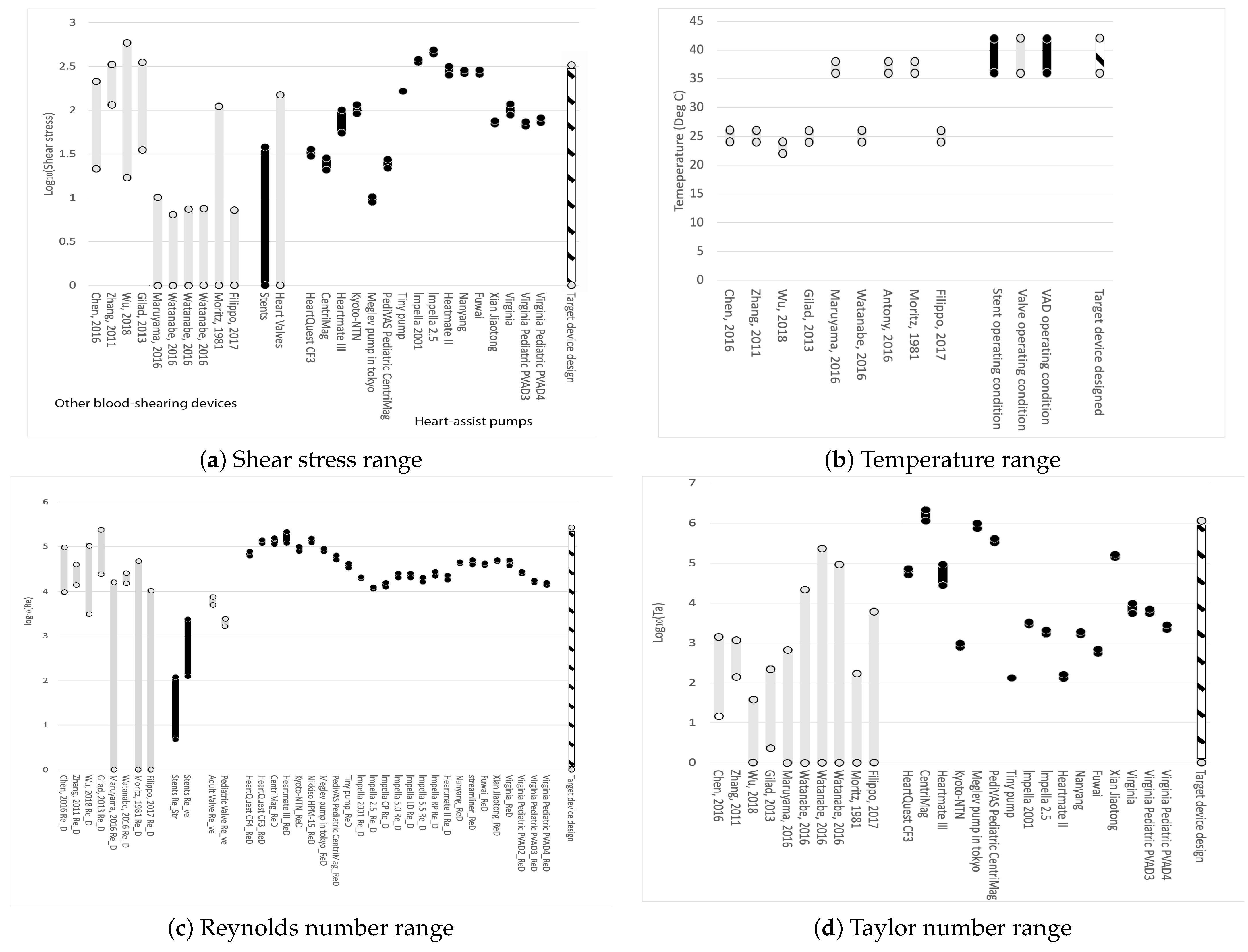
Figure 1a displays the range of shear stresses for the devices of interest. From left to right, grey represents other blood-shearing devices, black represents stents, grey indicates prosthetic heart valves, black shows heart-assist pumps, and the cross-hatched black-white bar on the far right represents the conditions of the blood-shearing device examined in this paper. It is evident that most blood-shearing devices are not designed to cover the shear stress range applicable to blood pumps. The blood-shearing device in this paper covers the entire range of commercially available stents, valves, and heart-assist pumps, excluding the highest values for Impella variants, which have the highest shear among heart-assist pumps. The exclusion of Impella’s maximum shear stress range is reasonable given that this device is known to induce very high shear stress levels and high hemolysis. Other micro-pumps are designed at lower shear stress values with the explicit purpose of generating less hemolysis than Impella.
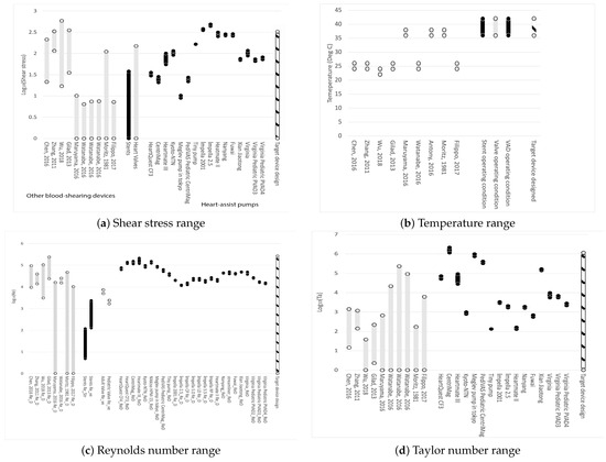
Figure 1.
Operating range of parameters of devices. From left to right: black represents other blood-shearing devices, grey represents stents; black shows prosthetic heart valves; grey shows heart-assist pumps; and the cross-hatched black-white bar on the far right represents the conditions of the blood-shearing device examined in this paper. Data from: Moritz, 1981 [111]; Zhang, 2011 [112]; Gilad, 2013 [113]; Chen, 2016 [114]; Maruyama, 2016 [115]; Watanabe, 2016 [116]; Antony, 2016 [117]; Filippo, 2017 [118]; Dimasi, 2017 [119]; Wu, 2018 [120]. References listed alphabetically in this Figure can be fund in the list of references by first author.
4.2. Temperature Considerations
Figure 1b shows that some existing blood-shearing test devices are designed for blood tests at 37 °C, which is the operational temperature for implanted medical devices in the human body. The blood temperature during testing is crucial from the perspective of shear flow. A 10 °C change can result in a viscosity change in the range of 10% to 20%, around 37 °C [113,121]. This implies that if experiments are conducted at room temperature (25 °C), even if the shear stress calculated using the room temperature viscosity is designed to cover the range of medical device operational conditions, the shear rate will deviate from the operational conditions. The shear rate is also proposed to be an important factor for flow-induced blood trauma [122]. The blood temperature during shearing experiments must be controlled at 37 °C in order to eliminate uncertainties.
4.3. Reynolds Number Considerations
Figure 1c demonstrates that the Reynolds number of the proposed device can encompass all commercial medical devices and shearing devices.
4.4. Taylor Number Considerations
Figure 1d illustrates the Taylor number range for existing devices and the device in this paper. It is evident that the proposed design could cover the entire range of Taylor numbers. Shearing devices constructed in the past have primarily focused on laminar and uniform shear flows, resulting in very small Taylor numbers that cannot accurately represent realistic blood flow conditions.
The Taylor numbers are generally larger for centrifugal pumps compared to axial pumps. This difference can be attributed in part to the fact that the gap clearance for axial pumps is often much smaller than that for centrifugal pumps. The critical Taylor number for flow transition from circular Couette flow to the vortex state is 1708 [123]. The pumps operate in a broad flow regime.
4.5. Basic Geometry
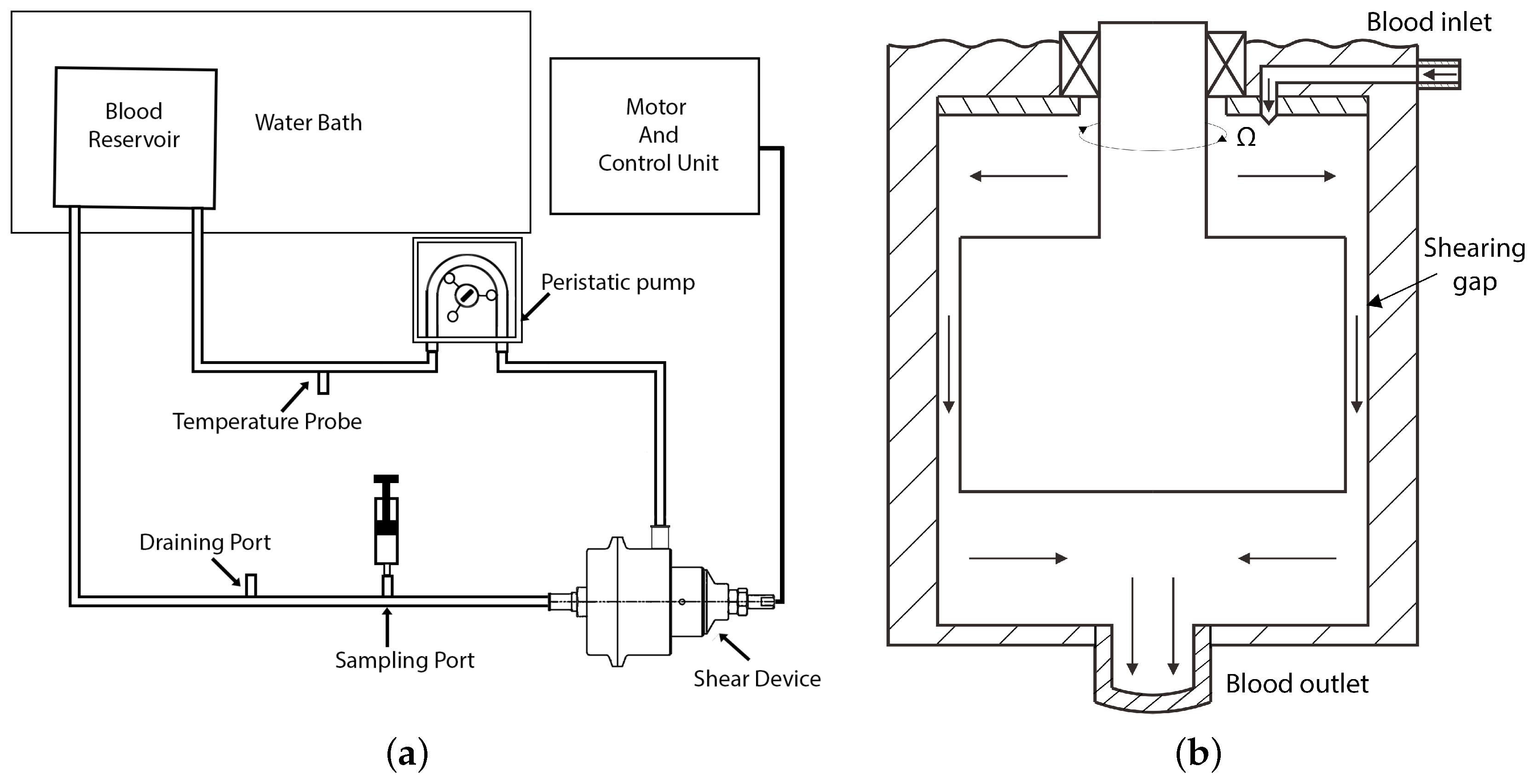
The geometric and physical parameters of the double-cylinder Couette-type blood-sharing device were selected to result in Reynolds numbers, Taylor numbers, and shear stress ranges representing all cardiovascular prosthetic devices. The maximum rotational speed of the inner rotor was set at 7000 rpm, with the outer rotor stationary. The other dimensions and parameters are summarized in Table 5. Blood residence time in the radial gap can be adjusted by changing the flow rate in the experimental loop from 5 L per minute to near 0 L per minute, varying from 4 ms to near infinity. In the simulation setup, a typical flow rate of 1 L per minute was used and the average residence time between the 0.2 mm and 1 mm gaps was varied from 19 milliseconds to about 90 milliseconds. The device was integrated into a proof-of-concept practical blood-shearing flow loop, as shown in Figure 2a. The schematic of the shear device is shown in Figure 2b. In this paper, we focus on the fundamentals of fluid flow in a simplified model of the radial gap, as illustrated in Figure 3. Blood trauma measurements in the practical device are presented in a separate publication [124].

Table 5.
Parameters for Couette device.
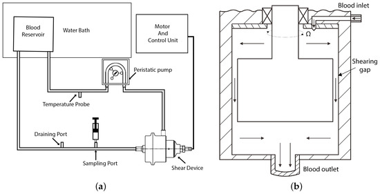
Figure 2.
Schematic of the experimental loop and shear device: (a) schematic of experimental loop and (b) schematic of the shear device showing the flow path (graph not to scale).
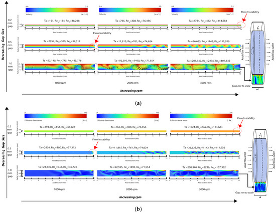
Figure 3.
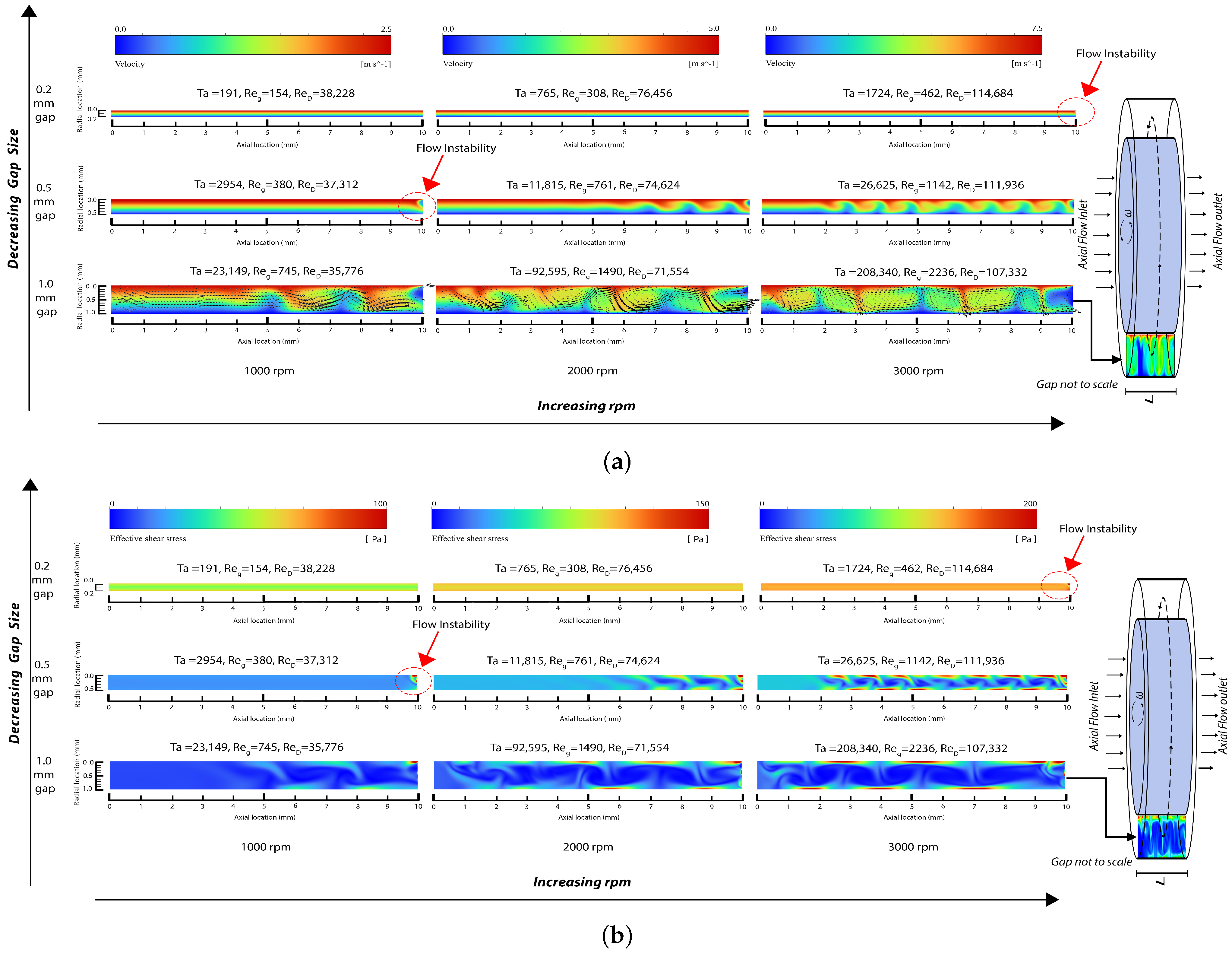
Snapshot of field output from numerical simulation: (a) velocity magnitude contour in the gap region with velocity vectors included for the largest gap rotor (note that the maximum velocity magnitude/color is different for each rpm) and (b) effective shear stress contour in the gap region (note that the maximum shear stress magnitude/color is different for each rpm).
5. Numerical Simulation of Representative Flow Fields
Blood is modeled as an incompressible Newtonian fluid with a density of = 1040 kg/m3 and dynamic viscosity of = 0.0035 Pa·s. The system comprises a 3D model consisting of two concentric cylinders with a height L of 10 mm. The inner cylinders have radii of R = 24.8 mm, R = 24.5 mm and R = 24.0 mm, while the outer cylinder has a radius of 25 mm, resulting in gap sizes d of 0.2 mm, 0.5 mm, and 1.0 mm. These configurations yield radius ratios , defined as
of 0.992, 0.980, and 0.960 along with aspect ratios (cylinder height to gap ratio) of 50, 20, and 10, respectively. Correspondingly, the entrance effects in the gap region are expected to be of relatively short length. This is corroborated by the similar results when using different inlet models, as discussed near the end of this section. The critical axial wavelength , which is indicative of flow disturbance transition based on linear stability analysis, is approximately [125]. This parameter suggests the presence of 5 to 25 axial wavelengths within the gap of our simplified geometry, supporting the application of the Taylor number in our analysis of the results in Section 6.
By examining three rotational speeds for the inner rotor rotating at 1000 rpm, 2000 rpm, and 3000 rpm, the simulations resulted in Taylor numbers in the range of 191 to 208,340, Reynolds numbers based on the inner rotor diameter ranging from 35,776 to 114,684, and Reynolds numbers based on the gap size ranging from 154 to 2236. As explained below, these results cover the range of laminar Couette flow, the beginning of flow disturbances, the generation of laminar Taylor vortices, and the generation of turbulent Taylor vortices.
Fluent’s ANSYS flow solver was used for a numerical simulation on a structured hexagonal mesh in the radial, azimuthal, and axial directions. The grid was gradually refined until further refinement did not significantly alter the computed results, indicating that the grid was sufficiently resolved. After mesh size optimization, the mesh between the two rotors comprised 50 cells in the radial direction, 400 cells in the azimuthal direction, and 500 cells in the axial direction, resulting in a total of 10 million hexahedral cells and about 10.3 million nodes (grid points). Pressure discretization was performed using a second-order scheme, while momentum discretization utilized a second-order upwind scheme. The simulation employed a viscous laminar model in the laminar region and an SST k- turbulent model in the turbulent region; the distinction between the two regions is further explained in the next section.
To verify the Newtonian assumption, we conducted additional simulations incorporating shear-thinning viscosity models such as the Casson model [126], Cross model, and Carreau–Yasuda model [127]. The results with these shear-thinning models are similar to Newtonian results, and both are similar to the results for a homogeneous “top hat” plug–flow inlet and a laminar parabolic axial flow inlet coupled with a Couette azimuthal flow inlet. Further, at these axial flow velocities and axial flow Reynolds numbers (about 31), a turbulent inflow model would re-laminarize very fast. However, the turbulent model and top-hat inflow model (which is an approximation for turbulent flow) both have slightly higher shear stress than laminar flow. All of the above cases lead to very similar results. The Newtonian results with laminar parabolic flow and Couette azimuthal inlet flow are presented below.
Shear thinning model simulations were performed for gap sizes corresponding to our experimental conditions (200 to 1000 m). The results indicate minimal differences in flow characteristics between these models, reaffirming the appropriateness of the Newtonian assumption in our research. This conclusion is further supported by the fact that human red blood cells, with a diameter of less than 10 m and a thickness of less than 3 m, are substantially smaller than the gaps considered in the other studies in the next sentence as well as in our study. Additionally, previous numerical studies such as Zhang et al. [112] (gap size 100 m), Fraser et al. [128] (gap size 100 m), and Wu et al. [120] (gap size 50 m) have successfully employed the Newtonian fluid assumption in comparable contexts, reinforcing its suitability for our study.
6. Results and Discussion
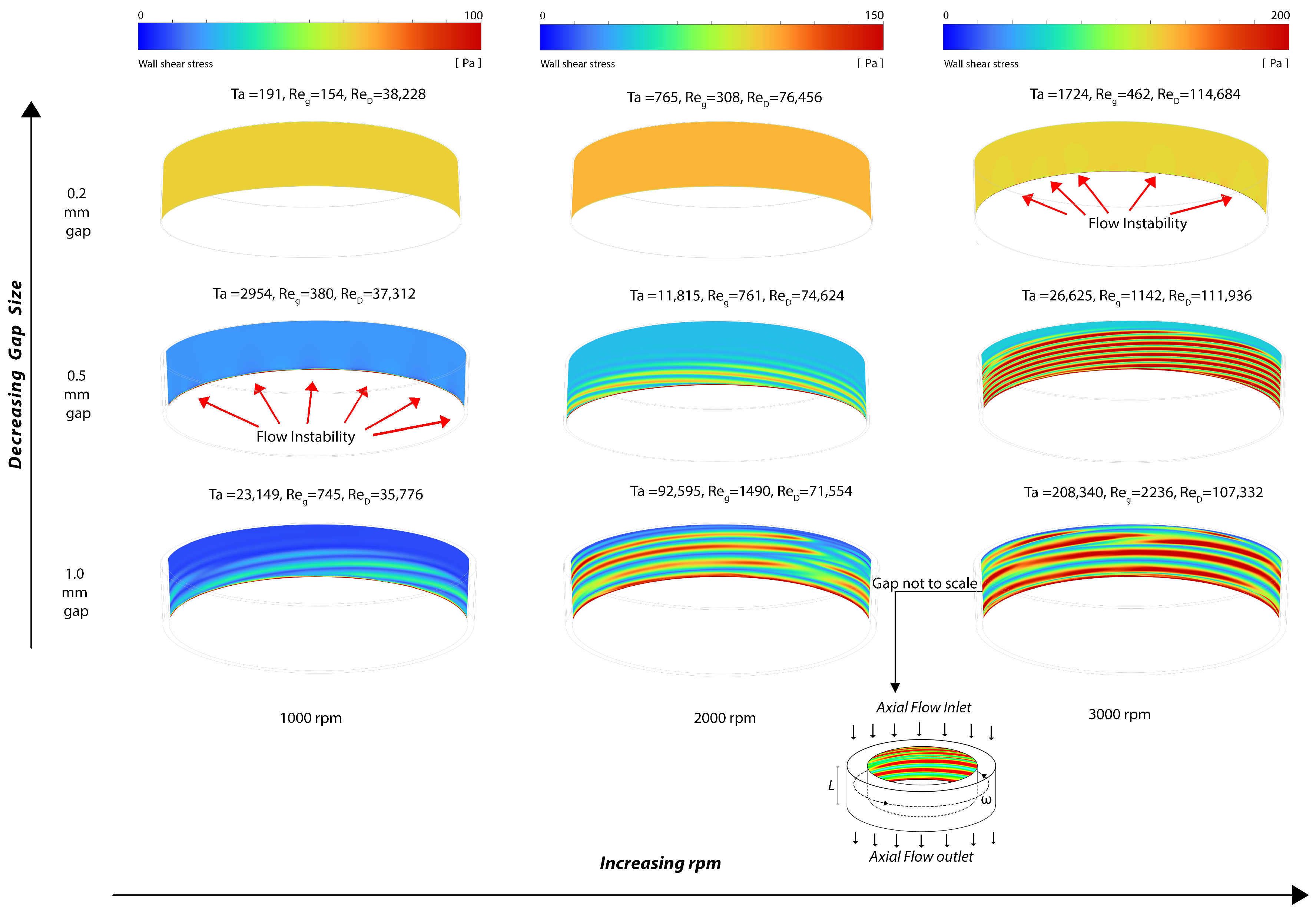
The distribution of velocity magnitudes within the gap region is depicted in Figure 3a, along with in-plane velocity vector plots for the 1.0 mm gap rotor indicating the flow direction. The field solution of the effective shear stress, defined as (where represents the deviatory stress), is illustrated in Figure 3b. Additionally, the wall shear stress at the rotating cylinder is visualized in Figure 4.
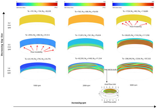
Figure 4.
Snapshot of the wall shear stress distribution at the rotating cylinder wall (note that the maximum wall shear stress magnitude/color is different for each rpm).
The laminar flow solver was used for the 0.2 mm gap for 1000 and 2000 rpm, where the Reynolds numbers and resultant flow fields indicate that the flow is laminar. As the Reynolds numbers increase, small velocity disturbances begin to appear near the outlet at Ta = 1724. These flow disturbances are more pronounced with the 0.5 mm gap and at 1000 rpm as Ta increases, and are fully formed into laminar vortices near the outlet region at 0.5 mm gap and 2000 rpm, where Ta = 11,815. Both laminar and SST turbulent solvers were used in the 1 mm gap at 1000 rpm, 2000 rpm, and 3000 rpm, where they provided substantially the same results in terms of vortices while the boundary layers were thinner for the SST turbulent models. Furthermore, Figure 3 shows an increase in the wavelength of the vortices when the gap increases from 0.5 mm to 1 mm at 3000 rpm. This observation qualitatively aligns with linear theory, which indicates that the instability axial wavelength is proportional to the gap width (refer to Section 5).
The simulation outcomes affirm the ability of the Couette-type blood-shearing device presented in this paper to examine blood flows with laminar and turbulent flow patterns and with Taylor vortex structures representative of those found across the range of cardiovascular prosthetic devices, stents, valves, and heart-assist pumps. Before reaching a Taylor number of 1724, any instabilities in the flow are suppressed and the predominant flow fields exhibit a uniform distribution of shear. However, upon surpassing the Taylor number threshold of 1724, disturbances in the flow begin to arise at the solid fluid boundary and continue to increase with increasing Taylor numbers, leading to local velocity disturbances beyond those of pure Couette flow. As the Taylor number continues to rise, the formation of vortices becomes evident, further augmenting the shear state. Additional increases in the Reynolds and Taylor numbers result in turbulent flows. These disturbances result in increases in the flow shear of blood in contact with the solid boundary, consequently elevating the shear stress and increasing blood trauma. Bovine blood trauma measurements caused by the device described in this paper confirmed that increasing the Reynolds and Taylor numbers increases blood trauma, as reported in a separate paper [124]; however, this clinical measurement aspect is beyond the scope of the present paper.
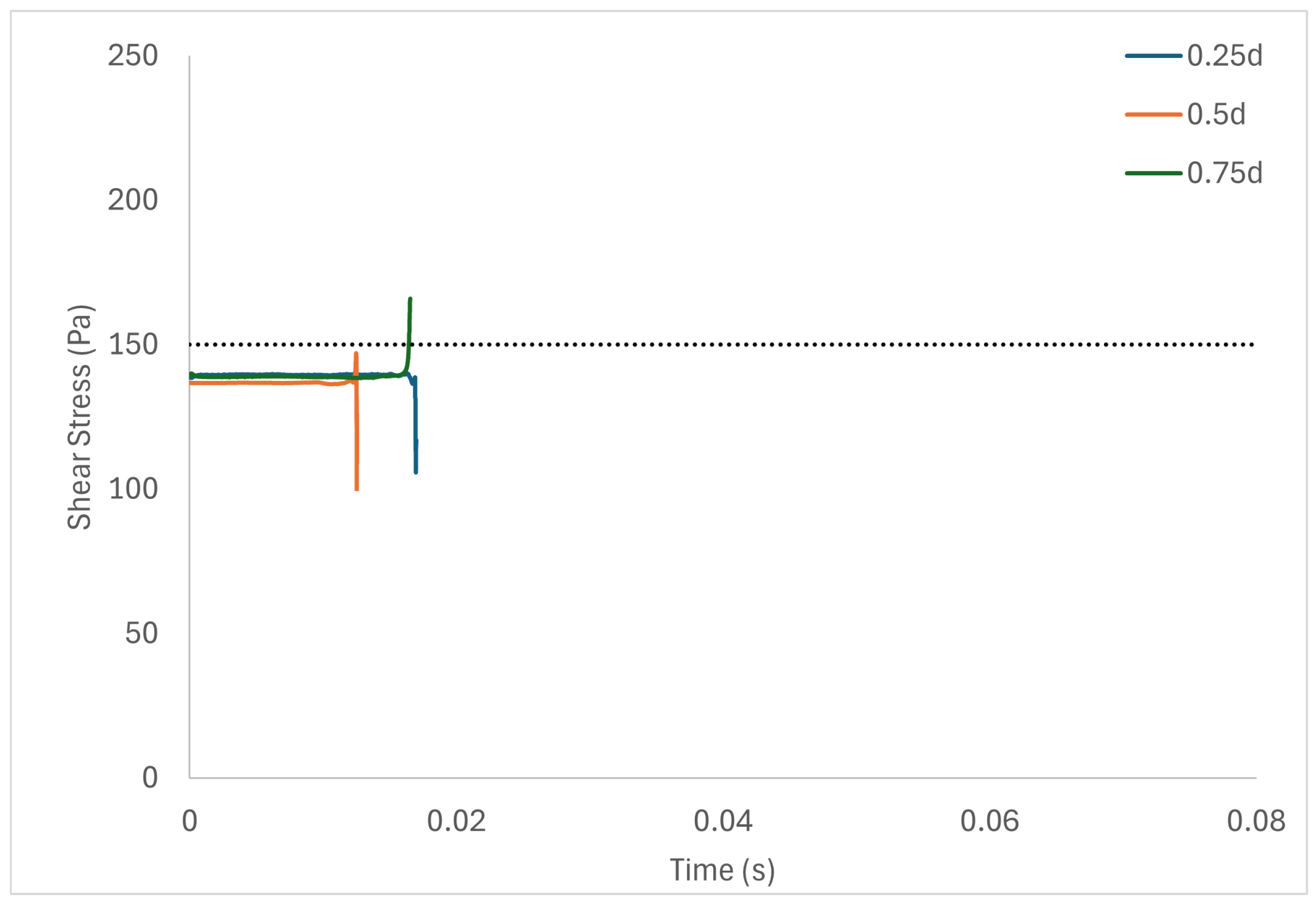
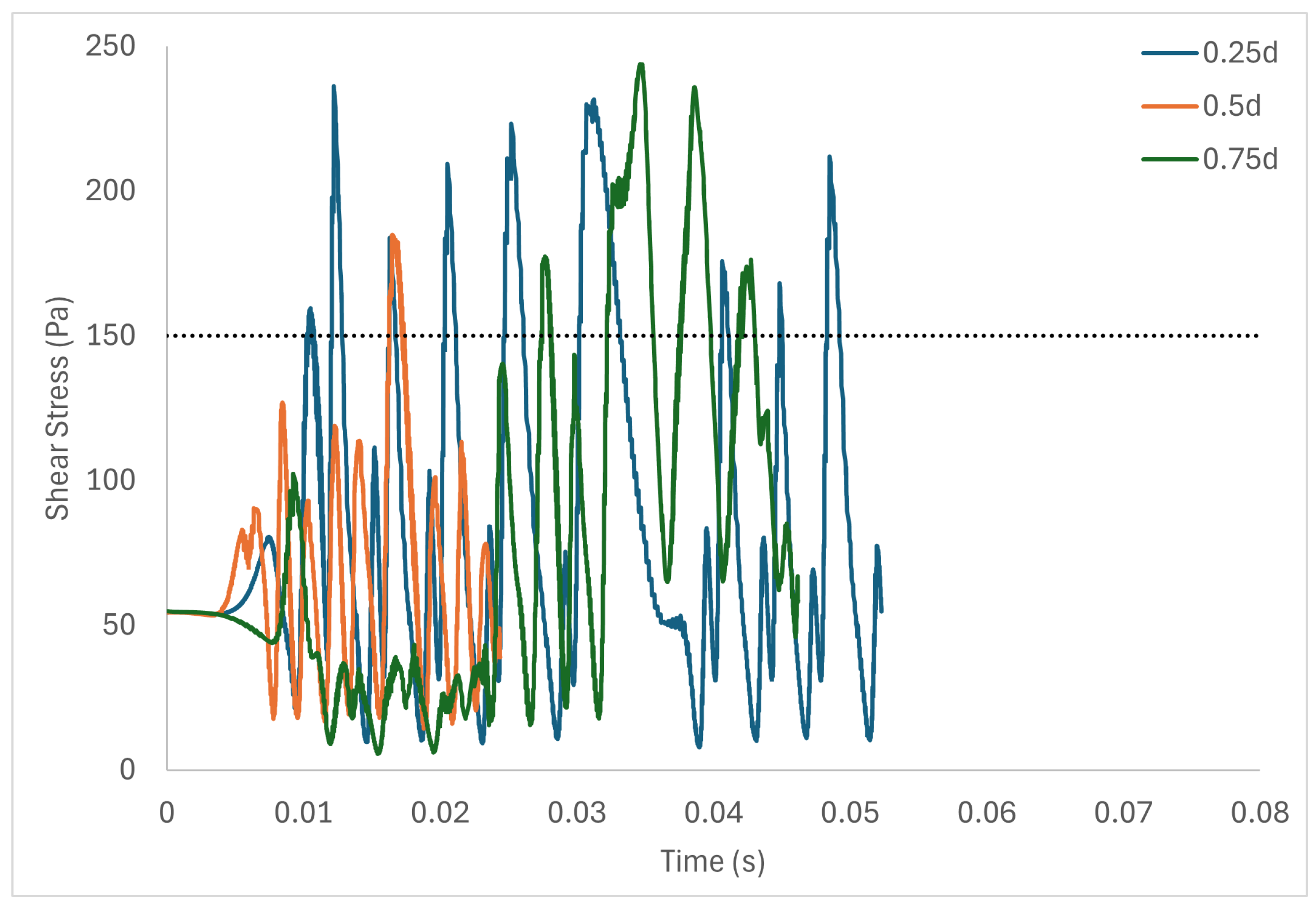
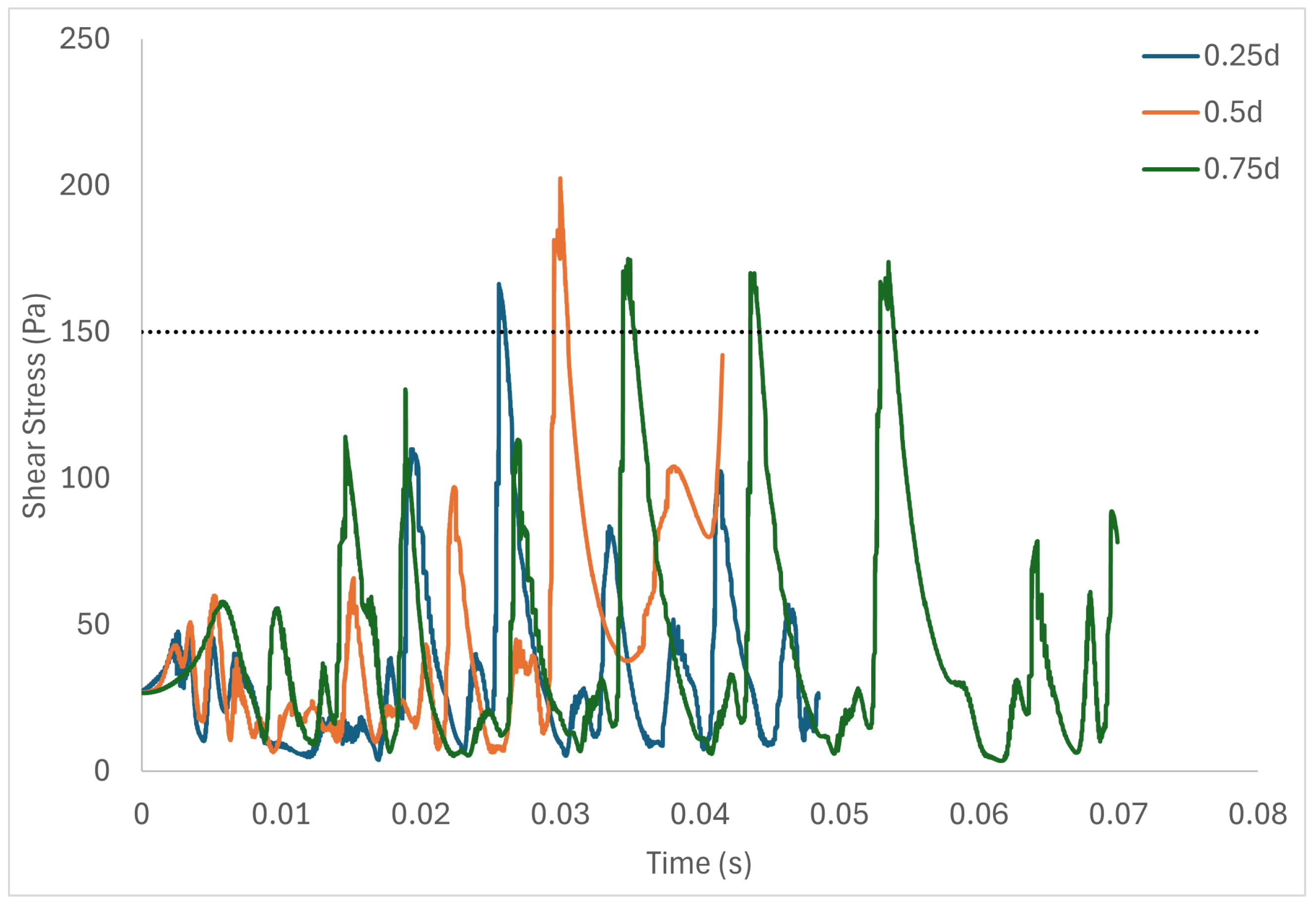
Table 6 shows the volume of fluid elements experiencing stress levels surpassing the hemolysis threshold of 150 Pa [129]. Additionally, particle pathline analyses were conducted for rotors operating at 3000 rpm, initiating trajectories from three inlet points of the radial gap positioned at d, d, and d. These pathline results are depicted in Figure 5, Figure 6 and Figure 7 for rotor gaps of 0.2 mm, 0.5 mm, and 1.0 mm, respectively. The 0.5 mm rotor at 3000 rpm exhibited the highest volume of fluid exposed to super-hemolytic shear stresses compared to the 1.0 mm and 0.2 mm gap rotors. This rotor also generated more vortices. Notably, the 0.5 mm rotor showed an intermediate average exposure time, whereas the 1.0 mm gap rotor exhibited the longest exposure times and the 0.2 mm gap rotor the shortest. The reduced exposure duration and increased vortex formation in the 0.5 mm gap resulted in higher fluctuations in shear stress. As depicted in the pathline figures, particles within the 0.5 mm gap experienced the highest frequency of stress fluctuations and were more likely to encounter shear stress levels exceeding 150 Pa. These results suggest that at 3000 rpm the 0.5 mm gap rotor poses the highest risk for inducing hemolysis. This agrees with the blood trauma measurement results in [124].

Table 6.
Volume of fluid experiencing stress levels above the hemolysis threshold.
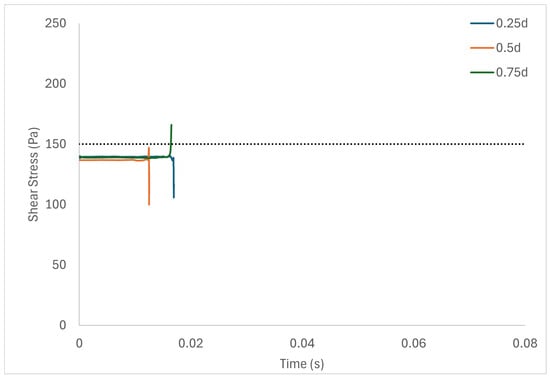
Figure 5.
Stress fluctuation along three pathlines for the 0.2 mm gap rotor.
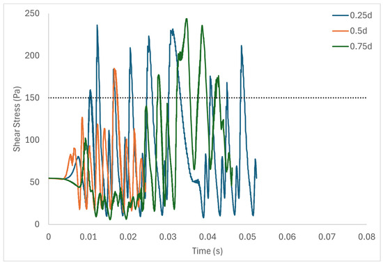
Figure 6.
Stress fluctuation along three pathlines for the 0.5 mm gap rotor.
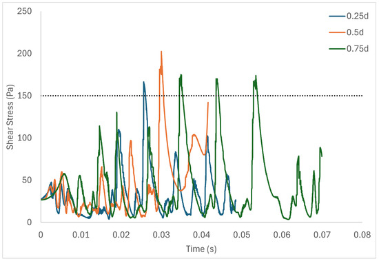
Figure 7.
Stress fluctuation along three pathlines for the 1.0 mm gap rotor.
Figure 5 shows a short adjustment region near the inlet due to the inflow conditions, with the flow settling to a steady state soon afterwards. On the other hand, in higher Taylor numbers, where there is high flow unsteadiness, the adjustment region is not evident. Figure 3a,b and Figure 4 show the simulation results obtained with the parabolic axial velocity with a Couette azimuthal velocity distribution and Newtonian fluid. Simulations with the plug-flow “top hat” inlet velocity profile indicate a marginally longer inlet adjustment length and marginally larger stress levels, but do not substantially change the results.
In this paper, we have assumed that the flow patterns and characteristics generated by the double-cylinder Couette-type blood-shearing device, including laminar, vortex, and turbulent flows, sufficiently represent the flow conditions found in high shear flow regions of various cardiovascular prosthetic devices. While this model provides valuable insights, we acknowledge that complete similarity with all types of cardiovascular prosthetic devices may not be achievable due to differences in device geometries.
Our numerical study relies on the assumption that blood can be approximated as a Newtonian fluid. While this simplification is justified by previous studies in comparable contexts and our additional simulations using shear-thinning viscosity models, it is important to acknowledge that blood exhibits other complex non-Newtonian behaviors [130,131]. Incorporating additional non-Newtonian characteristics into our simulations and the full geometry of the device in a future study would provide a more accurate representation of blood rheology and improve the relevance of the study to real-world applications.
7. Conclusions
Previous blood-shearing devices do not cover the full regime of key flow parameters such as Reynolds numbers, Taylor numbers, and shear stress levels experienced by blood across the full range of operating conditions of cardiovascular prosthetic devices such as stents, valves, and heart-assist pumps. Thus, clinical measurements of blood trauma from these different blood-shearing devices have a limited range of applicability. This paper outlines geometric and flow parameter selection for the design of a Couette-type blood-shearing device in a manner that ensures that such devices cover the full range of the above key parameters of interest for all three types of cardiovascular prosthetic devices. Therefore, the flow patterns in the device in this paper are representative of those found in the full range of operation of all three types of cardiovascular prosthetic devices. The outcome is that the numerical data obtained from this device can be related to all such prosthetic devices and all flow conditions, making the shearing-device results widely applicable across the field. Numerical simulations have verified the device’s capacity to generate both homogeneous and inhomogeneous flow fields as well as laminar and turbulent flow fields characterized by instabilities and vortices that can cause subsequent blood trauma. Future investigations will utilize our internally developed high-fidelity red blood cell computational model to further explore non-Newtonian behaviors in blood flows under highly constrained gaps [131].
Author Contributions
Conceptualization, T.A. and X.C.; methodology, T.A., X.C. and E.J.A.; validation, X.C., T.A. and E.J.A.; formal analysis, T.A., X.C., E.J.A., S.I. and M.M.A.; investigation, T.A., X.C., E.J.A., S.I. and M.M.A.; data curation, X.C. and P.H.; writing—original draft preparation, X.C. and T.A.; writing—review and editing, X.C., T.A. and E.J.A.; supervision, T.A.; project administration, T.A. and X.C. All authors have read and agreed to the published version of the manuscript.
Funding
This research received no external funding.
Data Availability Statement
This is a numerical simulations paper. Data sharing is not applicable to this article.
Acknowledgments
The authors are grateful for the contributions of Ed Ising, Exospace LLC, to the manufacture of the blood-shearing device described in the paper.
Conflicts of Interest
The authors declare no conflicts of interest.
Nomenclature
The following abbreviations are used in this manuscript:
| Latin | |
| D | Diameter [m] |
| d | Radial gap size [m] |
| L | Height [m] |
| R | Radius [m] |
| Reynolds number | |
| Taylor number | |
| u | Velocity [m s−1] |
| Greek | |
| Dynamic viscosity [kg m−1 s−1 or Pa·s] | |
| Rotation speed [s−1] | |
| Density [kg m−3] | |
| Deviatoric stress [kg m−1 s−2] |
| Superscripts and subscripts | |
| D | Diameter |
| g | Radial gap |
| in | Inner rotor |
| R | Radius |
| str | Strut |
| ve | Vessel |
References
- Girdhar, G.; Bluestein, D. Biological effects of dynamic shear stress in cardiovascular pathologies and devices. Expert Rev. Med. Devices 2008, 5, 167–181. [Google Scholar] [CrossRef] [PubMed]
- LaDisa, J.; Guler, I.; Olson, L.; Hettrick, D.; Kersten, J.; Warltier, D.; Pagel, P. Three-Dimensional Computational Fluid Dynamics Modeling of Alterations in Coronary Wall Shear Stress Produced by Stent Implantation. Ann. Biomed. Eng. 2003, 31, 972–980. [Google Scholar] [CrossRef] [PubMed]
- LaDisa, J.; Olson, L.; Douglas, H.A.; Warltier, D.; Kersten, J.; Pagel, P. Alterations in regional vascular geometry produced by theoretical stent implantation influence distributions of wall shear stress: Analysis of a curved coronary artery using 3D computational fluid dynamics modeling. Biomed. Eng. Online 2006, 5, 40. [Google Scholar] [CrossRef]
- LaDisa, J.; Olson, L.; Hettrick, D.; Warltier, D.; Kersten, J.; Pagel, P. Axial stent strut angle influences wall shear stress after stent implantation: Analysis using 3D computational fluid dynamics models of stent foreshortening. Biomed. Eng. Online 2005, 4, 59. [Google Scholar] [CrossRef] [PubMed]
- Charonko, J.; Karri, S.; Schmieg, J.; Prabhu, S.; Vlachos, P. In Vitro, Time-Resolved PIV Comparison of the Effect of Stent Design on Wall Shear Stress. Ann. Biomed. Eng. 2009, 37, 1310–1321. [Google Scholar] [CrossRef]
- Stone, P.; Coskun, A.; Croce, K. Evolving insights into the role of local shear stress in late stent failure from neoatherosclerosis formation and plaque destabilization. Int. J. Cardiol. 2018, 272, 45–46. [Google Scholar] [CrossRef] [PubMed]
- Cutlip, D.E.; Nakazawa, G.; Krucoff, M.W.; Vorpahl, M.; Mehran, R.; Finn, A.V.; Vranckx, P.; Kimmelstiel, C.; Berger, C.; Petersen, J.L.; et al. Autopsy Validation Study of the Academic Research Consortium Stent Thrombosis Definition. JACC Cardiovasc. Interv. 2011, 4, 554–559. [Google Scholar] [CrossRef]
- Papafaklis, M.; Bourantas, C.; Theodorakis, P.; Katsouras, C.; Fotiadis, D.; Michalis, L. Relationship of shear stress with in-stent restenosis: Bare metal stenting and the effect of brachytherapy. Int. J. Cardiol. 2008, 134, 25–32. [Google Scholar] [CrossRef]
- Wentzel, J.J.; Krams, R.; Schuurbiers, J.C.H.; Oomen, J.A.; Kloet, J.; van der Giessen, W.J.; Serruys, P.W.; Slager, C.J. Relationship between Neointimal Thickness and Shear Stress after Wallstent Implantation in Human Coronary Arteries. Circulation 2001, 103, 1740–1745. [Google Scholar] [CrossRef]
- Stone, P.H.; Coskun, A.U.; Kinlay, S.; Clark, M.E.; Sonka, M.; Wahle, A.; Ilegbusi, O.J.; Yeghiazarians, Y.; Popma, J.J.; Orav, J.; et al. Effect of Endothelial Shear Stress on the Progression of Coronary Artery Disease, Vascular Remodeling, and In-Stent Restenosis in Humans. Circulation 2003, 108, 438–444. [Google Scholar] [CrossRef]
- Papafaklis, M.I.; Bourantas, C.V.; Theodorakis, P.E.; Katsouras, C.S.; Naka, K.K.; Fotiadis, D.I.; Michalis, L.K. The Effect of Shear Stress on Neointimal Response Following Sirolimus- and Paclitaxel-Eluting Stent Implantation Compared with Bare-Metal Stents in Humans. JACC Cardiovasc. Interv. 2010, 3, 1181–1189. [Google Scholar] [CrossRef] [PubMed]
- Economou, F.; Katranas, S.; Giannoglou, G.; Gemitzis, K.; Styliadis, I.; Efthimiadis, G.; Karvounis, H.; Ziakas, A. Impact of stent implantation on endothelial shear stress. Herz 2016, 42, 505–508. [Google Scholar] [CrossRef]
- Carlier, S.; van Damme, L.V.; Blommerde, C.P.; Wentzel, J.; van Langehove, G.; Verheye, S.; Kockx, M.; Knaapen, M.; Cheng, C.; Gijsen, F.; et al. Augmentation of Wall Shear Stress Inhibits Neointimal Hyperplasia After Stent Implantation: Inhibition Through Reduction of Inflammation? Circ. J. Am. Heart Assoc. 2003, 107, 2741–2746. [Google Scholar] [CrossRef] [PubMed]
- Wentzel, J.J.; Whelan, D.M.; van der Giessen, W.J.; van Beusekom, H.M.; Andhyiswara, I.; Serruys, P.W.; Slager, C.J.; Krams, R. Coronary stent implantation changes 3-D vessel geometry and 3-D shear stress distribution. J. Biomech. 2000, 33, 1287–1295. [Google Scholar] [CrossRef] [PubMed]
- Shishido, K.; Antoniadis, A.P.; Takahashi, S.; Tsuda, M.; Mizuno, S.; Andreou, I.; Papafaklis, M.I.; Coskun, A.U.; O’Brien, C.; Feldman, C.L.; et al. Effects of Low Endothelial Shear Stress after Stent Implantation on Subsequent Neointimal Hyperplasia and Clinical Outcomes in Humans. J. Am. Heart Assoc. 2016, 5, e002949. [Google Scholar] [CrossRef] [PubMed]
- Jiménez, J.M.; Davies, P.F. Hemodynamically Driven Stent Strut Design. Ann. Biomed. Eng. 2009, 37, 1483–1494. [Google Scholar] [CrossRef] [PubMed]
- Mejìa, J.; Ruzzeh, B.; Mongrain, R.; Leask, R.; Bertrand, O. Evaluation of the effect of stent strut profile on shear stress distribution using statistical moments. Biomed. Eng. Online 2009, 8, 8. [Google Scholar] [CrossRef] [PubMed]
- Kokkalis, E.; Aristokleous, N.; Houston, J. Haemodynamics and Flow Modification Stents for Peripheral Arterial Disease: A Review. Ann. Biomed. Eng. 2015, 44, 466–476. [Google Scholar] [CrossRef]
- Peacock, J.; Hankins, S.; Jones, T.; Lutz, R. Flow instabilities induced by coronary artery stents: Assessment with an in vitro pulse duplicator. J. Biomech. 1995, 28, 17–26. [Google Scholar] [CrossRef]
- Hofma, S.; Whelan, D.; van Beusekom, H.; Verdouw, P.; van der Giessen, W. Increasing arterial wall injury after long-term implantation of two types of stent in a porcine coronary model. Eur. Heart J. 1998, 19, 601–609. [Google Scholar] [CrossRef]
- Hu, Z.Y.; Chen, S.L.; Zhang, J.J.; Shan, S.J.; Liu, Z.Z.; Ye, F.; Kan, J.; Xu, H.M.; Nguyen, K.; Kwan, T.; et al. Distribution and Magnitude of Shear Stress after Coronary Bifurcation Lesions Stenting with the Classical Crush Technique: A New Predictor for In-Stent Restenosis. J. Interv. Cardiol. 2010, 23, 330–340. [Google Scholar] [CrossRef] [PubMed]
- Ng, J.; Bourantas, C.V.; Torii, R.; Ang, H.Y.; Tenekecioglu, E.; Serruys, P.W.; Foin, N. Local Hemodynamic Forces After Stenting. Arterioscler. Thromb. Vasc. Biol. 2017, 37, 2231–2242. [Google Scholar] [CrossRef] [PubMed]
- Jenei, C.; Balogh, E.; Szabó, G.; Dézsi, C.; Koszegi, Z. Wall shear stress in the development of in-stent restenosis revisited. A critical review of clinical data on shear stress after intracoronary stent implantation. Cardiol. J. 2016, 23, 365–373. [Google Scholar] [CrossRef] [PubMed]
- Koskinas, K.C.; Chatzizisis, Y.S.; Antoniadis, A.P.; Giannoglou, G.D. Role of Endothelial Shear Stress in Stent Restenosis and Thrombosis: Pathophysiologic Mechanisms and Implications for Clinical Translation. J. Am. Coll. Cardiol. 2012, 59, 1337–1349. [Google Scholar] [CrossRef]
- Azari, S.; Rezapour, A.; Omidi, N.; Alipour, V.; Tajdini, M.; Sadeghian, S.; Bragazzi, N.L. A systematic review of the cost-effectiveness of heart valve replacement with a mechanical versus biological prosthesis in patients with heart valvular disease. Heart Fail. Rev. 2020, 25, 495–503. [Google Scholar] [CrossRef]
- Li, R.L.; Russ, J.; Paschalides, C.; Ferrari, G.; Waisman, H.; Kysar, J.W.; Kalfa, D. Mechanical considerations for polymeric heart valve development: Biomechanics, materials, design and manufacturing. Biomaterials 2019, 225, 119493. [Google Scholar] [CrossRef]
- Baldwin, A.C.W.; Tolis, G. Tissue Valve Degeneration and Mechanical Valve Failure. Curr. Treat. Options Cardiovasc. Med. 2019, 21, 33. [Google Scholar] [CrossRef]
- David, T. How to Decide Between a Bioprosthetic and Mechanical Valve. Can. J. Cardiol. 2020, 37, 1121–1123. [Google Scholar] [CrossRef]
- Dasi, L.P.; Simon, H.A.; Sucosky, P.; Yoganathan, A.P. Fluid mechanics of artificial heart valves. Clin. Exp. Pharmacol. Physiol. 2009, 36, 225–237. [Google Scholar] [CrossRef]
- Barakat, M.; Dvir, D.; Azadani, A.N. Fluid Dynamic Characterization of Transcatheter Aortic Valves Using Particle Image Velocimetry. Artif. Organs 2018, 42, E357–E368. [Google Scholar] [CrossRef]
- Gürsoy, M.O.; Kalçık, M.; Yesin, M.; Karakoyun, S.; Bayam, E.; Gündüz, S.; Özkan, M. A global perspective on mechanical prosthetic heart valve thrombosis: Diagnostic and therapeutic challenges. Anatol. J. Cardiol. 2016, 16, 980–989. [Google Scholar] [PubMed]
- Boloori_Zadeh, P.; Corbett, S.C.; Nayeb-Hashemi, H. Effects of fluid flow shear rate and surface roughness on the calcification of polymeric heart valve leaflet. Mater. Sci. Eng. C 2013, 33, 2770–2775. [Google Scholar] [CrossRef] [PubMed]
- Lim, W.Y.; Lloyd, G.; Bhattacharyya, S. Mechanical and surgical bioprosthetic valve thrombosis. Heart 2017, 103, 1934–1941. [Google Scholar] [CrossRef]
- Mirsadraee, S.; Sellers, S.; Duncan, A.; Hamadanchi, A.; Gorog, D. Bioprosthetic valve thrombosis and degeneration following transcatheter aortic valve implantation (TAVI). Clin. Radiol. 2021, 76, 73.e39–73.e47. [Google Scholar] [CrossRef]
- Hatoum, H.; Gooden, S.; Heitkemper, M.; Blum, K.M.; Zakko, J.; Bocks, M.; Yi, T.; Wu, Y.L.; Wang, Y.; Breuer, C.K.; et al. Fetal Transcatheter Trileaflet Heart Valve Hemodynamics: Implications of Scaling on Valve Mechanics and Turbulence. Ann. Biomed. Eng. 2020, 48, 1683–1693. [Google Scholar] [CrossRef]
- Laflamme, J.; Puri, R.; Urena, M.; Laflamme, L.; DeLarochellière, H.; Abdul-Jawad Altisent, O.; del Trigo, M.; Campelo-Parada, F.; DeLarochellière, R.; Paradis, J.M.; et al. Incidence and Risk Factors of Hemolysis after Transcatheter Aortic Valve Implantation With a Balloon-Expandable Valve. Am. J. Cardiol. 2015, 115, 1574–1579. [Google Scholar] [CrossRef]
- Hedayat, M.; Borazjani, I. Comparison of platelet activation through hinge vs bulk flow in bileaflet mechanical heart valves. J. Biomech. 2019, 83, 280–290. [Google Scholar] [CrossRef]
- Krafczyk, M.; Tölke, J.; Rank, E.; Schulz, M. Two-dimensional simulation of fluidñstructure interaction using lattice-Boltzmann methods. Comput. Struct. 2001, 79, 2031–2037. [Google Scholar] [CrossRef]
- Gilmanov, A.; Sotiropoulos, F. Comparative hemodynamics in an aorta with bicuspid and trileaflet valves. Theor. Comput. Fluid Dyn. 2016, 30, 67–85. [Google Scholar] [CrossRef]
- Kang, Y.; Hwang, H.Y.; Sohn, S.; Choi, J.W.; Kim, K.H.; Kim, K.B. Fifteen-Year Outcomes After Bioprosthetic and Mechanical Tricuspid Valve Replacement. Ann. Thorac. Surg. 2020, 110, 1564–1571. [Google Scholar] [CrossRef]
- IJsselhof, R.J.; Slieker, M.G.; Hazekamp, M.G.; Accord, R.; van Wetten, H.; Haas, F.; Schoof, P.H. Mitral Valve Replacement with the 15-mm Mechanical Valve: A 20-Year Multicenter Experience. Ann. Thorac. Surg. 2020, 110, 956–961. [Google Scholar] [CrossRef] [PubMed]
- Vu, V.; May-Newman, K. Bileaflet Prosthesis Design and Orientation Affect Fluid Shear, Residence Time, and Thrombus Formation. J. Cardiothorac. Vasc. Anesth. 2019, 33, 2870–2872. [Google Scholar] [CrossRef] [PubMed]
- Yoganathan, A.P.; Corcoran, W.H.; Harrison, E.C.; Carl, J.R. The Björk-Shiley aortic prosthesis: Flow characteristics, thrombus formation and tissue overgrowth. Circulation 1978, 58, 70–76. [Google Scholar] [CrossRef] [PubMed]
- Kim, W.; Choi, H.; Kweon, J.; Yang, D.H.; Kim, Y.H. Effects of pannus formation on the flow around a bileaflet mechanical heart valve. PLoS ONE 2020, 15, e0234341. [Google Scholar] [CrossRef] [PubMed]
- Darwazah, A.K. Recurrent pannus formation causing prosthetic aortic valve dysfunction: Is excision without valve re-replacement applicable? J. Cardiothorac. Surg. 2012, 7, 62. [Google Scholar] [CrossRef] [PubMed]
- Ha, H.; Koo, H.J.; Huh, H.K.; Kim, G.B.; Kweon, J.; Kim, N.; Kim, Y.H.; Kang, J.W.; Lim, T.H.; Song, J.K.; et al. Effect of pannus formation on the prosthetic heart valve: In vitro demonstration using particle image velocimetry. PLoS ONE 2018, 13, e0199792. [Google Scholar] [CrossRef]
- Karakoyun, S.; Ozan Gürsoy, M.; Yesin, M.; Kalçik, M.; Astarcioglu, M.A.; Gündüz, S.; Emrah Oguz, A.; Çoban Kökten, S.; Nimet Karadayi, A.; Tuncer, A.; et al. Histopathological and Immunohistochemical Evaluation of Pannus Tissue in Patients with Prosthetic Valve Dysfunction. J. Heart Valve Dis. 2016, 25, 104–111. [Google Scholar]
- Weidemann, H.; Müller, K.M.; Hennig, E.; Meissler, M.; Bücherl, E.S. Experience with Vascular Grafts in total Artificial Heart Replacement. Int. J. Artif. Organs 1990, 13, 288–292. [Google Scholar] [CrossRef]
- May-Newman, K.; Montes, R.; Campos, J.; Marquez-Maya, N.; Vu, V.; Zebrowski, E.; Motomura, T.; Benkowski, R. Reducing regional flow stasis and improving intraventricular hemodynamics with a tipless inflow cannula design: An in vitro flow visualization study using the EVAHEART LVAD. Artif. Organs 2019, 43, 834–848. [Google Scholar] [CrossRef]
- Hatoum, H.; Dollery, J.; Lilly, S.M.; Crestanello, J.A.; Dasi, L.P. Effect of severe bioprosthetic valve tissue ingrowth and inflow calcification on valve-in-valve performance. J. Biomech. 2018, 74, 171–179. [Google Scholar] [CrossRef]
- Misawa, Y. Valve-related complications after mechanical heart valve implantation. Surg. Today 2015, 45, 1205–1209. [Google Scholar] [CrossRef] [PubMed]
- Starling, R.C.; Moazami, N.; Silvestry, S.C.; Ewald, G.; Rogers, J.G.; Milano, C.A.; Rame, J.E.; Acker, M.A.; Blackstone, E.H.; Ehrlinger, J.; et al. Unexpected Abrupt Increase in Left Ventricular Assist Device Thrombosis. N. Engl. J. Med. 2014, 370, 33–40. [Google Scholar] [CrossRef] [PubMed]
- Davis, M.E.; Haglund, N.A.; Tricarico, N.M.; Matafonov, A.; Gailani, D.; Maltais, S. Immediate Recovery of Acquired von Willebrand Syndrome After Left Ventricular Assist Device Explantation: Implications for Heart Transplantation. ASAIO J. 2015, 61, e1–e4. [Google Scholar] [CrossRef] [PubMed]
- National Heart Lung and Blood Institute. The Diagnosis, Evaluation and Management of von Willebrand Disease. 2007. Available online: https://www.nhlbi.nih.gov/sites/default/files/media/docs/vwd.pdf (accessed on 22 June 2024).
- Meyer, A.L.; Malehsa, D.; Budde, U.; Bara, C.; Haverich, A.; Strueber, M. Acquired von Willebrand Syndrome in Patients With a Centrifugal or Axial Continuous Flow Left Ventricular Assist Device. JACC Heart Fail. 2014, 2, 141–145. [Google Scholar] [CrossRef] [PubMed]
- Uriel, N.; Pak, S.W.; Jorde, U.P.; Jude, B.; Susen, S.; Vincentelli, A.; Ennezat, P.V.; Cappleman, S.; Naka, Y.; Mancini, D. Acquired von Willebrand Syndrome After Continuous-Flow Mechanical Device Support Contributes to a High Prevalence of Bleeding During Long-Term Support and at the Time of Transplantation. J. Am. Coll. Cardiol. 2010, 56, 1207–1213. [Google Scholar] [CrossRef] [PubMed]
- Bartoli, C.R.; Zhang, D.; Kang, J.; Hennessy-Strahs, S.; Restle, D.; Howard, J.; Redline, G.; Bermudez, C.; Atluri, P.; Acker, M.A. Clinical and In Vitro Evidence That Subclinical Hemolysis Contributes to LVAD Thrombosis. Ann. Thorac. Surg. 2018, 105, 807–814. [Google Scholar] [CrossRef] [PubMed]
- Slepian, M.J.; Sheriff, J.; Hutchinson, M.; Tran, P.; Bajaj, N.; Garcia, J.G.; Saavedra, S.S.; Bluestein, D. Shear-mediated platelet activation in the free flow: Perspectives on the emerging spectrum of cell mechanobiological mechanisms mediating cardiovascular implant thrombosis. J. Biomech. 2017, 50, 20–25. [Google Scholar] [CrossRef] [PubMed]
- Wu, W.T.; Yang, F.; Wu, J.; Aubry, N.; Massoudi, M.; Antaki, J.F. High fidelity computational simulation of thrombus formation in Thoratec HeartMate II continuous flow ventricular assist device. Sci. Rep. 2013, 6, 38025. [Google Scholar] [CrossRef]
- Nobili, M.; Sheriff, J.; Morbiducci, U.; Redaelli, A.; Bluestein, D. Platelet Activation Due to Hemodynamic Shear Stresses: Damage Accumulation Model and Comparison to In Vitro Measurements. ASAIO J. 2008, 54, 64–72. [Google Scholar] [CrossRef]
- Chiu, W.C.; Girdhar, G.; Xenos, M.; Alemu, Y.; Soares, J.S.; Einav, S.; Bluestein, D. Thromboresistance Comparison of the HeartMate II Ventricular Assist Device With the Device Thrombogenicity Emulation-Optimized HeartAssist 5 VAD. J. Biomech. Eng. 2014, 136, C0210141–C0210149. [Google Scholar] [CrossRef]
- Kang, J.; Zhang, D.M.; Restle, D.J.; Kallel, F.; Acker, M.A.; Atluri, P.; Bartoli, C.R. Reduced continuous-flow left ventricular assist device speed does not decrease von Willebrand factor degradation. J. Thorac. Cardiovasc. Surg. 2016, 151, 1747–1754.e1. [Google Scholar] [CrossRef] [PubMed]
- Meyer, A.L.; Kuehn, C.; Weidemann, J.; Malehsa, D.; Bara, C.; Fischer, S.; Haverich, A.; Strüber, M. Thrombus formation in a HeartMate II left ventricular assist device. J. Thorac. Cardiovasc. Surg. 2008, 135, 203–204. [Google Scholar] [CrossRef] [PubMed]
- Jessen, S.L.; Kaulfus, C.N.; Chorpenning, K.; Ginn-Hedman, A.M.; Tamez, D.; Weeks, B.R. Histologic features of thrombosis events with a centrifugal left ventricular assist device. J. Heart Lung Transplant. 2021, 40, 56–64. [Google Scholar] [CrossRef] [PubMed]
- Rowlands, G.W.; Antaki, J.F. High-speed visualization of ingested, ejected, adherent, and disintegrated thrombus in contemporary ventricular assist devices. Artif. Organs 2020, 44, E459–E469. [Google Scholar] [CrossRef] [PubMed]
- Schmitto, J.D.; Pya, Y.; Zimpfer, D.; Krabatsch, T.; Garbade, J.; Rao, V.; Morshuis, M.; Beyersdorf, F.; Marasco, S.; Sood, P.; et al. Long-term evaluation of a fully magnetically levitated circulatory support device for advanced heart failure—Two-year results from the HeartMate 3 CE Mark Study. Eur. J. Heart Fail. 2019, 21, 90–97. [Google Scholar] [CrossRef] [PubMed]
- Kalathiya, R.J.; Houston, B.A.; Chaisson, J.M.; Grimm, J.C.; Stevens, G.R.; Sciortino, C.M.; Shah, A.S.; Whitman, G.J.R.; Russell, S.D.; Tedford, R.J. Cardiac Index Declines During Long-Term Left Ventricular Device Support. Artif. Organs 2016, 40, 1105–1112. [Google Scholar] [CrossRef] [PubMed]
- Kawamura, A.; Toda, K.; Sawa, Y. First clinical experience with the double cuff tipless inflow cannula in the EVAHEART left ventricular assist system: Case report. Artif. Organs 2020, 44, 436–437. [Google Scholar] [CrossRef] [PubMed]
- Yoshikawa, M.; Nonaka, K.; Linneweber, J.; Kawahito, S.; Ohtsuka, G.; Nakata, K.i.; Takano, T.; Schulte-Eistrup, S.; Glueck, J.; Schima, H.; et al. Development of the NEDO Implantable Ventricular Assist Device with Gyro Centrifugal Pump. Artif. Organs 2000, 24, 459–467. [Google Scholar] [CrossRef]
- Abe, Y.; Chinzei, T.; Isoyama, T.; Ono, T.; Mochizuki, S.; Saito, I.; Iwasaki, K.; Ishimaru, M.; Karita, T.; Kuono, A.; et al. One Month Survival with the Undulation Pump Total Artificial Heart in a Goat. Artif. Organs 2001, 25, 69–71. [Google Scholar]
- Khayata, M.; ElAmm, C.A.; Sareyyupoglu, B.; Zacharias, M.; Oliveira, G.H.; Medalion, B. HeartMate II pump exchange with HeartMate III implantation to the descending aorta. J. Card. Surg. 2019, 34, 47–49. [Google Scholar] [CrossRef]
- Drews, T.; Stepanenko, A.; Dandel, M.; Buz, S.; Lehmkuhl, H.B.; Hetzer, R. Mechanical circulatory support in patients of advanced age. Eur. J. Heart Fail. 2010, 12, 990–994. [Google Scholar] [CrossRef] [PubMed]
- Watanabe, K.; Ichikawa, S.; Asai, T.; Motomura, T.; Hata, A.; Ito, S.; Shinohara, T.; Tsujimura, S.; Glueck, J.A.; Oestmann, D.J.; et al. Centrifugal Blood Pump with a Hydraulically-levitated Impeller for a Permanently Implantable Biventricular Assist Device. Artif. Organs 2004, 28, 556–563. [Google Scholar] [CrossRef]
- Ichikawa, S.; Nonaka, K.; Motomura, T.; Ishitoya, H.; Watanabe, K.; Ashizawa, S.; Shinohara, T.; Sumikura, H.; Ichihashi, F.; Oestmann, D.; et al. Antithrombogenicity of the Gyro Permanently Implantable Pump with the RPM Dynamic Suspension System for the Impeller. Artif. Organs 2003, 27, 865–869. [Google Scholar] [CrossRef] [PubMed]
- Fumoto, H.; Shiose, A.; Flick, C.R.; Noble, L.D.; Dudzinski, D.T.; Casas, F.; Takaseya, T.; Arakawa, Y.; Fukamachi, K.; Smith, W.A.; et al. Short-Term In Vivo Performance of the Cleveland Clinic PediPump Left Ventricular Assist Device. Artif. Organs 2014, 38, 374–382. [Google Scholar] [CrossRef] [PubMed]
- Tomaszewski, M.; Sybilski, K.; Baranowski, P.; Malachowski, J. Experimental and numerical flow analysis through arteries with stent using particle image velocimetry and computational fluid dynamics method. Biocybern. Biomed. Eng. 2020, 40, 740–751. [Google Scholar] [CrossRef]
- Mutlu, O.; Olcay, A.B.; Bilgin, C.; Hakyemez, B. Evaluating the Effectiveness of 2 Different Flow Diverter Stents Based on the Stagnation Region Formation in an Aneurysm Sac Using Lagrangian Coherent Structure. World Neurosurg. 2019, 127, e727–e737. [Google Scholar] [CrossRef] [PubMed]
- Kolachalama, V.B.; Levine, E.G.; Edelman, E.R. Luminal flow amplifies stent-based drug deposition in arterial bifurcations. PLoS ONE 2009, 4, e8105. [Google Scholar] [CrossRef]
- Boghi, A.; Venuta, I.D.; Gori, F. Three-dimensional numerical simulation of a failed coronary stent implant at different degrees of residual stenosis. Part II: Apparent viscosity and wall permeability. Numer. Heat Transf. Part A Appl. 2017, 71, 653–665. [Google Scholar] [CrossRef]
- Boghi, A.; Gori, F. Numerical Simulation of Blood Flow through Different Stents in Stenosed and Non-Stenosed Vessels. Numer. Heat Transf. Part A Appl. 2015, 68, 225–242. [Google Scholar] [CrossRef]
- Kabinejadian, F.; Cui, F.; Su, B.; Danpinid, A.; Ho, P.; Leo, H.L. Effects of a carotid covered stent with a novel membrane design on the blood flow regime and hemodynamic parameters distribution at the carotid artery bifurcation. Med. Biol. Eng. Comput. 2015, 53, 165–177. [Google Scholar] [CrossRef]
- Lam, S.K.; Fung, G.S.K.; Cheng, S.W.K.; Chow, K.W. A computational study on the biomechanical factors related to stent-graft models in the thoracic aorta. Med. Biol. Eng. Comput. 2008, 46, 1129–1138. [Google Scholar] [CrossRef] [PubMed]
- Rajani, B.; Kandasamy, A.; Majumdar, S. Numerical simulation of laminar flow past a circular cylinder. Appl. Math. Model. 2009, 33, 1228–1247. [Google Scholar] [CrossRef]
- Lee, J.H.; Scotten, L.N.; Hunt, R.; Caranasos, T.G.; Vavalle, J.P.; Griffith, B.E. Bioprosthetic aortic valve diameter and thickness are directly related to leaflet fluttering: Results from a combined experimental and computational modeling study. JTCVS Open 2020, 6, 50–81. [Google Scholar] [CrossRef] [PubMed]
- Hutchison, C.; Sullivan, P.; Ethier, C.R. Measurements of steady flow through a bileaflet mechanical heart valve using stereoscopic PIV. Med. Biol. Eng. Comput. 2011, 49, 325–335. [Google Scholar] [CrossRef]
- Basri, A.A.; Zuber, M.; Basri, E.I.; Zakaria, M.S.; Aziz, A.F.A.; Tamagawa, M.; Ahmad, K.A. Fluid Structure Interaction on Paravalvular Leakage of Transcatheter Aortic Valve Implantation Related to Aortic Stenosis: A Patient-Specific Case. Comput. Math. Methods Med. 2020, 2020, 9163085. [Google Scholar] [CrossRef]
- Hasler, D.; Obrist, D. Three-dimensional flow structures past a bio-prosthetic valve in an in-vitro model of the aortic root. PLoS ONE 2018, 13, e0194384. [Google Scholar] [CrossRef]
- De Vita, F.; de Tullio, M.D.; Verzicco, R. Numerical simulation of the non-Newtonian blood flow through a mechanical aortic valve. Theor. Comput. Fluid Dyn. 2016, 30, 129–138. [Google Scholar] [CrossRef]
- Suzuki, I.; Shiraishi, Y.; Yabe, S.; Tsuboko, Y.; Sugai, T.K.; Matsue, K.; Kameyama, T.; Saijo, Y.; Tanaka, T.; Okamoto, Y.; et al. Engineering analysis of the effects of bulging sinuses in a newly designed pediatric pulmonary heart valve on hemodynamic function. J. Artif. Organs 2012, 15, 49–56. [Google Scholar] [CrossRef] [PubMed]
- Ruiz, P.; Rezaienia, M.A.; Rahideh, A.; Keeble, T.R.; Rothman, M.T.; Korakianitis, T. In vitro cardiovascular system emulator (Bioreactor) for the simulation of normal and diseased conditions with and without mechanical circulatory support. Artif. Organs 2013, 37, 549–560. [Google Scholar] [CrossRef]
- Korakianitis, T.; Rezaienia, M.A.; Paul, G.; Rahideh, A.; Rothman, M.T.; Mozafari, S. Optimization of Centrifugal Pump Characteristic Dimensions for Mechanical Circulatory Support Devices. ASAIO J. 2016, 62, 545–551. [Google Scholar] [CrossRef]
- Korakianitis, T.; Rezaienia, M.A.; Paul, G.; Avital, E.J.; Rothman, M.T.; Mozafari, S. Optimization of Axial Pump Characteristic Dimensions and Induced Hemolysis for Mechanical Circulatory Support Devices. ASAIO J. 2018, 64, 727–734. [Google Scholar] [CrossRef]
- Shu, F.; Tian, R.; Vandenberghe, S.; Antaki, J.F. Experimental Study of Micro-Scale Taylor Vortices Within a Co-Axial Mixed-Flow Blood Pump. Artif. Organs 2016, 40, 1071–1078. [Google Scholar] [CrossRef] [PubMed]
- Hwang, J.Y.; Yang, K.S. Numerical study of TaylorñCouette flow with an axial flow. Comput. Fluids 2004, 33, 97–118. [Google Scholar] [CrossRef]
- Fraser, K.H.; Taskin, M.E.; Griffith, B.P.; Wu, Z.J. The use of computational fluid dynamics in the development of ventricular assist devices. Med. Eng. Phys. 2011, 33, 263–280. [Google Scholar] [CrossRef]
- Bearnson, G.; Diegel, P.; Khanwilkar, P.; Allaire, P.; Ludlow, J.; Cooley, D.; Long, J.; Kumar, B.A.; Pantalos, G.; Wood, H.; et al. Progress on the heartquest VAD—A centrifugal pump with magnetically suspended rotor. ASAIO J. 2000, 46, 192. [Google Scholar] [CrossRef]
- Zhang, J.; Gellman, B.; Koert, A.; Dasse, K.A.; Gilbert, R.J.; Griffith, B.P.; Wu, Z.J. Computational and Experimental Evaluation of the Fluid Dynamics and Hemocompatibility of the CentriMag Blood Pump. Artif. Organs 2006, 30, 168–177. [Google Scholar] [CrossRef]
- Chan, C.H.; Pieper, I.L.; Hambly, R.; Radley, G.; Jones, A.; Friedmann, Y.; Hawkins, K.M.; Westaby, S.; Foster, G.; Thornton, C.A. The CentriMag Centrifugal Blood Pump as a Benchmark for In Vitro Testing of Hemocompatibility in Implantable Ventricular Assist Devices. Artif. Organs 2015, 39, 93–101. [Google Scholar] [CrossRef]
- Potapov, E.; Kukucka, M.; Falk, V.; Krabatsch, T. Off-pump implantation of the HeartMate 3 left ventricular assist device through bilateral thoracotomy approach. J. Thorac. Cardiovasc. Surg. 2016, 153, 104–105. [Google Scholar] [CrossRef]
- Bourque, K.; Cotter, C.; Dague, C.; Harjes, D.; Dur, O.; Duhamel, J.; Spink, K.; Walsh, K.; Burke, E. Design Rationale and Pre-Clinical Evaluation of the HeartMate 3 Left Ventricular Assist System for Hemocompatibility. ASAIO J. 2016, 62, 1. [Google Scholar] [CrossRef]
- Shah, P.; Tantry, U.S.; Bliden, K.P.; Gurbel, P.A. Bleeding and thrombosis associated with ventricular assist device therapy. J. Heart Lung Transplant. 2017, 36, 1164–1173. [Google Scholar] [CrossRef] [PubMed]
- Akamatsu, T.; Tsukiya, T.; Nishimura, K.; Park, C.H.; Nakazeki, T. Recent Studies of the Centrifugal Blood Pump with a Magnetically Suspended Impeller. Artif. Organs 1995, 19, 631–634. [Google Scholar] [CrossRef]
- Song, X.; Throckmorton, A.L.; Wood, H.G.; Antaki, J.; Olsen, D.B. Quantitative Evaluation of Blood Damage in a Centrifugal VAD by Computational Fluid Dynamics. J. Fluids-Eng.-Trans. ASME Fluids Eng. 2004, 126, 410–418. [Google Scholar] [CrossRef]
- Naito, K.; Suenaga, E.; Cao, Z.L.; Suda, H.; Ueno, T.; Natsuaki, M.; Itoh, T. Comparative Hemolysis Study of Clinically Available Centrifugal Pumps. Artif. Organs 1996, 20, 560–563. [Google Scholar] [CrossRef] [PubMed]
- Asama, J.; Shinshi, T.; Hoshi, H.; Takatani, S.; Shimokohbe, A. A Compact Highly Efficient and Low Hemolytic Centrifugal Blood Pump With a Magnetically Levitated Impeller. Artif. Organs 2006, 30, 160–167. [Google Scholar] [CrossRef] [PubMed]
- Zein, R.; Patel, C.; Mercado-Alamo, A.; Schreiber, T.; Kaki, A. A Review of the Impella Devices. Interv. Cardiol. 2022, 17, e05. [Google Scholar] [CrossRef]
- ABIOMED. Impella CP with SmartAssist for Use during Cardiogenic Shock and High-Risk PCI; ABIOMED: Danvers, MA, USA, 2020. [Google Scholar]
- ABIOMED. Impella Ventricular Support Systems for Use during Cardiogenic Shock and High-Risk PCI; ABIOMED: Danvers, MA, USA, 2018. [Google Scholar]
- ABIOMED. Impella 5.5 with SmartAssist For Use during Cardiogenic Shock and High-Risk PCI; ABIOMED: Danvers, MA, USA, 2024. [Google Scholar]
- ABIOMED. Impella RP with the Automated Impella Controller; ABIOMED: Danvers, MA, USA, 2012. [Google Scholar]
- Moritz, M.W.; Sutera, S.P.; Joist, J. Factors influencing shear-induced platelet alterations: Platelet lysis is independent of platelet aggregation and release. Thromb. Res. 1981, 22, 445–455. [Google Scholar] [CrossRef]
- Zhang, T.; Taskin, M.E.; Fang, H.B.; Pampori, A.; Jarvik, R.; Griffith, B.P.; Wu, Z.J. Study of Flow-Induced Hemolysis Using Novel Couette-Type Blood-Shearing Devices. Artif. Organs 2011, 35, 1180–1186. [Google Scholar] [CrossRef] [PubMed]
- Arwatz, G.; Smits, A. A viscoelastic model of shear-induced hemolysis in laminar flow. Biorheology 2013, 50, 45–55. [Google Scholar] [CrossRef]
- Chen, Z.; Mondal, N.K.; Ding, J.; Koenig, S.C.; Slaughter, M.S.; Wu, Z.J. Paradoxical Effect of Nonphysiological Shear Stress on Platelets and von Willebrand Factor. Artif. Organs 2016, 40, 659–668. [Google Scholar] [CrossRef]
- Maruyama, O.; Kosaka, R.; Nishida, M.; Yamane, T.; Tatsumi, E.; Taenaka, Y. In Vitro Thrombogenesis Resulting from Decreased Shear Rate and Blood Coagulability. Int. J. Artif. Organs 2016, 39, 194–199. [Google Scholar] [CrossRef]
- Watanabe, N.; Ueda, S.; Nagashima, K.; Oguri, T.; Mita, T. Ratio of surface roughness to flow scale as additional parameter for shear-induced hemolysis. Int. J. Artif. Organs 2016, 39, 205–210. [Google Scholar] [CrossRef] [PubMed]
- Mcnamee, A.; Tansley, G.; Sabapathy, S.; Simmonds, M. Biphasic impairment of erythrocyte deformability in response to repeated, short duration exposures of supraphysiological, subhaemolytic shear stress. Biorheology 2016, 53, 1–13. [Google Scholar] [CrossRef]
- Consolo, F.; Sheriff, J.; Gorla, S.; Magri, N.; Bluestein, D.; Pappalardo, F.; Slepian, M.; Fiore, G.; Redaelli, A. High Frequency Components of Hemodynamic Shear Stress Profiles are a Major Determinant of Shear-Mediated Platelet Activation in Therapeutic Blood Recirculating Devices. Sci. Rep. 2017, 7, 4994. [Google Scholar] [CrossRef] [PubMed]
- Dimasi, A.; Rasponi, M.; Consolo, F.; Fiore, G.B.; Bluestein, D.; Slepian, M.J.; Redaelli, A. Microfludic platforms for the evaluation of anti-platelet agent efficacy under hyper-shear conditions associated with ventricular assist devices. Med. Eng. Phys. 2017, 48, 31–38. [Google Scholar] [CrossRef] [PubMed]
- Wu, P.; Boehning, F.; Groß-Hardt, S.; Hsu, P.L. On the Accuracy of Hemolysis Models in Couette-Type Blood Shearing Devices. Artif. Organs 2018, 42, E290–E303. [Google Scholar] [CrossRef] [PubMed]
- Cinar, Y.; Senyol, A.M.; Duman, K. Blood viscosity and blood pressure: Role of temperature and hyperglycemia. Am. J. Hypertens. 2001, 14, 433–438. [Google Scholar]
- Krisher, J.A.; Malinauskas, R.A.; Day, S.W. The effect of blood viscosity on shear-induced hemolysis using a magnetically levitated shearing device. Artif. Organs 2022, 46, 1027–1039. [Google Scholar] [CrossRef]
- Dou, H.S.; Khoo, B.C.; Yeo, K.S. Instability of Taylor–Couette flow between concentric rotating cylinders. Int. J. Therm. Sci. 2008, 47, 1422–1435. [Google Scholar] [CrossRef]
- Alexander, T.; Chen, X.; Avital, E.J.; Imran, S.; Mujtaba, M.A.; Isbell, T.S.; Jain, A.; Jin, H.; Hinkle, P. Hemolysis from Energy Consumed in Fluid Dissipation in High-Shear Blood Flow. In Submitted to Artificial Organs; Saint Louis University Cardiovascular Flows Lab report 2024-CVFL-03; Wiley: Hoboken, NJ, USA, 2024. [Google Scholar]
- Fardin, M.A.; Perge, C.; Taberlet, N. “The hydrogen atom of fluid dynamics”—Introduction to the Taylor–Couette flow for soft matter scientists. Soft Matter 2014, 10, 3523–3535. [Google Scholar] [CrossRef]
- Liu, H.; Lan, L.; Abrigo, J.; Ip, H.L.; Soo, Y.; Zheng, D.; Wong, K.S.; Wang, D.; Shi, L.; Leung, T.W.; et al. Comparison of Newtonian and Non-newtonian Fluid Models in Blood Flow Simulation in Patients with Intracranial Arterial Stenosis. Front. Physiol. 2021, 12, 718540. [Google Scholar] [CrossRef]
- Cho, Y.I.; Kensey, K.R. Effects of the non-Newtonian viscosity of blood on flows in a diseased arterial vessel. Part 1: Steady flows. Biorheology 1991, 28, 241–262. [Google Scholar] [CrossRef]
- Fraser, K.H.; Zhang, T.; Taskin, M.E.; Griffith, B.P.; Wu, Z.J. A Quantitative Comparison of Mechanical Blood Damage Parameters in Rotary Ventricular Assist Devices: Shear Stress, Exposure Time and Hemolysis Index. J. Biomech. Eng. 2012, 134, 081002. [Google Scholar] [CrossRef] [PubMed]
- Baskurt, O.K.; Meiselman, H.J. Red blood cell mechanical stability test. Clin. Hemorheol. Microcirc. 2013, 55, 55–62. [Google Scholar] [CrossRef] [PubMed]
- Beris, A.N.; Horner, J.S.; Jariwala, S.; Armstrong, M.J.; Wagner, N.J. Recent advances in blood rheology: A review. Soft Matter 2021, 17, 10591–10613. [Google Scholar] [CrossRef] [PubMed]
- Xu, D.; Ji, C.; Avital, E.; Kaliviotis, E.; Munjiza, A.; Williams, J. An Investigation on the Aggregation and Rheodynamics of Human Red Blood Cells Using High Performance Computations. Scientifica 2017, 2017, 6524156. [Google Scholar] [CrossRef] [PubMed]
Disclaimer/Publisher’s Note: The statements, opinions and data contained in all publications are solely those of the individual author(s) and contributor(s) and not of MDPI and/or the editor(s). MDPI and/or the editor(s) disclaim responsibility for any injury to people or property resulting from any ideas, methods, instructions or products referred to in the content. |
© 2024 by the authors. Licensee MDPI, Basel, Switzerland. This article is an open access article distributed under the terms and conditions of the Creative Commons Attribution (CC BY) license (https://creativecommons.org/licenses/by/4.0/).

