Abstract
A novel device of flow rate augmentation is proposed and experimentally examined in a horizontal valveless closed loop pump using a time-dependent stenosis (convergent–divergent channel) in contrast with the commonly used taper tubes of constant opening as flow rectifiers. The stenosis, being a part of the flexible tube of the pump, is formed by a semi-cylindrical surface attached to a compression spring of adjustable pretension compressing the tube against a flat plate. Located at either side of the pump pincher, the shape of the stenosis changes in time, without any external power source, as a function of the fluid pressure and the pretension of the spring. The spring pretension is adjusted by a trial-and-error procedure aiming for net flow rate maximization for each pinching frequency. For the examined pitching frequencies (5 Hz to 11 Hz, for which net flow rate is maximized) and for compression ratios 38% to 75%, the maximum net flow rate was found to be 720% of the non-stenosis case. Important parameters for flow enhancement were found to be the stenosis location along the loop, its opening, the compression ratio at the pincher area and the pinching frequency.
1. Introduction
Although the concept of valveless pumping was introduced more than a century ago (Ozaman, 1881 [1]), and in 1954 Liebau [2] connected it with various human physiology applications, it continues to attract the interest of the scientific community mainly due to the complex fluid structure phenomena that accompany its operation. Moreover, as was pointed out in a recent review which examined the potential use of valveless pumping in bioengineering applications (Sarvazyan [3]), there is a need to further explore the capabilities of this pumping principle, seeking, at the same time, answers to relevant phenomena which appear in human physiology.
The basic feature of valveless pumping is the nonlinear relationship between net flow rate and pinching frequency, showing local maxima. Flow rate maximization is considered to be of resonance nature (Hickerson and Gharib [4]) and its magnitude is dependent on various parameters, such as the flexible tube material, the compression ratio, the portion of the compressed tube length compared with the total length of the flexible tube and the asymmetric location of the pincher with respect to the middle of the flexible tube. The latter parameters have been extensively examined in the literature, for example, in the pioneering and comprehensive experimental study of Bredow [5], the numerical study of Rath and Teipel [6] which provided some explanation on the data of the latter work, Avrahami and Gharib [7] who showed the importance of impedance mismatch sites for net flow generation, the numerical study of Shin and Sung [8] who examined the propagation/reflection of the flow and pressure waves in the pump loop, the numerical work of Kozlovsky et al. [9] which considered elastic tubes of non-uniform thickness and variable cross section, and Garafolo et al. [10] who attributed net flow to flexible tube vibrations. According to a one-dimensional flow model, the present group also found that appropriate modeling of the unsteady hydraulic losses at the pinched part of the tube is of paramount importance for net flow generation in a closed loop valveless pump (Manopoulos et al. [11]). Moreover, an analysis of relevant experimental data revealed that the flow peak occurs if there is an appropriate synchronization between the motion of the pincher and the streamwise pressure gradient (Manopoulos et al. [12]).
In parallel, there has been a continuous effort by many researchers to increase the flow rate in valveless pumps of micro size. According to a recent review (Yan et al. [13]) which focused on valveless piezoelectric pumps, flow enhancement is based on nozzles/diffusers, Y-shape tubes, and spiral tubes installed on each side of the pincher. The common feature of the latter devices is the dependence of the hydraulic losses on flow direction. For example, in a tapered cross section tube, the hydraulic losses are smaller when the flow is directed in the convergent rather than divergent part due to flow separation which takes place in the latter. As a result, if the flow direction changes in each pinching cycle, the asymmetry of the hydraulic losses can make the flow unidirectional (on average), thus increasing the net flow rate. It has to be stressed that the above small size pumps consist of only solid ducts (excluding the pincher which is normally an oscillating membrane) so that use of the above devices as flow rectifiers is necessary. However, as was mentioned in Yang et al. [14], the efficiency of the nozzle/diffuser micro pumps is low. Modifying the surface of the nozzle/diffuser in the latter work, increased the pump efficiency by 16%. In the same review [13], another design principle of valveless pumps was mentioned, in which flow rate enhancement was achieved through suitable active control of the membrane of the pincher. Namely, piezoelectric actuators cause vibration of the membrane in such a way that the flow becomes unidirectional. Moreover, adding in this pump a nozzle/diffuser flow rectifier, the flow was increased about seven times (see Afrasiab et al. [15]) from 1 nL/min to 7 nL/min.
In the present experimental work, a new concept is proposed and experimentally examined, aiming at increasing the net flow rate in a horizontal closed loop valveless pump without the use of any additional external energy source. It is noted that the examined valveless pump consists of a flexible and a stiff tube of equal lengths connected in a closed loop with a pincher compressing and decompressing a part of the flexible tube. The proposed device as a means for flow rate augmentation is a time-dependent tube stenosis (in contrast with the widely used taper tubes of constant geometry), symmetric in the streamwise direction, installed at either side of the pump pincher, oscillating with a frequency exactly equal to that of the pincher and with an adjustable neck area. To the best of our knowledge, this idea is introduced for the first time, being quite effective especially at low compression ratios, causing a maximum flow rate of 720% greater than without use of the device.
2. Materials and Methods
2.1. Hydraulic Loop
The examined valveless pump consisted of a horizontal closed hydraulic loop, including a flexible and a stiff tube of inner diameter D = 12 mm with a length L = 920 mm each (Figure 1). The flowing medium was saline water at a temperature of 20 °C with a 12.5% by weight salt concentration (density was 1079 kg/m3 and the dynamic viscosity was 1.22 mPa·s), a necessary condition for the proper operation of an electromagnetic flow meter. The saline water was injected in the closed loop via a syringe and a 3-way valve. Special care was taken to remove any air bubbles in the loop (note that optical observation was possible since both tubes were transparent) by opening the above valve. The pressure in the loop was adjusted to a desired level (50 mmHg) by injecting a suitable saline water volume. The flexible tube was pinched periodically by a flat aluminum plate, with a length L1 = 100 mm, against a stationary horizontal flat plate via a motor of adjustable speed. The pincher was asymmetrically positioned along the loop on a different table from that of the hydraulic loop to avoid transferring any vibrations to the tubes, its center being a length LE = 220 mm (24% of L) distant from one of the two tube connections, so that the flow rate was high enough (due to the pincher asymmetric location [5,12]) and at the same time there was enough space for the installation of a device which caused a time-dependent tube stenosis. The latter device was installed at a distance of 180 mm from the middle of the pincher (Figure 1, LA = LB = 180 mm) either on the left or right side of it. The pinching frequency and the tube compression amplitude by the pincher were both adjustable. More details of the pinching system are mentioned in a previous work (Manopoulos et al. [12]).
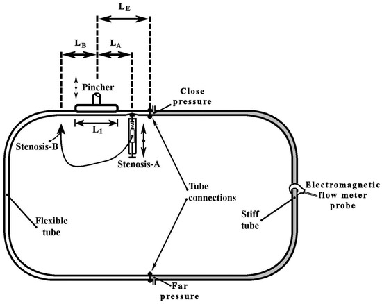
Figure 1.
Experimental rig.
2.2. Time-Dependent Stenosis Device
The innovative feature of this work is the introduction of a device to the valveless pump system which enhances the net flow rate through a time-dependent stenosis (see Figure 2). In Figure 2, each component is depicted with a certain number (nr). The device consisted of a compression spring (spring constant 2.5 N/mm, 43 mm long, see Figure 2a, nr 6), one edge of which was attached to a regulating screw (Figure 2a, nr 8) and the other edge to a half-cylindrical piece of Ertalon (diameter 22 mm, length 18 mm, see Figure 2, nr 3). The latter was always in contact with the flexible tube (Figure 2, nr 5) causing a local time-dependent tube stenosis (Figure 2b,c) by compressing it against a stationary transparent Plexiglas flat plate (Figure 2a,b, nr 4). The minimum cross-sectional area of the stenosis changed with a frequency equal to the frequency of the pump pincher (as a result of the applied unsteady fluid pressure), whereas its time mean value depended on both the fluid pressure and the pretension of the spring.
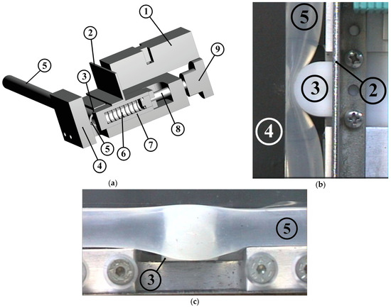
Figure 2.
Stenosis device: (a) 3-D drawing, (1) inductive sensor for distance measurement, (2) metallic plate attached to the oscillating half-cylindrical piece, (3) half-cylindrical piece of Ertalon, (4) stationary Plexiglas plate, (5) flexible tube, (6) compression spring, (7) spring case, (8) regulating screw, (9) screw handle meter. Details of the half-cylindrical piece compressing the tube: (b) viewed from above, (c) viewed from the side.
Preliminary tests revealed that the flow rate could be increased only if the stenosis was time dependent and its opening (smallest width of the tube shown in Figure 2b) was a small portion of the tube diameter (smaller than 3 mm, namely, smaller than 25% of the tube inner diameter). As a result, when the frequency of the pincher increased, the pretension of the spring had to be increased as well (by moving the spring’s one end by the screw) in order to retain small stenosis openings. Otherwise, the elevated fluid pressure (due to the inertia of the fluid and the reflection of the pressure waves [12]) pushed the spring back and the stenosis opening became large enough to not influence the flow rate. The selection of the above spring constant was based on the fluid force magnitude. More particularly, considering that the gauge pressure reached values as high as 100 kPa and given the fact that the half-cylindrical piece was in contact with the flexible tube for an angle of about 90°, the maximum applied force (under static conditions) was estimated to be 27.9 N for a pressure of 100 kPa. The latter force could be counterbalanced by the spring when it was compressed by a length of 11.1 mm or roughly 50% of its total available compression length. With regard to the opening of the stenosis, this was recorded by an inductive sensor (IA8-MIK-13, Pepperl + Fuchs, Mannheim, Germany) of an analogue output 300 mV/mm which measured the distance of the sensor from a metallic plate attached to the oscillating half-cylindrical piece (Figure 2, nr 2).
The flow rate augmentation by the proposed device was attributed to the locally imposed time-dependent hydraulic losses as a result of the time variable shape of the stenosis. As explained in more detail in the following paragraphs, the augmentation of the net flow rate is a matter of coordination between the motion of the pincher and the opening/closing of the stenosis.
2.3. Flexible Tube Properties
The flexible tube of the valveless pump was a peroxide cured silicon tube with a wall thickness of 1 mm and inner diameter D = 12 mm. In order to estimate the ratio of the tube volume change to pressure change , namely, (, 1 mL of water was injected into the hydraulic loop and the caused pressure elevation was recorded. This was repeated at various gauge pressures of the hydraulic loop in the interval −20 mmHg to 500 mmHg. For gauge pressures above 50 mmHg, it was found that the injected 1 mL of water increased the internal pressure by 24.5 ± 1.2 mmHg so that essentially the ratio was constant for the above pressure range. However, for lower pressures, the tube compliance was progressively increased so that at zero gauge pressure, the ratio was 1 mL/15.2 mmHg, and at −20 mmHg it was 1 mL/8.7 mmHg.
With regard to the tube’s Young’s modulus E, this is given by the formula (see Horeman and Noordergraaf [16]):
where vol is the flexible tube volume and is the tube inner radius to thickness ratio. Considering that the tube inner diameter was 12 mm at zero gauge pressure (undeformed tube state) and the volume of the flexible tube was 104 mL, the corresponding E = 2.38 MPa. Since the pressure varied in time above and below the ambient pressure, the Young’s modulus is expected to have taken higher as well as lower values than the above, respectively.
2.4. Compression Amplitude
The performance of the valveless pump was examined for various so-called compression ratios defined as:
where is the minimum tube cross-sectional area under the pincher, and the tube undeformed area. could be varied by changing the eccentricity of a rod (Figure 3, nr 3) which connected a crank (Figure 3, nr 2) with the oscillating flat plate of the pincher (Figure 3, nr 4) and by vertically moving a stationary horizontal plate (Figure 3, nr 5) upon which the tube was placed.
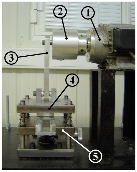
Figure 3.
Mechanism of compression ratio adjustment: (1) motor, (2) crank, (3) connecting rod, (4) oscillating flat plate, (5) stationary flat plate.
If L1 is the compressed length of the tube, the compression ratio can be written as:
where is the displaced water volume by the pincher. = 10.74 mL in the above formula is the undeformed volume of the tube part which is under the pincher. Therefore, for a given value, the two plates of the pincher were adjusted so that the displaced volume was equal to . The latter volume was estimated implicitly through the caused pressure increase Δp when the upper plate of the pincher was moved manually from its highest to its lowest position compressing the tube. Namely, knowing that and assuming that , the above pressure increase Δp corresponded to a displaced volume equal to Δp The value was determined by a trial-and-error procedure with an error which did not exceed 4%.
2.5. Measurement Equipment and Data Acquisition System
Regarding the used measurement equipment, this consisted of the following: (a) an electromagnetic flow meter (Carolina Medical FM501, Cary, NC, USA, with flat response up to 70 Hz) connected in the middle of the rigid tube (see Figure 1) which measured the time-dependent flow rate; (b) two pressure sensors (MILLAR, Houston, TX, USA, SPC-370 with flat response up to 10 kHz) which recorded the pressure at the two tube junctions. The pressure measured close to the pincher is named in the following paragraphs as ‘Close pressure’, and the other as ‘Far pressure’ (see Figure 1); (c) a wire sensor measuring the displacement of the pincher (Micro-Epsilon, Ortenburg, Germany, measuring range of 150 mm); and (d) a sensor measuring the opening of the stenosis (see above Section 2.2). The above five analogue signals were recorded with a sampling frequency of 600 Hz (about 60 times higher than the maximum examined frequency of the pincher) and for a minimum time interval of 20 s. The above two pressure signals were digitized by 24-bit A/D converters (MX440A, HBM, Darmstadt, Germany) and the other three signals by 16-bit A/D converters (SPIDER8, HBM, Darmstadt, Germany). Since the latter two acquisition systems were connected to different computers, a triggering system (based on a photodiode) was used to align all signals in time. Namely, a voltage pulse was sent to the two acquisition systems at an arbitrary time instant so that from then on, all recorded signals had the same time origin. Note that the data recording normally started 10 s after the beginning of each measurement to avoid transient phenomena.
2.6. Measurement Uncertainties
The uncertainty in the measured quantities in this work for a confidence level of 95% was as follows: flow rate: ±1.6%, pressure: ±3.3%, stenosis width: ±3.8%, pincher displacement: ±2.1%.
3. Results
The performance of the new flow control spring device was examined mainly for four values, namely, 38%, 49%, 65% and 75%, for an initial gauge pressure of 50 mmHg and pinching frequencies in the interval 5 Hz to 11 Hz, in which a local peak of the time mean flow rate appeared. The time mean flow rate, in the case that the stenosis was not used, is shown in Figure 4 for the above four values as a function of the pinching frequency. The net flow direction was from the pincher to the closer tube connection with peak flow rates of 0.25 L/min, 0.53 L/min, 1.57 L/min and 2.5 L/min, with increasing values and pinching frequencies close to 9.8 Hz. A similar behavior was documented in a previous work of this group (Manopoulos et al. [12]) in which the flexible tube was a silicon rubber platinum cured tube and the flow maxima appeared between 9 Hz and 11 Hz (close to the hydraulic loop resonance frequency).
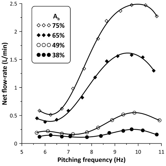
Figure 4.
Net flow rate versus pinching frequency for four values: 38%, 49%, 65% and 75% without stenosis.
When the stenosis was introduced in the hydraulic loop at either side of the pincher, its influence on the flow rate became progressively stronger with reducing values and smaller distances of the stenosis from the pincher. Due to space limitations, the closest distance of the stenosis from the middle of the pincher was 180 mm (Figure 1, LA = LB = 180 mm) from which all measurements were undertaken, following a trial-and-error procedure. Namely, for each pinching frequency, the regulating screw of the spring device (Figure 2, nr 8) was tightened or loosened in small steps aimed at flow rate maximization. The result of this procedure on the flow rate is depicted in Figure 5. When the stenosis was located close to the tubes’ connection (denoted Stenosis-A, see Figure 1), the flow rate was clockwise, in contrast with when the stenosis was located at the other side of the pincher (Stenosis-B, see Figure 1) where it was counterclockwise; therefore, the recorded flow rate signals are of opposite sign. In order to facilitate comparisons, the flow rate graphs presented in Figure 5 are in absolute values.
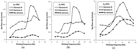
Figure 5.
Net flow rate versus pinching frequency with and without stenosis: (a) Ab = 38%, (b) Ab = 49%, (c) Ab = 65%.
The peak net flow rate values are shown for each value in Table 1, as well as their ratios to those without a stenosis RQ where:
with Qmax being the maximum net flow rate with the stenosis present, and Qomax the maximum net flow rate without the stenosis. It is interesting to notice that the influence of the stenosis became stronger with reducing values, so that for , the flow rate peak was 720% of the corresponding non-stenosis case when Stenosis-A was used, and 500% if Stenosis-B was used. It is also noteworthy to mention that Stenosis-A enhanced the flow rate at higher frequencies, in contrast with Stenosis-B which was more effective at lower frequencies. Analysis of the recorded data revealed that the presence of the stenosis did not alter the pinching frequency at which the net flow rate maximized (see Figure 5).
RQ = Qmax/Qomax

Table 1.
Peak flow rates and flow rate ratios.
Figure 6 shows, for the maximum flow rate case and the time variation in nondimensional form (t/T), where T is the period of oscillation, of each stenosis neck width (in mm) along with the pincher displacement (in cm). During tube compression by the pincher (notice that in this phase, the signal of the pincher displacement in Figure 6 was reduced) Stenosis-A was open, with its neck being about 1.8 mm wide, whereas during decompression it was almost closed, its width being 0.15 mm. In contrast, the width of the Stenosis-B neck varied between 0.4 mm and 1.3 mm, reaching its peak value at the end of the compression stage of the tube. Therefore, the larger flow rate of Stenosis-A for the examined case might be attributed to its better synchronization with the pincher motion. Namely, since Stenosis-A was open during the compression stage of the tube, the fluid passed through it more easily in contrast with decompression, where the stenosis was almost closed. As a result, the flow became unidirectional and the net flow rate was elevated.
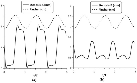
Figure 6.
Pincher displacement and stenosis width versus time at maximum net flow rate for Ab = 38%: (a) Stenosis-A, (b): Stenosis-B.
However, the above synchronization did not occur for all frequencies. A typical example of lack of synchronization between the stenosis opening and pincher motion is depicted in Figure 7, for and a pinching frequency of 8.15 Hz. Namely, Stenosis-A was practically open all the time (see Figure 7a), exhibiting two local maximum widths (at the beginning and at the end of the tube compression phase) resulting in a smaller flow rate (about 60%) compared with Stenosis-B. The latter stenosis seemed to work more effectively for this particular frequency (see Figure 7b) as well as for lower frequencies (see Figure 5), opening during the compression phase and closing during decompression.
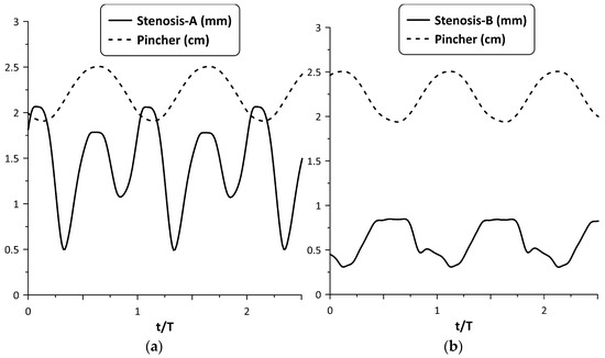
Figure 7.
Pincher displacement and stenosis width versus time at pinching frequency 8.15 Hz and = 38%: (a) Stenosis-A, (b) Stenosis-B.
The oscillation of the stenosis was a result of two opposing unsteady forces, that of the fluid pressure and the reaction of the spring. As shown in a previous work (Manopoulos et al. [12]), the pressure time variation at a given point in the hydraulic loop is affected mainly by the reflected pressure waves at the tube junctions, emanating from the pincher. By inserting a stenosis in the loop, the flow field becomes apparently more complex. Figure 8 shows the pressure time series at the two tube junctions along with the displacement of the pincher and the stenosis width for Stenosis-A and B at maximum flow rate and . In this case, during tube compression and when Stenosis-A was present, both pressure signals exhibited a peak at the end of this stage, almost simultaneously, in contrast with Stenosis-B, in which the pressure at the furthest tube junction had a phase lag. The different pressure time variations for the two stenosis cases affected their opening and finally the net flow rate. Moreover, compared with the pressure variation of the non-stenosis case, Stenosis-A seemed to affect the pressure less, in contrast with Stenosis-B which reduced the pressure amplitudes and caused the pressure signals to have fewer fluctuations.
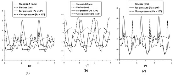
Figure 8.
Pincher displacement, stenosis width and pressures at the tube junctions versus time at maximum net flow rate and Ab = 38%: (a) Stenosis-A, (b) Stenosis-B, (c) no stenosis.
Similar behavior was observed for larger compression ratios. For example, Stenosis-A oscillation is depicted in Figure 9, for = 49% and 65% at the flow peak case. Despite the larger pressure amplitudes of the latter two cases, the tube neck width varied again in the range zero to 2 mm, such as for = 38% (as a result of the increased spring pretension), opening during compression and closing during decompression.
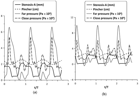
Figure 9.
Pincher displacement, Stenosis-A width and pressures at the tube junctions versus time at maximum net flow rate for (a) = 49%, and (b) = 65%.
Although the Stenosis-A oscillation for = 65% seems to be ideal, since it is open when the tube is compressed and occluded when it is decompressed, the flow rate enhancement as a percentage basis was smaller compared with the lower cases. It should be added that for = 75%, it was found that the flow rate increased only for very few pinching frequencies with a maximum change not exceeding 150%, whereas in other frequencies, the flow rate was reduced. Therefore, it is clear that the stenosis did not work effectively at high values. The same conclusion is drawn from Figure 5, in which it is shown that for = 65% and for Stenosis-B, the flow rate for high frequencies was smaller than that without the stenosis.
The flow rate enhancement in the examined configuration is a complex phenomenon. In addition to the coordination of the pincher and the stenosis motion mentioned above, it is the opening of the stenosis itself which also influences the flow rate. In this respect, the following experiment was conducted: the pinching frequency was kept constant at 6 Hz for = 65% and the neck width of Stenosis-B was adjusted by loosening the screw of the spring device, starting from an almost tube occluded state. Twelve cases were examined (case 1 to case 12), the flow rate of which as well as the extreme values of the stenosis neck width were recorded (see Figure 10). It is important to note that from case 1 to case 12, the adjusting screw of the spring was loosened and the amplitude of the stenosis width oscillation increased monotonically due to the smaller forces applied on the tube by the spring, whereas the flow rate increased up to case 9 and then dropped again. Therefore, it was concluded that the flow rate can take the same value for very different stenosis neck amplitudes. For example, cases 5 and 11 corresponded to almost the same flow rate, despite the fact that the stenosis amplitude of the first was ¼ compared with the second. Moreover, the extreme values of the neck width (maximum/minimum) also constituted a significant factor for flow control. For example, if the maximum neck width exceeded a certain limit (e.g., 2 mm or about 15% of the tube diameter), the caused hydraulic losses were apparently reduced so that the presence of the stenosis did not affect the flow rate. Similarly, if the minimum width of the neck during oscillation was not small enough so that the tube was not deeply occluded, again the presence of the stenosis was not significant for the flow rate influence. It is, thus, obvious that the flow in the stenosis is quite complex.
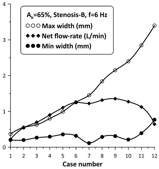
Figure 10.
Stenosis-B width (maximum/minimum) and net flow rate for Ab = 65%, and a pinching frequency of 6 Hz for 12 spring pretension values.
The tube neck width oscillation for the above 12 cases is depicted with solid lines in Figure 11 along with the motion of the pincher (shown with a dashed line). In this graph, when the pincher does not compress the tube, it is considered as zero displacement of the pincher. Based on Figure 11, the tube neck starts to enlarge in the middle of the compression stage of the tube and takes its maximum width before the end of this stage. Similarly, during decompression, the tube neck shrinks, normally performing a few smaller amplitude oscillations before the procedure is repeated again. The amplitude of the tube neck oscillation increases from case 1 to case 12, as presented in Figure 10.
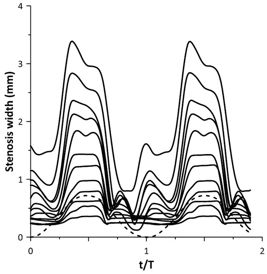
Figure 11.
Stenosis-B width versus time for the cases of Figure 10.
4. Discussion
It has been documented by numerous works, in the past, that when the pincher is far from the middle of the flexible tube length of a closed loop valveless pump (pincher asymmetric location), the net flow rate is elevated and it maximizes when the pinching frequency is close to a resonance frequency of the hydraulic loop. According to [7], the resonance frequency is equal to c/2L, where c is the Moens–Korteweg pressure wave speed given by the formula:
where ρ = 1079 kg/m3 (density of saline water of concentration 12.5% by weight, 20 °C) and = 0.49 is the Poisson’s ratio of the tube material. For the tube Young’s modulus E = 2.38 MPa (see Section 2.3), c = 15.6 m/s and the resonance frequency is 8.47 Hz. The maximization of the flow rate in this work appears at a higher frequency of about 9.8 Hz.
By increasing the pinching frequency, more than one local flow peak appears (due to more than one resonance frequency), of alternating sign. In other words, the net flow rate direction alternates as the frequency increases, becoming null when the direction changes from clockwise to counter-clockwise or vice versa. According to our previous work (Manopoulos et al. [12]) in which the first local peak was examined, it was found that the flow peak is a result of synchronization of the pincher motion and the streamwise pressure gradient.
In the present work, a convergent–divergent nozzle with oscillating walls was added in the loop, and, as expected, the flow field became more complex since pressure waves emanated from both the pincher and the stenosis. Moreover, the flow regime varied from laminar to transitional (with increasing pinching frequency) since the Reynolds number (Re = 4Q/νπD, with Q being the net flow rate and ν being the fluid kinematic viscosity) increased to 4700, whereas the unsteadiness expressed by the Womersley number α* (α* = 0.5 D (ω/ν)0.5, with ω being the cyclic frequency) reached 47. It is reminded that in [12], in which there was no stenosis in the valveless loop, Re took values of up to 7800 and α* to 48.
When the fluid is stationary, the neck width of the nozzle is a result of both the pretension of the spring (which is manually adjusted) and fluid pressure. However, when the pincher is set into motion, the pressure varies in time and space affecting the amplitude and shape of the oscillating walls of the stenosis. More particularly, when the pincher compresses the tube in a quasi-static way, the fluid pressure increases since a certain amount of fluid is expelled at both pincher sides causing an expansion of the flexible tube. For a circular tube of an isotropic and linear material, the pressure increase when its cross-sectional area expands from A0 to A, as given by the formula (see [11]):
According to (6), when the pincher compresses the tube under static conditions, the pressure will increase by 12 kPa for = 38%, 14.6 kPa for = 49% and 19.66 kPa for = 65%. During decompression, the pressure is reduced (due to the void caused by the pincher motion) and the fluid has the tendency to return to the pincher area. However, when increasing the pinching frequency, the pressure time variation at a given point is not easily predictable, having a phase lag or lead with respect to the pincher motion due to the inertia of the fluid and the pressure wave reflections at the tube junctions (due to the abrupt change of the tube Young’s modulus from soft to stiff tube). Due to pressure reflections, the pressure amplitude varies along the tube as a function of the ratio of the wavelength λ = c/f (where f is the pinching frequency) to the length L of the flexible tube (Zamir [17]). For example, if the latter ratio is 2, which occurs for f = 8.47 Hz, the amplitude of the pressure is zero at the middle of the flexible tube whereas at higher ratios (or lower pitching frequencies) this is spatially more uniform, taking the maximum value at the reflection site [16]. Therefore, the oscillation of the flexible tube walls is dependent on the spatial variation of pressure which in turn affects the flow rate. It is interesting to observe that the pressure time records shown in Figure 8 and Figure 9, despite their fluctuations, took higher values during the compression phase. Moreover, increasing from 38% to 65%, the pressure amplitude increased from 60 kPa to 100 kPa for Stenosis-A (see Figure 8 and Figure 9) or 66%, whereas under static conditions, as discussed above, the corresponding increase was from 12 kPa to 19.66 kPa, namely, 64%. Of course, the pressure amplitude is not related to the net flow rate. Comparing the pressure amplitudes with and without the stenosis for the maximum flow rate case of (see Figure 8a,c), although these were almost equal, the flow rate with the stenosis present was 7.2 times the flow rate without the stenosis. In fact, the pressure amplitude increased with the pitching frequency even when the net flow rate was null. Neglecting viscous forces and assuming a spatially uniform velocity field, Euler equations show that the streamwise pressure gradient counterbalances fluid inertia so that increasing pitching frequencies correspond to larger pressure amplitudes.
Based on the above, the opening/closing of the stenosis which depends on the local pressure variation in time is not always well synchronized with the motion of the pincher. By the term ‘well synchronized’, it is meant that when the pincher compresses the tube, the stenosis should open, allowing a certain fluid volume to pass though it, whereas during decompression, the stenosis should be occluded, hindering the backwards motion of the fluid. If this is the case, the fluid volume which is directed from the pincher towards the stenosis is greater than that which returns in each period, and as a result, the flow becomes unidirectional and the flow rate is augmented.
Based on a trial-and-error procedure, it was found that the flow rate enhancement occurred only when the nozzle walls were oscillating. In contrast, when the pretension of the spring was high enough so that the stenosis’s walls did not move, the flow rate was reduced. In the latter case, the stenosis behaved essentially as a valve which increased the hydraulic losses in the loop. On the other hand, even if the stenosis did oscillate but the time mean width of its neck was large enough, e.g., greater than 3 mm (more than 25% of the tube diameter), the flow rate remained unaffected due to the fact that the hydraulic losses of the stenosis were low during the whole period of oscillation. Therefore, the flow rate was augmented if the stenosis hydraulic losses were not constant during each period, increasing and decreasing suitably with the motion of the pincher. Of course, on increasing , the efficiency of the proposed device dropped as shown in Table 1. An explanation of this phenomenon can be as follows: at low values, the neccesary time variation of the hydraulic losses, as a prerequisite to obtain net flow rate, is imposed by the added stenosis, and not by the pincher which does not compress the tube enough. However, at higher values, the pincher plays two roles: (a) that of a mechanism which sets the fluid into motion (such as in small ) and (b) that of a moving stenosis which causes significant time-dependent hydraulic losses. Therefore, by introducing another stenosis in the loop, it seems that the added hydraulic losses reduce instead of increase the flow rate.
The flow field of a convergent–divergent stenosis has been the interest of many researchers not only because of relevant engineering applications but also due to blood flow in stenosed blood vessels, and of air in the air ducts of the respiratory system. The stenosis flow field characterized by flow separation in its divergent part becomes more complex when the inlet flow is unsteady (Young [18]), and even more complex if its walls are moving, such as in the present application. In the latter case, vortical structures dominate the flow (e.g., see Pedley [19], Anagnostopoulos and Mathioulakis [20]), and the hydraulic losses are dependent not only on the shape of the stenosis but on the inertia of the fluid as well. Moreover, the stenosis in the present hydraulic loop is a site of pressure wave reflections, making the problem harder to solve. More importantly, if the stenosis is deeply occluded, as occurs in several cases in the present work, computational fluid dynamics is not possible due to singularities which appear in the solution when the computational cells touch each other.
Compared with other flow enhancement devices appearing in the literature, being mainly taper tubes with stationary walls, the proposed stenosis is symmetric in the streamwise direction and its walls are moving. In the present work, each experiment was conducted by observing the flow rate signal time variation and turning (with small angles) the regulating screw of the spring so that the flow rate took its peak value for each pinching frequency. Apparently, the obtained flow rates could be higher if the procedure were automated, e.g., by employing a motor (servo or stepper) which would turn the screw according to the flow rate signal trends. Nevertheless, the selected experimental data revealed the feasibility of the new concept, demonstrating the significant flow enhancement at least at low compression ratios. In terms of the pump maximum volume efficiency, namely, the ratio of the net flow rate to the pincher fluid volume displaced per unit of time, it dropped from 77% (for = 38%) to 50% (for = 65%). In comparison, when there was no stenosis in the loop, the maximum volume efficiency increased from 11% ( = 38%) to 37% ( = 65%).
5. Conclusions
This experimental work examines a new concept of flow augmentation of a valveless closed loop pump consisting of a flexible and stiff tube through a time-dependent tube stenosis installed close to the pump’s pincher. The tube stenosis is formed by a semi-cylindrical surface which compresses the flexible tube by a linear compression spring of adjustable pretension, against a flat plate. Due to the time-dependent pressures, the stenosis walls oscillate with the pitching frequency without any external energy and its neck area is adjustable by the pretension of the spring. In contrast, all the used devices for valveless pump flow rate augmentation are taper tubes, the geometry of which do not change with the pinching frequency. Moreover, the proposed device is a convergent–divergent channel, symmetric in the streamwise direction with its hydraulic losses varying in time due to the change of its shape, whereas in the used taper tubes, the hydraulic losses vary due to the change of the flow direction. The pincher is asymmetrically located in the loop and the stenosis is either close to the flexible–stiff tube junction, called Stenosis-A, or at the other side of the pincher called Stenosis-B. The flowing medium was saline water, the compression ratio varied from 38% to 75% and the pinching frequency from 5 Hz to 11 Hz, in which a local peak of the net flow rate appeared. For an initial gauge pressure of 50 mmHg in the loop, the following conclusions are drawn:
- -
- Stenosis-A caused higher flow rates in the frequency range 8 Hz to 11 Hz, in which the flow rate maximizes, whereas Stenosis-B was more efficient at lower frequencies, also causing a reversal of the mean flow direction in the whole examined frequency range (5 Hz to 11 Hz). Namely, the net flow was directed from the pincher to each stenosis;
- -
- The percentage augmentation of the flow rate was elevated with reducing compression ratios reaching for = 38% a maximum of 720% of the non-stenosis flow rate when Stenosis-A was used, and 500% when Stenosis-B was used;
- -
- Flow rate augmentation is a result of appropriate synchronization of the stenosis opening with the tube compression by the pincher. Namely, the stenosis neck should enlarge during tube compression, whereas during decompression it should shrink or even become deeply occluded. In this way, the average flow becomes unidirectional and the net flow rate increases. However, the flow rate augmentation on a percentage basis was reduced with an increasing compression ratio, although in some cases the above-mentioned stenosis opening/closing conditions were satisfied. For high values, the hydraulic losses of the stenosis added to the elevated hydraulic losses at the pincher area cause a reduction instead of an increase in the flow rate;
- -
- Since the opening of the tube stenosis is a result of the applied forces of the fluid pressure and the opposing spring force, the flow rate enhancement is mainly a function of the pinching frequency, the compression ratio and the pretension of the spring for a given stenosis location in the hydraulic loop;Keeping the pinching frequency constant, a variation of the spring pretension influenced the net flow rate nonlinearly with the stenosis opening amplitude, showing the complex behavior of the flow through an unsteady stenosis;
- -
- Future work has to be undertaken (both numerically and experimentally) to provide further explanation of the efficiency of the proposed device operating under various conditions, bearing in mind that CFD is impossible to be used in cases where the stenosis is deeply occluded.
With regard to various applications of the proposed device, besides its use in closed loop valveless pumps, it can be also used in open loop valveless pumps moving liquids between tanks of different elevations. Moreover, a potential use of this device might be a blood flow booster in areas of the human body where the blood flow rate is abnormally low due to pathological reasons (ischemic episodes). The fact that this device does not need any external energy source is of paramount importance in this type of application. However, due to the above shown limitations of the device efficiency, a comprehensive study has to be undertaken for each specific case in the human artery tree to prove its value.
Author Contributions
Conceptualization, D.M.; methodology, C.M. and D.M.; software, D.M.; validation, C.M. and D.M.; formal analysis, D.M. and C.M.; investigation, C.M. and D.M.; data curation, D.M.; writing—original draft preparation, D.M. and C.M.; writing—review and editing, D.M. and C.M.; visualization, C.M. All authors have read and agreed to the published version of the manuscript.
Funding
This research received no external funding.
Conflicts of Interest
The authors declare no conflict of interest.
References
- Ozanam, M. De la circulation veineuse par influence. C. R. Acad. Sci. 1881, 93, 92–94. Available online: http://gallica.bnf.fr/ark:/12148/bpt6k3049g/f1.item.r=Ozanam (accessed on 7 August 2023).
- Liebau, G. Arterielle Pulsation und venöse Repulsation. Z. Für Gesamte Exp. Med. 1954, 123, 71–90. [Google Scholar] [CrossRef] [PubMed]
- Sarvazyan, N. Building Valveless Impedance Pumps from Biological Components: Progress and Challenges. Front. Physiol. 2022, 12, 770906. [Google Scholar] [CrossRef]
- Hickerson, A.I.; Gharib, M. On the resonance of a pliant tube as a mechanism for valveless pumping. J. Fluid Mech. 2006, 555, 141–148. [Google Scholar] [CrossRef]
- Bredow, H.J. Untersuchung eines ventillosen Pumpprinzips. For B VDI Z 1968, 7, 1–89. Available online: https://www.tib.eu/en/search/id/TIBKAT%3A196829372 (accessed on 7 August 2023).
- Rath, H.J.; Teipel, I. Der Fordereffekt in ventillosen, elastischen Leitungen. Z. Für Angew. Math. Phys. ZAMP 1978, 29, 123–133. [Google Scholar] [CrossRef]
- Avrahami, I.; Gharib, M. Computational studies of resonance wave pumping in compliant tubes. J. Fluid Mech. 2008, 608, 139–160. [Google Scholar] [CrossRef]
- Shin, S.J.; Sung, H.J. Three-dimensional simulation of a valveless pump. Int. J. Heat Fluid Flow 2010, 31, 942–951. [Google Scholar] [CrossRef]
- Kozlovsky, P.; Rosenfeld, M.; Jaffa, A.J.; Elad, D. Dimensionless analysis of valveless pumping in a thick-wall elastic tube: Application to the tubular embryonic heart. J. Biomech. 2015, 48, 1652–1661. [Google Scholar] [CrossRef] [PubMed]
- Garafolo, N.G.; Rich, B.C.; Cymbal, M.J. An Experimental Investigation of Closed-Loop Impedance Pumping in a Compliant, Elastic Tube Millistructure by Variation of Perturbation Location. J. Mech. Des. Vib. 2017, 5, 1–10. [Google Scholar] [CrossRef][Green Version]
- Manopoulos, C.G.; Mathioulakis, D.S.; Tsangaris, S.G. One-dimensional model of valveless pumping in a closed loop and a numerical solution. Phys. Fluids 2006, 18, 017106. [Google Scholar] [CrossRef]
- Manopoulos, C.; Tsangaris, S.; Mathioulakis, D. Net flow generation in closed-loop valveless pumping. Proc. Inst. Mech. Eng. Part C J. Mech. Eng. Sci. 2020, 234, 2126–2142. [Google Scholar] [CrossRef]
- Yan, Q.; Yin, Y.; Sun, W.; Fu, J. Advances in Valveless Piezoelectric Pumps. Appl. Sci. 2021, 11, 7061. [Google Scholar] [CrossRef]
- Yang, K.-S.; Chao, T.-F.; Chen, I.Y.; Wang, C.-C.; Shyu, J.-C. A Comparative Study of Nozzle/Diffuser Micropumps with Novel Valves. Molecules 2012, 17, 2178–2187. [Google Scholar] [CrossRef] [PubMed]
- Afrasiab, H.; Movahhedy, M.; Assempour, A. Proposal of a new design for valveless micropumps. Sci. Iran. 2011, 18, 1261–1266. [Google Scholar] [CrossRef]
- Horeman, H.W.; Noordergraaf, A. Numerical Evaluation of Volume Pulsations in Man I. The Basic Formula. Phys. Med. Biol. 1958, 3, 51–58. [Google Scholar] [CrossRef] [PubMed]
- Zamir, M. The Physics of Coronary Blood Flow; Springer: London, ON, Canada, 2005. [Google Scholar] [CrossRef]
- Young, D.F. Effect of a time-dependent stenosis on flow through a tube. J. Eng. Ind. 1968, 90, 248–254. [Google Scholar] [CrossRef]
- Pedley, T.J.; Stephanoff, K.D. Flow along a channel with a time-dependent indentation in one wall: The generation of vorticity waves. J. Fluid Mech. 1985, 160, 337–367. [Google Scholar] [CrossRef]
- Anagnostopoulos, J.; Mathioulakis, D.S. A flow study around a time-dependent 3-D asymmetric constriction. J. Fluid. Struct. 2004, 19, 49–62. [Google Scholar] [CrossRef]


Disclaimer/Publisher’s Note: The statements, opinions and data contained in all publications are solely those of the individual author(s) and contributor(s) and not of MDPI and/or the editor(s). MDPI and/or the editor(s) disclaim responsibility for any injury to people or property resulting from any ideas, methods, instructions or products referred to in the content. |
© 2023 by the authors. Licensee MDPI, Basel, Switzerland. This article is an open access article distributed under the terms and conditions of the Creative Commons Attribution (CC BY) license (https://creativecommons.org/licenses/by/4.0/).