Article

A Novel Design Concept of a Magnetorheological Fluid-Based Damper Utilizing the Porous Medium for Implementation in Small-Scale Applications

Mechatronics Group, Department of Mechanical Engineering, Technische Universitat Ilmenau, 98693 Ilmenau, Germany
*
Author to whom correspondence should be addressed.
Fluids 2023, 8(7), 203; https://doi.org/10.3390/fluids8070203
Submission received: 27 February 2023 / Revised: 16 June 2023 / Accepted: 22 June 2023 / Published: 7 July 2023
(This article belongs to the Special Issue The Recent Advances in Magnetorheological Fluids)

Abstract

:
Magnetorheological (MR) dampers have a virtue over conventional dampers, where their damping properties can be adjusted using a magnetic field. However, MR dampers have been barely implemented in small vibratory systems, in which the modal mass and stiffness are relatively small. This is due to two major reasons, namely its high parasitic damping force and big moving mass. When such an MR damper is installed in a small vibratory system, the system‘s default damping ratio is increased and therefore its dynamic is reduced. Here, a new concept of an MR damper utilizing the porous medium and shear operating mode together with an external non-moving electromagnet is proposed. This combination results in an MR damper with a low parasitic damping force and a small moving mass. For comparison purposes, a benchmark MR damper with comparable geometry is constructed. The proposed MR damper possesses a passive friction force that is 8× smaller and OFF-state passive viscous damping that is 10–20× smaller than the benchmark MR damper. An investigation of the proposed MR damper performance in a test vibratory system shows almost no reduction of the system dynamic. Therefore, this proposed MR damper configuration can be suitable for applications in small vibratory systems.

1. Introduction

Magnetorheological (MR) fluid-based dampers have adjustable damping properties due to changes in their fluidic behavior using a magnetic field [1,2]. The adjustability of the MR dampers is a virtue over conventional dampers, in which a vibratory system can be dampened optimally. Until now, MR dampers have been commercially used in several large-scale applications [3], such as in the automotive industry to increase ride comfort [4,5] and in civil engineering to make buildings or bridges able to withstand earthquakes and strong winds [6,7], replacing conventional hydraulic dampers. Despite its virtue in damping technology, the MR dampers have been barely implemented for small applications, for example for applications where the force operating range is smaller than 100 N. This is due to two major reasons:
  • Parasitic damping force. Parasitic damping force is the damping that cannot be eliminated. This damping is caused by the viscosity of the fluid and the damper sealing. Utilizing the MR fluid as the damper medium means that there will be an interaction between the fluid and the mechanical parts of the damper. Due to MR fluid viscosity, there is a considerable amount of damping force due to the viscous effect of the fluid, especially in the sufficiently high-velocity region. The MR fluid also needs to be contained in a fluid chamber, whereby sealings are required. The sealing rubs the moving part of the damper, causing an extra dissipation through the friction force. Moreover, for an MR damper operated in flow mode, the sealings should be able to withstand the operating pressure, which therefore increases the friction force even further [8]. In small-scale applications, both the viscous and friction forces are not negligible.
  • Damper mass. The MR fluid requires an electromagnet to generate the magnetic field. In most commercial products of MR dampers, the damper takes the shape of a cylinder tube with a piston in it [9]. To make a compact design, the electromagnet is integrated directly into the piston which increases the moving mass. For a large-scale application, this additional mass is negligible, since in most cases, the vibrating mass is much bigger than the mass of the piston damper. However, in small-scale applications, this additional mass will change the dynamics of the vibratory system significantly.
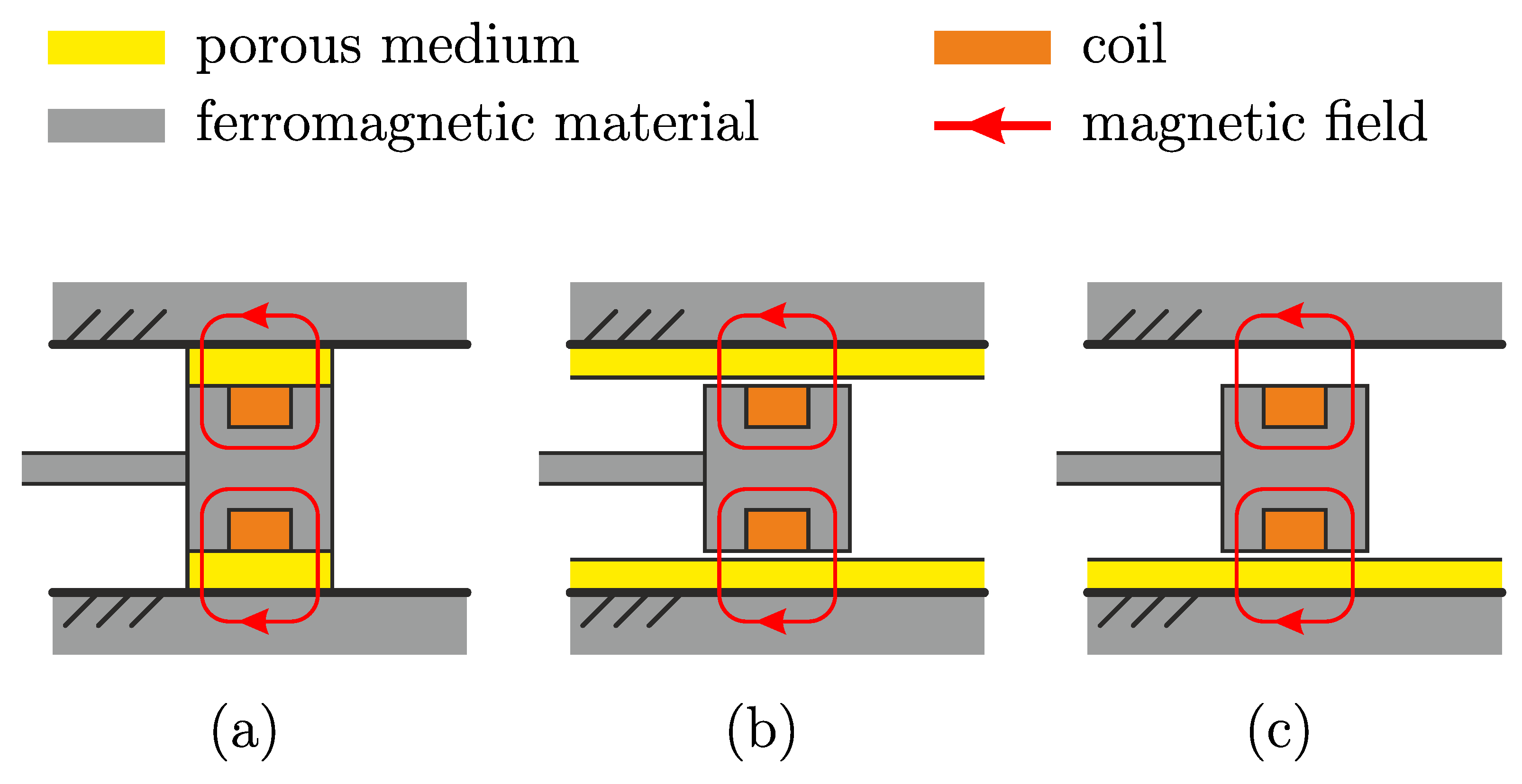
Addressing the two aforementioned problems for small-scale applications, several approaches have been proposed. In reducing the parasitic damping due to the friction force from the sealing, the shear operating mode is preferred instead of the flow mode. By using the shear mode, the sealing does not require withstanding high pressure. Therefore, the sealing can have less friction. As is reported in [10], the reduction of the friction force by using another sealing with less friction is proven to be advantageous in the application of a washing machine. Another approach is to use an elastic mechanism for the sealing, as is done in [11], (Figure 11) and [12]. This approach, however, limits the movement range of the damper, since the elastic mechanism possesses a small elongation range. Ref. [13] proposed similar ideas with a bellow mechanism, which results in a bigger movement range despite using the elastic mechanism. In reducing the parasitic damping due to the fluid viscous effect, a utilization of a porous medium was already proposed about two decades ago by different researchers. The idea of using a porous medium was proposed in [14,15], where polyurethane foam is saturated with the MR fluid and is attached to the piston. The principle sketch for this is depicted in Figure 1a. Using this principle, the MR fluid is contained by the porous medium and does not need to fill the entire fluid chamber. This results in a significant reduction of the MR fluid volume in the damper but did not eliminate the viscous effect.
To eliminate the viscous effect, the porous material should not have any contact with the moving part and should only act as a container for the MR fluid. Such an approach was done by [16] with a metal foam. It has been shown that in the presence of the magnetic field, the MR fluid is able to go out from the foam to make a contact with a surface that is placed not so far from the foam (up to 2 mm). Using this idea, an MR damper with a piston is proposed in [17,18,19], where the sponge is mounted at the housing wall over the circumference, and the electromagnet is attached to the moving piston. The principle sketch of this concept of MR damper is shown in Figure 1b. Using this principle, the MR fluid will only make a contact with the piston when the magnet is activated. However, due to gravitation, it is not clear how the MR fluid at the upper side of the damper could be absorbed back by the foam at the upper side of the housing after the magnetic field is deactivated. Therefore, the design of the MR damper in [20] would make more sense, where the metal foam is attached only to the lower part of the damper. The principle sketch of the MR damper is shown in Figure 1c, where in the absence of the magnetic field, the gravitation force will pull back the MR fluid to be contained back in the foam below the piston automatically. In summary, by using the foam as the container of the fluid and giving a small gap to the piston (moving part), the viscous effect during the OFF state can be eliminated. Thus, the MR effect is still able to be implemented, and therefore adjustable damping is still realizable. In reducing the damper’s moving mass, a simpler approach can be executed. Since the most weight was caused by the electromagnet at the piston, the mass and therefore its inertial effect can be significantly reduced by simply constructing the electromagnet at the outer side, as is done in [21], instead of directly at the piston (or the moving part). It has been shown in this work, that this approach results in a damper that can be implemented for small-scale applications in a form of a miniaturized landing gear. The drawback of this approach in general is that the electromagnet should be made big enough to cover the whole operating range of the damper.
In this paper, a new concept of an MR damper utilizing the porous medium and shear operating mode together with an external non-moving electromagnet is proposed. The porous medium will be placed only below the shearing plate with a certain gap to eliminate the viscous effect in the OFF state, similar to the concept in Figure 1c. The inertial effect of the shearing plate is minimized by constructing the electromagnet at the outer part of the fluid housing. Such a combination results in a damper with a low parasitic damping force and a small moving mass. The resulting force is measured for various applied current, velocity, and mechanical parameters to investigate the characteristic of the proposed MR damper. Additionally, to present the significance of the proposed concept, a shear mode-based MR damper with comparable geometry is constructed and used as the benchmark damper in this work. In comparison to the proposed MR damper configuration, the benchmark MR damper has no porous medium in its construction, representing the conventional MR damper. The characteristics and the performance of both dampers are tested in an experimental vibratory system. This investigation shows the importance of having a minimum parasitic damping force and small moving mass in small-scale applications. Therefore, the main contributions of this paper are:
  • An introduction of the novel MR damper concept including the investigation of its damping characteristic,
  • Damper characteristic comparison to a benchmark MR damper, representing a conventional MR damper with high parasitic damping, and
  • Performance comparison to the benchmark MR damper, showing the influences of parasitic damping and the inertial effect in a vibratory system, representing a small-scale application.
Theoretical background on the MR fluid, the shear operating mode, the electromagnets, and the influence of the damping in a vibratory system will be discussed in section two. This will give an overview of the working principle of the proposed MR damper and the understanding of the selection of mechanical parameters. The experimental setup for this work will be elaborated on in the third section. This consists of the design of the electromagnet, the structural configuration of both the benchmark MR damper and the new proposed foam MR damper, and the vibratory system used to test the performance of the MR dampers. Each measurement procedure together with its respective experimental results will be presented and discussed in the fourth section. This includes the identification of each MR damper and the performance comparison for both dampers in vibration damping of a vibratory system. In the fifth section, the whole work will be concluded and outlooks will be given.

2. Theoretical Background

In this section, a theoretical background of MR fluid, and the working principle of the shear operating mode are presented. The basic theory of the magnetic circuit is also included, whereby the magnetic field generation for the MR damper can be understood properly. In the last part of this section, the basic theory of vibration in a simple mass-spring-damper system is explained, which gives insight into how the damping influence the dynamics of a vibratory system.

2.1. Magnetorheological Fluid

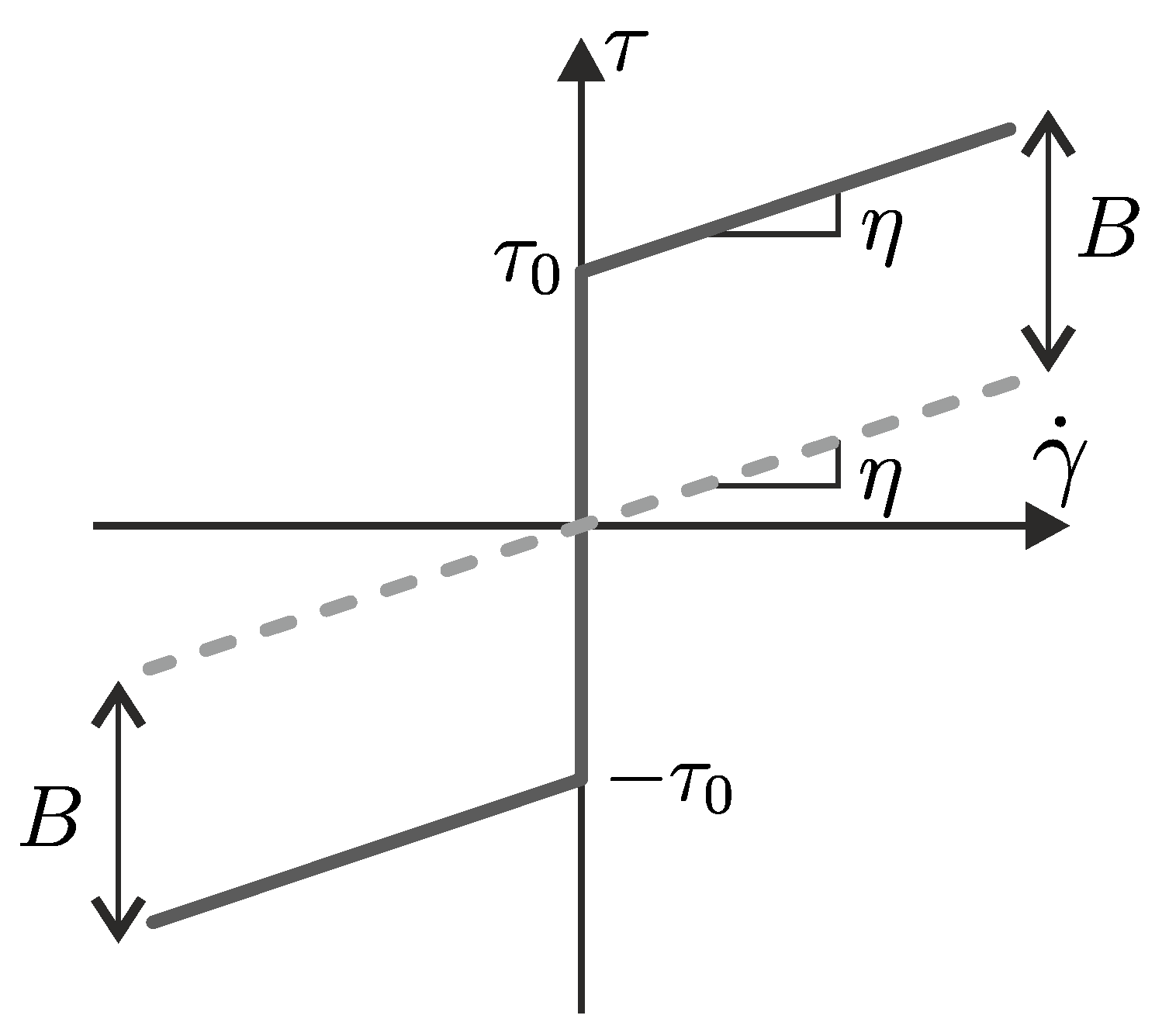
MR fluids are substances whose rheological behavior can be changed by the influence of magnetic fields. The rheological behavior of fluid material is determined by two physical quantities, namely, shear stress τ , and shear rate γ ˙ . For the MR fluids, these two physical quantities have the following relation:
τ = η b γ ˙ + τ 0 ( B ) sgn ( γ ˙ ) , if | τ | τ 0 G γ , if | τ | < τ 0
that follows the classical BINGHAM model. In this relation, η b is the dynamic viscosity, τ 0 is the yield stress due to the influence of the applied magnetic field B, G is the shear modulus, and γ is the shear. Figure 2 plots the shear stress-shear rate characteristic line of MR fluids.
The fluid that is used in this work is MR fluid AMT-SMARTEC + from Arus MR Tech in Chennai, India, whose properties are enlisted in Table 1. The relation between the applied magnetic field density B in T and the generated MR fluid yield stress τ 0 in kPa can be found in the datasheet of the fluid [22], where
τ 0 = 11.56 B 3 + 16.15 B 2 + 49.76 B
the yield stress is a third-order polynomial function of the applied magnetic field.

2.2. MR Fluid in Shear Operating Mode

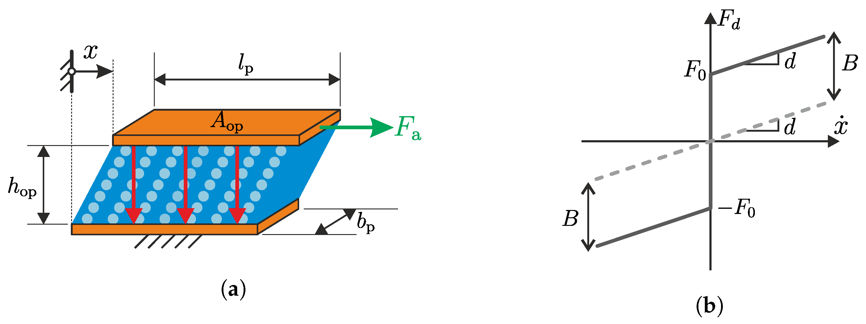
MR fluid can be operated in different operating modes [2,23]. In this work, the operating mode is most similar to the shear operating mode, in which the MR fluid is contained between two surfaces and sheared by the relative movement between those surfaces in the parallel direction. The sketch of the working principle for shear mode is displayed in Figure 3a.
As can be seen in the figure, the MR fluid between the plates is sticking to the plate surfaces. The shear stress τ from the fluid
τ = F d A op
is related to the resulted force F d by the operating area A op of the shearing surface. The operating area is defined by the area of the shear plate, in which the magnetic field is applied. When an external force is applied, that is big enough to result in a shear rate
γ ˙ = x ˙ h op
between the two plates, the resulted force F d due to the shearing can be derived from Equation (1), as in [24] (p. 191), [25].
F d ( B ) = η A op h op x ˙ F η + τ 0 ( B ) A op sgn ( x ˙ ) F r .
In this relation, h op is the gap between the shearing surfaces, and x ˙ is the relative velocity between the shearing surfaces. As is shown in Equation (5), the resulted damping force consists of two parts, namely, the damping force F η due to the viscous effect and the damping force F r due to the MR effect. The viscous force F η behaves similarly to a viscous damper, whose relation to the velocity is proportional to the damping constant d as the proportional factor; meanwhile, the force F r behaves similarly to a friction force, whose friction constant F 0 ( B ) depends on the applied field strength. This friction constant is called the blocking force F 0 which is defined as the required force to block the plate movement. By using the following relations for the damping constant and the blocking force
d = η A p h op and F 0 ( B ) = τ 0 ( B ) A op ,
the resulted force in Equation (5) can be written as
F d ( B ) = d x ˙ + F 0 ( B ) sgn ( x ˙ ) ,
whose characteristic line is depicted in Figure 3b. As can be seen in this figure, the form of the force-velocity characteristic line follows the form of the shear stress-shear rate characteristic of a BINGHAM fluid in Figure 2. It is to be noted from Equation (7), that despite the absence of the applied field ( B = 0 ), there still exists the aforementioned parasitic damping due to the viscous effect F η . The gap distance h op is inversely proportional to the resulted force. This means that by scaling down the gap distance h op , this viscous force F η will be drastically increased. It can be learned from this example, that scaling down the size to implement the MR damper for small-scale applications results in a bigger parasitic damping force due to the viscous effect.

2.3. Working Principle of the MR Dampers

The working principle of both the proposed and the benchmark MR damper is based on the aforementioned classical shear mode working principle. Depending on the material used in the damper, the configuration of the damper will be adjusted. The sketches of their working principle are depicted in Figure 4.
Figure 4a sketches the working principle of the proposed MR damper. The moving part of the damper and the MR fluid chamber are installed at the iron core gap, in which the magnetic field will be generated. The MR fluid is contained in the chamber, in which a porous medium, nickel foam, with a thickness t f is embedded. The chamber wall itself has a thickness of h w . The moving part of the damper is the shearing plate, which is shown in the figure using green color. The plate has a thickness of t p and is mounted on two linear guides, one on each end, allowing the plate to be moved only in the direction (x-direction) parallel to the foam surface. The linear guides are mounted at a certain height to position the plate to have an operating distance of h op to the foam surface, yet not touching the iron core of the electromagnet. In this way, the plate is separated by a distance h and does not have any contact with either the electromagnet or the foam during its operation. The OFF state figure presents the default state of the foam MR damper when there is no magnetic field is applied. In this state, the plate can be moved back and forth without rubbing the surface of the electromagnet or the foam. The only source of friction comes from the linear guides. As soon as the electromagnet is activated, a magnetic field is generated at the gap, symbolized ba he red arrows. The magnetic field pulled the MR fluid out from the foam, which created contact between the MR fluid and the lower surface of the shearing plate, as shown in the ON state figure. Depending on the magnitude of the applied magnetic field, the amount of the MR fluid pulled out from the foam and therefore the friction between the fluid and the shearing plate will vary. This is none other than the magnetorheological effect in shear mode, thus without the viscous effect of the fluid in its OFF state.
The working principle of the benchmark MR damper is depicted in Figure 4b. Similar to the proposed MR damper, the shearing plate and the MR fluid chamber are installed at the gap of the electromagnet. In comparison to the proposed foam MR damper, the fluid chamber is closed and filled with MR fluid. Therefore, sealings are required to contain the fluid inside the chamber. The shearing plate with a plate thickness t p , which is also shown in green, is inserted in the middle of the fluid chamber, resulting in two identical gap distance h op between the plate and the housing wall. In this way, the shearing plate has contact with the MR fluid on both the upper and the lower sides of the plate. The chamber wall of this damper has a thickness of h w . To ensure a parallel movement of the plate, the plates are also guided using two nonmagnetic linear guides, that are integrated directly at the fluid housing. In the OFF state figure, the movement of the plate in x-direction will shear the fluid on both sides of the shearing plate. As soon as the electromagnet is activated, a magnetic field is generated and the MR fluid particles possess stronger bonds, which will increase the force required to move the plate. This is the known rheological effect as explained in Section 2.2, which is presented by the ON state figure. Using this configuration, the benchmark MR damper can be used to represent the common MR damper, thus in a comparable size to the proposed MR damper.

2.4. Electromagnet and Its Magnetic Circuit

As can be learned from Equation (2), the yield strength τ 0 of the MR Fluid and therefore the blocking force F 0 depend on the magnetic flux density B. The bigger the magnetic flux density B, the bigger the blocking force F 0 . Therefore, it is generally aimed to have an optimal design of the electromagnet to achieve the biggest B possible. In this way, the damper will possess a big dynamic range, which is defined as the ratio between the force F d ( B = max ) by the maximum applied field and the force F d ( B = 0 ) by the absence of the magnetic field for the same operating velocity.
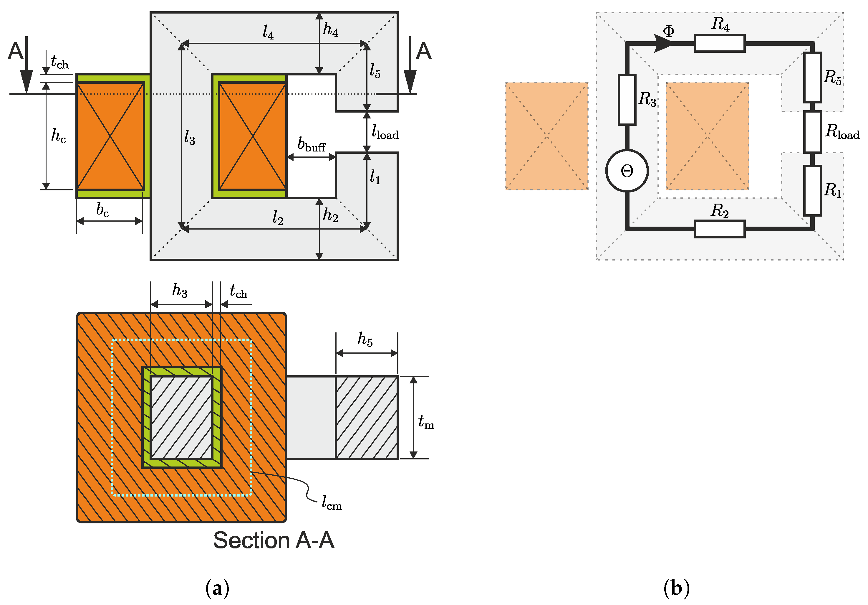
Figure 5a shows a sketch of a simple electromagnet configuration. It consists of an iron core, coil, and a gap at the iron core. The electromagnet is divided into several sections, based on the cross-section area of each section, and numbered accordingly. The gap that exists at the iron core is commonly counted as a single section and named as the load, in which the MR fluid will be placed. When a current is applied to the coil, magnetic flux density will be created at both the iron core and the gap. Since the magnetic permeability at the gap is (normally) different than the iron core, the magnetic flux density at the iron core and the gap will have also different magnitudes. Therefore, the magnetic flux density B in this gap will be the design criteria of the electromagnet.
In order to calculate the value of the B flowing through the electromagnet, the electromagnet can be represented as an electric circuit [26] (Page 23), as presented in Figure 5b. In this figure, it can be seen that the magnetomotive force Θ is analogous to the electrical voltage as the source of the circuit. The value of the magnetomotive force
Θ = N c I
depends on the number of coil winding N c and the applied electrical current I at the coil. The magnetic circuit in Figure 5b consists of only one circuit loop for the magnetic flux Φ . The resulting magnetic element law is:
Θ = Φ R m , tot ,
with the total magnetic resistance as:
R m , tot = j = 1 N s R m , j .
The total magnetic resistance follows from dividing the magnetic circuit into several sections. Each section is represented by one resistance symbol (see Figure 5b). They can be obtained by adding all the resistances, that are connected in series, with N s as the number of the sections in the magnetic circuit. Index j = 6 is chosen to be the section number for the load (see Figure 5a). The magnetic resistance from each section
R m , j = l j μ j A m , j
depends on the section length l, the material permeability μ at the section, and the area of the respective cross-section A m . The total magnetic resistance together with the magnetomotive force in Equation (8) determines the magnetic flux
Φ = Θ R m , tot ,
that flows in the magnetic circuit, whose behavior is analogous to the electric current that flows through the electrical circuit. Based on the cross-section area ( A m , 6 = A m , load ) at the load, the magnetic flux density at the gap (load section) can be calculated by the following relation
B 6 = Φ A m , 6 = Θ R m , tot A m , 6 .
From the calculated value B 6 , the yield stress τ 0 and therefore the blocking force F 0 can be estimated with the relation in Equations (2) and (6) respectively.

2.5. Damping in Vibratory System

Damping dissipates energy in a vibratory system. Therefore, it determines how fast vibration in the system can be decayed. The bigger the damping, the faster a vibration can be decayed in the vibratory system. However, too much damping in the system has also a drawback, where more actuation energy is required to generate a fast movement. In this sense, the concept of adaptable damping that is offered by MR dampers is advantageous, since the damping can be set to be minimal to allow a fast movement and can be set to be maximal to dissipate the vibration energy and therefore obtain the fastest decay time possible.

2.5.1. Damping of Viscous Damper

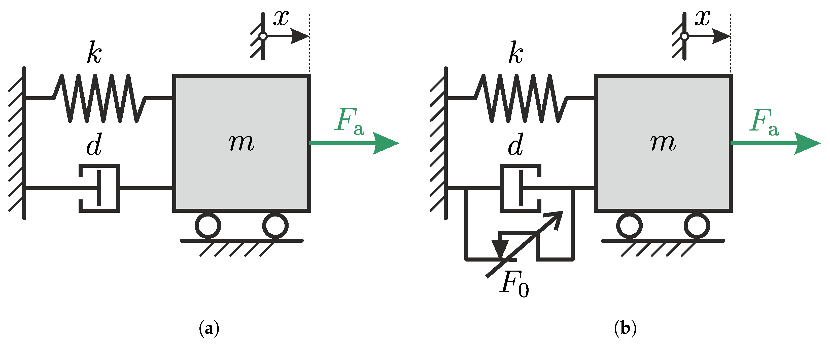
A simple vibratory system consisting of a mass, spring, and a viscous damper is depicted in Figure 6a.
In this system, m is the mass, k is the stiffness of the spring, and d is the damping constant of the viscous damper. When an external force F a is applied at the mass, the mass will move accordingly based on the dynamic of the system. The motion differential equation for this system can be written as follow
m x ¨ + d x ˙ + k x = F a .
This relation follows the standard form of second-order differential equation
x ¨ + 2 D ω 0 x ˙ + ω 0 2 x = ω 0 2 w
of a spring-mass-damper system, with ω 0 as the natural frequency and D as the dimensionless damping ratio of the system. By comparing both equations, the natural frequency ω 0 , the dimensionless damping ratio D and the static displacement w can be expressed as:
ω 0 = k m , D = d 2 k m , w = F a k .
This damping ratio D can be used to give an estimation of how big the damping is relative to the mass and the stiffness in the vibratory system.
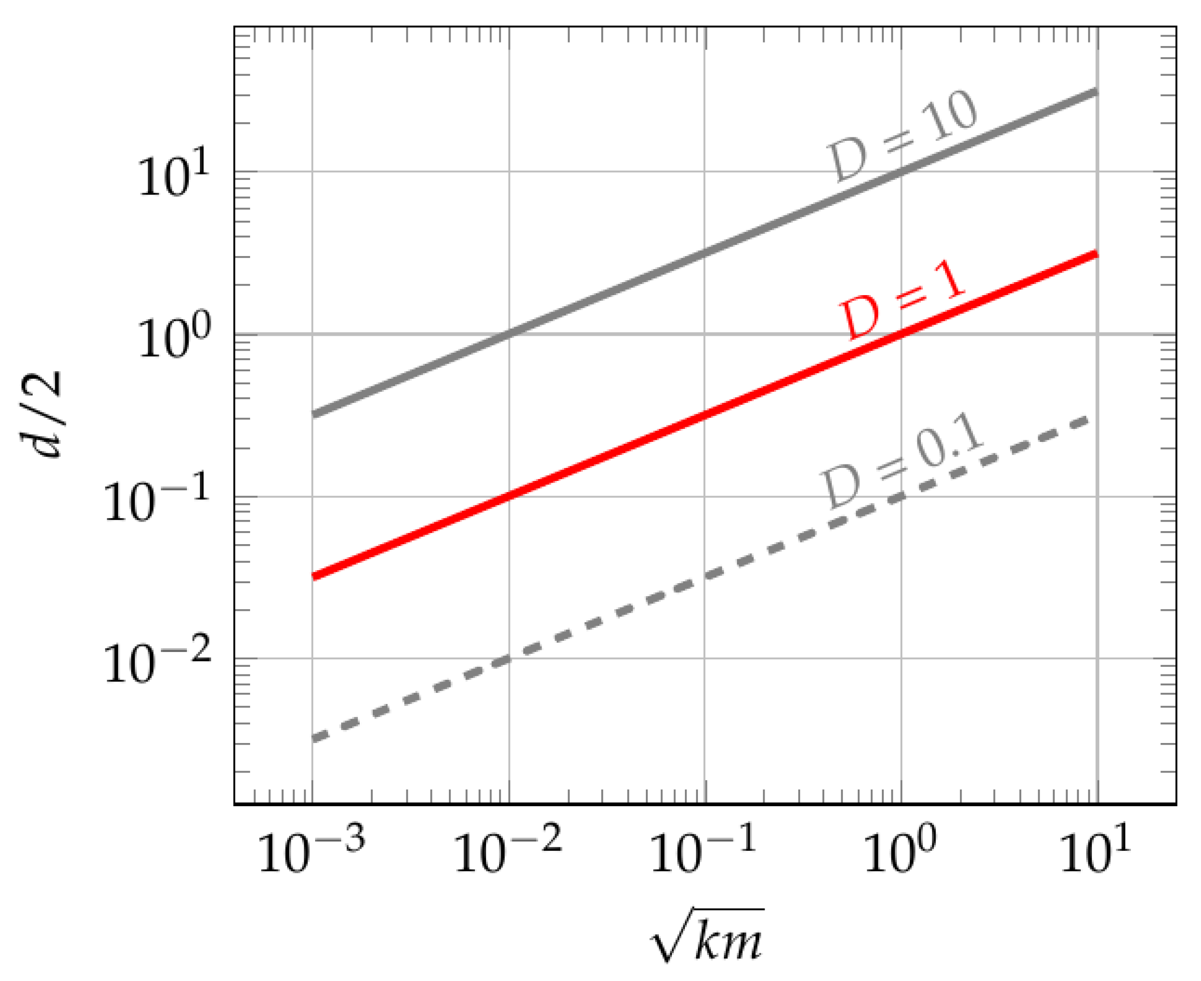
Figure 7 plots the the relation between the damping constant d and the mass-stiffness k m from Equation (16) for various damping ratio D.
As can be seen from the figure, for a vibratory system to operate the same value of damping ratio D, the smaller the product of modal mass m and modal stiffness k of the system, the smaller the modal damping constant d should be. Based on this reason, when a small vibratory system (a system with small m and k) requires to be operated with a small damping ratio, the damping constant of the damper should also be smaller.

2.5.2. Damping of MR Damper

A vibratory system with an MR damper has a configuration as sketched in Figure 6b. In comparison to the vibratory system with a conventional viscous damper, there exists a friction element as part of the damper (see explanation in Section 2.2). This friction element makes the system nonlinear and the differential equation of the system becomes:
m x ¨ + d x ˙ + F 0 ( B ) sgn ( x ˙ ) + k x = F a .
As can be seen from this equation, the form does not correspond to a standard form of the second-order differential equation in (15). Based on this reason, for a system with an MR damper, the damping ratio D can not be directly derived from the analytical solution.

2.5.3. Estimation of Damping Ratio

For a linear vibratory system, there is a method to estimate the damping ratio based on the frequency response of the system, as done in [27] (p. 53). For the vibratory system with a viscous damper (see Figure 6a), the transfer function of the system can be obtained by using the Laplace transformation for the differential equation in (15). This gives a transfer function
G ( s ) = x ( s ) w ( s ) = ω 0 2 s 2 + 2 D ω 0 s + ω 0 2
between the input w and displacement x of the mass as the output. The amplitude response of the transfer function in Equation (18) can be obtained by replacing the s = j Ω , resulting in:
G ( j Ω ) = x ^ ( j Ω ) w ^ ( j Ω ) = 1 1 β 2 + j 2 D β
with β = Ω ω 0 as the ratio between the operating frequency and the natural frequency. The amplitude of the transfer function is:
| G ( j Ω ) | = x ^ w ^ = V T
with V T as the amplification factor
V T = 1 ( 1 β 2 ) 2 + ( 2 D β ) 2 .
By plotting the amplification factor V T over the frequency ratio β , the frequency, in which the maximum amplitude of the amplification factor occurs, can be found. This is done by solving the frequency ratio from the condition where d V T d β = 0 , which results in
β max = 1 2 D 2 .
Inserting this to the second derivation of the amplification factor V T in Equation (21)
d 2 V T d β 2 ( β = β max ) = 1 2 D 2 2 D 2 ( D 2 1 ) D 2 D 4
always results in a negative value for 0 D ( 2 ) 1 . This is an evidence that the solution in Equation (22) is the maximum value of the amplification factor function. The maximum amplification of the transfer function is defined to be the quality factor Q,
Q = V T ( β max ) = 1 2 D 1 2 D 2
as done in [27] (p. 52), which can be calculated by inserting the maximum frequency ratio β max in the amplification factor function in Equation (21). Using this factor Q, the damping ratio D of the system can be roughly estimated. It is to be noted from this method, that Equation (24) is only valid for a damping ratio up to D = 1 2 0.707 . A greater value of the damping ratio will result in an amplitude response without any peak.
As mentioned before, since the damping ratio of the vibratory system with an MR damper can not be obtained analytically, the relation of the quality factor Q in Equation (24) will be used. When the friction constant (blocking force) F 0 and the damping constant d are known, Equation (17) describing the vibratory system in Figure 6b can be numerically solved and the amplitude response of the system can be obtained. Using the maximum value of the amplitude response and inserting it to Equation (24), an equivalent damping ratio D can be calculated. In this way, the damping ratio in the vibratory system with an MR damper for various magnitudes of applied current will be evaluated.

3. Experimental Setup

In this section, the design and the structural configuration of the MR dampers including its utilized magnetic circuit will be discussed. As was mentioned before, there will be two MR dampers used in this work. The first one is the MR damper, used as a benchmark. The second one is the proposed foam MR damper with shear operating mode. Since both dampers are using the same magnetic circuit, the magnetic circuit design will be explained first. The description of both MR dampers will be explained afterward. In the last part of this section, the configuration of the vibratory system used to test the dampers’ performance is presented.

3.1. Design of the Magnetic Circuit

As was discussed before, the magnetic flux density B 6 in Equation (13) depends on the amount of the magnetomotive force Θ that can be generated by the coil (see Equation (13)). The maximal amount of the allowable magnetomotive force given in (8) is calculated according to
Θ max = J alw k Cu b c h c
and is limited by the size of the winding window of the coil b c × h c in Figure 5a, where J max is the allowable current density and k Cu is the winding factor [26] (Page 302). When the generated magnetomotive force Θ exceeds the amount of the allowable magnetomotive force ( Θ > Θ max ), the temperature of the coil will increase rapidly and cause the coil to be damaged. Therefore, the winding window should be at least big enough to accommodate the desired magnetomotive force.
To determine the winding window, the design is conducted with the following steps:
Step. 1
Determine the maximum blocking force F 0 .
In an MR damper, the blocking force is the only variable whose magnitude is controllable by varying the magnetic flux density. Therefore, its maximum value is the main criteria in designing an MR damper.
Step. 2
Determine the operating area A op (see Equation (3) and Figure 3a and Figure 5a).
In shear operating mode, the area of the plate can be used as another criteria in determining the size of the damper and the electromagnet. This operating area will be the area of the electromagnet cross-section at the load, where A op = A m , 6 . In order to achieve the desired results, saturation in any electromagnet section should be avoided. Therefore, the cross-section of all electromagnet sections is made equal in this work ( A m , j = A op for j = 1 to 6). This is done by setting the height of each cross-section to be equal ( h j = h m for j = 1 to 6). Therefore, A op = h m × t m .
Step. 3
Calculate the required yield stress τ 0 .
Based on the chosen blocking force and shearing plate area, the respective yield stress can be calculated with τ 0 = F 0 / A op .
Step. 4
Calculate the required magnetic flux density B 6 and its respective magnetic flux Φ .
The magnetic flux density B can be obtained by inverting Equation (2). Using the calculated flux density B 6 , the magnetic flux Φ can be found by using Equation (13).
Step. 5
Define the magnetic permeability.
The magnetic permeability should be defined for each section based on the material used in the section so that the magnetic resistance value can be calculated (see Equation (11)).
Step. 6
Calculate the required winding window b c × h c .
The size of the winding window will determine how big the dimension of the electromagnet. Therefore, the mechanical geometry of the electromagnet should be the function of the winding window parameters. For the electromagnet configuration in Figure 5a), the relation between the mechanical geometries and the winding window parameters are:
h j = h m , for j = 1 to 6
l 3 = h c + h m + 2 t ch ,
l 2 = l 4 = b c + h m + t ch + b buff ,
l 1 = 0.5 l 3 ,
l 5 = 0.5 l 3 l 6 ,
where t ch the thickness of the coil’s housing, and b buff is a buffer distance. The buffer is added, so that there is still some space between the coil and the damper, which can be used to install the required electronics. The winding window is found by inserting the relation in Equations (10) and (25) in Equation (12). The relation in Equations (27)–(30) should be inserted (10) to have the total magnetic resistance as a function of the winding window. Equation (12) need to be solved for the winding window parameter, with a relation of h c = 1.5 b c .
Step. 7
Calculate the size of the magnetic circuit.
After the size of the winding window is found, the length of each section in Equations (27)–(30) and therefore the size of the electromagnet can be calculated.
The calculated parameters from the previous design steps (Step. 1–Step. 7) are used to calculate the diameter of the wire used at the coil. This is done by using the density ρ warm of the wire for a chosen maximum operating temperature T max and the mean wire length l cm of one coil winding, whose relations are as follow:
ρ warm = ρ 20 1 + α ( T max 20 )
l cm = 2 h m + 2 t m + 4 b c + 8 t ch
where ρ 20 the wire density at temperature of 20 C and α the heat transfer coefficient. Using those two parameters together with the maximum operating voltage U max at the coil and the allowable magnetomotive force Θ alw , the diameter of the wire [26] (Page 303)
d Dr = 4 Θ alw ρ warm l cm π U max
can be calculated. All the parameters used in this work are listed in the Table A1.
As can be observed from the design procedure of the electromagnet, several conclusions can be drawn regarding the scaling down of the size of the electromagnet.
  • The smaller the magnet, the smaller the winding window ( b c × h c ).
  • The smaller the cross-section of the iron core ( h m × t m ), the higher the magnetic resistance (see Equation (11)).
A smaller winding window and a higher magnetic resistance results in a smaller magnetomotive force, and therefore a smaller magnetic flux density that can be generated at the load section. Moreover, if the flux leakage is considered [26], the smaller the magnet, the bigger the flux leakage, and therefore the smaller the generated magnetic flux density B. Considering these aspects, implementing MR fluid in small-scale applications is considered to be challenging.

3.2. MR Damper Foam

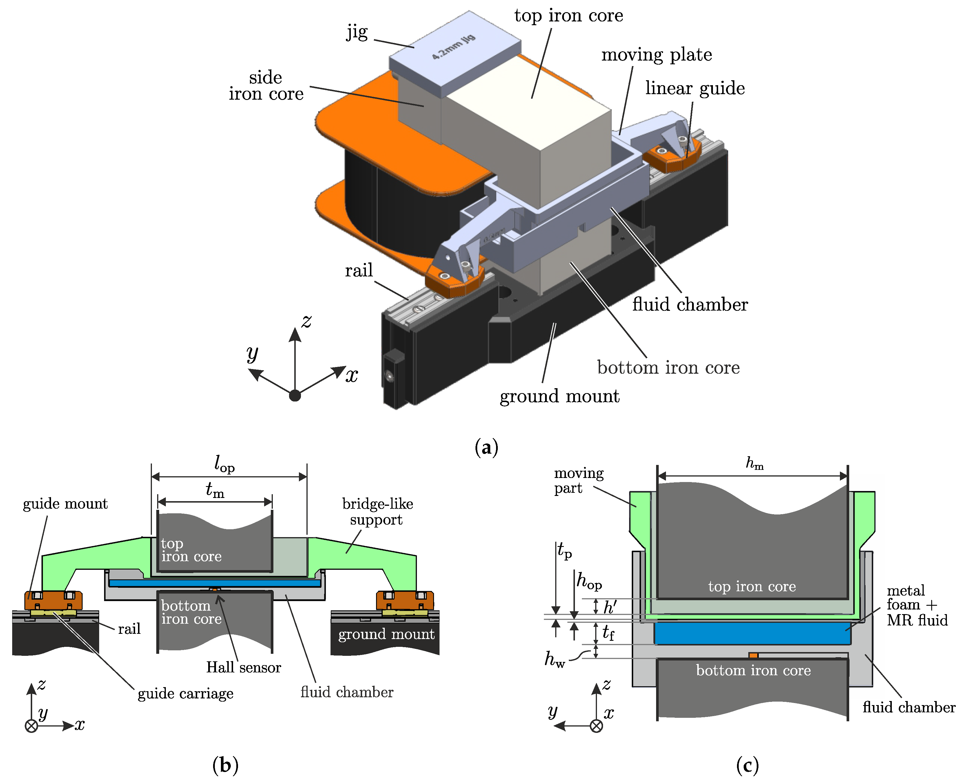
A prototype to realize the concept of the proposed foam MR damper utilizing the porous medium and shear operating mode is constructed in this work. In the load section of the electromagnet (see Figure 5a), the shearing mechanism is installed. Figure 4a depicts the CAD of the damper’s complete construction including the supporting figures to give an understanding of the working principle and construction details. The design is made to realize the in Figure 4a presented working principle.
The complete view of the structure is presented in Figure 8a. A spatially fixed x y z -Cartesian coordinate system is added to the figure to show the figure orientations. As can be seen in this figure, the electromagnet dominates the construction volume of the foam MR damper. The iron core consists of three parts, namely the top, side, and bottom iron core. The side iron core is made to be long enough so that the position of the top iron core and therefore the length of the load section is adjustable. To fix the length of the load section, a mechanical jig is plugged on the top of the side iron core. This jig serves as a stopper to fix the mounting position of the top iron core. In the load section of the electromagnet, a fluid chamber and the shearing plate are installed. The fluid chamber is mounted directly on the bottom iron core, meanwhile, the shearing plate is mounted to two linear guides. The linear guides will be guided by linear rails that are mounted to a single 3D-printed ground mount, which is fixed to the ground. In this way, the rails at both ends of the shearing plate can be set to be aligned, and therefore, the movement of the shearing plate can be guaranteed to exist in one direction only. The 3D printer used in this work is the Twotrees Saphire Plus, Shenzen, China, where polylactic acid (PLA) is used as material for the 3D-printed parts.
Figure 8b shows the cut section of the MR damper’s construction in the x z -plane at the middle of the magnetic circuit’s load section. The section lines are purposely removed to give a better presentation view. A 3D-printed fluid chamber is plugged into the lower part of the electromagnet. In this chamber, the nickel foam is fixed. The utilization of the nickel foam is inspired by [17], where a PPI (pores-per-inch) of 110 is chosen for this work. Between the nickel foam and the bottom iron core, a Hall sensor HE144T to measure the generated magnetic flux density is installed. This sensor is able to read a magnetic flux density of up to 1T. A 3D-printed shearing plate (shown in green) for the shear mode of the MR damper is made thin ( t p = 0.8 mm), so that the length of the load section can be minimized. However, since it is difficult to guide a thin plate due to the lack of stiffness, the plate is supported by a thick-bridge-like structure, which is 3D-printed together. Through this bridge-like structure, the damper is mounted to the linear guides. The linear guides consist of three parts, namely the guide mount, the guide carriage, and the rail. The guide mount is 3D-printed and serves as an adapter for the bridge-like structure to be attached to the guide carriage. The guide carriage and the rail are the drylin® N-carriage and the drylin® N-guide rail from IGUS GmbH in Cologne, Germany, respectively. They were chosen due to the low mass and friction. With this configuration, the moving part has enough stiffness to withstand the shearing forces during the operation. Figure 8c shows the cut section from another view (in y z -plane). Together with the view in Figure 8b, it can be seen that the moving part takes the shape of a box with one open side (top side). From this side, the top iron core is inserted and fixed to the side iron core after pushing it against the jig. The length l op of the moving part box and the fluid chamber limit the movement range of the MR damper. This design configuration allows the proposed foam MR-damper to have a travel distance of ±9 mm, which can be increased by using a longer housing and shearing plate. Additionally, Figure 8c shows the length l 6 of the load section for the electromagnet. For this proposed foam MR damper, the load section length will be (see Figure 4a for a better presentation):
l 6 , foam = h w + t f + h op + t p + h .
The calculated and chosen geometrical parameters of this proposed foam MR damper are listed in Table A2.

3.3. Benchmark MR Damper

The performance of the proposed MR damper needs to be compared with another MR damper, representing the conventional MR damper, but no metal foam is utilized. Therefore, a benchmark MR damper is built in this work to fulfill this purpose, whose dimension is about the same size as the proposed MR damper. In this way, the benchmark MR damper can be triggered using the same electromagnet. Not only the size of the damper, but also the operating area A op of the shearing plates of both dampers are made equal (see Table A2 and Table A3). A CAD of the benchmark damper’s complete construction including the supporting figures to give an understanding of the working principle and construction details is presented in Figure 9. The design is made to realize the working principle presented in Figure 4b. A spatially fixed x y z -Cartesian coordinate system is added to the figures to show the figure orientations. The presentation in this figure is made similar to the presentation of the foam MR damper (see Figure 8) so that the design and construction can be directly compared.
Figure 9a presents a complete view of the benchmark MR damper structure. As mentioned before, the same electromagnet as the one used in the proposed MR damper is used in the benchmark damper. For this damper, the fluid chamber is a closed chamber, in which the MR fluid is contained. The housing of the damper is 3D-printed. It is so constructed that the top and the bottom iron core can be directly plugged into the damper housing. In this way, the position of the damper is fixed relative to the electromagnet and no additional mount is needed. Based on this reason, the jig on the top part of the side iron core is not required. In this damper, non-magnetic rods made of brass are used as the connector between the damper and the vibratory system. In the fluid chamber, a shearing plate is inserted and attached to these rods. The movement of the rod will move the plate which makes the benchmark MR damper also be operated in shear operating mode.
Figure 9b shows the cut section of the construction of the aforementioned working principle in the x z -plane. This view gives the details of how the rod is mounted to the fluid chamber. As is shown in this figure, the shearing plate (shown in green) is connected to the connecting rods, one on each side. Each connecting rod is guided by a brass linear guide on each side, which is installed in the guide cap. These guides limit the shearing plate to be moved only along x-direction. On both sides of the fluid chamber, a sealing (shown in red) is installed. The guide cap is mounted via bolts to the housing, which indirectly presses the sealing to be fixed at the fluid chamber. Using this configuration, the sealing will not move during the damper operation. Figure 9c presents the cut section from the other perspective. It can be seen from this view that in the benchmark damper, a Hall sensor with the same specification as the foam MR damper is also installed. It can also be seen that both the fluid chamber and the shearing plate have a triangular edge on one of their sides. This is used as the plate guide, whereby the plate can be held parallel during the movement. In comparison to the proposed foam MR damper, the load section of this benchmark MR damper is defined to be (see Figure 4b for a better presentation):
l 6 , benchmark = 2 h w + 2 h op + t p .
The geometrical parameters of this damper are listed in Table A3.

3.4. Complete Experimental Setup with Vibratory System

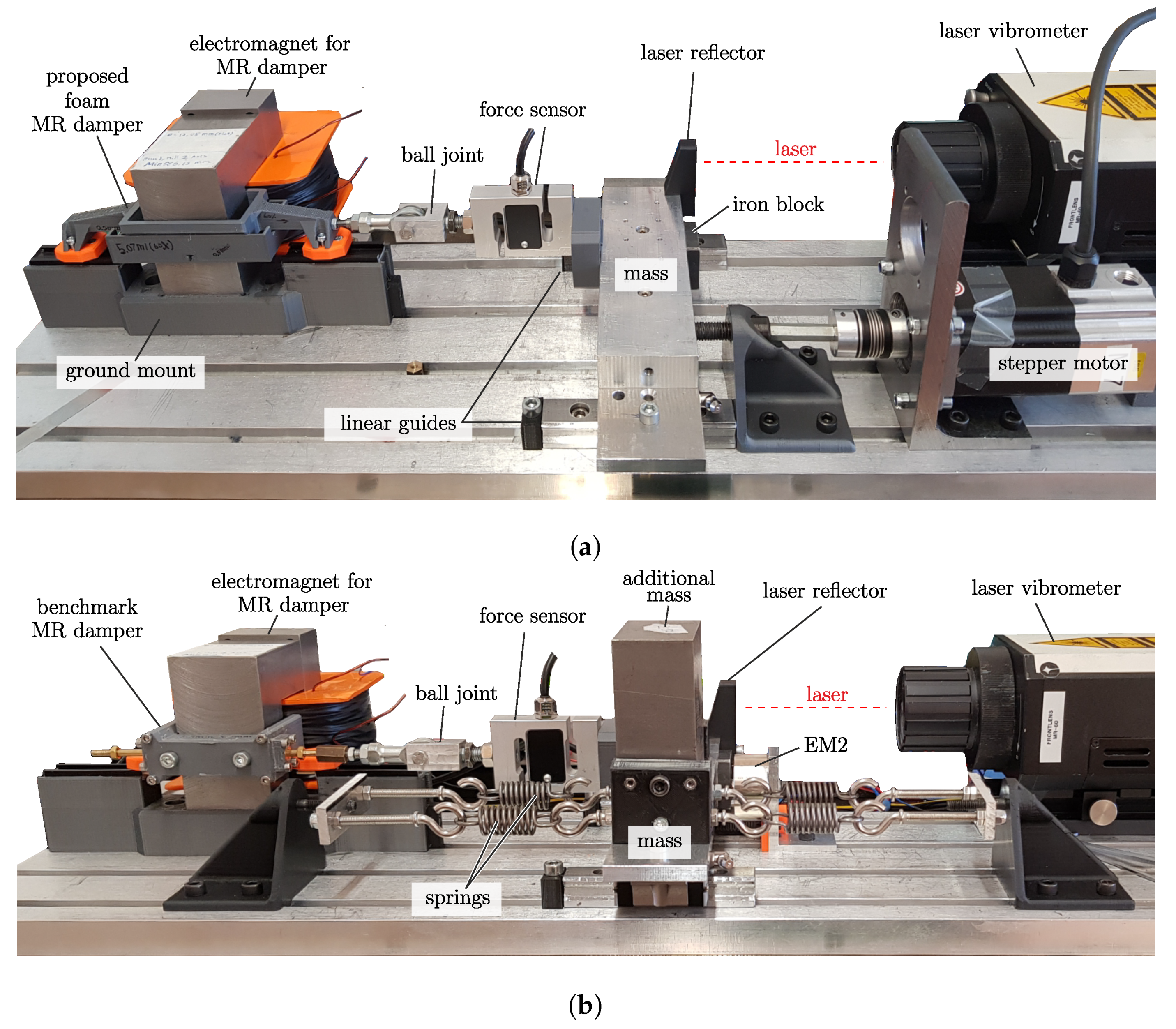
Both the proposed and the benchmark MR damper will be tested using a common experimental setup. The complete experimental setup is shown in Figure 10. The experimental setup is constructed such that parameter changes in the system can be done easily.
Figure 10a shows the setup configuration used to investigate the characteristic of the MR damper. It can be seen in this figure that all the components are mounted on one big T-slot plate, which allows an easy alignment. The damper plate is connected to a force sensor KAP-S from Angewandte System Technik GmbH, with a maximum measuring force of 100N via a ball joint. The ball joint is added to compensate for any misalignment between the damper and the force sensor and to ensure that the measured force is the force generated in the moving direction (x-direction). The force sensor is mounted to an aluminum block. This aluminum block acts as the moving mass and the platform to attach both the actuator and the sensors. The moving mass is guided by two linear guides to ensure that the movement exists only in one direction (x-direction). On the other side of the mass, a 3D-printed laser reflector is attached, whose surface is used as the measurement point for the movement of the mass. In the figure, a dashed red line is drawn to show the operating laser from the sensor is aligned with the reflector. Since the stiffness of the force sensor is high, the movement of the mass is assumed to be the movement of the MR damper. On the same side of the block, a stepper motor ECOSTEP 23S31-0650 from Jenaer Antriebstechnik GmbH in Jena, Germany, is attached. The stepper motor is connected to a bolt via a coupling, whereby its rotational movement can be used to drive the mass to move translationally. All the sensors, the MR damper, and the actuator (stepper motor) are connected to a data acquisition system, ADwin-Pro II made by Jäger Computergesteuerte Messtechnik GmbH in Lorsch, Germany, whereby both the measurement and the actuation can be synchronized. The ADwin-Pro II has 16 bit ADC/DAC channels and is operated with a sampling time of 300 ns in this work. Due to the large current requirement, the coil of the electromagnet is connected to a current source, whose current adjustment can be controlled via the ADwin-system as well. It is to be noted that this figure represents the case where the proposed foam MR damper is measured. The proposed foam MR damper can be easily replaced by the benchmark MR damper (as shown in Figure 10b); thus, the same setup configuration can be used to conduct the same experiment.
Figure 10b presents another setup configuration, in which the investigated MR damper is connected to a vibratory system. The configuration can be changed easily by removing the stepper motor and adding springs on both sides of the aluminum block. In changing the configuration, the force sensor, the ball joint, and the laser vibrometer do not require extra adjustment. As is also shown in this figure, an extra additional mass can be easily added to the aluminum block to vary the parameter of the vibratory system. By adding the additional mass, the total mass of the additional mass and the aluminum block will be the new mass for the vibratory system. For this configuration, an additional electromagnet is added to the system to generate an initial displacement of the moving mass. This electromagnet will be named EM2 from this point onward, to differentiate this electromagnet from the electromagnet used in the MR damper. In order to allow EM2 to pull the mass, an additional iron block is attached to the aluminum block (see Figure 10a). Upon deactivation of EM2, the mass is released from the predetermined initial displacement and vibrates freely until the vibration completely decays. It is to be noted, that this figure shows the case where the benchmark MR damper is installed. Nevertheless, the same configuration can be used to investigate the performance of the foam MR damper by swapping only the damper. It can also be seen through this figure that by the swapping of both dampers, the ground mount of the proposed foam MR damper did not need to be detached. This allows the experiment to be conducted under similar conditions that generate comparable experimental results. The parameters of the vibratory system are listed in Table A4.

4. Experimental Results

In this section, the results from the experiments will be presented. As mentioned before, there are two configurations of the experimental setup used for different investigation purposes (see Figure 10). The first results describe the characteristic of each MR damper. The experiment is conducted using the experiment configuration, shown in Figure 10a. The second part is the result from the experiment in a vibratory system. The experiment is conducted using the experiment configuration, shown in Figure 10b. The results of both configurations will be explained and discussed in this section to show the performance of both MR dampers.

4.1. Benchmark MR Damper

First, the measurement results displaying the characteristic of the benchmark MR damper are presented. In the experiments, the stepper motor is used to actuate the movement of the damper. The movement including the velocity of the damper will be measured by the vibrometer; meanwhile, the resulting force is measured by the attached force sensor. The generated movement is controlled so that the same movement can be repeated in the experiments. The measured forces are then plotted to their respective velocities. The measurement results including the comparison to the mathematical model are presented in Figure 11.
There are three group plots presented in Figure 11. The first one is the measurement results, which are plotted using the marks. The second one is the ideal mathematical model, which is plotted using dashed lines. The third one is the modified mathematical model, which is plotted using continuous solid lines. The same color is used for the plots with the same amount of applied current I. The ideal mathematical model is derived from Equation (7):
F d ( I ) = d x ˙ + F 0 ( I ) + F R sgn ( x ˙ ) ,
with F R being the friction constant for the friction due to the sealing, and d and F 0 are the theoretical damping constant and blocking force, respectively, whose values can be calculated using Equation (6). The theoretical damping constant should not vary since the operating area A op , operating gap distance h op and the viscosity η are constant parameters, as listed in Table A3. The theoretical blocking force F 0 varies, dependent on the magnetic field density yield stress B = B 6 at the load section. The magnetic field is inserted in Equation (2) to obtain the yield stress τ 0 and therefore the blocking force by multiplying it with the operating area A op . The magnetic field density B is the one measured by the integrated Hall sensor (see Figure 9c), whose measurement results are listed in Table 2.
The modified mathematical model
F d ( I ) = d ( I ) x ˙ + F 0 ( I ) + F R sgn ( x ˙ ) ,
is an extension of Equation (36), where the damping constant d ( I ) has a dependency on the applied current. For both mathematical models, the damper parameters are written as a function of applied current I instead of the magnetic field density B. This is done to give a proper comparison between the benchmark MR damper and the proposed foam MR dampers, since those dampers will have different operating magnetic field densities due to their different configurations.
As can be seen in Figure 11, the measurement results and the results from the ideal mathematical model (36) with calculated parameters do not fit together. For the condition when no magnetic field is applied ( I = 0 ), there exists no blocking force ( F 0 = 0 ). Therefore, the existing offset is the friction force F R from the sealing. As the velocity exists ( x ˙ 0 ), the measurement results show bigger forces F d than the one calculated from the ideal mathematical model. This shows that the damper has a higher damping constant d. When the magnetic field is applied ( I > 0 ), the blocking force F 0 is increasing as the current increases. It is, however, to be observed that as the current is applied, not only the damping constant d but also the blocking force F 0 from the measurement has higher values than the one calculated from the ideal mathematical model. The difference is suspected to be caused by the operating mode of the damper itself. First, even though the damper is planned to be operated in the shear mode, the damper structure is not exactly the one used in conventional shear mode. The shearing plate is not covering the whole operating area (Figure 3a), but it is shorter than the operating area of the magnetic field Figure 4b. Therefore, during its movement, the shearing plate not only shears the fluid between the plate and the housing but needs to oppose the solidified MRF along its path. Second, the side of the shearing plate has a flat surface, which causes an additional drag force when it is moving through the fluid. Since the damper is used only as a benchmark, the influences from those two effects on the measured results are not investigated further. Because of the discrepancies between the ideal mathematical model and the measurement results caused by the mentioned reasons, the benchmark MR damper characteristic is described using the modified mathematical model (37). For this mathematical model, the dampers parameters are fitted to the measurement results and the fitted parameters (d and F 0 ) are listed in Table 2. The parameters are fitted using the least mean square method, where the fitted lines should deliver the least difference to each respective set of experimental result. As can be seen in Figure 11, the modified mathematical model and the measurement results are in good agreement.
There are three things that need to be highlighted from the investigation. First, this benchmark MR damper was designed to operate using shear mode and have a comparable operating size to the proposed foam MR damper. As can be seen in the Table A2 and Table A3, this benchmark MR damper has an equal operating area with the proposed foam MR damper ( A op = 1500 mm 2 ) and similar operating gap h op . Therefore, the two MR dampers can be assumed to be comparable. Second, the shear operating mode is chosen for the benchmark MR damper to achieve the lowest parasitic force due to sealing possible. Since the sealing should not withstand any pressure in the fluid chamber, the sealing may have low friction constant, and therefore, the parasitic damping due to the sealing friction can be minimized. The smallest friction force achieved using this setup is measured to be 4 N (see Table 2). Third, some unknown effects caused the error between the mathematical model and the measurement results. It is also to be observed, that for higher applied current ( I 3 A), the force shows a shear thinning characteristic, which causes an increasing discrepancy between the mathematical model and the measurement results as the velocity is increased. However, these differences are not further investigated, since this MR damper is not the main focus of the work and will only be used as a benchmark in this work to give an estimation of how big the operating force can be generated for the chosen damper geometry. Therefore, the fitting of the model parameters is assumed to be sufficient to describe the characteristic of this benchmark MR damper.

4.2. Foam MR Damper

In this work, some damper parameters are varied in order to find the best design approach for the damper. For this purpose, the MR fluid filling ratio V FR and the operating gap h op of the proposed MR damper are varied. The MR fluid filling ratio V FR
V FR = V MRF V f
is defined to be the volume ratio of the MR fluid V MRF to the volume of the nickel foam V f (listed in Table A2). In this work, the tested MR filling ratio V FR will be 60%, 75%, and 90%. The filling ratio of 100% was not tested because the same volume of the MR fluid will not fit in the metal foam to be contained. The second varied mechanical parameter is the operating gap h op . The investigation is conducted to find the limiting air gap of the foam MR damper, which is defined by the gap in which the MR effect is still applicable. On one hand, if the gap is too small, there will be a possibility that the carrier fluid of the MR fluid will stay in contact with the shearing plate, even though no magnetic field is applied. This could happen especially for the 90% MR filling ratio due to the wetting effect of the fluid on the foam surface. This will increase the parasitic damping force due to the viscous effect, whose effect should be eliminated by the proposed structure. On the other hand, when the gap is too large, the MR fluid particles will not reach the shearing plate in its ON state. In this work, the investigated operating gaps are 0.5 mm, 1.0 mm, and 1.5 mm.
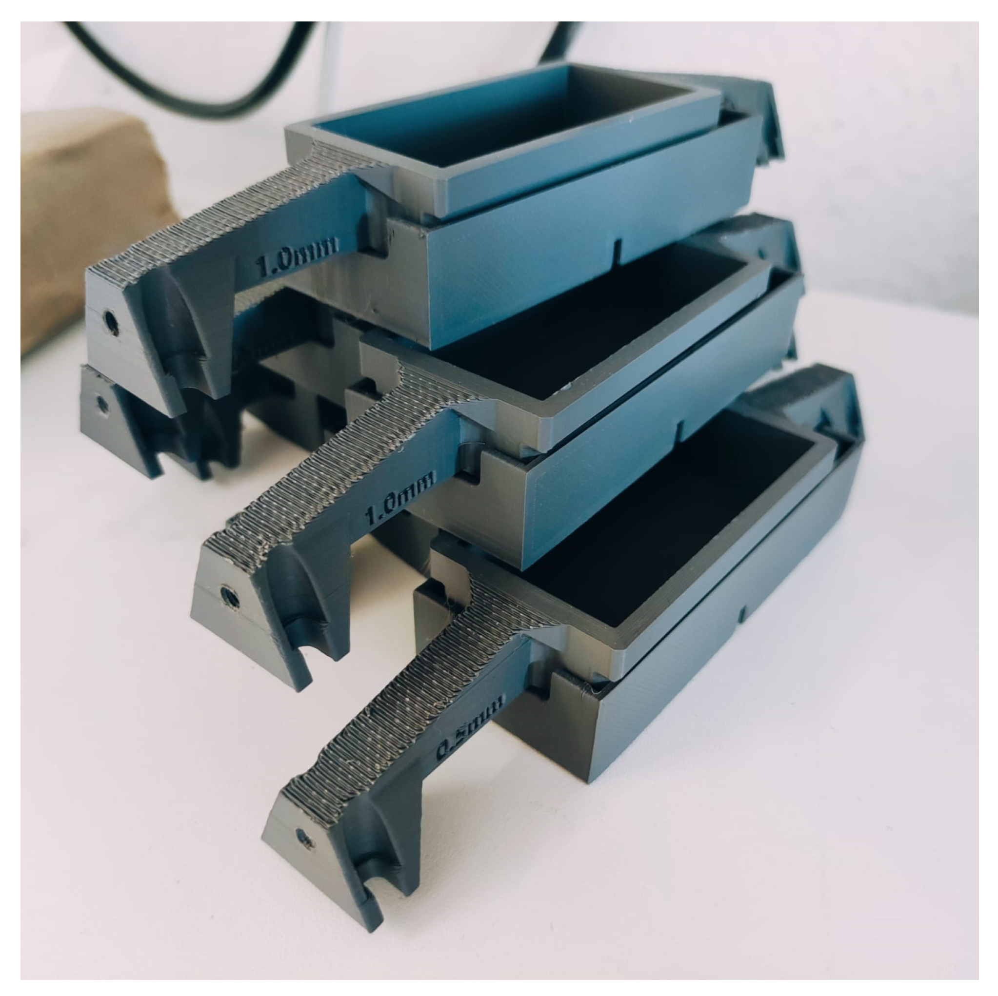
To perform this investigation, both the fluid chamber and the shearing plate are made multiple. Figure 12 depicts the multiple chamber-plate set, each for one investigated parameter set. Since both the chamber and the plate are 3D-printed, they can be manufactured equally despite having a complex structure. The measurement results to describe the characteristic of the proposed foam MR-dampers are presented in Figure 13.
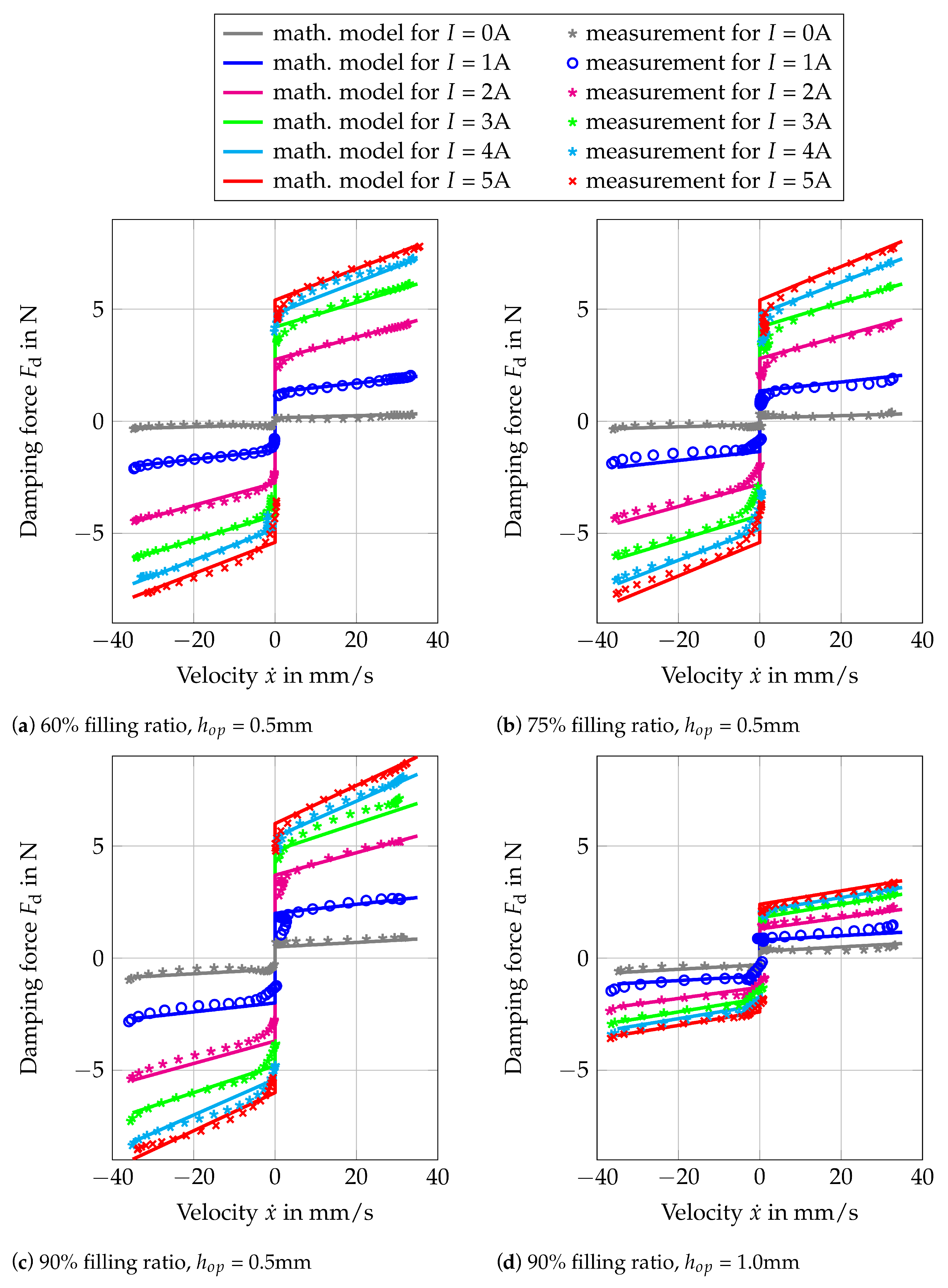
The measurement procedures are identical to the one conducted for the benchmark MR damper. It can be seen from the results that even though there is no contact between the shearing plate and the MR fluid in its OFF state, there still exists an offset in the force. This is caused by mechanical contact from the guides in the system. Moreover, it is to be expected that more MR particles are drawn out from the metal foam as the current increases. This might vary the damping constant d of the damper as well. Therefore, Equation (37) will be the suitable model for describing the damper characteristic. It is to be noted that no mathematical model describing the MR damper with foam structure has been proposed in the previous work [16,17,18]. In the same manner, as in the previous result presentation, the measurement results and the mathematical model are plotted using the marks and the continuous lines, respectively. The same color represents the same excitation current during the measurement. The mathematical model is the one from Equation (36), whose parameters are obtained by fitting them to the measurement results. All the fitted parameters are listed in Table 2. As can be seen in all four plots, the measurement and the mathematical model are in good agreement.
Figure 13a–c present the results for the investigated foam MR damper with operating gap h op of 0.5 mm, with MR filling ratio V FR of 60%, 75%, and 90% respectively. As can be seen from those three figures, the resulting force is approximately 10× smaller in comparison to the benchmark MR damper. This is despite the fact of having the same shear operating area and similar magnetic flux density for various applied currents (see Table 2). This is due to the reason that using this foam configuration in the MR damper, there will be fewer MR particles in the ON state, that have contact with the shearing plate during its operation. Therefore, the resulting force will be smaller as well. It can also be observed from these results that for an operating gap of 0.5 mm, the MR filling ratio has almost no influence on the force-velocity characteristic of the damper. A small increment of both damping constant and blocking force for various applied currents can be seen in Table 2 as the MR filling ratio is increased. Thus, the increment is considered to be insignificant. Another point to be observed is the parasitic damping due to the friction from the guides. Since there is no sealing mechanism required, the guides are the only friction source in the system. As listed in Table 2, the friction from the guides is small. For the three MR filling ratios, a friction constant of less than 0.5 N can be achieved. This is a big improvement in comparison to the sealing friction in the benchmark MR damper, which is 4 N. The other parasitic damping, which is caused by the viscous effect of the fluid in its OFF state is 10–20× smaller in comparison to the benchmark MR damper. This is due to the reason that the MR damper is designed to have no contact with both the metal foam and the MR fluid. However, by the MR filling ratio of 90%, it can be observed that there is an increment of the damping constant during its OFF state. This is suspected to be caused by the wetting effect of the fluid, which can not be absorbed fully by the metal foam.
Combining the combination of the investigated MR filling ratio and the operating gap, there are nine foam MR dampers in total to be investigated. Nevertheless, as can be seen in Figure 13, only the results of four representative foam MR dampers are presented. When the operating gap is increased to 1.0 mm, the parasitic damping effect due to the viscous effect (due to the wetting of the fluid) is decreased. However, the controllable blocking force due to the magnetorheological effect is drastically reduced as the consequence. This is shown in Figure 13d, where the total force is approximately reduced by half. It is obvious from the four presented results, that either a bigger operating gap ( h op > 0.5 mm) or less MR filling ratio will result in an even smaller force. This is the reason that the results of the foam MR damper with an operating gap of 1.5 mm and the foam MR damper with an operating gap of 1.0 mm with less MR filling ratio are not presented.
Despite having a small resulting force, the foam MR damper with 1.5 mm can be used to visualize the ON state of the proposed foam MR damper. By replacing one chamber wall with plexiglass and using a daily camera from a smartphone, the structure of the drawn-out MR particles can be seen. Figure 14 shows the picture of the ON state for different MR filling ratios with an operating gap of 1.5 mm.
The figures show how the MR particles are being drawn out from the foam when the magnetic field is applied. The particles built pillar-like structures between the shearing plate and the fluid chamber, parallel to the magnetic field direction. It is also to be observed, that more particles can be seen at a higher MR filling ratio.

4.3. MR Damper in Vibratory System

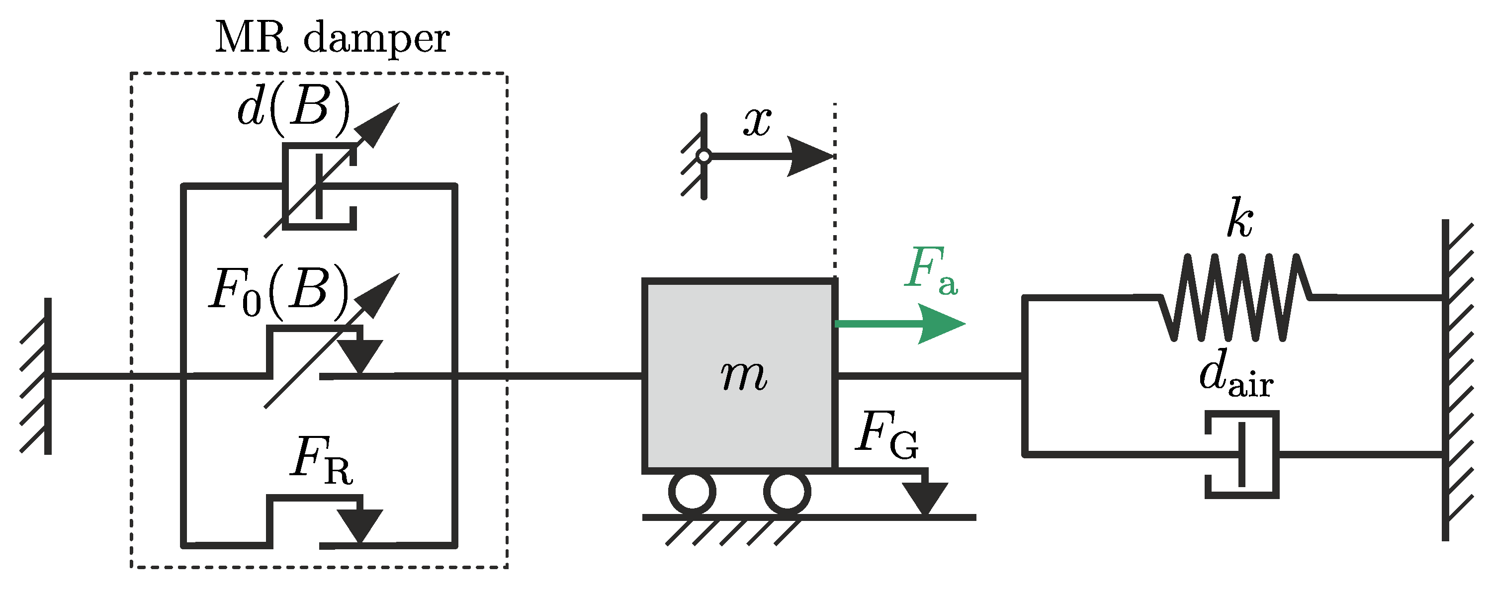
After investigating the characteristic of each MR damper, the MR dampers are tested in a vibratory system. The experiment is conducted using the experiment configuration, shown in Figure 10b. Based on the results obtained in the previous section, both the MR dampers have varying damping constant as the applied current varies. Moreover, there is additional friction from the linear guide of the vibrating mass itself. Therefore, the mechanical representation in Figure 6b does not represent the working principle of both MR dampers in the vibratory system. Figure 15 depicts the correct representation of the vibratory system, adapting the air damping d air and additional friction F G from the guides of the vibrating mass.
The vibratory system consists of a mass m and springs, with a total stiffness of k. The mass is guided to allow the resulting vibration to occur only along one axis. The friction from the guides of the vibrating mass has friction with friction constant of F G . Together with the springs, the MR damper will be attached to the mass, so that the damper and the spring have a parallel arrangement. The MR damper is represented as a parallel arrangement of a viscous damper element with a varying (symbolized by the diagonal arrow) damping constant d ( I ) , a friction element with varying friction constant F 0 ( I ) , and a friction element with fixed friction constant F R . This represents the damper mathematical model in Equation (37). Using this configuration, the whole vibratory system possesses the following differential equation:
m x ¨ + d tot x ˙ + F f , tot sgn ( x ˙ ) + k x = F a ,
d tot = d ( I ) + d air ,
F f , tot = F 0 ( I ) + F R + F G ,
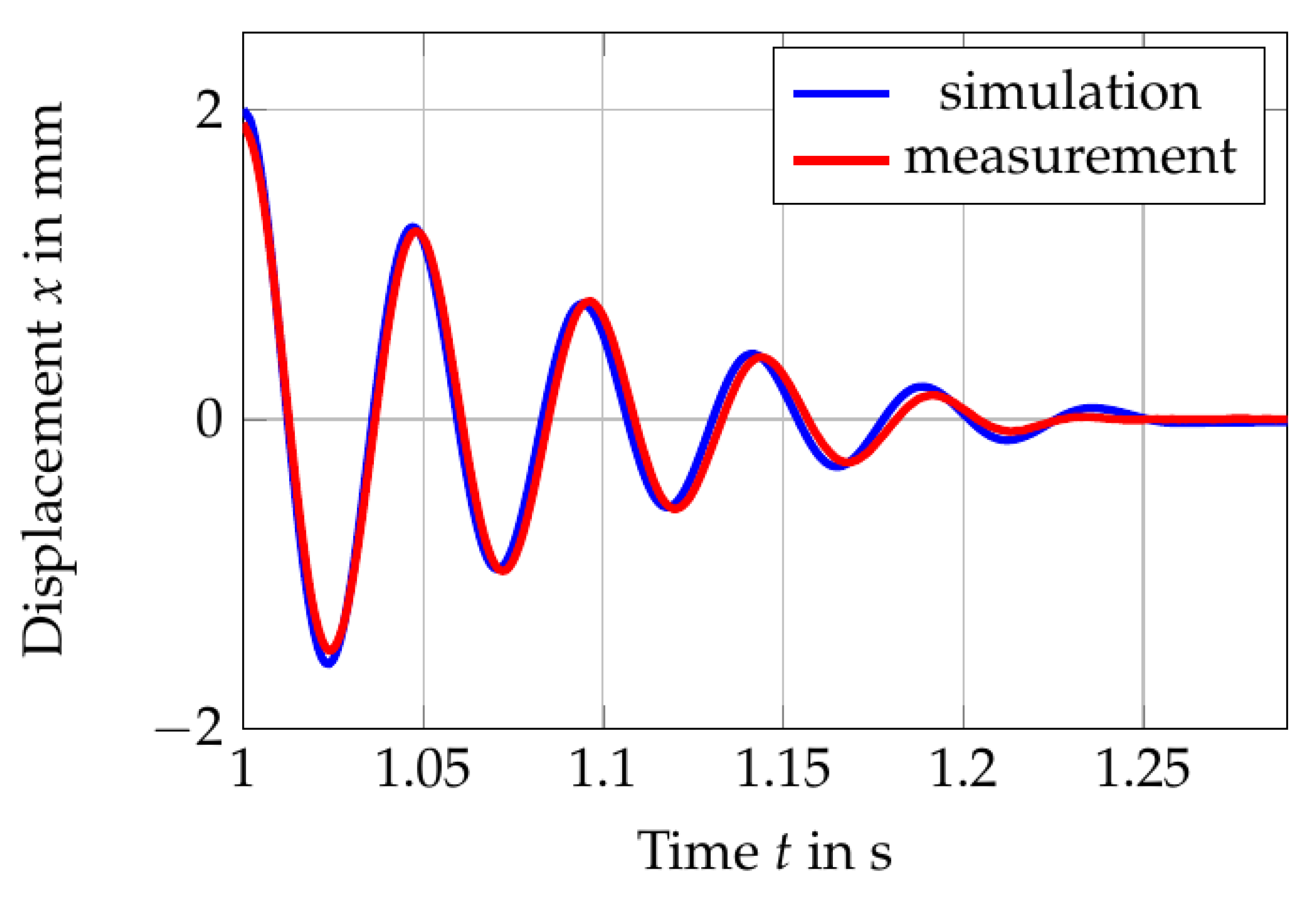
where all the damping and friction constant can be added together. The parameter of the proposed foam- and benchmark MR dampers have been identified in Section 4.1 and Section 4.2 give the value of the friction force F R due to the sealing or guide of the damper, viscous damping constant, d ( i ) and the blocking force F 0 ( i ) for different applied current conditions. The obtained parameters can be found in the Table 2. For the complete vibratory system, the other two parameters, namely, the friction constant F G from the guides of the moving mass and the damping constant d air from air need to be identified. This is done by fitting those parameters to the free vibration response of the vibrating mass when there is no damper is attached. Figure 16 depicts the comparison of the measured and simulated response, where SIMULINK from MATLAB2019b is used to solve the equations for non-linear system numerically.
The results in the figure are assumed to be in good agreement, with F G = 0.5 N and d air = 25.25 Ns/m. The fitted values of the friction constant F G and the damping constant d air are used to simulate the vibratory system with the configuration shown in Figure 15.

4.3.1. Free Vibration Behavior

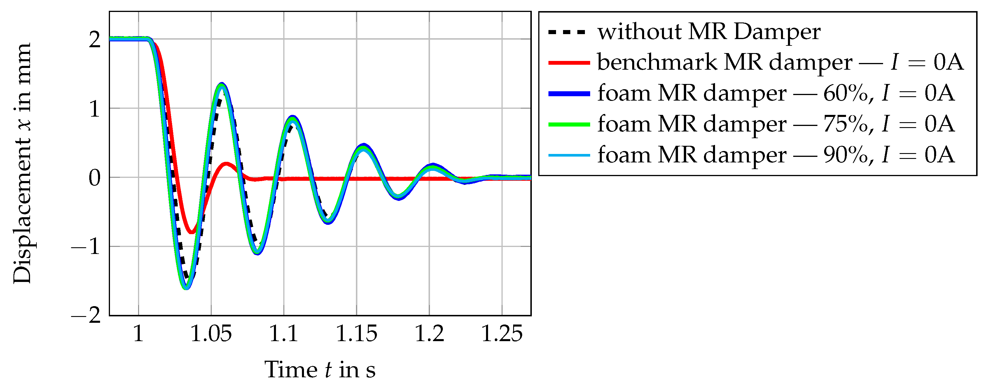
In this part of the investigation, the electromagnet EM2 is placed at a specified distance to the initial position of the mass. The mass is then pulled and the EM2 is activated, holding the mass using the magnetic force. The electromagnet of the MR damper is activated and the state of the MR fluid in the chamber is initialized. After the initialization process is done, the EM2 is deactivated. The mass vibrates freely due to the stiffness of the springs. The vibration of the mass is measured by the vibrometer. Based on the measurement results, the damping from the damper is then examined. The measurement results are presented in Figure 17 and Figure 18.
The results in Figure 17 show the comparison of the free vibration of the mass with and without the MR damper. As is shown in this figure, when there is no MR damper attached, the vibration decays after approximately 260 ms (after 5 periods of vibration), starting from the time when electromagnet B is deactivated. The damping in this state comes from the air and friction from the guides. As soon as the benchmark damper is attached, the decay time of the vibration reduced significantly to about 85ms, even without applying any current at the coil. This shows that the passive damping from the benchmark MR damper has added considerable damping in the system. In comparison to this, when the proposed foam MR damper is connected to the vibratory system, the decay time stays almost unchanged (about 260 ms). It can be concluded from this experiment that the proposed MR damper has a small amount of parasitic damping. In contrary, by only integrating the benchmark MR damper in the system, the damping has been increased by a significant amount.
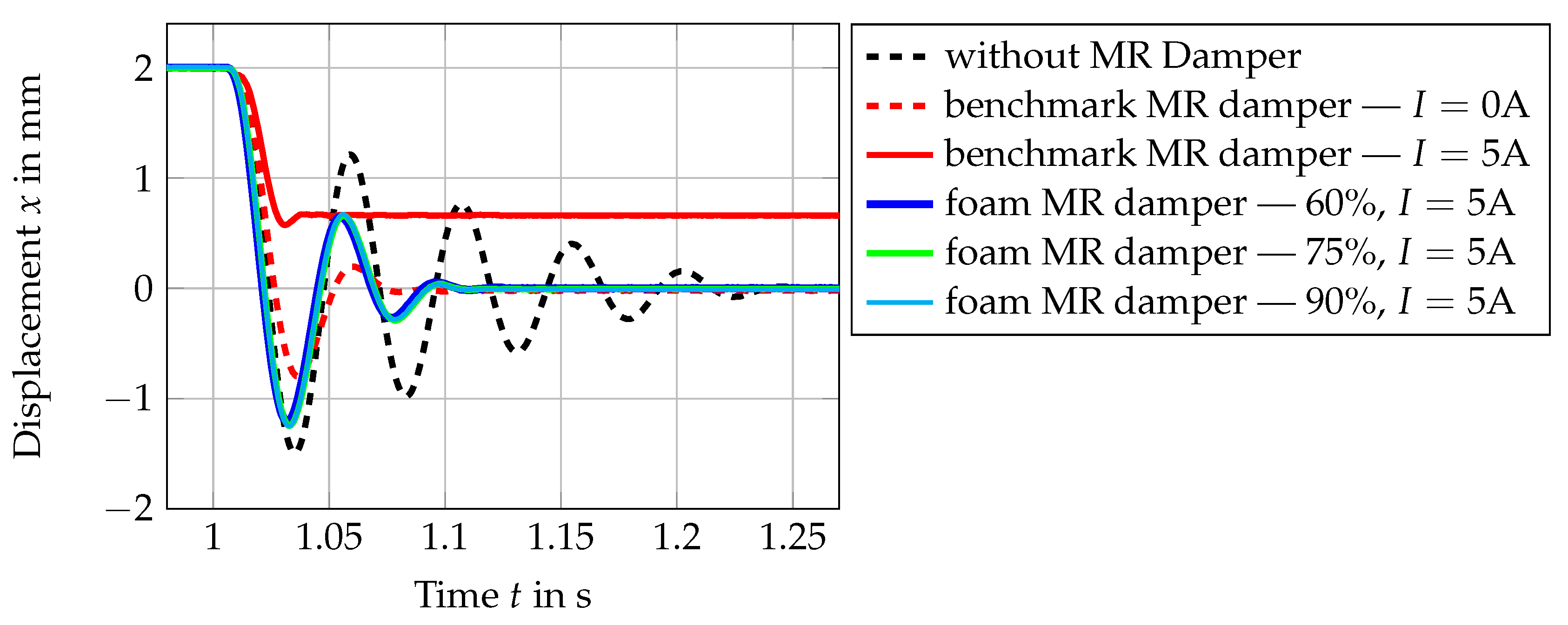
The results in Figure 18 show the results when both the benchmark damper and the foam damper are activated with an applied current of 5 A.
As can be seen in this figure, for the ON state of the foam MR damper with 5 A, the damping in the system is increased and therefore, the settling time of the free vibration is reduced from 260 ms to 110 ms. The settling time of the mass with the foam MR damper with 5 A applied current is almost the same settling time achieved by inserting the benchmark MR damper in the vibratory system without activating it. For the case when 5 A is applied for the benchmark MR damper, the settling time is further reduced to 40 ms. It is also to be observed for this case that since the yield force of the benchmark MR damper with 5A is high, the vibrating mass has another settling position.

4.3.2. Equivalent Damping Ratio

The results in Figure 17 and Figure 18 verify the influence of the parasitic damping force in a vibratory system. By having a high parasitic damping in the system, a significant amount of damping is added with it to the system. This results in a reduction of the system dynamic. In order to quantify the damping in the vibratory system, the method in Section 2.5.3 is used. This method allow an estimation of the damping ratio D of the system based on the peak of the amplitude response of the vibratory system. In this way, an equivalent damping ratio can be obtained despite the system being nonlinear.
In order to obtain the equivalent damping ratio, a simulation using the identified parameters of both dampers and the vibratory system is conducted. The damper identifications in Section 4.1 and Section 4.2 give the value of the friction force F R due to the sealing or guide of the damper, viscous damping constant, d ( I ) and the blocking force F 0 ( I ) for different applied current conditions. The obtained parameters can be found in the Table 2. The other two parameters, namely, the friction constant F G from the guides of the moving mass and the damping constant d air from air were identified in Section 4.3 and listed in Table A4. The simulation is conducted using SIMULINK 10.0 from MATLAB2019b. All the known parameters are inserted in the simulation and a chirp signal
F a ( t ) = k sin 2 π c 2 t 2
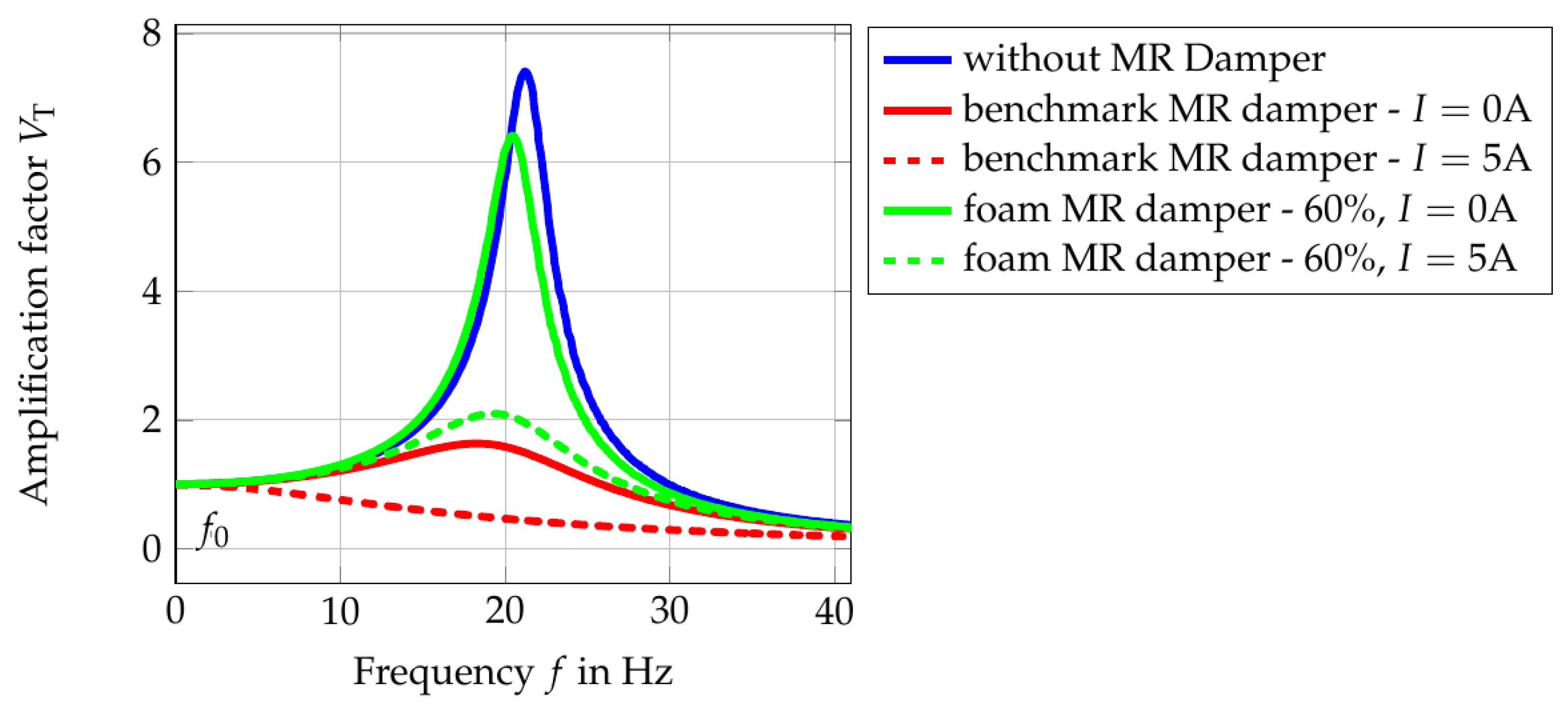
is used as the input, with k as the vibratory system stiffness and c = 0.42 as the rate of change of the frequency over time. c is chosen so that the chirp rate is slow enough to build the figure. Figure 19 shows the amplitude response of the vibratory system for different damper conditions.
In this figure, the peaks of the system response are enveloped and plotted over the frequency. The investigation is conducted up to the frequency twice the natural frequency of the vibratory system. The maximum point of each amplitude response is taken as the quality factor Q. By inserting the peak value Q in Equation (24), the damping ratio D can be estimated. The calculated equivalent damping ratio is listed in Table 3.
The results show that the utilization of the benchmark MR damper in the vibratory system increased the default damping ratio D from 0.067 to 0.323 just by attaching it to the vibratory system. By increasing the applied current to the maximal amount of 5 A, the vibratory system possesses an equivalent damping ratio that might be bigger than 0.707 (see Section 2.5.3). That means that by using the benchmark MR damper, the damping of the system can be operated with a damping ratio range from 0.323 to a damping ratio that could be bigger than 0.707. In small-scale applications, the damping ratio of 0.323 is considered to be big. As can be seen in Figure 17, the system response becomes slower just by attaching it to the system. In comparison to that, the utilization of the foam MR damper changed the default damping ratio D from 0.067 to 0.078. It can be said that the dynamic of the system is almost unchanged. However, due to less interaction between activated MR particles and the shear surface, the generated damping force is also less in comparison to the benchmark MR damper. With an applied current of 5 A, the equivalent damping ratio of the system becomes 0.246, which is still smaller than the damping ratio of the benchmark MR damper in its OFF state. Nevertheless, as explained in the design procedure, the upper limit of the proposed MR damper can be increased easily without changing the dynamic of the system.
5. Conclusions

In this work, a foam MR damper design concept to be used in small applications is proposed. The proposed MR damper design addresses the two issues that hold the MR damper to be applied in small-scale applications, namely, the parasitic damping force and the additional mass. The parasitic damping force is minimized by using the nickel foam in the fluid chamber, eliminating the contact with the shearing plate in its OFF state. The additional mass due to the electromagnet is solved by building the electromagnet on the outer side of the moving part. This results in an MR damper with low parasitic damping force in its OFF state and low moving mass, which make the concept suitable to be implemented in the small-scale application. A prototype of the proposed foam MR damper was built and its characteristic was investigated. In verifying its performance, a benchmark MR damper is built. The benchmark MR damper is constructed to have comparable operating conditions. This benchmark MR damper represents the MR dampers in general, where parasitic damping has a significant influence on the dynamic of the vibratory system. The characteristic of the benchmark MR damper was also investigated using the same investigation procedure. From the investigation of the MR dampers characteristic, it was shown that the parasitic damping can be minimized using the proposed foam MR damper. The proposed foam MR damper possesses a passive friction force that is 8× smaller and OFF state passive viscous damping that is 10–20× smaller than the benchmark MR damper.
Together with the benchmark MR damper, the performances of the proposed MR damper are investigated using the same procedure in a constructed test rig. The damping is then quantified using the quality factor Q, where an equivalent damping ratio D can be calculated. From the performance comparison, it is shown that the utilization of the proposed MR damper with a low parasitic damping does not change the vibratory system dynamic during its OFF state. To the contrary, the installation of the benchmark MR damper in the vibratory system alone adds a significant amount of damping to the system. Despite being operated in the OFF state, the parasitic damping from the benchmark MR damper changes the vibratory system dynamic. It is to be noted, that the electromagnet benchmark MR damper in this work was not integrated at the moving part, which could lead to a further reduction in the system dynamics. The comparisons show the importance of minimizing the parasitic damping. The only drawback of the proposed foam MR damper is its low dynamic operating range.
It can be concluded from the investigation and experimental results, that the design configuration of the proposed MR damper results in a low parasitic damping force and a low moving mass of the damper. This results in a preservation of the vibratory system dynamics. Based on the results, the proposed MR damper is suitable to be implemented in small-scale applications. An example for such application is a prototype or miniature of a large-scale system. For future works, experimental uncertainty studies should be performed. Moreover, a mathematical model to describe the characteristic of the proposed MR damper configuration should be investigated. Additionally, it is also an interesting aspect to study the magneto-thermal importance, as in [28,29], for the proposed MR damper configuration, above all in the first design phase via software. This is because of the properties and the dynamics of the electromagnet; therefore, the MR damper can depend on the thermal influence of the environment or the system itself.

Author Contributions

A.S.T. contributed to the conceptualization and methodology of the research. Together with R.S., A.S.T. built the experimental setup and performed the experiments. The investigation, data curation, and writing were performed by A.S.T. The supervision, review and editing were done by T.S. All authors have read and agreed to the published version of the manuscript.

Funding

This research was funded by the German Research Foundation, Deutsche Forschungsgemeinschaft (DFG) within the priority program SPP 1897, “Calm, Smooth, and Smart”.

Data Availability Statement

No new data were created or analyzed in this study. Data sharing is not applicable to this article.

Conflicts of Interest

The authors declare no conflict of interest.

Appendix A. List of Parameters

Table A1. Design parameters of the utilized electromagnet shown in Figure 5a.
Physical PropertyValueUnit
Allowable current density J alw 4A/mm 2
Blocking force F 0 (s.1)10N
Operating area A op (s.2)15 × 10 4 m 2
   - cross-section thickness t m 0.050m
   - cross-section height h m 0.030m
Design yield stress τ 0 (s.3)40kPa
Required flux density B (s.4)0.7T
Required flux Φ (s.4)0.0011Wb
Relative permeabilities(s.5)
   - air μ r , air 1-
   - foam μ r , Ni - foam 12-
   - iron μ r , Fe 2000-
Geometry parameters (s.5)
   - coil housing thickness t hc 2.5mm
   - buffer b buff 5.5mm
Copper density ρ 20 1.7 × 10 8 Ω ·m
Max. op. temperature T max 70 C
Heat transfer coef. α 0.0041/K
Wire diameter d Dr 0.0015m
Max. op. voltage U max 10V
Table A2. Design parameters of the proposed foam MR damper in Section 3.2.
Physical PropertyValueUnit
Metal foam dimension
   - length l f 92mm
   - width b f 31mm
   - thickness t f 3mm
   - volume V f 8.6 × 10 6 mm 3
Plate thickness t p 0.8mm
Plate length l op 18mm
Shear operating dimension
   - length l p 50mm
   - width b p 30mm
   - gap h op {0.5, 1.0, 1.5}mm
Operating area A op 1500mm 2
Table A3. Design parameters of the benchmark MR damper in Section 3.3.
Physical PropertyValueUnit
Shearing plate dimension
   - length l p 25mm
   - width b p 31mm
   - thickness t p 3.2mm
Plate length l op 18mm
Shear operating dimension
   - length l p 25mm
   - width b p 30mm
   - gap h op 1mm
Operating area A op 1500mm 2
Table A4. Parameters of the vibratory system in Section 3.4.
Physical PropertyValueUnit
moving mass m1.7kg
spring stiffness k25kN/m
natural frequency ω 0 133.63rad/s
natural frequency f 0 21.26Hz
default damping d air 25.25Ns/m
default friction F G 0.5N

References

  1. Wang, J.; Meng, G. Magnetorheological fluid devices: Principles, characteristics and applications in mechanical engineering. Proc. Inst. Mech. Eng. Part L J. Mater. Des. Appl. 2001, 215, 165–174. [Google Scholar] [CrossRef]
  2. Wereley, N. Magnetorheology: Advances and Applications; Royal Society of Chemistry Publisher: Cambridge, UK, 2014. [Google Scholar] [CrossRef]
  3. Aziz, M.A.; Mohtasim, S.M.; Ahammed, R. State-of-the-art recent developments of large magnetorheological (MR) dampers: A review. Korea-Aust. Rheol. J. 2022, 34, 105–136. [Google Scholar] [CrossRef]
  4. Oh, J.S.; Choi, S.B. Ride Quality Control of a Full Vehicle Suspension System Featuring Magnetorheological Dampers With Multiple Orifice Holes. Front. Mater. 2019, 6, 8. [Google Scholar] [CrossRef] [Green Version]
  5. Narwade, P.; Deshmukh, R.; Nagarkar, M.; Sukhwani, V. Improvement of Ride Comfort in a Passenger Car Using Magneto Rheological (MR) Damper. J. Vib. Eng. Technol. 2022, 10, 2669–2676. [Google Scholar] [CrossRef]
  6. Dyke, S.; Spencer, B.; Sain, M.; Carlson, J. Seismic Response Reduction Using Magnetorheological Dampers. In Proceedings of the 13th World Congress of IFAC, San Francisco, CA, USA, 30 June–5 July 1996; Volume 29, pp. 5530–5535. [Google Scholar] [CrossRef]
  7. Weber, F.; Distl, H. Amplitude and frequency independent cable damping of Sutong bridge and Russky bridge by magnetorheological dampers. Struct. Control. Health Monit. 2015, 22, 237–254. [Google Scholar] [CrossRef]
  8. Tu, J.; Li, Z.; Zhang, J.; Gao, K.; Liao, J.; Gao, J. Development, test, and mechanical model of the leak-proof magnetorheological damper. Front. Mater. 2019, 6, 118. [Google Scholar] [CrossRef] [Green Version]
  9. Desai, R.M.; Jamadar, M.E.H.; Kumar, H.; Joladarashi, S.; Rajasekaran, S.C.; Amarnath, G. Evaluation of a commercial MR damper for application in semi-active suspension. SN Appl. Sci. 2019, 1, 993. [Google Scholar] [CrossRef] [Green Version]
  10. Bui, D.Q.; Hoang, V.L.; Le, H.D.; Nguyen, H.Q. Design and Evaluation of a Shear-Mode MR Damper for Suspension System of Front-Loading Washing Machines. In Proceedings of the International Conference on Advances in Computational Mechanics, Phu Quoc, Vietnam, 2–4 August 2017; Nguyen-Xuan, H., Phung-Van, P., Rabczuk, T., Eds.; Springer: Singapore, 2018; pp. 1061–1072. [Google Scholar]
  11. Jolly, M.R.; Bender, J.W.; Carlson, J.D. Properties and Applications of Commercial Magnetorheological Fluids. J. Intell. Mater. Syst. Struct. 1999, 10, 5–13. [Google Scholar] [CrossRef]
  12. Greiner-Petter, C.; Tan, A.S.; Sattel, T. A semi-active magnetorheological fluid mechanism with variable stiffness and damping. Smart Mater. Struct. 2014, 23, 115008. [Google Scholar] [CrossRef]
  13. Macháček, O.; Kubík, M.; Strecker, Z.; Roupec, J.; Mazůrek, I. Design of a frictionless magnetorheological damper with a high dynamic force range. Adv. Mech. Eng. 2019, 11, 1–8. [Google Scholar] [CrossRef] [Green Version]
  14. Carlson, J. David and Jolly, Mark R. MR fluid, foam and elastomer devices. mechatronics 2000, 10, 555–569. [Google Scholar] [CrossRef]
  15. Chrzan, M.J.; Carlson, J.D. MR fluid sponge devices and their use in vibration control of washing machines. In Proceedings of the Smart Structures and Materials 2001: Damping and Isolation, Newport Beach, CA, USA, 5–7 March 2001; Inman, D.J., Ed.; International Society for Optics and Photonics, SPIE: Bellingham, WA, USA, 2001; Volume 4331, pp. 370–378. [Google Scholar] [CrossRef]
  16. Liu, X. Shear performance of novel disk-type porous foam metal magnetorheological (MR) fluid actuator. Optoelectron. Adv. Mater.—Rapid Commun. 2010, 4, 1346–1349. [Google Scholar]
  17. Yan, Y.X.; Hui, L.X.; M, Y.; J, F.; Dong, L.H. Dynamic response time of a metal foam magneto-rheological damper. Smart Mater. Struct. 2013, 22, 025026. [Google Scholar] [CrossRef]
  18. Liu, X.; Gao, X.; Li, F.; Yu, H.; Ye, D. Shear Performance of a Metal Foam Magnetorheological Fluid Damper. IEEE Trans. Magn. 2015, 51, 2343938. [Google Scholar] [CrossRef]
  19. Zhao, D.; Zhao, J.; Zhao, Z.; Liu, Y.; Liu, S.; Wang, S. Design and experimental study of the porous foam metal magnetorheological fluid damper based on built-in multi-pole magnetic core. J. Intell. Mater. Syst. Struct. 2020, 31, 687–703. [Google Scholar] [CrossRef]
  20. Winter, B.D.; Swartz, R.A. Low-force magneto-rheological damper design for small-scale structural control. Struct. Control. Health Monit. 2017, 24, e1990. [Google Scholar] [CrossRef]
  21. Huang, L.; Lia, J.; Zhua, W. Mathematical model of a novel small magnetorheological damper by using outer magnetic field. AIP Adv. 2017, 7, 4978866. [Google Scholar] [CrossRef] [Green Version]
  22. Arus MR Tech Pvt Ltd, 3/27, M.H Road, Chennai—600 011, India. AMT-SMARTEC. 2021. Available online: https://arusmrtech.com/wp-content/uploads/2021/11/SMARTEC.pdf (accessed on 21 November 2022).
  23. Elsaady, W.; Oyadiji, S.O.; Nasser, A. A review on multi-physics numerical modelling in different applications of magnetorheological fluids. J. Intell. Mater. Syst. Struct. 2020, 31, 1855–1897. [Google Scholar] [CrossRef]
  24. Janocha, H. Adaptronics and Smart Structures; Springer: Berlin/Heidelberg, Germany, 2007. [Google Scholar] [CrossRef]
  25. Janocha, H. Unkonventionelle Aktoren; Oldenbourg: Munich, Germany, 2010. [Google Scholar]
  26. Kallenbach, E.; Eick, R.; Ströhla, T.; Feindt, K.; Kallenbach, M.; Radler, O. Elektromagnete—Grundlagen, Berechnung, Entwurf und Anwendung, 5th ed.; Springer: Wiesbaden, Germany, 2017. [Google Scholar] [CrossRef]
  27. Meirovitch, L. Elements of Vibration Analysis, 2nd ed.; McGraw-Hill: New York, NY, USA, 1986. [Google Scholar]
  28. Versaci, M.; Cutrupi, A.; Palumbo, A. A Magneto-Thermo-Static Study of a Magneto-Rheological Fluid Damper: A Finite Element Analysis. IEEE Trans. Magn. 2021, 57, 3032892. [Google Scholar] [CrossRef]
  29. Nieves, P.; Serantes, D.; Chubykalo-Fesenko, O. Self-consistent description of spin-phonon dynamics in ferromagnets. Phys. Rev. B 2016, 94, 014409. [Google Scholar] [CrossRef]
Figure 1. Sketches of known MR damper configurations with foam, where (a) the foam is attaced to the moving piston, (b) the foam is attached to the damper housing wall over the circumference, and (c) the foam is only attached to the lower part of the housing.
Fluids 08 00203 g001
Figure 2. Shear stress τ -shear rate γ ˙ characteristic line of a magnetorheological fluid.
Fluids 08 00203 g002
Figure 3. (a) Sketch of the MR fluid working principle where the shearing exists along the x-axis and (b) the generated force F d -velocity x ˙ characteristic line of a MR fluid operated in shear mode.
Fluids 08 00203 g003
Figure 4. The sketch of the working principle of (a) the proposed MR damper with porous medium and (b) the in-this-work benchmark MR damper, with green block representing the moving plate and red arrows representing the magnetic field direction.
Fluids 08 00203 g004
Figure 5. (a) Sketch of a magnetic circuit of a simple electromagnet and (b) its equivalent circuit of the magnetic circuit, with gray representing the iron block, yellow representing the coil housing and orange representing the coil.
Fluids 08 00203 g005
Figure 6. Configuration of a 1-DOF vibratory system with (a) conventional viscous damper and (b) MR damper.
Fluids 08 00203 g006
Figure 7. Logarithmic plot of the relation between the damping constant d and the mass-stiffness k m from Equation (16) for various damping ratio D.
Fluids 08 00203 g007
Figure 8. The design and construction of the proposed foam MR-damper, where (a) shows the CAD of the whole damper construction, (b) the cut-section in x z -plane at the middle of the shearing plate, and (c) the cut section in y z -plane at the middle of the shearing plate to show the details of the damper construction.
Fluids 08 00203 g008
Figure 9. The design and construction of the benchmark MR-damper, where (a) shows the CAD of the whole damper construction, (b) the cut-section in x z -plane at the middle of the connecting rod, and (c) the cut section in y z -plane at the middle of the shearing plate to show the details of the damper construction.
Fluids 08 00203 g009
Figure 10. Photos of the complete experimental setup with (a) configuration used to investigate the characteristic of the MR dampers and (b) configuration used to investigate the performance of the MR dampers in a vibratory system.
Fluids 08 00203 g010
Figure 11. Comparison between experimental results (marks), theoretical damping force from Equation (36) with calculated parameters (dashed lines), and the theoretical damping force from Equation (37) with fitted parameters (continuous solid lines).
Fluids 08 00203 g011
Figure 12. Photo of the 3D-printed duplicated parts for different operating gap h op of the proposed foam MR damper.
Fluids 08 00203 g012
Figure 13. Measurement results for the investigation of the damping force-velocity characteristic of the proposed foam MR damper, with various MR filling ratio V FR and operating gap distance h op , including its comparison with the mathematical model in Equation (37).
Fluids 08 00203 g013
Figure 14. Photos of the foam MR damper with 1.5 mm gap in its ON-state, showing the drawn-out MR particles creating a contact with the surface of the shearing plate.
Fluids 08 00203 g014
Figure 15. Principle sketch of the vibratory system configuration used in this work.
Fluids 08 00203 g015
Figure 16. Comparison of the free vibrations behavior of the vibratory system without MR damper to investigate the friction constant F G and the damping constant d air .
Fluids 08 00203 g016
Figure 17. Comparison of the free vibrations behavior of the vibratory system, to investigate the influence of the parasitic damping from both MR dampers.
Fluids 08 00203 g017
Figure 18. Comparison of the free vibrations behavior of the vibratory system, to investigate the increment of the damping from both MR dampers at its maximum applied current I = 5 A.
Fluids 08 00203 g018
Figure 19. Comparison between the frequency response of the vibratory system for different MR damper type and applied current.
Fluids 08 00203 g019
Table 1. Physical properties of the MR fluid AMT-SMARTEC + .
Physical PropertyValueUnit
Dynamic viscosity η 0.37Pa·s
Relative permeability μ r 12-
Density ρ 2.9kg/L
Operating temperature T 20 to 150 C
Yield stress τ 0 at B = 1.38 T69kPa
Table 2. List of parameters used to model the shear operating mode of both the benchmark and the proposed foam MR damper.
Damper ParameterI = 0 AI = 1 AI = 2 AI = 3 AI = 4 AI = 5 A
Damping constant in Ns/m
d—benchmark (math. model)0.56
d—benchmark (fitted)100200250300350400
d—60%, h op = 0.5 mm52050557070
d—75%, h op = 0.5 mm52050557075
d—90%, h op = 0.5 mm102050608085
d—90%, h op = 1.0 mm101025303030
Blocking force in N
F τ —benchmark (math. model)05.7812.619.2525.3130.6
F τ —benchmark (fitted)0415273746
F τ —60%, h op = 0.5 mm01.152.64.054.655.25
F τ —75%, h op = 0.5 mm01.22.654.054.655.25
F τ —90%, h op = 0.5 mm01.53.24.34.95.5
F τ —90%, h op = 1.0 mm00.51.01.51.82.1
Friction force in N
F R —benchmark (math. model)4
F R —benchmark (fitted)4
F R —60%, h op = 0.5 mm0.15
F R —75%, h op = 0.5 mm0.15
F R —90%, h op = 0.5 mm0.5
F R —90%, h op = 1.0 mm0.3
Measured magnetic flux density in mT
B—benchmark084.3175.2256.2327.3387.6
B—60%, h op = 0.5 mm−4.378.5163.9241.4312.5379.4
B—75%, h op = 0.5 mm−3.581.5170.2248.7321.0388.3
B—90%, h op = 0.5 mm−3.582.0172.9253.1326.9395.4
Table 3. Equivalent damping ratio of the vibratory system, for the cases where no MR damper, benchmark MR damper and proposed foam MR damper is integrated.
No MRDBenchmark MRDFoam MRD
0 A5 A0 A5 A
D0.0670.323≥0.7070.0780.246
Disclaimer/Publisher’s Note: The statements, opinions and data contained in all publications are solely those of the individual author(s) and contributor(s) and not of MDPI and/or the editor(s). MDPI and/or the editor(s) disclaim responsibility for any injury to people or property resulting from any ideas, methods, instructions or products referred to in the content.