Abstract
Micro vortex generator (MVG) is a currently facile, robust, and feasible device for supersonic and hypersonic flow control. The purpose of this study is to investigate the impact on SWBLI from the streamwise location of MVG. Large eddy simulation (LES) was conducted on MVG controlled supersonic ramp flow to reveal the sensitivity of MVG streamwise position on shock-wave boundary-layer interaction (SWBLI) control. Numerical cases with minor different distances between MVG and ramp corner are carried out. The results are analyzed in time-averaged and instantaneous view, respectively. The results show that streamwise position has a significant effect on SWBLI in some aspects. With minor changes on the streamwise position, the ring-like vortices generated by MVG were very similar, with only small changes in height and intensity. However, the small changes made on the ring-like vortices produced relatively significant changes to the separation region in front of the ramp. In terms of the time-averaged solution, the farther the MVG is from the ramp, the higher the ring-like vortices are lifted, and the shock wave is also disturbed/reduced more strongly. Further, the flow separation zone on the wall also appears smaller. The results of this study play a guiding role for further optimal configuration of MVG in flow control.
1. Introduction
Shock-wave boundary-layer interaction (SWBLI) can influence aircraft and engine performance significantly, leading to undesirable deteriorating flow quality from the production of large-scale flow separation creating unstable and distorted flow, drag rise, engine upstart, total loss of pressure, and high wall heating. SWBLI still presents a formidable problem for researchers today. To reduce the adverse effects caused by SWBLI, the use of micro vortex generators (MVGs) has become widely accepted in the separation control [1]. MVG is a low-profile passive control device, which touts a smaller size (about 10–60%) of the boundary layer thickness in contrast to larger and clunkier conventional vortex generators. The use of MVG gives clear advantages in terms of low profile drag and lack of intrusiveness and robustness, due to its miniature size and passive nature [1].
To increase the performance of the aircraft flap, a high-lift device, MVGs were first proposed in the 1980s. It has thrived in use in subsonic regimes to improve the aerodynamic performance of aircrafts [1] and it has been recently used in supersonic flow to assist in solving the problems caused by SWBLI, especially flow separation [2]. In recent years, an array of experimental investigations with MVG have been carried out. Anderson et al. [3] gave the academic and standardized studies about MVG, and Babinsky et al. [4] made a series of experiments on different MVG designs and performed a detailed study on their control effects. A PIV investigation of the 3D instantaneous flow organization behind a micro-ramp in a supersonic boundary layer was given by Sun et al. [5]. Syalin et al. [6] studied the effect of MVG in improving aerodynamics performance on a WIG wing. Numerous numerical simulations have been done with supersonic ramp flow with or without MVG for comparative studies and further design purposes, using RANS, hybrid RANS/LES, and monotone integrated LES. Using a high-order method, Rizzetta and Visbal [7] simulated the flow field on a compression corner by implicit LES and Kaenal et al. [8] conducted LES on ramp flow using an approximate de-convolution model. Ghosh et al. [9] conducted numerical simulations using RANS and Hybrid LES/RANs under the conditions of Babinsky’s experiment [4]. Similar fundamental flow structures, such as the streamwise vortices and momentum deficit, were reproduced. Lee et al. [10] investigated the SWBLI with various MVG to optimize the control effect. Zhang et al. [11] investigated the induced velocity and the trajectory of the vortices generated by MVGs by using the point vortex model and the effect of the asymmetric micro-ramp was numerically studied at a free stream Mach number of 2.5 via RANS simulations.
In our previous work [12,13], LES of MVG controlled supersonic ramp flow with fully developed turbulent boundary layer was conducted at and to understand the flow characteristics, especially the complicated vortex structures, and the flow separation induced by SWBLI. From the numerical results, a dynamic vortex model was provided [13]. The results of our LES also revealed a series of ring-like (or Ω shaped) vortices behind MVGs that traveled downstream. Furthermore, the shock waves at the ramp corner are weakened substantially when they interact with the boundary layer that contains ring-like vortices at the upper bound. In Ref [14], we further studied the special vortex structures generated by MVG on the flow control in supersonic flows with different Mach numbers.
The role of MVG in flow control, especially in reducing the separation zone caused by ramp shockwave, has been confirmed and studied based on experiments and numerical simulations. There are, however, only a few studies on the optimization of MVG. Optimization problems such as how do we effectively configure MVG for a better flow control, and what are the MVG impacts on the flow field under different configurations, have not been studied in detail.
In the specific engineering application of MVG, the impact of its downstream installation position on the flow field structure and SWBLI is a particularly critical issue. In this study, to investigate the impact on SWBLI from the streamwise location of MVG, four LES simulations of MVG controlled supersonic turbulent boundary layer flows were carried out. The streamwise location of MVG in a ramp flow domain is slightly tuned to reveal the impact of the sensitivity of MVG position on SWBLI control. The paper is organized as follows. In Section 2 we presented the setup of numerical cases and the validation for code; in Section 3 we presented the numerical results in time-averaged view and instantaneous view respectively; and in Section 4 we have given the conclusion.
2. Numerical Methods
In this study, we have solved the Navier–Stokes equations to simulate the fluid flow. From the conservation laws of mass, momentum, and energy, the Navier–Stokes equations are derived as follows:
with
where represents the density of the fluid, the velocity vector, the total energy, the internal shear stress, the internal energy per unit mass, the pressure, the temperature, the thermal conductivity, and the dynamic viscosity.
The equation of state for a thermally perfect gas and the equation for the internal energy are used to close the system,
where is a gas constant and is a specific heat capacity.
A high-order and high-resolution DNS/LES is applied in this study. With expressing the semi-discretized form of a one-dimensional hyperbolic equation as follows,
for the positive flux, the four upwind-biased schemes on four stencils can be given as
The third order is obtained for each individual scheme, combining the schemes in Equation (7), which linearly gives a 5th order central scheme with the coefficients and .
To make the scheme robust for discontinuity solutions, the linear coefficients can be replaced with the corresponding nonlinear ones,
is a small quantity () to prevent the denominator from being zero, which should be small enough in supersonic problems with shocks. are the smoothness functions for the stencils.
For the bandwidth-optimized WENO scheme, a further improvement for by Martin et al. [15] is
where stands for the total variation on each candidate stencil.
3. Case Setup
The dimensions of MVG and half computational domain is displayed in Figure 1. The back edge of MVG is declined to angle to alleviate the difficulty of grid generation, while the other dimensions are given as the same as experiments of Babinsky et al. [4], with and , where represents the height of MVG and represents the distance between the center lines of two adjacent MVG. The geometries of half computational domain are shown in Figure 1b. According to experiments conducted by Babinsky et al. [4], the ratio of the models range from 0.3 to 1 and the proper distance between back edge and control region is around , where represents the incompressible boundary layer nominal thickness. In this study, the height of MVG is supposed to be and the horizontal distance between apex of MVG and ramp corner is set to be , and in four cases. The distance from the ramp corner to the end of ramp is and from the inlet of the domain to front edge of MVG is . The height of the domain changes from to and the width of half domain is . Only half of the grids need to be generated because of the symmetry of the grid distribution. The grid dimensions of whole system are .
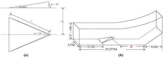
Figure 1.
The dimensions of (a) MVG and (b) the half domain.
The wall boundary applied non-slipping, zero-gradient for pressure and adiabatic boundary conditions. The upper boundary adopted non-reflecting boundary condition to prevent possible wave reflections. The conditions at the front and rear boundary surfaces in the spanwise direction are set as periodic, since the simulation is for the flow around MVG arrays and only one MVG is simulated. At the outflow boundary, a characteristic-based condition which can handle the outgoing flow without reflection is set. Twenty thousand turbulent profiles were used to generate inflow conditions obtained from DNS results [16]. We used these turbulent profiles as the input for the inlet condition to generate fully developed turbulent inflow in front of the MVG. The shape factor of the boundary layer in front of the MVG is , which verifies that the flow before the MVG is fully developed turbulent flow.
The 5th order bandwidth-optimized WENO scheme [17] is utilized to keep the highly fidelity, and monotone integrated LES (MILES) code was adopted by solving the Navier–Stokes. The numerical dissipation is used as a sub-grid stress model [18,19]. The explicit third-order TVD-type Runge–Kutta scheme is employed in time marching.
Four cases have been carried out to investigate the flow separations induced by the shock wave boundary layer interaction of supersonic ramp flow. The flow and reference parameters, including Mach numbers, Reynolds number, etc., are listed in Table 1.

Table 1.
Parameters for the LES cases.
Our in-house LES code was validated through a series of benchmark cases and the MVG controlled supersonic ramp flow at Ma 2.5. The details of the validations and comparison to experimental, numerical, and theoretical results can be found in Ref [13]. Here, we only give a brief description.
Figure 2 gives a quantitative comparison of the case Ma = 2.5 with experiment by Babinsky et al. [4] in the time-averaged velocity profile at and . The same pattern is obtained. The difference between LES and the experiment results is considered to be induced by the different Reynolds numbers and back edge degrees of MVG. Figure 3 shows the two streamwise vortices in time-averaged view. A novel vortex identification method, Rortex/Liutex [20], is utilized. Rortex/Liutex uses RS decomposition to separate non-dissipative rigid rotation from dissipative shear as shown,
where is the real eigenvector of and .
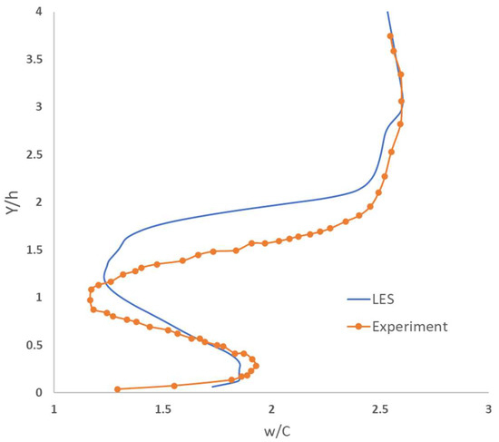
Figure 2.
Time-averaged velocity profiles at .
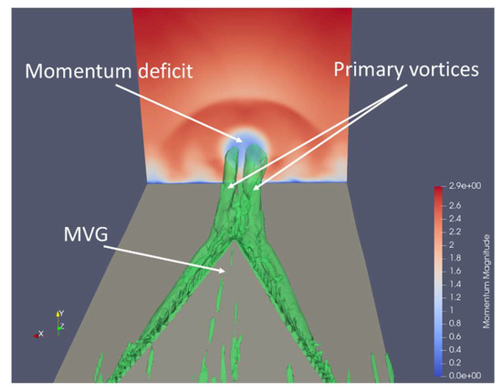
Figure 3.
Two streamwise vortices in time-averaged view.
The green surfaces are the Liutex iso-surface of which represent the structures of vortices, and the colorful plane shows the momentum distribution. The structure of primary vortices and the momentum deficit are conspicuous in the downstream of MVG.
4. Numerical Results and Discussion
4.1. Revisit the Mechanism How MVG Reduce the Flow Separation
In this section, we will revisit the mechanism of how MVG reduces the flow separation induced by shock waves. As revealed in a previous paper [12,13,14], a momentum deficit zone is generated behind the MVG and a sequence of ring-like vortex is formed, see Figure 4. These vortex rings travel down and interact with shock waves (Figure 5). As a result of the low-pressure region inside the vortex rings, the pressure after the shock waves is reduced and the shock waves are weakened and altered. Thereafter, the adverse pressure gradient in boundary layer is undermined and the flow separations induced by the shock waves are reduced. Figure 6 shows the time-averaged results of flow separation reduction by displaying the distribution of on the wall, where is streamwise velocity and is the direction norm to the wall. The blue region surrounded by thick black lines are separation regions. From the time-averaged results, we can find that the separation is reduced significantly in the central region because of the vortex rings. Since there are few influences from the vortex rings on the flow at the sides, the separation region keeps the original size.
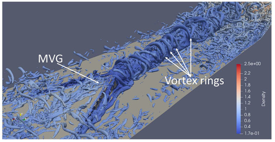
Figure 4.
A sequence of vortex rings is generated behind MVG.
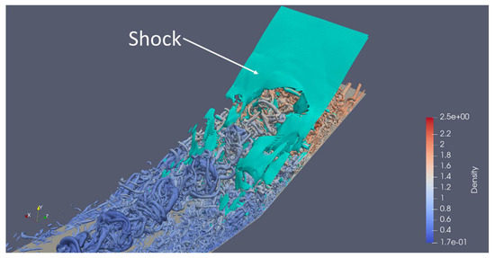
Figure 5.
Vortex rings interact with shock waves.
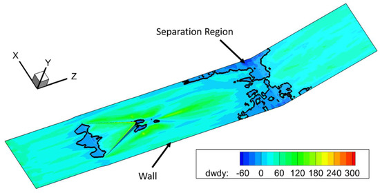
Figure 6.
In time-average view, the reduced flow separation due to the vortex rings is generated by MVG.
4.2. Impact of the Minor Changes of Distance between MVG and Ramp Corner on SWBLI Separation
Figure 7 shows the vortex structures in the four cases of this study. Liutex iso-surface (), contoured by streamwise velocity magnitude, was used to illustrate the vortex structures. It can be found that, with different distances between MVG and ramp corner, the large-scale ring-like vortices in these four cases are quite similar, especially in the size, topology, and frequency.
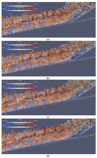
Figure 7.
Vortex structure illustrated by Liutex iso-surface with , (a) case 1, (b) case 2, (c) case 3, (d) case 4.
In order to better compare the flow structures in the four cases, the time-averaged solution based on 50,000-time steps (, where is characteristic time in Table 1.) was obtained. Figure 8 shows the time-averaged Liutex distribution on a cross section at the ramp corner. The blue color means no vortices, while the green indicates the location of vortex. If the ramp corner is further away from MVG, ring-like vortices have a relatively longer distance to develop and be lifted up. This can also be observed in Figure 8. However, in this study, the distance between the MVG and the ramp corner in the four cases is not much different (the maximum difference is 1.5 h), so the approximate height of the ring-like vortices arriving at the ramp corner is not much different—between 1.5 h and 4 h.
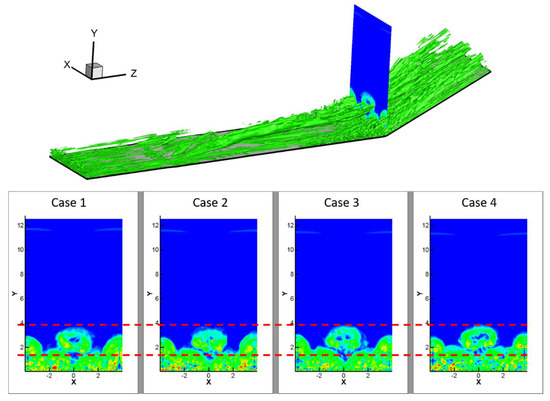
Figure 8.
The position of ring-like vortex at the ramp corner.
Figure 9 shows the spanwise vorticity component () distribution on the central streamwise section of the domain () in time-average view. In these figures, the upper red strip region is mainly from the trace of the clockwise ring-like vortices’ top part. It can be found that the heights of the upper red traces are basically the same in these four cases, but the intensity of vorticity in the latter cases gradually weakens. As ring-like vortices develop more in later cases, their intensity is correspondingly reduced. However, the relative width increases accordingly. In addition, the red regions at the ramp corner in Figure 9 correspond to the separation zones. It can be found that the separation zone in the latter cases is also gradually reduced.
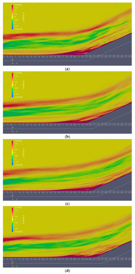
Figure 9.
In time-average view, the vorticity distribution on the streamwise central plane, (a) case 1, (b) case 2, (c) case 3, (d) case 4.
In order to have a better quantitative comparison of the vortex intensity and distribution in the four cases, the spanwise vorticity component distributions along the wall normal direction (Y) at upstream of the ramp corner ( and respectively) on the streamwise central section are given in Figure 10. It can be seen that the rough profiles of the vorticity distributions are basically similar. The vorticity maxima are reduced in latter cases, but the difference is not significant, except that the position is shifted.
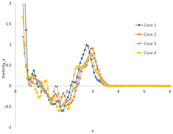
Figure 10.
Distribution of the spanwise component of vorticity along the wall-normal direction.
As a conclusion, small changes in the spacing of the MVG and ramp corners have little effect on the main vortex structure, especially the ring-like vortices. In the case of slightly larger spacing, ring-like vortices have a relatively high position due to longer distance development, but their strength is relatively weakened. However, from the distribution of pressure gradient values given in Figure 11, the ramp shocks are quite different in these four cases. The lower part of the ramp shock shows a weaker lambda bifurcation in Figure 11a, but in subsequent cases this bifurcation moves more and more upwards. Especially in case 3 and case 4, the ramp shock is severely weakened at the thickness of the boundary layer and is almost discontinuous. The change of the ramp shock wave reflects the effect of the vortex structure behind the MVG, especially the ring-like vortices, on the shock wave. Smaller changes in ring-like vortices bring relatively large effects on shock waves.
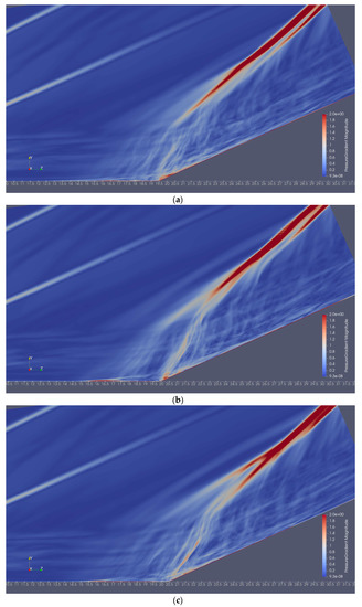
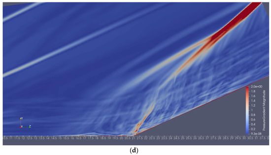
Figure 11.
In time-average view, the distribution of pressure gradient magnitude on the streamwise central plane, (a) case 1, (b) case 2, (c) case 3, (d) case 4.
To further investigate the impact on separation zone, Figure 12 shows the distribution of (derivative of the streamwise velocity along the wall normal direction) on the wall. The black lines are the contour lines of , which indicate the flow separation boundary. The red vertical line indicates the position of ramp corner. From this figure, we can see that the distance between MVG and ramp corner has an impact on the separation regions. With increase of the distance (from to ), the separation region reduction becomes wider (from a “V” shape to a “U” shape). The reduced part of the separation zone is concentrated in the middle of the flow field, that is, where the ring-like vortices are concentrated. This also confirms the important role of ring-like vortices in SWBLI. As the distance between the MVG and the ramp corner lengthens, although there are only minor changes in ring-like vortices, these changes have a relatively large impact on the flow separation region. The separation zone is reduced to a relatively greater extent by ring-like vortices with higher position and larger size. In order to have a quantitative comparison, a area in the central of the upstream wall surface of the ramp corner was chosen (see the small red rectangle in Figure 12). The area integrals of in this area in the four cases are 6.05, 54.26, 176.23, and 189.51. A larger value represents a greater weakening of the separation zone and a greater improvement in the velocity profile.
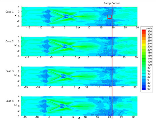
Figure 12.
The flow separation in time-averaged view of four cases.
In the instantaneous view, Figure 13 shows the signals of streamwise velocity near the wall of ramp corner center with . The black spot in the upper figure shows the location where the signal is probing. The four figures at the bottom shows the streamwise velocity probed from the black spot in four cases. The period we probe the data is , where is characteristic time in Table 1.
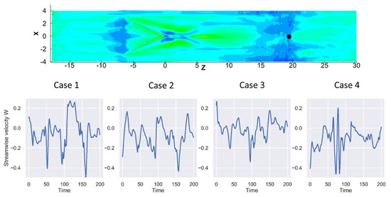
Figure 13.
The signals of streamwise velocity at the wall of ramp corner center (position indicated by the black spot in the upper figure).
These signals indicate the oscillation of flow separation region. We use these signals to implement spectrum analyses to find the impact of the distance between MVG and ramp corner on separation region oscillation. Figure 14 shows the spectrum analysis on the signals in Figure 13. The y-axis is spectrum magnitude and the x-axis is Strouhal number, which is the dimensionless frequency defined as
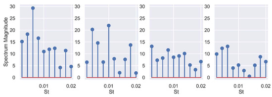
Figure 14.
The spectrum analysis on the signals in Figure 13.
From Figure 14, we find that the dominant frequency and magnitude is 0.006 and 29 in case 1, 0.01 and 22 in case 2, 0.002 and 14 in case 3, and 0.006 and 14 in case 4. We can figure out that the spectrum magnitude of dominant frequency reduces significantly as the distance increases. However, it has little effect on the dominant frequency, as there is no manifest pattern for dominant frequency with respect to the distance.
5. Conclusions
In this study, the impact on SWBLI from the streamwise location of MVG is investigated. LES was performed to reveal the sensitivity of MVG streamwise location to SWBLI control. Numerical cases with small changes in the distance between the MVG and the corner of the ramp were studied. The results show that small changes in MVG and ramp corner spacing have little effect on the main vortex structure, especially the ring-like vortex structure. In the case of a slightly larger spacing, the position of the ring-like vortices is relatively high, and the size is relatively large when they travel to the ramp corner. However, small differences in spacing have relatively large effects on ramp shock waves. With larger spacing, ramp shock waves are weakened extensively where SWBLI occurs. Therefore, small changes in MVG and ramp corner distance have relatively large effects on the flow separation region. If the distance is longer, the separation zone is reduced to a relatively large extent by the ring-like vortices. Of course, for the optimization of MVG in specific applications, there is still a lot of work to be done. This paper only conducts preliminary work on the sensitivity of the installation location of MVG. In the future, more optimization parameters will be considered.
Author Contributions
Conceptualization and methodology, Y.Y. (Yonghua Yan) and Y.Y. (Yong Yang); formal analysis, Y.Y. (Yonghua Yan), D.L.B., Y.Y. (Yong Yang), C.C. and T.A.K.; writing—original draft preparation, Y.Y. (Yonghua Yan) and Y.Y. (Yong Yang); writing—review and editing, Y.Y. (Yonghua Yan), D.L.B., Y.Y. (Yong Yang), C.C. and T.A.K.; visualization, Y.Y. (Yong Yang), Y.Y. (Yonghua Yan), T.A.K. All authors have read and agreed to the published version of the manuscript.
Funding
This research is funded in part by the National Science Foundation’s Implementation Grants # 1912191 and 1330801, Mississippi NASA EPSCoR and Mississippi INBRE- funded by an Institutional Development Award from the National Institute of General Medical Sciences of the National Institutes of Health under grant number P20GM103476.
Acknowledgments
This work used the Extreme Science and Engineering Discovery Environment (XSEDE), which is supported by National Science Foundation grant number ACI-1548562.
Conflicts of Interest
The authors declare no conflict of interest.
Nomenclature
| MVG | Micro vortex generator |
| SWBLI | Shock wave-boundary layer interaction |
| DNS | Direct numerical simulation |
| LES | Large eddy simulation |
| RANS | Reynolds-averaged Navier–Stokes |
| PIV | Particle Image Velocimetry |
| Density of the fluids | |
| Velocity vector | |
| Total energy | |
| Internal shear stress | |
| Internal energy per unit mass | |
| Pressure | |
| Temperature | |
| Thermal conductivity | |
| Dynamic viscosity | |
| Gas constant | |
| Specific heat capacity | |
| Ma | Mach |
| Reynolds number based on momentum thickness | |
| Micro ramp height | |
| Incompressible boundary layer nominal thickness | |
| Distance between apex of MVG and ramp corner | |
| Characteristics time | |
| Sound speed | |
| Frequency | |
| Strouhal number | |
| Spanwise, normal and streamwise coordinate axes | |
| Spanwise, normal and streamwise velocity | |
| Subscript | |
| w | wall |
| free stream | |
References
- Ashill, P.R.; Fulker, J.L.; Hackett, K.C. A review of recent developments in flow control. Aeronaut. J. 2005, 109, 205–232. [Google Scholar] [CrossRef]
- Lin, J.C. Review of research on low-profile vortex generators to control boundary-layer separation. Prog. Aerosp. Sci. 2002, 38, 389–420. [Google Scholar] [CrossRef]
- Anderson, B.; Tinapple, J.; Surber, L. Optimal Control of Shock Wave Turbulent Boundary Layer Interactions Using Micro-Array Actuation. In Proceedings of the 3rd AIAA Flow Control Conference, American Institute of Aeronautics and Astronautics, San Francisco, CA, USA, 5–8 June 2006. [Google Scholar]
- Babinsky, H.; Li, Y.; Pitt Ford, C.W. Microramp Control of Supersonic Oblique Shock-Wave/Boundary-Layer Interactions. AIAA J. 2009, 47, 668–675. [Google Scholar] [CrossRef]
- Sun, Z.; Scarano, F.; van Oudheusden, B.W.; Schrijer, F.F.J.; Yan, Y.; Liu, C. Numerical and Experimental Investigations of the Supersonic Microramp Wake. AIAA J. 2014, 52, 1518–1527. [Google Scholar] [CrossRef][Green Version]
- Syahin, A.A.T.; Zinnyrah, M.; Azfar, N.A.; Said, I.; Idris, A.C.; Rahman, M.R.A.; Saad, M.R. Effect of micro-ramp vortex generator in improving aerodynamics performance of wing-in-gound craft fuselage. PERINTIS Ejournal 2021, 11, 61–69. [Google Scholar]
- Rizzetta, D.P.; Visbal, M.R. Application of Large-Eddy Simulation to Supersonic Compression Ramps. AIAA J. 2002, 40, 1574–1581. [Google Scholar] [CrossRef]
- Kaenel, R.V.; Kleiser, L.; Adams, N.A.; Vos, J.B. Large-Eddy Simulation of Shock-Turbulence Interaction. AIAA J. 2004, 42, 2516–2528. [Google Scholar] [CrossRef]
- Ghosh, S.; Choi, J.-I.; Edwards, J.R. Numerical Simulations of Effects of Micro Vortex Generators Using Immersed-Boundary Methods. AIAA J. 2010, 48, 92–103. [Google Scholar] [CrossRef]
- Lee, S.; Loth, E. Supersonic Boundary Layer Interactions with Various Micro-Vortex Generator Geometries. Aeronaut. J. 2009, 113, 683–697. [Google Scholar] [CrossRef]
- Zhang, B.; Zhao, Q.; Xiang, X.; Xu, J. An improved micro-vortex generator in supersonic flows. Aerosp. Sci. Technol. 2015, 47, 210–215. [Google Scholar] [CrossRef]
- Yang, Y.; Yan, Y.; Liu, C. ILES for mechanism of ramp-type MVG reducing shock induced flow separation. Sci. China Phys. Mech. Astron. 2016, 59, 124711. [Google Scholar] [CrossRef]
- Yan, Y.; Chen, L.; Li, Q.; Liu, C. Numerical study of micro-ramp vortex generator for supersonic ramp flow control at Mach 2.5. Shock. Waves 2017, 27, 79–96. [Google Scholar] [CrossRef]
- Yan, Y.; Yang, Y.; Chen, C.; Cotton, H.A.; Serrano, A. Numerical study on the ring-like vortex structure generated by MVG in high-speed flows with different Mach numbers. Jpn. J. Indust. Appl. Math. 2022, 39, 3–18. [Google Scholar] [CrossRef]
- Martín, M.P.; Taylor, E.M.; Wu, M.; Weirs, V.G. A bandwidth-optimized WENO scheme for the effective direct numerical simulation of compressible turbulence. J. Comput. Phys. 2006, 220, 270–289. [Google Scholar] [CrossRef]
- Yan, Y.; Tang, J.; Liu, C.; Yang, F. DNS study on the formation of Lambda rotational core and the role of TS wave in boundary layer transition. J. Turbul. 2016, 17, 572–601. [Google Scholar] [CrossRef]
- Jiang, G.-S.; Shu, C.-W. Efficient Implementation of Weighted ENO Schemes. J. Comput. Phys. 1996, 126, 202–228. [Google Scholar] [CrossRef]
- LarKermani, E.; Roohi, E.; Porté-Agel, F. Evaluating the modulated gradient model in large eddy simulation of channel flow with OpenFOAM. J. Turbul. 2018, 19, 600–620. [Google Scholar] [CrossRef]
- Zahiri, A.-P.; Roohi, E. Anisotropic minimum-dissipation (AMD) subgrid-scale model implemented in OpenFOAM: Verification and assessment in single-phase and multi-phase flows. Comput. Fluids 2019, 180, 190–205. [Google Scholar] [CrossRef]
- Liu, C.; Gao, Y.; Tian, S.; Dong, X. Rortex—A new vortex vector definition and vorticity tensor and vector decompositions. Phys. Fluids 2018, 30, 035103. [Google Scholar] [CrossRef]


Publisher’s Note: MDPI stays neutral with regard to jurisdictional claims in published maps and institutional affiliations. |
© 2022 by the authors. Licensee MDPI, Basel, Switzerland. This article is an open access article distributed under the terms and conditions of the Creative Commons Attribution (CC BY) license (https://creativecommons.org/licenses/by/4.0/).