Review

Impact of the Dissipation on the Nonlinear Interactions and Turbulence of Gravity-Capillary Waves

Laboratoire MSC Matière et Systèmes Complexes, Université Paris Cité, CNRS (UMR 7057), 75013 Paris, France
Fluids 2022, 7(4), 137; https://doi.org/10.3390/fluids7040137
Submission received: 1 March 2022 / Revised: 30 March 2022 / Accepted: 6 April 2022 / Published: 12 April 2022
(This article belongs to the Special Issue Nonlinear Wave Hydrodynamics, Volume II)

Abstract

:
Gravity-capillary waves at the water surface are an obvious example illustrating wave propagation in the laboratory, and also nonlinear wave phenomena such as wave interactions or wave turbulence. However, at high-enough frequencies or small scales (i.e., the frequencies typically above 4 Hz or wavelengths below 10 cm), the viscous dissipation cannot be neglected, which complicates experimental, theoretical, and numerical approaches. In this review, we first derive, from the fundamental principles, the features of the gravity-capillary waves. We then discuss the origin and the magnitude of the viscous wave. dissipation in the laboratory and under field conditions. We then show that the significant level of dissipation has important consequences on nonlinear effects involving waves. The nonlinearity level quantified by the wave steepness must be large enough to overcome the viscous dissipation. Specifically, using water as fluid in the field and in the laboratory, nonlinear wave interactions and wave turbulence occur most of the time in a non-weakly nonlinear regime, when the waves are in the capillary or gravity-capillary range.

Graphical Abstract

1. Introduction

The example of the surface waves propagating at the interface between the atmosphere and a water free surface constitutes an example of prime interest for illustrating water waves. The main restoring force is gravity at large scales, and the capillarity for scales smaller than the capillary length, i.e., λ / ( 2 π ) < γ / ( ρ g ) (with λ being the wavelength, ρ the liquid density, and g the gravity acceleration at the Earth’s surface). These waves are commonly observed, such as the waves created by the wind on the sea or the ripples obtained by gently perturbing a water tank. Nevertheless, the surface waves present most of the difficulties, which can occur in the physics of waves; thus spoke Richard Feynman in The Feynman Lectures on Physics Volume I [1]: “Now, the next waves of interest, that are easily seen by everyone and which are usually used as an example of waves in elementary courses, are water waves. As we shall soon see, they are the worst possible example, because they are in no respects like sound and light; they have all the complications that waves can have”.
The water depth influences strongly the structure and velocity of waves. They are modified by the surrounding currents and the hydrodynamic flows [2]. Their propagation is dispersive. Finally, the wave dissipation and the wave non-linearity are often non-negligible. For large liquid depths, the main nonlinear parameter for water waves is given by the wave slope s, which is well approximated by the product of the wave amplitude η by the main wavenumber k, s = η k . For example, at the laboratory scale, ripples of amplitude of one millimeter have a nonlinear parameter of order 0.1 for a wavelength smaller than ten centimeters. The nonlinearity is, thus, unavoidable to describe their propagation. Therefore, three-wave processes for gravity-capillary waves and four-wave processes for gravity waves (as the dispersion relation prevents three-wave interaction for pure gravity waves) have been extensively studied [3,4,5] since their discovery around 1960 [6,7,8], but nearly exclusively for interactions which are said to be resonant, i.e.,:
ω 1 ± ω 2 ± ω 3 = 0 and k 1 ± k 2 ± k 3 = 0
for the three-wave interaction process, and:
o m e g a 1 ± ω 2 ± ω 3 ± ω 4 = 0 and k 1 ± k 2 ± k 3 ± k 4 = 0
for the four-wave interaction process.
One indeed assumes that only wave interactions verifying the resonant conditions contribute to the energy balance of the wave field [3,9,10] after averaging on a sufficient number of periods or wavelengths, although, contrary to the nonlinear optic case [11], the corresponding proof is not clearly presented in the literature. Then, neglecting the dissipation, a triad (or a quartet) verifying the resonance conditions constitutes a nonlinear dynamical system, where the components of the triad exchange energy by nonlinear oscillations [4], with the condition of phase coherence of the wave components during the interaction. For a random set of numerous waves whose phases are uncorrelated, a different framework has been developed to treat the long-term behavior statistically, namely, the wave turbulence theory or the weak turbulence theory [12,13], among other hypotheses of small-scale dissipation and of weak nonlinearity. The experimental application of the wave turbulence concepts to the case of capillary waves constitutes the object of the third part of this document. Previously, we emphasized that, for water waves at the laboratory scale, the dissipation is far from negligible, as a capillary wave is usually damped by viscosity, typically on a distance of ten centimeters. However, most theoretical methods to obtain the interaction coefficients require the absence of dissipation. Despite their importance, few works have investigated the nonlinear interactions of surface waves in the laboratory. Moreover, to our knowledge, to describe their observations, the experimenters added dissipation as a perturbing term to the inviscid theory [14,15] without decomposing the wave velocity field into a potential part and a rotational part. Although the energy carried by gravity-capillary waves is significantly smaller compared to long gravity waves with a wavelength above the meter, the study of short waves is important to describe the exchanges between the sea and the atmosphere [16,17]. These waves increase the water surface roughness tremendously, necessary for the radar-scattering monitoring of sea waves [18], and contribute to the overall dissipation of gravity waves [19,20,21,22,23]. Therefore, gravity–capillary waves are important in environmental fluid dynamics and oceanography. In this work, after recalling the theory of water wave propagation, we evaluate the impact of wave dissipation due to viscosity in presence of surface contamination. Finally, we discuss the significant consequences on nonlinear effects involving waves, with a specific focus on the three-wave interaction mechanism and the wave turbulence of capillary waves.

2. Theory of Surface Waves Propagating at an Air/Water Interface

In this section, we introduce briefly the theory of surface wave propagation. Several reference books [24,25,26] and reviews [27] have addressed this problem. We highlight also the synthetic presentations of L. Deike [28] and G. Michel [29] in their respective Ph.D. theses. We base our discussion mainly on a lecture of the 2009 Program in Geophysical Fluid Dynamics at Woods Hole (Nonlinear Waves) [30], on an article of F. Dias, A.I. Dyachenko, and V.E. Zakharov [31], and also on a recent article of G. K. Rajan and D. M. Henderson, taking into account the possible interface contamination [32].

2.1. Free-Surface Problem

As depicted in Figure 1, we consider a liquid domain of density ρ in contact with a gas above whose density is negligible in front of ρ . We aim to describe the waves propagating at the liquid–gas interface in absence of external forcing. This interface is a free surface and deforms easily by flows in liquid or gas phases or by surface wave propagation. Time is denoted by t, the horizontal coordinates are denoted by x and y, and z denotes the vertical coordinate. At rest, the liquid is delimited by the domain H < z < 0 , with H being the water depth. The horizontal domain is here supposed as infinite. The dynamics of the viscous and incompressible liquid are governed by the conservation of mass and by the conservation of momentum (the Navier-Stokes equation):
· v = 0 ,
    v t + ( v · ) = p ρ + ν 2 v + g .
v ( x , y , z , t ) = ( u x , u y , w ) is the velocity field, g = ( 0 , 0 , g ) is the gravity acceleration, ν is the kinematic viscosity, and p ( x , y , t ) is the pressure in the fluid. The top surface of the deformable liquid domain defines the free surface, whose deformations are denoted by z = η ( x , y , t ) . The free surface for a small-enough η is supposed as not multivalued; therefore, the wave breaking, drops ejection, and bubbles entrapment are not described by this approach. At the free surface, the kinematic and the dynamic boundary conditions read:
η t + u ( x , y , η , t ) · η = w ( x , y , η , t ) ,
    p 0 p 2 ρ ν w z = γ · n , at z = η normal stresses ,
    ρ ν u x z + w x = γ x , at z = η tangential stresses along x ,
    ρ ν u y z + w y = γ y , at z = η tangential stresses along y .
p 0 is the atmospheric uniform pressure, n is the normal vector of the free surface, and γ ( x , y ) is the surface tension coefficient of the air/water interface, which is assumed to be spatially dependent due to a possible surface contamination with surfactants. Note that these equations of the dynamic boundary conditions are derived with the assumption of small deformations, i.e., η 1 , in order to project the normal and the tangential viscous stresses from the viscous stress tensor on the axis of the coordinate system, and to take the linearized expression of the interface curvature (see [32] for a more complete expression in two dimensions). The contribution of the surface tension to the normal stresses is given by the Laplace law: γ · n , knowing that the normal vector verifies n = η 1 + | η | 2 u n , with u n being a unitary vector parallel to n . · n defines the local interface curvature. With the hypothesis of weak deformation η 1 :
· n 2 η x 2 + 2 η y 2 .
Finally, boundary conditions must be also written at the bottom in z = H . If we assume a solid non-deformable bottom (a non-relevant hypothesis to model the generation of tsunamis, for example [33]), the kinematic and boundary conditions resume to:
v ( x , y , z = H ) = 0 .
The water wave problems consist in searching for solutions to the system of Equations (3)–(10).
Figure 1. Schema. Propagation of a monochromatic water surface wave at the air/water interface for a two-dimensional wave propagating along k x . The wavelength is defined by λ x = 2 π / ( k x ) with k x = | | k x | | . The trajectory of fluid particles are nearly circular in a deep-water regime, i.e., tanh ( k x H ) 1 (in the schema k x H 8.3 ). The displayed trajectory is not to scale.
Fluids 07 00137 g001

2.2. Potential Flow Approximation

By neglecting, in a first approach, the viscous effect, and considering an inviscid fluid, the problem is considerably simplified. The velocity derives from a velocity potential ϕ such as v = ϕ ( x , y , z , t ) , which verifies a Laplace equation Δ ϕ = 0 . The integration of the Navier–Stokes equation (Equation (4)) without the viscous term leads to a Bernoulli’s equation valid in the liquid domain:
ϕ t + | ϕ | 2 2 + g z + p p 0 ρ = 0 ,
Combined with the normal dynamic boundary condition, we obtain:
ϕ t + | ϕ | 2 2 + g η = γ ρ 2 η x 2 + 2 η y 2 at z = η .
Although not demonstrated here, this last equation remains valid by taking the nonlinear surface tension’s normal stress ( γ / ρ ) · n , which identifies the mean curvature of the surface [34]. If the viscosity is assumed null, in order to balance the tangential dynamic boundary conditions (Equations (7) and (8)), the horizontal variations of the surface tension must be neglected.

2.3. Linear Water Wave Theory

Then, we assume a small wave amplitude, η H , and a small free-surface deformation, | η | 1 . The local slope of the free surface, | η | , is often called the wave steepness. In a good approximation for a sinusoidal wave of wavenumber k and amplitude η 0 , the steepness is given by the product s = k η 0 . The boundary equations can be then linearized to obtain the following system:
Δ ϕ = 0 , H < z < 0 ,
ϕ z = 0 , z = H ,
ϕ z = η t , z = 0 ,
ϕ t + g η = γ ρ 2 η x 2 + 2 η y 2 , z = 0 .
Using the complex formalism, a general solution for ϕ can be written as a linear superposition of plane harmonic waves of wavenumber k, of angular frequency ω k , and of amplitude b k , verifying Equations (13) and (14):
ϕ ( x , y , z , t ) = Re b k cosh ( k ( z + H ) ) cosh ( k H ) e i ω k t i ( k x x + k y y ) d k x d k y , with k 2 = k x 2 + k y 2 .
Then, using Equation (15), we obtain the free-surface deformation due to the wave propagation with an amplitude a k = i k b k ω :
η ( x , y , z , t ) = Re a k sinh ( k H ) e i ω k t i ( k x x + k y y ) d k x d k y .
By injecting the previous solutions of ϕ ( x , y , z , t ) and η ( x , y , z , t ) into Equation (16), we obtain the linear dispersion relation of surface waves:
ω k 2 = tanh ( k H ) g k + γ ρ k 3 .
This relation is plotted in Figure 2 and is valid in the absence of flow in the liquid phase (except the one associated with the wave propagation). The interactions between waves and currents can lead to complex phenomena (see Figure 3), especially in presence of hydrodynamic turbulence [35]. These effects are not addressed; however, for completeness with a uniform mean current U , due to the Doppler effect, the dispersion relation reads:
( ω k k · U ) 2 = tanh ( k H ) g k + γ ρ k 3 .
Here, we focus our study on the deep-water regime of wave propagation, where k H 1 , and tanh ( k H ) 1 . Moreover, by comparing the relative importance, in Equation (19), between the gravity term g k and the capillary term γ ρ k 3 for any water depth H, we can distinguish two regimes of wave propagation: the domain of gravity waves for k l c 1 and the domain of capillary waves for k l c 1 , with the capillary length l c = γ ρ g . The critical wavelength between these two regimes reads λ = 2 π l c , and is of the order of 17 mm for pure water in normal conditions.
The applications of the linear water wave theory are very wide. We refer to the classic textbooks [24,25,26,36] for further details about the kinematics, the dispersive effects in the propagation, the wave patterns, etc. For completeness, we recall that the trajectories of the fluid particles for a wave of amplitude a, with a single angular frequency ω and an associated single wavenumber k, are read in a deep-water regime by integrating Equation (17) as a function of space and then time:
x P = x 0 + a exp ( k z ) sin ( ω t k x ) , z P = z 0 + a exp ( k z ) cos ( ω t k x ) .
As x P 2 + y P 2 = ( a e k z ) 2 , the trajectories are circles of radii a e k z .

2.4. Hamiltonian Formulation of Water Waves

With the hypothesis of inviscid fluid, nonlinear surface wave propagation can be alternatively described using methods of Lagrangian [37] and of Hamiltonian [38,39] mechanics. The approach of Zakharov in a deep-water regime [38,40] is specifically useful to address nonlinear complex problems. By introducing the velocity potential evaluated at the free surface ψ ( x , y , t ) = ϕ ( x , y , z ) = η ( x , y , t ) , t ) , it can be shown that the water wave problem resumes to the two Halmiton’s equations:
η t = H ψ ,
ψ t = H η .
where H is the Hamiltonian function equivalent to the energy of the fluid and defined by the sum of a kinetic and of a potential energies, H = H k i n + H p o t , with:
H k i n = 1 2 η | ϕ | 2 d z d x d y ,
H p o t = 1 2 ρ g η 2 d x d y + γ 1 + | η | 2 1 d x d y .
The expansion of the Hamiltonian as a function of the small parameter | η | (the wave steepness) is the starting point of the statistical study of waves interacting in weakly nonlinear regime, the wave-turbulence of water waves [12,40].

2.5. Nonlinearities in the Propagation of Surface Waves

The nonlinearity in the surface wave propagation problem has several origins:
  • the convective acceleration in the Navier–Stokes equation, leading to the term | ϕ | 2 in the dynamic boundary condition at the free surface (Equation (12));
  • the square of the deformation of the free surface | η | 2 involved in the free-surface mean curvature ( γ / ρ ) · n ;
  • the finite amplitude of the deformation η in the boundary conditions (Equations (5)–(8)). In the weakly nonlinear approach, a Taylor expansion is usually performed at the free surface close to z = 0 , the level of liquid at rest:
    ϕ ( x , y , η , t ) = ϕ ( x , y , 0 , t ) + ϕ ( x , y , 0 , t ) z η +
    Then, at first order, in the kinematic boundary condition (Equation (5)), we have:
    w ( x , y , η , y , t ) = ϕ ( x , y , η , t ) z = 2 ϕ ( x , y , 0 , t ) z 2 η
    and in the dynamic boundary condition for potential flow (Equation (12)), we have:
    ϕ ( x , y , η , t ) t = 2 ϕ ( x , y , 0 , t ) z t η
  • the product u · η = ϕ ( x , y , η , t ) · η in the kinematic boundary condition (Equation (5)), where is the horizontal gradient (along x and y). At first order,
    u · η = ϕ ( x , y , 0 , t ) · η
The projection of the viscous stresses at the free surface induces also additional nonlinear terms, which are seldom discussed [31,32].
Using a weakly nonlinear development to Equations (5) and (12) and the Laplace equation Δ ϕ = 0 , one obtains, then, the following system, valid at the second order in η and φ , where nonlinear terms are gathered on the right-hand side [41,42]:
ϕ t γ ρ 2 η x 2 + 2 η y 2 + g η = ( ϕ ) 2 2 2 ϕ z t η , z = 0 ,
    η t ϕ z = 2 ϕ z 2 η ϕ x η x ϕ y η y , z = 0 ,
  2 ϕ x 2 + 2 ϕ y 2 + 2 ϕ z 2 = 0 , < z 0 .
The curvature has been assimilated to the horizontal 2D Laplacian, to stay at the lowest nonlinear order. This set of equations constitutes the first step to address the nonlinear wave interactions. Injecting the linear solution, which induces that ϕ ω / k η at a given frequency, it can be shown that the dimensionless nonlinear parameter is the wave steepness | η | of order k η . This parameter represents the typical slope of the deformed free surface and can be roughly estimated by the product s = a k , where a is the wave amplitude and k is the typical wavenumber. We have, indeed:
| ϕ | 2 | ϕ / t | ( ω η ) 2 ω 2 η / k η k , | η 2 ϕ | / | z t | | ϕ / t | k η , | η 2 ϕ | / | 2 | | ϕ / z | k η ,
| ( ϕ / x ) ( η / x ) | | ϕ / z | k η , and | ( ϕ / y ) ( η / y ) | | ϕ / z | k η .

2.6. Resonant Three-Wave Interactions

Focusing on the deep-water regime, we note that at the first order in | η | , the nonlinearity is quadratic—that is, involving quantities of order ϕ 2 , η 2 , or ϕ × η . Therefore, as stated in the introduction, for a small-enough wave steepness, due to the quadratic nonlinearity, the different components of the wave field interact with each other by a three-wave mechanism. Most studies in the literature concern the resonant case, where the angular frequencies and the wavenumbers obey the resonant conditions:
ω 1 ± ω 2 ± ω 3 = 0 and k 1 ± k 2 ± k 3 = 0 .
A general introduction to the resonant interaction mechanism for surface waves is given, for example, in the review of J. L. Hammack and D. M. Henderson [5], in the lecture of the Woods Hole GFD program (Nonlinear Waves) [30], and in the book of A. D. D. Craik [4]. This concept applies mainly to capillary waves [8] and to gravity waves close to the capillary crossover [8] or in a shallow-water regime [6]. For pure gravity waves in a deep-water regime, the main non-linearity is quadratic, but the three-wave resonant mechanism is not compatible with the linear dispersion relation of pure gravity waves ω 2 = g k . A convexity argument shows, indeed, that for a dispersion relation under the form ω k α , the verification of the resonant conditions requires α 1 . The next order in the nonlinear development is then considered, which constitutes the four-wave resonant interaction mechanism [6]. The evolution of interacting gravity waves in the ocean is commonly described using this mechanism [10].
Coming back to the case of the three-wave interaction, it is worthwhile to note that, in this conservative situation, the resonant conditions (Equation (35)) correspond, respectively, to the conservation of the energy and of the momentum of the waves [43]. Considering a resonant triad, i.e., three waves (1, 2, and 3) verifying the resonant conditions, using a perturbation method [41], a multiple-scale theory [8], or a variational approach [43], the evolution of the three waves can be described under the form of a coupled system of amplitude equations. For example, for a triad such as ω 1 + ω 2 + ω 3 = 0 and k 1 + k 2 + k 3 = 0 , the evolution equation of the complex amplitude A s of each wave component of index s, with the convention where s is the interpreted modulo 3, reads, under a general form [43]:
A s t + v g s · A s = i κ i A s + 1 A s + 2 , with κ s = J k s 4 ω s , and J = j = 1 3 ω j ω j + 1 ( 1 + e j · e j + 1 ) .
in which e j = k j / k j , and v g s = ω s k s is the group velocity of the wave s. In absence of spatial gradients, the previous system exhibits generic solutions under the form of nonlinear oscillations [4], where the three waves periodically exchange energy over a long period of time compared to the wave period, because the hypothesis of weak nonlinearity is assumed. In practical cases, a triad is seldom isolated. The components of the triad excite other triads and multiple resonant interactions have to be considered [4,5], which constitutes the starting point of the statistical study of random waves in interaction [10,13].

2.7. Non-Resonant Three-Wave Interactions

Then, we notice that the case of non-resonant or quasi-resonant interactions of surface waves has been rarely studied, unlike the resonant case. Non-resonant interactions correspond, in the three-wave case, to one of the two resonance conditions (Equation (35)) that is not equal to zero by a mismatch δ ω or δ k , which is assumed to be arbitrarily small for quasi-resonant interactions. After averaging on a long time (typically large in front of δ ω 1 ) or over a large domain (typically large in front of δ k 1 ), it is indeed assumed that only resonant and quasi-resonant interactions contribute to the energy exchanges in a wave field of surface waves [3,9,10]. In contrast to nonlinear optics, the distance to the resonance, called the phase mismatch, is a key parameter to describe the experiment of type frequency sum generation [11].
To clarify the idea, a simplified model can be useful. We consider a one-dimensional example where the wave field contains two mother waves of constant and homogeneous amplitude. Using the complex formalism, we have η 1 = 1 2 Re A 1 e i ( ω 1 t k 1 x ) + c . c . and η 2 = 1 2 Re A 2 e i ( ω 2 t k 2 x ) + c . c . . We set k 1 + k 2 = k 3 and ω 1 + ω 2 = ω 3 + δ ω , where ω 3 is given by the linear dispersion relation at the wavenumber k 3 . We consider the response of the free surface at the wavenumber k 3 , for which there is a forcing as a product of the mother waves due to the quadratic non-linearity, η 1 ̲ × η 2 ̲ = A 1 A 2 e i ( ω 1 + ω 2 ) t i ( k 1 + k 2 ) x = A 1 A 2 e i ( ω 3 + δ ω ) t i k 3 x . We look at the excitations of the free surface corresponding to a wave propagating at the wavenumber k 3 and the angular frequency ω 3 , η 3 = 1 2 Re A 3 e i ( ω 3 t k 3 x ) + c . c . . This mode η 3 is forced by the product η 1 ̲ × η 2 ̲ , and we suppose that we can write an amplitude equation for the temporal evolution of A 3 under the form [4,41]:
d A 3 d t = i γ 3 A 1 A 2 e i δ ω t .
With the initial condition A 3 ( t ) = 0 , we obtain, by integration of δ ω t 0 :
A 3 ( t ) = A 1 A 2 ( 1 e i δ ω t ) δ ω .
The daughter wave oscillates in time with a period 2 π / δ ω . In contrast, if δ ω t = 0 (the resonant case), the daughter wave grows proportionally with the time:
A 3 , r ( t ) = i A 1 A 2 t .
Then,
A 3 ( t ) = A 3 , r ( t ) e i δ ω t 2 sinc δ ω t 2
With the sine cardinal function, sinc ( x ) = sin ( x ) x . Then, in terms of wave amplitudes, the ratio of a non-resonant interaction over a resonant one scales as:
| A 3 ( t ) | | A 3 , r ( t ) | sinc δ ω t 2
In the limit of a large time t in front of 1 / δ ω , this ratio is equivalent to a Dirac delta function, demonstrating the relevance of the use of the term resonance. The maximal response is indeed obtained when the triad verifies the resonant conditions and the sharpness of this resonance increases with time. Non-resonant interactions are, thus, negligible at long times, compared to resonant interactions, but their role should not always be neglected. For example, recent works [44,45] have emphasized the occurrence of quasi-resonant three-wave interactions in the turbulence of gravity–capillary waves. The allowed distance to the resonance conditions is interpreted as the bandwidth of the dispersion relation, which is increased due to nonlinear interactions.

2.8. A Few Words on Some Other Effects of Nonlinearities

For gravity waves, we have stated that, due to the dispersion relation shape, a resonant three-wave interaction mechanism is prevented. However, non-resonant mechanisms can occur, even if they likely do not contribute mainly to the net energy balance of the wave field. The quadratic nonlinearity indeed induces a three-wave non-resonant interaction mechanism, where a wave interacts with itself to form what it is called a bound wave: it travels at the same velocity as the carrier wave and does not belong to the dispersion relation. An example of prime interest is given by the Stokes expansion [25], which demonstrates that, in stationary regimes, a gravity wave of finite amplitude is accompanied by bound harmonics which give a non-sinusoidal shape to the wave denoted as the Stokes wave. The dispersion relation consequently becomes nonlinear, as it depends on the square of the wave steepness | η | 2 at the first order. At high nonlinearity (typically a wave steepness higher than 0.32 in deep water [23]), the gravity waves are unstable and break: the free surface becomes multi-varied, the crest of the gravity waves collapses, and the energy of the wave is mainly transferred to the flow. Capillarity is known to stabilize the free surface and increase the critical steepness for breaking [23]. For pure capillary waves, nonlinear effects are less discussed. To our knowledge, the experimental observation or the theoretical description of bound waves for capillary waves has not been reported in the literature, maybe because resonant (or nearly resonant) three-wave interactions are not prevented. At high nonlinearity, by the means of a conformal transformation method, the wave profile and the nonlinear dispersion relation can be analytically derived [34]. According to this work, the maximal steepness is 4.59 , corresponding to a bubble entrapment for which the free surface becomes also multivaried. On the surface of oceans and in most natural situations, the capillary waves are created from gravity waves by the parasitic capillary wave mechanism [46,47], which is a direct nonlinear energy transfer. The most advanced theoretical description, using a conformal transformation method, takes into account the viscous boundary layer at the free surface [48]. The parasitic capillary wave-generation mechanism is, thus, one of the most complex problems for surface waves.

3. Linear Dissipation of Surface Waves

The dissipation of the waves has been neglected until now. For gravity waves in a deep-water regime, this hypothesis is often justified because the viscous dissipation is negligible for wavelengths of the order of a meter or more. However, at high steepness, the breaking wave induces an effective wave dissipation of gravity waves, with this damping generally varying nonlinearly with the wave amplitude. In contrast, for capillary waves and even for gravity waves close to the crossover, the effects of the viscosity must be taken into account, which induces a linear dissipation of surface waves. The wave decreases proportionally to its amplitude along its propagation, with a proportionality factor which is the temporal decay rate δ . For a harmonic plane monochromatic wave, we obtain:
η ( x , y , t ) = η 0 e δ t e i ( ω t k · x ) .
In stationary regime, for surface waves continuously emitted by the means of a wave-maker acting as a localized source, the temporal decay becomes a spatial one in the laboratory frame by using v g = ( ω / k ) , the group velocity.
η ( x , y , t ) = η 0 e δ x / v g e i ( ω t k · x ) .

3.1. Viscous Decay Rates for a Clean Free Surface

Experimentally, the dispersion relation of surface waves is well predicted by the inviscid potential theory of surface waves. For a potential flow, if the vorticity is initially zero, it remains so for all subsequent times and no dissipation can occur in the fluid bulk [24]. Then, the effects of the viscosity occur on the frontiers of the liquid domain, by the development of viscous boundary layers concentrating the vorticity and inducing the dissipation of the wave kinetic energy, which produces a decay on a time scale longer than the period. The decay rate can be analytically computed easily only for small wave amplitudes by linearizing the Navier–Stokes equations (Equation (4)) and the boundary conditions (Equations (5)–(10)). To simplify, we consider a two-dimensional problem, with a one-dimensional wave field η ( x , t ) confined along the y direction by two solid walls separated by a width W. The Helmholtz decomposition [24] separates the velocity field into irrotational (curl-free) and solenoidal (divergence-free) components:
v ( x , z , t ) = ϕ ( x , z , t ) + × A ( x , z , t ) ,
where ϕ is the velocity potential and A = A e y is a vector stream function. We note that ϕ and A do not identify to the classic velocity potential and stream function, because these functions do not obey the same boundary conditions between the Helmholtz decomposition and the classic case. In the fluid bulk, these two functions verify, with the hypothesis of incompressible flow, respectively, a Laplace and a diffusion equation.
2 ϕ = 0 and A t = ν 2 A .
By taking the divergence of the linearized Navier–Stokes equation, we obtain:
ϕ t + P ρ + g z = × A t + ν 2 A = 0 .
which resumes by introducing the atmospheric pressure P 0 to the equivalent of Bernoulli’s equation:
ϕ t + P P 0 ρ + g z = 0 .
Then, the general solutions for ϕ and A read for a wave propagating in the forward direction along O x with α 1 , α 2 , β 1 , and β 2 as complex constants; n is a complex number:
ϕ = ( α 1 e k z + α 2 e k z ) e n t k x and A = ( β 1 e m z + β 2 e m z ) e n t k x .
From the decomposition into real and imaginary parts, we deduce the angular frequency ω and the decay rate δ from n = i ( ω + i δ ) . Moreover, as ϕ verifies a Laplace equation and A a diffusion equation (Equation (45)), we have the constraint n = ν ( m 2 k 2 ) .
These expressions must be then injected into the linearized boundary conditions (Equations (5)–(10)). The tangential stresses imply the horizontal gradient of the surface tension. The presence of surfactants trapped at the interface indeed decreases the local value of the surface tension. An inhomogeneous surfacic concentration of these surfactants induces, thus, a spatial variation of the surface tension.
We suppose for now that the free surface is clean, in absence of surfactants. In absence of horizontal gradients of surface tension, the free surface is, thus, characterized by the cancellation of tangential stresses. We neglect, in a first step, the effect of the lateral walls and of the solid bottom (deep-water regime), which implies α 2 = β 2 = 0 , because u and w go to zero as z approaches . Then, the velocity field components become:
u = ( i k α 1 e k z + m β 1 e m z ) e n t k x and w = ( k α 1 e k z i m β 1 e m z ) e n t k x .
We report these expressions into:
  • the linearized kinematic boundary condition, η / t = w , taken at z = 0 ;
  • the linearized dynamic boundary condition for normal stresses taken at z = 0 :
    ϕ t γ ρ 2 η x 2 + g η 2 ν w z = 0 ;
  • the linearized dynamic boundary condition for tangential stresses taken at z = 0 :
    ν w x + u z = 0 .
Then, we obtain, after some algebraic manipulations, the result of Lamb [24]:
( n + 2 ν k 2 ) 2 + g k + γ ρ k 3 = 4 ν 2 k 3 m ,
with n = i ω δ ,
and the constraint n = ν ( m 2 k 2 ) .
n can be found as a root of a polynomial of degree four, with the condition m > 0 . With the hypothesis of a viscosity that is is small enough that the dimensionless number ( ν k 2 ) / ω 1 , there is no modification of the linear dispersion relation in a deep-water regime:
ω 2 = g k + γ ρ k 3 and δ = 2 ν k 2 .
For liquids of low viscosity, for which ν 10 6 m 2 · s 1 , ν k 2 ω 1 % for f 1000 Hz, justifying the hypothesis made. It can be also shown that, with the same hypothesis, m = ( 1 ± i ) ω / ( 2 ν ) . Consequently, the length d = ( 2 ν ) / ω (analogous to a skin effect depth) corresponds to the penetration length of the vorticity from the surface to the bulk of the liquid. With the physical properties of water, d is smaller than λ / 50 for f [ 0 , 400 ] Hz. The hypothesis of nearly irrotational flow is, thus, justified. By injecting the potential solution of the surface-wave flow into the expression of the viscous dissipation [49], the classic damping rate δ = 2 ν k 2 is recovered in absence of solid walls. Moreover, this last computation shows that the dissipation due the boundary layer at the free surface is independent of the water depth, even in shallow-water regimes. For oceanic waves with a typical wavelength of the order of ten meters, the corresponding dissipation is very low, as the attenuation length would be c g / δ = 1 4 g / k ( ν k 2 ) 1 2500 km. In fact, the major part of the linear dissipation for ocean swells results from the dissipation in the air [50], which is not taken into account in this model.
Practically, for a fluid contained in a tank with solid boundaries, additional damping terms must be taken into account due to the presence of viscous boundary layers on solid walls. These terms can be computed with the same method by performing a Helmholtz decomposition of the wave field and by using the appropriate boundary conditions. Nevertheless, the algebra is more tedious, and we provide here only the results of the literature. For a progressive wave propagating in an infinite rectangular basin of width W and depth H, the damping rate, due to the dissipation occurring in the boundary layer on the flat solid bottom and on the lateral walls, reads [51,52,53]:
δ W B = ν ω 2 tanh ( k H ) W + k sinh ( 2 k H ) .
In the deep-water regime, H , δ W B ν ω 2 1 W , only the dissipation on the lateral walls remains.

3.2. The Problem of the Surface Contamination

The previous damping rate obtained with the hypothesis of absence of tangential stresses underestimates strongly the damping of the surface waves compared to measurements for laboratory-generated surface waves [5,52,53], typically for frequencies above 3 Hz. The cause is the presence of surfactants at the surface of molecular films. The fluids with high surface tension, such as water, are easily contaminated with surfactants present in the atmosphere in a matter of a few hours [5]. Then, unless the free surface is cleaned or renewed continuously [54,55], the surface contamination by an atmospheric surfactant must be taken into account to predict the observed attenuation of surface waves.
Physically, the propagation of a surface wave induces a periodic compression/dilation of the molecular film of surfactants trapped at the air/liquid interface, which, in turn, modulates the local surface tension. The resulting tangential gradient of surface tension acts as a strong repelling mechanism by exciting what is called a Marangoni wave, where the local surfactant concentration oscillates at the same frequency and same wavenumber as the surface wave, but out of phase. The strong horizontal velocity gradients in the boundary layer damp efficiently the surface wave by viscous dissipation. Several models [56,57,58,59,60,61] attempt to model the enhanced linear dissipation due to the presence of surfactants for small-amplitude surface waves. We note, specifically, that the complete and recent work by Rajan and Henderson [32] is valid for insoluble surfactants, which derives several scaling laws for the damping rate. For a controlled concentration of an added insoluble surfactant, the predicted damping rate is in satisfying agreement with the measurements [59,62]. However, especially in the case of a soluble surfactant, several parameters are hardly known, such as the surfactant solubility, its bulk diffusion coefficient, and the dilational and shear viscosities of the surfactant film. Therefore, the wave damping due to the surface contamination is difficult to model in cases of contamination of the interface.
To be more quantitative, we reproduce the simplified approach of Ermakov [60], which is valid for an insoluble surfactant and small-enough dissipation, which provides the essential physics points. We consider a one-dimensional non-dissipating propagating surface wave in a deep-water regime, η ( x , t ) = η 0 e i ( ω t k x ) . The corresponding solution for the flow will be subsequently used to compute the energy dissipation. The velocity field v = u e x + w e z is again decomposed using a Helmholtz decomposition (Equation (44)) as a sum of a potential ( u p , w p ) and a rotational ( u r , w r ) velocity field, in agreement with Equation (45):
u p = U p 0 e k z e i ( ω t k x ) , w p = i u p
u r = U r 0 e ( ( 1 i ) / d ) z e i ( ω t k x ) , w r = k d 1 + i u r .
with d = ( 2 ν ) / ω being the penetration length of the vorticity introduced in the previous section, which verifies d 1 / k . Therefore, the rotational part of the velocity is confined in the boundary layer of thickness d and the corresponding motion is quasi-horizontal. To obtain the dispersion relation, the corresponding velocity field must be then injected in the linearized dynamic boundary conditions:
ϕ t γ ρ 2 η x 2 + g η 2 ν w z = 0 , at z = 0 , normal stresses ,
ρ ν u z + w x + γ x = 0 , at z = 0 , tangential stresses .
We define Γ ( x , t ) as the concentration field of an insoluble surfactant trapped at the free surface, whose value is Γ 0 when the surface is at rest. By conservation of the surfactant, we have:
Γ t + Γ 0 u x = 0 .
We introduce the elasticity of the surfactant film, E = Γ 0 γ Γ . A constant value of E supposes a linear decrease in the surface tension with the surfactant concentration. Then, Equation (60) becomes:
ρ ν t u z + w x E 2 u x 2 = 0 at z = 0
The horizontal velocity u is the sum of the potential and rotational velocity. In absence of surface waves u p = 0 , and by reporting Equation (58) into Equation (62), we obtain the dispersion relation for longitudinal waves or Marangoni waves [57,58].
k M 2 = 1 + i E ρ 2 ν ω 3 2 .
The wavenumber k M is a complex number verifying Im ( k M ) = tan ( π / 8 ) Re ( k M ) 0.41 Re ( k M ) , which implies that the Marangoni waves are strongly damped. In presence of surface waves, the potential part of the velocity field forces the Marangoni waves, which dissipates efficiently the energy of surface waves. Therefore, we suppose that U p > U r and, consequently, w p w r . The condition d 1 / k implies that the potential velocity is well approximated by the inviscid solution, and that the surface waves verify the classic dispersion relation ω 2 = g k + ( γ / ρ ) k 3 .
Then, the forcing of the Marangoni waves, according to Equation (62), reads:
2 u r x 2 ρ ν E 2 u r z t = 2 u p x 2 + 2 ρ ν E 2 u p z t , at z = 0 .
The forcing surface wave implies at z = 0 , u p = U p e i ( ω t k g x ) , where k g is given by the linear inviscid dispersion relation of surface waves at ω . We obtain, then:
U r = 1 k m 2 k g 2 1 1 2 i ρ ν ω E k g U p .
The second factor can be often approximated to one for a sufficient value of film elasticity E, such as the wave-phase velocity v ϕ = ω / k E / ( ρ ν ) , which is true typically for E > 10 × 10 3 N m 1 . We obtain, then, the resonance curve proposed by Ermakov [60], which introduces a dimensionless elasticity:
U r U p 2 = 2 e M 2 1 2 e M + 2 e M 2 , with e M = E k g 2 2 ρ 2 ν ω 3 .
The maximal reponse of Marangoni waves is obtained for e M = 1 , and when the wavenumber of the surface waves k g ( ω ) at a given frequency matches the corresponding wavenumber for Marangoni waves k m ( ω ) .
To compute the corresponding dissipation, we adopt the method introduced by Landau and Lifshitz [49] and by Miles [56]. The energy damping rate (twice the wave amplitude damping rate) is equal to the ratio, by surface unit, of the average power dissipated by viscosity by the rotational flow, divided by the mechanical energy of the potential flow. This estimation is valid because the rotational velocity field is localized in a small boundary layer close to the free surface of thickness d λ and, thus, the velocity field is very close to the potential flow almost everywhere. The damping coefficient, due to the surface contamination, according to Ermakov, then reads:
δ E r m = P v i s c 2 E m ,
with E m = 2 ρ u p 2 t d z ,
and P v i s c = ρ ν 2 2 u z + w x 2 + 2 u x 2 + 2 w z 2 t d z .
The expression of P v i s c can be considerably simplified by neglecting w r and all the terms containing the products of the derivatives of the potential and rotational components. Then, we have:
P v i s c ρ ν u r z 2 + 8 k 2 u p 2 t d z .
Finally, we obtain the result of Ermakov [60]:
δ E r m 2 ν k 2 + ν ω k g 2 2 U r U p 2 = 2 ν k 2 + ν ω k g 2 2 2 e M 2 1 2 e M + 2 e M 2 1 2 i ρ ν ω E k g , with e M = E k g 2 2 ρ 2 ν ω 3 .
The damping rate is the sum of δ = 2 ν k 2 for a clean free surface (without tangential stresses) and of a supplemental term due to the contamination by surfactants, which scales as ν ω 2 k g 2 and corresponds to the damping of the wave in presence of a solid surface. A free surface saturated in surfactant indeed behaves as an inextensible film, and by setting the new boundary condition as u ( x , z = 0 , t ) = 0 , the damping rate for an inextensible surface can be derived using the same method as that in Section 3.1, which gives [24,51]:
δ i n e x = ν ω 2 k g 2
For gravity-capillary waves, δ i n e x is at least one order of magnitude larger than δ .
The behavior of U r U p 2 as a function of the frequency of the surface wave is plotted in Figure 4. At high frequency, for a quite-small film elasticity ( E > 1 mN/m), we note that U r has the same order of magnitude as U p . At the resonance between surface waves and Marangoni waves, this square ratio reaches the value 2. When f approaches zero, U r goes also to zero. We remark that the position of the resonant peak is shifted to smaller frequencies when the elasticity is increased. At high frequency and high elasticity, we have | U r | | U p | . This case describes a nearly inextensible film where the horizontal velocity u is imposed to be null. This model predicts also a non-monotonous behavior with the film elasticity [60]. Qualitatively, as the elasticity increases with the surfactant initial concentration Γ 0 , in the capillary range, a fully contaminated free surface can, thus, dissipate less than a mildly contaminated one.
Figure 4. Square of the ratio of the rotational velocity on the potential velocity due to the elasticity of a surfactant contaminated free surface, using Equation (66) according to the model proposed by Ermakov [60], as a function of the frequency of the surface wave for a few values of the film elasticity E. The maximum value of 2 of this ratio is reached when the Marangoni waves are resonantly excited by the surface waves.
Fluids 07 00137 g004
The simplified approach of Ermakov depicts the physics at play well. However, due to the strong approximations made, this result is only approximate. To improve the estimation, we provide also the results of more elaborated models of dissipation for a contamined interface. The results are gathered in Figure 5. Alpers and Hühnerfuss [58,59] propose an expression of the damping rate δ A H (see Equations (8) to (11) in [59]), where the elasticity is a complex number of angle θ . By fitting the experimental damping rates for various kinds of surfactants, they find an elasticity E varying from 11 mN/m to 46 mN/m and a phase angle of the elastic modulus θ = 180 . Miles derives also a damping rate δ S S for a surface film [56] (see Equation A5 in [32]), which can incorporate the shear and dilational viscosities of the film and can be applied to the case of a soluble surfactant. This last effect reduces the dissipation by decreasing the surfactant concentration. The rheology of a water free surface contaminated with surfactants is not so well documented, but the interfacial viscosities should have negligible effects on surface gravity–capillary waves in water [62]. Finally, the recent work of Rajan and Henderson provides a very complete derivation in the case of an insoluble surfactant of known elasticity [32]. Using their expression for large Reynolds numbers (defined as ω / ( ν k 2 ) ), the slightly corrected dispersion relation and the damping rate δ R H are expressed (Equations 75(a,b,c) in [32]). If the density of the air is neglected, δ R H is equivalent to δ S S for an insoluble surfactant and for negligible interfacial viscosity. In Figure 5, we consider an example corresponding to a typical capillary wave experiment. A rectangular tank of width W = 160 mm is filled up with water to a height of H = 50 mm. We observe first that, at low frequencies, the wave damping is essentially due to the dissipation on the lateral walls and on the bottom. Then, for f 5 Hz ( E = 10 mN/m) or f 3 Hz ( E = 50 mN/m), the free-surface damping due to the free-surface contamination dominates. The maximal damping corresponds to twice the one for an inextensible model 2 δ i n e x , which is predicted by the Ermakov and Rajan/Henderson models. This maximum is also reached for lower frequencies, when the elasticity is smaller. Then, in the domain of capillary waves, we note that, for moderate elasticity ( E = 10 mN/m), the predicted damping is close to 2 δ i n e x , and that for stronger elasticity ( E = 50 mN/m), the damping is close to δ i n e x . This observation is consistent with the non-monotonous behavior of U r / U p 2 with E in the Ermakov model. Finally, we remark that, in this range of parameters, the predictions of Hühnerfuss, of Miles, and of Rajan/Henderson are nearly indiscernible.
The application of these results to the experiments nevertheless presents some difficulties. When a specific surfactant is added in a controlled way to the water, the wave attenuation is well described by the model of Hühnerfuss [59,62]. In a mixture of water plus commercial paint, the film elasticity is found to be E = 33 mN/m [54]. For various natural seawater samples, the film elasticity E varies between 17 and 30 mN/m, whereas the static surface tension remains close to 70 mN/m [62]. In experiments in which water filtration and surface cleaning have been performed, the free surface becomes contaminated due to contact with the atmosphere in a few hours [51,55]. The chemical nature of the surfactant and the corresponding surfacic concentrations are not known. However, for a contaminated water free surface in contact with the atmosphere, the measurement of the decay rates show, for gravity–capillary waves and capillary waves, a satisfying agreement with the inextensible film model [51,52,63], which corresponds to a surface elasticty E larger than 40 Nm/m. Therefore, to describe the experiments in laboratory settings with water, we propose to approximate the surface damping rate to be δ i n e x = ν ω 2 k g 2 . The knowledge of the surface elasticity and of the interfacial viscosity are, then, not necessary. We note that all these derivations of the viscous damping rates correspond to a linear dissipation, which supposes small-enough amplitudes. Dias et al. [31] demonstrate that the viscous damping for a clean surface δ = 2 ν k 2 can be added to the nonlinear Schrödinger equation describing the modulations of gravity waves. However, Henderson and Segur [53] state that the inextensible film model is intrinsically linear. The condition of vanishing tangential velocity is indeed incompatible with the kinematic boundary condition (Equation (5)). Finally, in an experiment with Faraday standing waves, Henderson [64] found that the measurement of damping rates is unaffected by the presence of surfactants for waves of large amplitudes.

3.3. Meniscus Dissipation

Finally, an additional source of dissipation of a surface in a closed basin is caused by the dissipation at the triple contact line between air/liquid/solid along the solid walls. The fluid dynamics, due to the free-surface oscillation at the vicinity of the meniscus, is very complex for a pinned or sliding contact line, and is most often neglected. We present here one of the simplest results, due to Miles [56], for a simple case for a sliding contact line at a velocity smaller than the typical velocity of the flow valid for small-wave amplitudes. The capillary hysteresis implies an effective frictional force per unit length of meniscus:
F = 1 2 γ | cos θ R cos θ A | = K γ ,
with θ A and θ R being the contact angle of advance and recession, and K being a constant which depends on the wetting properties of the tank walls ( K = 0 for perfect wetting and K 0.6 for water on a plexiglass substrate). The induced wave damping rate δ L can be obtained by computing the power F times the vertical wave velocity w, integrated along the contact line divided by two-times the kinetic energy of the wave (computed with the linear potential flow solution). For a surface wave of amplitude η 0 propagating along a rectangular basin of length L and width W, ones obtains, for the largest eigenmode of wavelength λ = 2 L :
δ L = 32 K γ ρ W L η 0 ω 1 + π W 2 L tanh ( k H ) .
This damping rate decreases with the wave amplitude η 0 and the channel width W, which justifies neglecting it for sufficiently large container sizes and wave heights. We note that the attenuation of the waves due to the dissipation at the contact line constitutes an active research subject [65], particularly in the case of sloshing dynamics [66,67], to take also into account the viscous dissipation inside in the meniscus. Moreover, a recent work [68] demonstrates that the pinning of the contact line creates, in narrow channels, a shift of the dispersion relation, because the pinned contact lines induces a additional restoring force on the wave propagation.

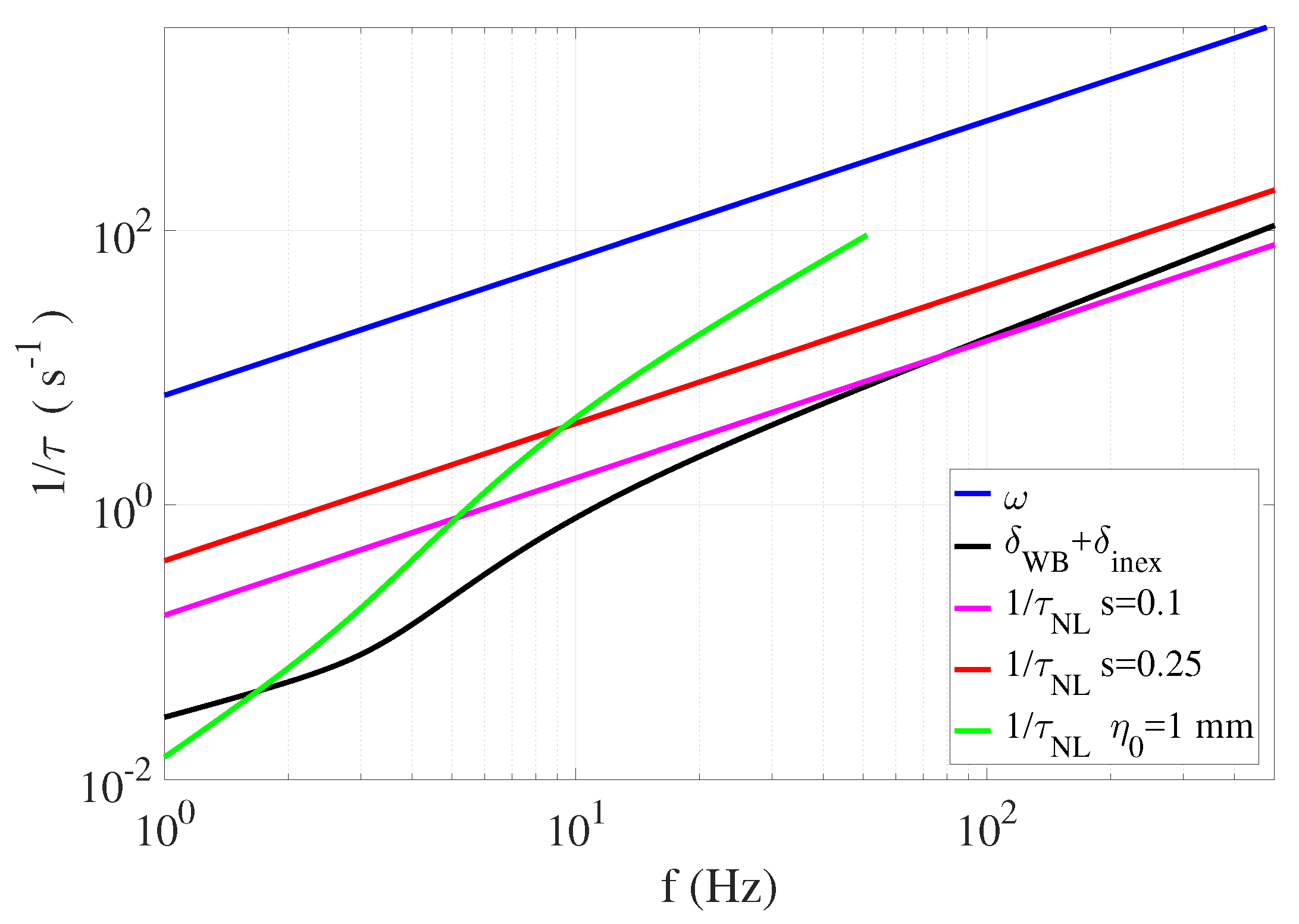
4. Orders of Magnitude of the Damping of Gravity–Capillary Waves and Consequences for Time Scale Separation

We provide some orders of magnitude of the damping rates for a typical gravity–capillary wave experiment. We consider water as liquid with a surface tension γ = 60 mN/m, a density ρ = 998 kg m 3 , and a kinematic viscosity ν = 10 6 m 2 s 1 . This value of γ = 60 mN/m corresponds typically to experiments in presence of surface contamination, when the measured dispersion relation is used to fit γ . The orders of magnitudes are slightly dependent on the exact values of these parameters. We first consider a gravity wave of frequency f = 5 Hz generated in a rectangular plexiglass tank of width W = 160 mm and filled to a height H = 50 mm with water, which gives 1 / δ = 55 s, 1 / δ W B = 40.3 s, 1 / δ i n e x = 5.29 s, and 1 / δ L = 0.284 s (for an amplitude η 0 = 1 mm and K = 0.6 ). The total damping rate is given by δ T = δ W B + δ i n e x + δ L because the clean surface and the inextensible film model correspond to two different and incompatible conditions for the velocity field at the free surface, the cancellation of tangential stresses for the first, and the nullity of the tangential velocity. We obtain 1 / δ T = 0.27 s; the dissipation due to the contact line’s effect is, thus, dominant for these experiments. However, the model of Miles for describing the dissipation for a sliding contact line remains approximate. Then, we consider a capillary wave of frequency f = 15 Hz propagating in the same tank. In that case, there is no estimation of the dissipation at the contact line for waves whose wavelength are very small in front of the tank size. Moreover, a recent experiment demonstrates that the reflection coefficient of such a wave depends strongly on the wetting conditions at the wall [69]. An increased dissipation at the reflection due to the motion of the meniscus should occur. This effect has not been investigated in the literature and would deserve supplementary experiments. Then, we have 1 / δ = 2.73 s, 1 / δ W B = 23.3 s, and 1 / δ i n e x = 0.681 s, which gives a total damping time of 1 / δ T = 1 / ( δ W B + δ i n e x ) = 0.662 s. The condition of weak damping of the surface waves writes ω = 2 π f δ T . In that case, ω = 94.3 s 1 and δ T = 1.51 s 1 . The separation of scale is, thus, valid for the linear propagation of the surface waves. This condition remains true even at very high frequencies for fluids whose viscosity is similar or less than water. The dissipation has, thus, a secondary influence in the propagation of the surface waves. A wave decreases typically on a damping length or attenuation length l a t t = v g / ( δ W B + δ i n e x ) , but keeps a structure close to the one derived for an inviscid fluid. This length is plotted as a function of the frequency of the wave in Figure 6a. This length decreases with frequency and is about 10 cm for f = 20 Hz and 3 cm for f = 100 Hz. Consequently, in this domain belonging to capillary waves, the waves propagate on a distance of few centimeters from the wave-maker, except if they are produced homogeneously, for example, by using the Faraday instability [70]. In fact, for frequencies above 10 Hz, the waves propagate on a distance equivalent to 10 wavelengths or less on all the capillary ranges. Therefore, realizing the homogeneous field of capillary waves is difficult experimentally. Even in the intermediate regime between gravity and capillary waves, 7 < f < 15 Hz, the dissipation is considerable. This strong damping rate explains why, in nature, the capillary waves are restricted to wave-trains of a few wavelengths, i.e., ripples.
We consider now the nonlinear effects in a broad approach. If we consider the case of three-wave interactions, a typical nonlinear time can be derived from Equation (36). This time corresponds to the typical time of evolution of the wave envelope due to the three-wave interaction. We define, thus, 1 / τ N L = 1 4 η 0 k ω , with η 0 being the typical amplitude of the wave. This estimation is valid for waves of close frequencies. The exact value depends on the precise angular frequencies ω s composing the triad, and on the initial amplitudes A s , but the discussion would remain the same. In Figure 7, we compare the inverse of this nonlinear time 1 / τ N L to ω and the total damping rate. In a first step, we can estimate 1 / τ N L = 1 4 s ω , where s = η 0 k is the wave steepness. We display the cases for s = 0.1 and s = 0.25 , which do not correspond already to a weakly nonlinear situation. For the first, the curve intersects the damping rate curve for f 60 Hz, which means that three-wave interactions cannot occur at high frequencies. The wave is damped in the same amount of time as the one needed to be significantly modified by the nonlinear interaction. For s = 0.25 , the curve remains above the damping rate curve, but there is not a real scale separation between δ T , 1 / τ N L and ω . For example, at f = 15 Hz, 1 / τ N L = 5.9 s 1 , which is four-times δ T and 1 / 16 of ω . In a second step, we estimate the nonlinear time 1 / τ N L = 1 4 η 0 k ω differently by choosing η 0 = 1 mm, which seems more relevant at low frequencies but less in the capillary wave regime, where the corresponding steepness would be very large. In that case, in the range [ 0 , 10 ] Hz, the occurrence of a three-wave nonlinear interaction with a moderate steepness and a satisfying scale separation becomes possible. Therefore, for capillary surface waves and gravity waves close to the crossover, the viscous dissipation cannot be neglected in the study of the nonlinear wave interactions. These orders of magnitude have been derived for a contaminated free surface, for which the viscous dissipation is strongly increased. Finally, we argue that in natural situations at the surface of seas, lakes, and rivers, the free surface is always contaminated. The capillary ripples which are seen in everyday life are, thus, always strongly influenced by the enhanced surface dissipation due to the presence of surfactants.

5. Consequences of Wave Dissipation on Finite Size Effects

We have shown previously that gravity–capillary waves of frequencies above 10 Hz are subjected to a significant damping due to viscous dissipation, when the free surface is contaminated with surfactants (nearly always in laboratory experiments with water and in the field). Using a simplified model, we show the effect of the wave decay on the spatial distribution of the waves in linear regime. In particular, we demonstrate that the viscous wave dissipation limits or even prevents the wave quantization phenomenon, which is expected when the wave field is confined in a finite-sized container. This study has been published previously in one of our previous articles [71], and is reproduced here with a correction which does not change the conclusions. We consider a one-dimensional domain along O x between x = 0 and x = L , limited by rigid walls. An initial monochromatic surface wave of wavenumber k and angular frequency ω is continuously injected in x = 0 , with an amplitude A 0 . The motion of the wall creating the wave is supposed as sufficiently small to be neglected. Due to linear viscous dissipation, the wave decays spatially with a rate β = 1 / l a t t . The wavelength is supposed to be small in front of the typical dissipation length 1 / β and the system length. The initial free-surface deformation writes, using complex formalism, η 0 ̲ ( x , t ) = A 0 e β x e i ( ω t k x ) . When the wave reaches the position x = L , to vanish the horizontal velocity at any time, it can be shown that a reflected wave labelled 1 is created, propagating backward with the same amplitude as the incident wave. The wave 1 is then reflected in x = 0 to create the forward wave 2, and so on and so forth. The total free-surface deformation can be expressed in a stationary regime by the sum:
η ̲ ( x , t ) = A 0 e β x e i ( ω t k x ) + A 1 e β ( L x ) e i ( ω t + k x ) + A 2 e β x e i ( ω t k x ) + A 3 e β ( L x ) e i ( ω t + k x )
with the following relations between the wave amplitudes:
A 0 e β L e i k L = A 1 e i k L ,
  A 1 e β L = A 2 ,
A 2 e β L e i k L = A 3 e i k L ,
Then, the amplitudes of forward and backward waves are written, respectively, as:
A 2 p = A 0 ( e 2 β L e 2 i k L ) p , A 2 p + 1 = A 1 ( e 2 β L e 2 i k L ) p .
Consequently, η ̲ can be seen as the sum of two geometric sequences with the same ratio e 2 β L e 2 i k L . By taking the infinite limit in the sum, such as in a N-wave interference problem, we obtain:
η ̲ ( x , t ) = A 0 1 e 2 β L e 2 i k L e β x e i ( ω t k x ) + e β x e β ( L x ) e 2 i k L e i ( ω t + k x ) .
The space and time average amplitude is obtained by taking the square root of the product of η ̲ with its complex conjugate. After some algebra, we obtain:
η = η ̲ η ̲ = 1 exp ( 2 β L ) 2 β L 1 / 2 A 0 2 1 + e β L 1 e β L 1 + 4 e β L ( 1 e β L ) 2 sin 2 ( k L ) 1 / 2 .
The dependency of η with the wavenumber k is plotted in Figure 8a for varying dissipation levels. The attenuation length l a t t = 1 / β is used to facilitate the comparison with the system size. The solution is analogous to the resonance of a cavity in which a wave is injected. When dissipation is small or l a t t is large, resonance occurs for the eigenmode of the system given by the condition k = p π L , with p being a positive integer. The peak amplitudes saturate due to the non-zero dissipation. If dissipation is increased, the attenuation length decreases and the width of the peaks increases, as can be seen in Figure 8b. For l a t t 0.4 L , the width becomes comparable with the distance between peaks, and they become indistinguishable. η is, thus, nearly flat for l a t t = 0.2 L in Figure 8a. These results can be applied to the experimental situation by taking L = 0.165 m, using the dispersion relation (Equation (19)), and expressing l a t t = v g / δ i n e x given by Equation (72). The average wave amplitude η is displayed as a function of the frequency of the injected wave in Figure 8c. Resonance, due to the finite size of the tank, becomes insignificant for f > 10 Hz, and is, thus, in the capillary regime. This simple model shows that the quantization of the wavenumbers in a finite-sized domain is a limit result for vanishing viscous dissipation in presence of forcing. The eigenmodes are indeed stationary wave solutions in a free regime (without forcing by a wave-maker), and are obtained by applying a Helmholtz equation to the domain. With forcing and small dissipation, these modes are created physically by an interference process due to the multiple reflections of the waves on the domain boundaries. In presence of significant dissipation, the container modes are less defined, or even disappear completely, when the waves are damped too much during their propagation to feel the boundaries. Experimentally, energy dissipation at the reflection in a capillary wave regime, due to the motion of the contact line, increases the total amount of dissipation even more, and the wave-mode quantization becomes even less observable. Moreover, we note that, in a recent laboratory study of the confinement of gravity laboratory waves in the range 1 < f < 8 Hz, the discretization is reported in the transverse direction only for a sufficient lateral confinement [72]. Only the nonlinear broadening of the modes is taken into account. An estimation of the mode widening due to viscous dissipation may be useful to explain the absence of discretization for a too-large distance between the walls.

6. Consequences of Dissipation on Three-Wave Interactions between Surface Waves

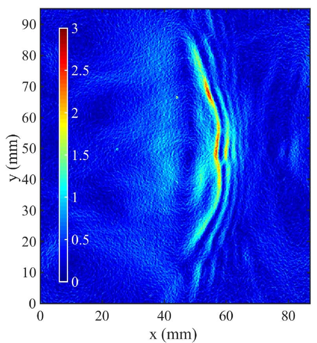
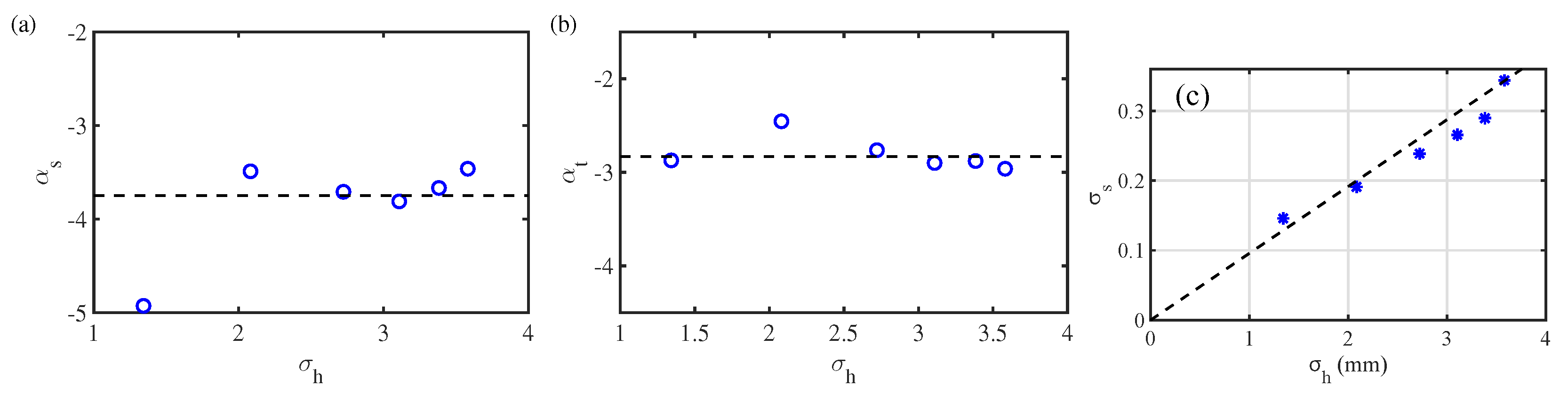
6.1. Experimental Study of Three-Wave Interactions of  Waves

In two previous articles [42,63], we studied experimentally the three-wave interaction mechanism for non-collinear injected waves and frequencies in the range [ 10 , 50 ] Hz, i.e., for waves whose main restoring force is the capillarity, but for whom the gravity is not completely negligible. The configuration corresponds to Figure 9. Using a space-time measurement, the diffusing light photography method [73], we evidenced in Haudin et al. [63] that in resonant conditions, the crossing of two mother wave trains (1 and 2) of frequencies f 1 and f 2 creates a daughter wave (3) consistent with the three-wave resonant interaction theory [8,14,43]. We verified experimentally the resonant conditions:
f 1 + f 2 = f 3 and k 1 + k 2 = k 3 .
However, the resonant conditions associated with the linear dispersion relation imposes a specific angle between the mother waves once the frequencies f 1 and f 2 are chosen. In these conditions, we have shown that the amplitude of the daughter wave results from the balance of nonlinear growth and viscous dissipation [63]. From the amplitude equations of the triad component [15], we obtain for the daughter wave 3:
v g 3 a 3 / ξ = δ 3 a 3 + a 1 a 2 γ 3 sin ϕ ,
with v g 3 being the group velocity of wave 3, ξ being the spatial coordinate along the wave 3, a i being the wave amplitude of the component of the triad (dimension of a length), ϕ = ϕ 1 + ϕ 2 ϕ 3 being the phase between the waves, and γ 3 being the interaction coefficient or the nonlinear growth rate, which can be computed analytically [43]. This equation can be integrated with the hypothesis of constant mother wave amplitudes and the boundary equation a 3 ( ξ 0 ) = 0 :
a 3 ( ξ ) = γ 3 sin ϕ δ 3 a 1 a 2 1 exp δ 3 v g 3 ξ ξ 0
At short distances or for weak dissipation, a 3 grows linearly with ξ , but saturates for sufficient distances to a 3 sat ( ξ ) = γ 3 sin ϕ δ 3 a 1 a 2 , resulting from the competition between nonlinear growth and dissipation. The factor K ( ξ ) expresses the spatial dependency of the wave 3:
K ( ξ M ) = 1 exp δ 3 v g 3 ξ M
This analysis has been validated by dedicated local measurements, such as those depicted in Figure 10. We obtained, for the triad (15, 18, 33) Hz, an experimental estimation of the nonlinear interaction coefficient γ 3 e x p = 1.46 × 10 4 m 1 s 1 , which is 20 % more than the theoretical value γ 3 = 1.24 × 10 4 m 1 s 1 . For the triad (16, 23, 39) Hz, we find γ 3 , e x p = 1.22 × 10 4 m 1 s 1 , which is 13 % less than the theoretical value γ 3 , t h = 1.41 × 10 4 m 1 s 1 . The orders of magnitude are satisfying given the hypotheses made, showing that the dissipation is required to explain the amplitude of the capillary waves produced by wave interactions.

6.2. Forced Three-Wave Interactions of Gravity–Capillary Waves

Then, in a second article [42], we studied the three-wave interaction mechanism of gravity–capillary waves, in the case where the angle between the mother wave is not the resonant angle α 12 r . Surprisingly, we found that daughter wave 3, verifying the resonant conditions, is always detected, but the wavenumber k 3 is slightly shifted from the linear dispersion relation. Examining the nonlinear perturbation of the free surface at the lowest order [41], we proposed a model explaining our observations as forced three-wave interactions. According to the amplitude equations, we found that the quadratic nonlinear response always allows a three-wave interaction for all angles α 12 between the mother waves, with a maximal response for α 12 = α 12 r . In the resonant case, the wave 3 grows with the origin (begining from the interaction zone), and at long distances, it diverges in absence of dissipation such as the resonance of a forced oscillator. In contrast, when α 12 α 12 r , the amplitude of the wave 3 is spatially modulated, similarly to the case of non-resonant interactions (see Section 2.7), as is shown in Figure 11. The angular band-pass response defined as the full width at half maximum decreases with the propagation distance ξ and increases with the dissipation rate of the wave 3.
These predictions have been confronted with dedicated experiments, as shown in Figure 12. The measurements are in reasonable agreement with the model and validate it qualitatively. The deviations occur likely because the model supposes, again, a constant mother wave amplitude to be solvable analytically.

6.3. Energy Flux for a Non-Resonant Three-Wave Interaction

Here, we provide a theoretical estimation of the energy flux created by a single three-wave interaction in a non-resonant case. In most of the studies, non-resonant interactions are ignored. However, in presence of dissipation, they can contribute on average to the global energy flux from large to small scales for capillary–gravity waves, due to the finite lifetime of the waves. Here, we consider a simplified case of a triad, where a daughter wave is forced by two homogeneous and constant mother waves. We supposed a homogeneous wave field for all the components of the triad, although we know that this hypothesis is not experimentally realistic for surface waves. For a non-resonant triad, an amplitude equation can be written for the wave envelopes A i under this form:
d A 3 d t + δ 3 A 3 = i γ 3 A 1 A 2 e i δ ω t ,
where δ 3 is the linear dissipation coefficient of the wave 3, γ 3 is the interaction coefficient, and δ ω is the mismatch to the exact resonance in frequency. The resolution of this differential equation gives, using the initial condition A 3 ( t = 0 ) = 0 :
A 3 ( t ) = γ 3 A 1 A 2 δ ω i δ 3 e i δ ω t e δ 3 t .
Then, we compute the daughter wave intensity as I 3 = 1 2 A 3 A 3 :
I 3 ( t ) = ( γ 3 A 1 A 2 ) 2 2 ( δ ω 2 + δ 3 2 ) 1 + e 2 δ 3 t 2 e δ 3 t cos ( δ ω t ) .
The wave energy per surface and density unit reads E 3 = 1 2 ω 3 v ϕ , 3 I 3 [43]. In absence of dissipation, the associated energy flux transmitted by the mother waves to the daughter wave is defined as ϵ 3 = d E 3 d t . Here, as shown previously in Section 6.1, the dissipation can saturate, in a stationary regime, the energy flux; we must then include the damping of the energy in the expression of the flux ϵ 3 = d E 3 d t + 2 δ 3 E 3 .
After some algebra, we find:
ϵ 3 ( t ) = ω 3 2 2 k 3 ( γ 3 A 1 A 2 ) 2 δ ω 2 + δ 3 2 δ 3 + e δ 3 t δ ω sin ( δ ω t ) δ 3 cos ( δ ω t ) .
The time evolution of ϵ 3 , rescaled by ( γ 3 A 1 A 2 ) 2 , is displayed in Figure 13 for a few values of δ ω . The parameters of the daughter wave correspond to a capillary wave of frequency f 3 = 33 Hz, wavenumber k 3 = 834 m 1 , and dissipation rate δ 3 = 4.25 s 1 . The energy flux grows with time to saturate to a finite value whose amplitude decreases with the distance to the exact resonance δ ω . A few oscillations are visible for the largest values of δ ω . They are characteristic of non-resonant interactions, but for this level of dissipation, they are significantly damped. In the limit δ 3 = 0 , we note that ϵ 3 ( t ) = ω 3 2 2 k 3 ( γ 3 A 1 A 2 ) 2 δ ω 2 δ ω sin ( δ ω t ) . The average flux is, thus, 0, except in the limit of the exact resonance, when δ ω 0 , where ϵ 3 ( t ) ( γ 3 A 1 A 2 ) 2 2 t . The energy flux for a stationary forcing grows linearly with time because the energy of the daughter wave increases in t 2 with time.
Coming back to the dissipative case, Equation (89) shows that the flux converges towards a finite value over a long period of time:
ϵ 3 = ω 3 2 2 k 3 δ 3 ( γ 3 A 1 A 2 ) 2 1 + ( δ ω / δ 3 ) 2
We plot, in Figure 13b, ϵ 3 / ( γ 3 A 1 A 2 ) 2 as a function of δ ω for a few values of δ 3 . We find, again, a classic resonance phenomenon: the energy transfer is maximum for δ ω = 0 and the bandwidth of the resonance is proportional to the dissipation δ 3 , which justifies the use of the resonance terms for wave interactions. According to this simple model, the contributions of the non-resonant interactions to the energy flux is non-negligible, i.e., ϵ 3 is larger than 1 / 10 of the value obtained at the resonance δ ω = 0 if δ ω 3 δ 3 . Therefore, for real systems with dissipation, the non-resonant interactions must be taken into account if the mismatch to the resonance in angular frequency is of the order of the damping rate due to dissipation. The distinction between non-resonant and quasi-resonant interactions is, then, in some ways arbitrary.
To conclude this section, whereas the study of resonant interactions among waves started around 1960, we have shown that, in experiments where the dissipation is non-negligible, the physical description is incomplete. Experimentally, we evidence the generation of capillary waves by the three-wave resonant mechanism, with an interaction coefficient which is reasonably close to the one given by the weakly nonlinear inviscid theory. However, the significant dissipation implies important changes. First, the daughter waves are saturated by the viscosity instead of by the nonlinear coupling with other waves. Secondly, the amplitude of the mother waves decays by viscous damping, making the application of the models more questionable. Then, the bandwidth response of the free surface to excitations is increased by the dissipation and by the short distance of observation. The free surface being less selective, we can experimentally observe waves created by the forced three-wave mechanism not obeying the dispersion relation, or waves generated by a non-resonant interaction mechanism. This statement has important consequences for the statistical study of interacting waves, the wave turbulence discussed in the next section. To improve the physical description of the problem of nonlinear interacting waves in presence of dissipation, the development of dedicated numerical simulations will be a good complement. Likely more mathematically involved, substantial progress on this problem would consist of building a weakly nonlinear theory of interacting waves, taking into account the dissipation. For surface waves, a starting point could be to decompose the velocity field into an irrotational part given by the velocity potential and a solenoidal part (divergence free) derived from the curl of a vector field, which is called the Helmholtz decomposition and is used to compute the wave damping rates [24]. Using this method, Dias et al. have shown that in cases of weak damping, the nonlinear Schrödinger equation describing the envelope dynamics of surface gravity waves is simply modified by adding a simple classic damping term [31].

7. Consequences of Dissipation on the Capillary Wave Turbulence

Wave turbulence consists in the statistical study of a large set of dispersive waves randomly distributed and in nonlinear interactions, like in the disordered sea states depicted in Figure 14.
In the theoretical approach, the wave field is decomposed into modes in the Fourier space, which interact and exchange energy with each other through nonlinear wave interactions. If these interactions are sufficiently weak to be treated as perturbations, the statistical description of the wave field in the Fourier space becomes possible. The wave turbulence theory or the weak turbulence theory started in the 1960s, when power law spectra were obtained by Vladimir Zakharov [74] for water waves [75,76] or magnetohydrodynamic waves in plasmas [77], expressing the self-similar transfer of a conserved quantity through the scales. Using a Hamiltonian approach and making some hypotheses of the randomness of the wave field, in particular the random-phase approximation (this hypothesis appears robust in experiments and simulations because the nonlinear dynamics often randomizes the wave field), a kinetic equation expresses the dynamical evolution of the number of quasi-particles n k occupying the level of the wave vector k due to the nonlinear wave interactions [13]. Assuming a dispersion relation under the form of a power law, Zakharov was able, using a conformal transformation, to find analytically two stationary solutions of the kinetic equation under the form of power law spectra. A first one, the Rayleigh–Jeans spectrum, corresponds to the thermodynamic equilibrium, without global energy transfer on average. The second solution is out of the thermodynamic equilibrium, describing the turbulent regime where a conserved quantity, often an energy flux, is transferred from an injection scale towards a dissipation scale; this is the Kolmogorov–Zakharov spectrum. Such spectra have been derived for three-wave interactions or four-wave interactions in nearly all physical situations where nonlinear waves propagate, the medium being isotropic or anisotropic. Independently in the same period, David J. Benney, Philip G. Saffman, and Alan C. Newell [78,79] contributed to the statistical closure of the hierarchy of the kinetic equations, and Klaus Hasselmann proposed a statistical approach of oceanic gravity waves interacting by four-wave interactions but without deriving the constant energy flux spectra [80]. For a complete treatment and further information, we refer the reader to consult the reference books [12,13] and rewiews [81,82].
The observation of wave turbulence requires, thus, the condition of weak nonlinearity, which supposes a small, dimensionless, nonlinear parameter (the steepness for water waves). This condition is judiciously expressed in the temporal space by expressing that the typical time of a nonlinear interaction τ N L must be large compared to the linear time τ L = 1 / ω , i.e., a wave must be able to interact during several periods to conserve its linear structure, before its energy is transferred to other wave modes. In presence of dissipation, the wave damping time τ d i s s must, in addition, be large enough to permit a sufficient number of interactions in order to randomize the wave field and reach the statistical regime. A necessary condition of existence of the wave turbulence reads, then, as a time-scale separation condition: τ L τ N L τ d i s s . We discussed previously, in Section 4, this condition in the case of gravity–capillary waves subjected to three-wave interactions.
The turbulence of water surface waves constitutes indeed the most obvious case of the application of the wave turbulence theory. It has deserved several careful experimental investigations since the end of 20th century (see the review works of S. Nazarenko and S. Lukaschuk [82] and of E. Falcon and N. Mordant [83] for a recent overview of the experimental literature). The wave turbulence theory predicts analytic expressions of spectra corresponding, for the non-equilibrium solutions, to a transfer of a conserved energy flux ϵ , from an injection scale to a dissipative smaller scale for the direct cascade. Spectra are expressed as power laws of k in space and of ω in time with known exponents. In the case of pure gravity waves, for which four-wave resonant interactions are the main nonlinear wave interaction process, the power spectra of the wave elevation η ( x , t ) read, in space and time [76]:
    S η ( k ) = C K Z ( g k ) ϵ 1 / 3 g 1 / 2 k 5 / 2 ,
S η ( ω ) = C K Z ( g ω ) ϵ 1 / 3 g ω 4 .
In contrast, for pure capillary waves, where nonlinear wave interactions occur at the first order through three-wave resonant interactions, the theoretical spectra are expressed as [75]:
S η ( k ) = C K Z ( c k ) ϵ 1 / 2 ( γ / ρ ) 3 / 4 k 15 / 4 ,
S η ( ω ) = C K Z ( c ω ) ϵ 1 / 2 ( γ / ρ ) 1 / 6 ω 17 / 6 .
A complete derivation for pure capillary waves can be found in the recent review of S. Galtier [84]. As the dispersion relation must be written as a power law in the theoretical derivation, there is no prediction for gravity–capillary waves in the vicinity of the crossover k c = 1 / l c . Note that the spectra can be deduced from the dimensional analysis and the dispersion relation, knowing that the scaling of ϵ is set by the order of the resonant interaction (an N waves process implies an energy flux scaling under the form: ϵ 1 / ( N 1 ) ) [85], but without the values of the dimensionless Kolmogorov–Zakharov constants C K Z . At the cost of some algebra work, wave turbulence theory provides, indeed, the values of the constants for pure gravity [86] and pure capillary [40,87] waves. Contrary to gravity waves, which admit an inverse cascade of wave action [13], an out-equilibrium spectrum corresponding to an inverse cascade is not possible for capillary waves. The equilibrium solution of wave turbulence can explain the spectrum filling for a forcing at small scales [88]. The validity of the wave turbulence theory for the direct cascade of pure capillary waves has been extensively tested numerically, using simulations of the Zakharov Hamiltonian formulation of water waves [40,89], a direct numerical simulation in the context of potential flow (Euler equation) [87,90,91], and direct numerical simulations of the Navier–Stokes equation with a liquid–gas interface [92].
Experimentally, in the capillary wave regime, several independent studies reported observations of the spectra exponents given by the wave turbulence theory [73,93,94,95,96,97]. Most of the previous laboratory works have tried to isolate capillary wave turbulence from the gravity wave regime by using a parametric forcing [73,93,94,97,98,99], by operating under microgravity [96], or by studying waves at the interface between two fluids of the same density [100]. However, capillary waves occurring in natural situations, at the free surface of open spaces of water, are mainly generated from gravity waves, themselves produced by wind action [10]. Three-wave interactions for frequencies close to the gravity–capillary crossover are indeed prone to produce capillaries from gravity waves [5,101]. Previous studies using random gravity waves to generate a turbulent cascade of capillary waves [95,102,103,104,105] showed a good agreement of the spectral exponents with the predictions of wave turbulence theory, although the crossover between gravity and capillary waves is not described by wave turbulence theory. However, we showed, in Section 4, that for the turbulence of capillary waves, the condition of time-scale separation is hardly met due to the significant level of dissipation occurring in most laboratory experiments with water and in natural conditions. Our simple estimation shows that a wave steepness s larger than 0.1 is necessary to overcome the dissipation in the capillary regime. Consequently, in these conditions, the capillary wave turbulence does not occur in weakly nonlinear regimes and the time-scale separation remains limited.

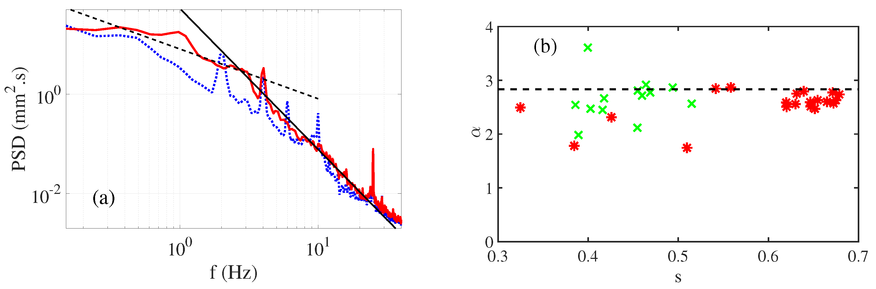
7.1. Capillary Wave Turbulence Forced by Gravity Waves

Using the diffusing light photography method, we performed an extensive space-time characterization of the capillary wave turbulence forced by capillary waves [71,104]. In that case, the forcing generates random gravity waves in the frequency range [ 4 , 6 ] Hz, which creates capillary waves by nonlinear interactions, mainly by the generation of parasitic wave trains (Figure 15). After reconstruction of the free-surface dynamics, the spatial power spectra and the time power spectra are computed (Figure 16). For sufficient forcing amplitude, we report power law spectra in the capillary wave range, whose exponents (Figure 17) are in very good agreement with the predictions of the wave turbulence theory (Equation (94)). The power law spectra extend from the gravity–capillary crossover scale λ c 15.5 mm towards a dissipative scale λ d ; below that, the viscous dissipation overcomes the nonlinear interactions. λ d decreases with the forcing amplitude to reach λ d 2.1 mm at highest forcing. As a consequence of dissipation, the turbulent cascade of capillary waves is, thus, limited to barely one decade. Moreover, the power law spectra are only observed when the typical wave steepness σ s (measured directly as the standard deviation of the surface deformation gradient | | η | | ) exceeds a sufficient level of about 0.15 . The highest steepness s = 0.34 is set to remain below the breaking of the forcing gravity waves in order to keep a monovalued free surface. Therefore, in agreement with the previous discussion, the observed capillary wave turbulence regimes do not satisfy the hypothesis of weak nonlinearity due to the significant viscous dissipation of capillary waves. The importance of viscous dissipation has been also underlined with local measurements in another experimental work studying the decaying regime of capillary wave turbulence forced by gravity waves [103]. Although the time power spectra display the expected power law in f 17 / 6 , the amplitude of wave modes decreases exponentially with time and not as power laws. These decays are explained by the viscous decay of the largest wave modes according to the inextensible film model (Equation (72)), which shows that the dissipation occurs at all scales and that the energy flux is not really conserved through the scales, in agreement with local [106] and space-time [71] measurements. This statement contradicts the hypotheses of the wave turbulence theory, which supposes negligible dissipation in the inertial range to attribute the power law spectra to the conservation of the energy flux ϵ through the scales.
Therefore, using the space-time characterization of the wave field [71,104], we verified that these regimes of capillary wave turbulence beyond the hypothesis of weak turbulence correspond really to a wave turbulence phenomenon. The wave phases are indeed uncorrelated, justifying the statistical treatment of the wave field using power spectra. The maxima of space-time power spectra are gathered along a curve forming the experimental dispersion relation, close to the linear dispersion of the gravity–capillary waves, but with a notable nonlinear shift. The nonlinear time is experimentally estimated from the width of the dispersion relation and a limited time scale separation is found ( τ N L τ d i s s / 8 and τ N L 5 / ω ). By performing a bicoherence analysis, strong occurrence of three-wave interactions is detected, showing that the spectrum is built by three-wave interactions, but for a large part far from the resonance. Non-resonant interactions are indeed possible given the small size of the experiment and the significant width of the dispersion relation due to dissipation and non-linearity. We show also that the power law spectra are built on average by intermittent bursts of wave energy, corresponding to the generation of parasitic capillary wave trains. Parasitic capillary wave-generation corresponds indeed to a direct transfer of energy from a steep and long gravity–capillary wave towards a capillary wave, which has the same phase velocity as the longer wave. This non-local and one-dimensional mechanism is assumed to occur at quite-high non-linearity for steepnesses s larger than 0.1 [23,48,107] and is, thus, not considered as a weakly nonlinear mechanism. However, few studies show that they could be considered in first approximations as a combination of three-wave non-resonant interactions and, in a lesser extent, four-wave non-resonant interactions [108,109]. Then, the exponents of the power spectra result likely from the dimensional analysis prediction of turbulent wave spectra [85], in presence of capillary waves following the linear dispersion relation and three-wave interactions. The scaling on the energy flux is indeed determined by the order of the wave interactions. This “strong” regime of capillary wave turbulence differs in principle from the weakly nonlinear scenario of the theory, when the time scale separation is large and the interactions are local in the scales, i.e., involving close wavenumbers. We note that, using purified and filtered water to keep a dissipation level close to the case of uncontaminated water and a lower steepness level (below 0.1 ), the capillary cascade with the exponent 17 / 6 is not generated [44]. Similar experiments [102] show that the turbulent capillary wave spectrum is observed only for the high forcing (regime I), when the steepness is of the order of 0.3 . For the works using mercury as a fluid of lower kinematic viscosity and a local capacity wave probe [95,110], due to the smaller dissipation, the capillary wave cascade is observed for steepness of order 0.1 . Moreover, in these conditions, the signal displays bursts of capillary wave trains on steep gravity waves [111], which resemble the generation of parasitic capillary waves. We note also that in other systems, such as gravity surface waves [55,105,112] or bending waves in metallic plates [113,114], the exponent of wave spectra decreases when the dissipation level is increased or the forcing amplitude is decreased. Here, the independence of the spectral exponent with the forcing for the “strong” regime of capillary wave turbulence may be due to the high level of nonlinearity and the non-locality of interactions, but a definitive explanation remains to be provided.

7.2. Turbulence of Pure Capillary Waves in Microgravity

By performing experiments in weightlessness, without gravity, wave turbulence for pure capillary waves can be achieved. Numerical simulations [89,90,92] demonstrated the validity of the predictions of the wave turbulence theory only for pure capillary waves without gravity. The theory supposes power law spectra to fulfill the condition of scale invariance in turbulent regimes, and this hypothesis cannot be met in presence of two restoring forces acting at different scale ranges. The effect of the gravity–capillary crossover is, in fact, not completely understood for the turbulence of surface waves. Moreover, in microgravity, capillary waves can propagate on a larger range of scales because the largest wavelength is now set by the container size and is no more given by the balance between gravity and capillarity, i.e., λ c = 2 π γ / ( ρ g ) 15.5 mm on Earth’s surface. Therefore, we expect a larger extension of the cascade of capillary waves. A first experimental work [96] has been performed using parabolic flights, achieving microgravity phases of 22 s. Using a cylindrical Plexiglas container partially filled with ethanol, the liquid forms a layer wetting the internal wall of the container in weightlessness and the fluctuations at the air/liquid interface are recorded by means of a capacitive probe. In that case, a power law spectrum with an exponent equal to 3 and close to the predicted exponent 17 / 6 is reported on two decades. In order to characterize capillary wave turbulence over longer durations, an experiment has been recently performed with a similar protocol in the International Space Station [115]. The container is now a polycarbonate sphere of internal radius 100 mm and filled with water at a ratio of 30% (Figure 18). The forcing is achieved by means of a rotating arm prescribing small oscillations, which can be sinusoidal or random. The fluctuations of the air/liquid interface are recorded using two capacitive probes. The wetting of polycarbonate by water is not as good as the wetting of plexiglass by ethanol; therefore, for strong agitation of the sphere, we observe air bubbles and even some de-wetting events. Nevertheless, after averaging over 400 s, the recorded power spectra show, especially for the second sensor, a decay at high frequency that is compatible with the power law in f 17 / 6 over one decade (Figure 19). Again the high-frequency part of the spectra can be interpreted as a turbulent cascade of capillary waves. However, once the steepness s is indirectly evaluated from the time spectrum and the linear dispersion relation, we realize that these turbulent regimes occur for high values of the steepness between 0.3 and 0.5 . These regimes are strongly nonlinear but remain below the breaking threshold of pure capillary waves, which is 4.59 [34]. Similar to the experiments described in the previous part, the capillary wave turbulence is not found in a weakly nonlinear regime, and the simplest explanation of the experimental spectra relies likely on the dimensional analysis. Due to the thin water layer of few millimeter, the wave dissipation caused by the moving contact lines and the possible contamination of the water appears significant indeed. Further experiments performed in microgravity with more sensitive sensors and better wetting properties will be useful to better characterize the strong capillary wave turbulence evidenced here.

7.3. Discussion

The turbulence of capillary waves is often considered as an example of the success of the wave turbulence theory [81]. Our experiments demonstrate that this is not really the case due to the viscous dissipation. A significant level of nonlinearity is indeed needed to overcome the dissipation and to generate a turbulent cascade (see Section 4). The experiments in the International Space Station [115] demonstrate that, even in microgravity, the regimes of turbulence of capillary waves are also in a strong nonlinear regime.
In this section, we have considered some experiments studying the turbulence of capillary waves. We have demonstrated that the power law for the time spectrum in f 17 / 6 , predicted by the weakly nonlinear wave turbulence theory, is obtained experimentally for steepnesses larger than 0.1 in water—thus, for a significant level of nonlinearity. In these regimes, we observe well the propagation of waves, as the fluctuations of the free surface follows a dispersion relation (even with a nonlinear shift). Moreover, the wave statistic is sufficiently random to be in the validity domain of the random-phase approximation [71]. Therefore, these regimes can be described as a wave turbulence phenomenon resulting from the nonlinear interactions of numerous waves, but not in the conditions of the application of the weakly nonlinear theory. The nonlinearity level nevertheless remains below the one associated with the strongly nonlinear regime called the critical balance [13,85], where the energy flux is sufficiently large so that the linear time is equal to the nonlinear time. In this regime, waves cannot propagate anymore because their period is equal to the time needed for them to disappear by nonlinear wave interactions. Here, as the nonlinear waves interact mainly through the three-wave interaction mechanism and follow the dispersion relation, the dimensional analysis explains why the predictions of the weakly nonlinear theory are found in a non-weakly nonlinear regime.
As we have shown, due to the important viscous dissipation of capillary waves, a significant nonlinearity level is required to obatin a self-similar regime. As a consequence, the time scale separation between dissipative, nonlinear, and linear time is limited, always less than a decade. The number of successive interactions is consequently limited to a few orders of τ d i s s / τ N L . This is why the use of random forcing is necessary to achieve random statistics for the wave field. With a sinusoidal forcing, the succession of interactions is too small to randomize the wave field. Capillary wave turbulence experiments in microgravity constitutes one exception, because the waves of larger wavelengths than those on Earth dissipate less. We have also shown, for a turbulent wave system with a limited time scale separation and forced at large scale, that the energy transfer occurs by strong intermittent events, implying nearly all the spatial scales of the wave field in a fast time scale.
In our experimental study of the three-wave interaction mechanisms in Section 6.1 and Section 6.2, we have also demonstrated that the dissipation has important consequences on the interactions between waves. In the three-wave interaction mechanism, the daughter wave can be saturated by the dissipation, whereas in the picture of the wave turbulence, the amplitude of the daughter wave should be limited by its participation to other three-wave interactions initiating a cascade of interactions. Moreover, the finite lifetime of waves caused by the dissipation induces a widening of the dispersion relation. Non-resonant interactions (not following one of the resonant conditions) and forced interactions (not following the dispersion relation) then become possible. With the same reasoning, when the time scale separation is limited, i.e., τ N L / τ l i n 10 , in addition to resonant interactions, non-resonant and forced interactions should be taken into account in the wave turbulence phenomenon. In addition to the nonlinear broadening of the dispersion relation, preferential forced interactions which do not obey the dispersion relation may modify the central frequency. This effect may justify nonlinear shifts of the dispersion relation reported for capillary waves in some experimental works [44,71,104]. This observation nevertheless remains incompletely explained, and should warrant further investigations.
In the case of strong wave turbulence (but always with waves), another limit of the weakly nonlinear wave turbulence theory is also reached, due to the emergence of transient coherent structures. By definition, these structures break the hypothesis of uncorrelated phases between the components of the wave field. In the case of surface waves, they are often associated with steep gravity waves, which emit parasitic capillary waves or are close to breaking. Due to their non-sinusoidal shape, these waves contains numerous harmonics (bound or not) of a fundamental wavenumber. The role of these coherent structures remains also an open question in the study of the wave turbulence of surface waves [83].

8. Conclusions

In nature and in laboratory experiments, gravity–capillary water waves for frequencies larger than 5 Hz are often subjected simultaneously to significant nonlinear effects and important viscous dissipations. Although of prime importance to understand the small-scale dynamics of oceanic surfaces, this situation is not well addressed in the literature. In order to reach at least a qualitative understanding, in this review, we derive the theory of water waves from the fundamental equations and discuss the main physical mechanisms at the origin of wave dissipation and nonlinear effects. Due to the nearly unavoidable surface contamination for experiments with water, the capillary waves are strongly damped by viscosity and can propagate over about ten wavelengths. Consequently, nonlinear effects, whose amplitudes are quantified by the wave steepness, must be sufficiently strong to overcome the dissipation and be observable. Then, focusing on the three-wave interaction mechanism, we show that the viscous dissipation can saturate the interaction and allow non-resonant and forced interactions. These mechanisms are, however, most of the time neglected in the statistical description of water waves at small scales. Finally, we evaluate the consequences of the viscous dissipation on the turbulent regimes of capillary waves. Based on recent studies, we show that in experiments with water, where the capillary waves are generated from gravity waves, the power law spectra, in agreement with the predictions of the wave turbulence theory, do not meet the hypotheses of the theory. Specifically, the dissipation is not negligible in the capillary wave range and the nonlinearity level quantified by the steepness is not small. These "strong" wave turbulence regimes are not described by the weak nonlinear theory. Yet, some of the main results are explained by the dimensional analysis derived from this theory. Indeed, spatio-temporal spectra composing dispersion relations reveal wave propagation. Moreover, we have shown that the three-wave interaction mechanism is indeed at work in our experiments, with a greater contribution of the so-called non-resonant or forced interactions. The role of coherent structures, constituted in particular by the parasitic capillary waves, seems important in the dynamics of the free surface. Theoretical developments beyond the weakly nonlinear hypothesis would be useful, but appear to be hard to achieve. In contrast, numerical simulations of gravity–capillary waves at a liquid–gas interface incorporating a realistic dissipation seems reachable in the coming years, and could help to better characterize the small-scale dynamics of water waves and, maybe, explain the small-scale spectrum of a random sea.

Funding

This research received no external funding.

Institutional Review Board Statement

Not applicable.

Informed Consent Statement

Not applicable.

Data Availability Statement

Not applicable.

Acknowledgments

The author thanks Sébastien Aumaître (CEA Saclay) and Nicolas Mordant (LEGI, Grenoble Alpes University) for discussions. The co-authors of my previous articles specifically discussed here are also acknowledged: Annette Cazaubiel (MSC, Université Paris Cité), Luc Deike (Princeton University), Eric Falcon (MSC, Université Paris Cité), Stéphan Fauve (LPENS, École Normale Supérieure), Christophe Gissinger (LPENS, École Normale Supérieure), Florence Haudin (MSC, Université Paris Cité), Timothée Jamin (MSC, Université Paris Cité), and Guillaume Michel (IJLRDA, Sorbonne Université).

Conflicts of Interest

The author declares no conflict of interest.

References

  1. Feynman, R.P.; Leighton, R.B.; Sands, M. The Feynman Lectures on Physics, Volume I: Mainly Mechanics, Radiation, and Heat; Addison-Wesley: Reading, MA, USA, 1964. [Google Scholar]
  2. Bühler, O. Waves and Mean Flow, 2nd ed.; Cambridge University Press: Cambridge, UK, 2014. [Google Scholar]
  3. Philipps, O.M. Wave interactions—The evolution of an idea. J. Fluid Mech. 1981, 106, 21–227. [Google Scholar] [CrossRef]
  4. Craik, A.D.D. Wave Interactions and Fluid Flows; Cambridge University Press: Cambridge, UK, 1986. [Google Scholar]
  5. Hammack, J.L.; Henderson, D.M. Resonant interactions among surface water waves. Annu. Rev. Fluid Mech. 1993, 25, 55–97. [Google Scholar] [CrossRef]
  6. Philipps, O.M. On the dynamics of unsteady gravity waves of finite amplitude. Part 1. The elementary interactions. J. Fluid Mech. 1960, 9, 193–217. [Google Scholar] [CrossRef]
  7. Longuet-Higgins, M.S. Resonant interactions between two trains of gravity waves. J. Fluid Mech. 1962, 12, 321–332. [Google Scholar] [CrossRef]
  8. McGoldrick, L.F. Resonant interactions among capillary-gravity waves. J. Fluid Mech. 1965, 21, 305–331. [Google Scholar] [CrossRef]
  9. Hasselmann, K. Nonlinear interactions treated by the methods of theoretical physics (with application to the generation of waves by wind). Proc. R. Soc. A 1967, 299, 77–100. [Google Scholar] [CrossRef]
  10. Janssen, P. The Interaction of Ocean Waves and Wind; Cambridge University Press: New York, NY, USA, 2004. [Google Scholar]
  11. Boyd, R.W. Nonlinear Optics; Academic Press: Berlin, Germany, 2008. [Google Scholar]
  12. Zakharov, V.E.; L’vov, V.; Falkovich, G. Kolmogorov Spectra of Turbulence; Springer: Berlin/Heidelberg, Germany, 1992. [Google Scholar]
  13. Nazarenko, S. Wave Turbulence; Springer: Berlin/Heidelberg, Germany, 2011. [Google Scholar]
  14. McGoldrick, L.F. An experiment on second-order capillary gravity resonant wave interactions. J. Fluid Mech. 1970, 40, 251. [Google Scholar] [CrossRef]
  15. Henderson, D.M.; Hammack, J.L. Experiments on ripple instabilities, Part 1. Resonant Triads. J. Fluid Mech. 1987, 184, 15–41. [Google Scholar] [CrossRef] [Green Version]
  16. Szeri, A.J. Capillary waves and air-sea gas transfer. J. Fluid Mech. 1997, 332, 341–358. [Google Scholar] [CrossRef]
  17. Saylor, J.R.; Handler, R.A. Gas transport across an air/water interface populated with capillary waves. Phys. Fluids 1997, 9, 2529. [Google Scholar] [CrossRef]
  18. Hwang, P.; Burrage, D.M.; Wang, D.W.; Wesson, J.C. Ocean Surface Roughness Spectrum in High Wind Condition for Microwave Backscatter and Emission Computations. J. Atmos. Ocean. Technol. 2013, 30, 2168–2187. [Google Scholar] [CrossRef]
  19. Zhang, X. Enhanced dissipation of short gravity and gravity capillary waves due to parasitic capillaries. Phys. Fluids 2002, 14, 81. [Google Scholar] [CrossRef]
  20. Tsai, W.T.; Hung, L.P. Enhanced energy dissipation by parasitic capillaries on short gravity-capillary waves. J. Phys. Oceanogr. 2010, 40, 2435–2450. [Google Scholar] [CrossRef]
  21. Caulliez, G. Dissipation regimes for short wind waves. J. Geophys. Res. Ocean. 2013, 118, 672–684. [Google Scholar] [CrossRef]
  22. Melville, W.K.; Fedorov, A. The equilibrium dynamics and statistics of gravity-capillary waves. J. Fluid Mech. 2015, 767, 449–466. [Google Scholar] [CrossRef] [Green Version]
  23. Deike, L.; Popinet, S.; Melville, W.K. Capillary effects on wave breaking. J. Fluid Mech. 2015, 769, 541–569. [Google Scholar] [CrossRef] [Green Version]
  24. Lamb, H. Hydrodynamics; Springer: Berlin/Heidelberg, Germany, 1932. [Google Scholar]
  25. Whitham, G.B. Linear and Nonlinear Waves; Wiley-Interscience: Hoboken, NJ, USA, 1999. [Google Scholar]
  26. Mei, C.C.; Stiassnie, M.; Yue, D.K.P. Theory and Applications of Surface Waves; World Scientific Publishing: Singapore, 2005. [Google Scholar]
  27. Dias, F.; Kharif, C. Nonlinear gravity and capillary-gravity waves. Annu. Rev. Fluid Mech. 1999, 31, 301–346. [Google Scholar] [CrossRef] [Green Version]
  28. Deike, L. Etudes Expérimentales et Numériques de la Turbulence D’ondes de Surface. Ph.D. Thesis, Université Paris Diderot—Paris 7, Paris, France, 2013. [Google Scholar]
  29. Michel, G. Parois et Ondes de Surface: Dissipation, Effet Doppler et Interactions Non Linéaires. Ph.D. Thesis, PSL Reseach University, École Normale Supérieure, Paris, France, 2017. [Google Scholar]
  30. Segur, H. Lecture 1: Introduction to linear and non-linear waves. In Proceedings of the Nonlinear Waves; Buhler, O., Helfrich, K., Eds.; Woods Hole Oceanographic Institution: Woods Hole, MA, USA, 2009. [Google Scholar]
  31. Dias, F.; Dyachenko, A.I.; Zakharov, V.E. Theory of weakly damped free-surface flows: A new formulation based on potential flow solutions. Phys. Lett. A 2008, 372, 1297–1302. [Google Scholar] [CrossRef] [Green Version]
  32. Rajan, G.K.; Henderson, D.M. Linear waves at a surfactant-contaminated interface separating two fluids: Dispersion and dissipation of capillary-gravity waves. Phys. Fluids 2018, 30, 072104. [Google Scholar] [CrossRef]
  33. Jamin, T.; Gordillo, L.; Ruiz-Chavarría, G.; Berhanu, M.; Falcon, E. Experiments on generation of surface waves by an underwater moving bottom. Proc. R. Soc. A 2015, 471, 245–259. [Google Scholar] [CrossRef] [Green Version]
  34. Crapper, G.D. An exact solution for progressive capillary waves of arbitrary amplitude. J. Fluid Mech. 1957, 2, 532. [Google Scholar] [CrossRef]
  35. Jamin, T. Interactions Entre Ondes de Surface Et Écoulements Hydrodynamiques. Ph.D. Thesis, Université Paris Diderot, Paris, France, 2016. [Google Scholar]
  36. Guyon, E.; Hulin, J.P.; Petit, L.; Mitescu, C.D. Physical Hydrodynamics, 2nd ed.; Oxford University Press: Oxford, UK, 2015. [Google Scholar]
  37. Luke, J.C. A variational principle for a fluid with a free surface. J. Fluid Mech. 1967, 27, 395–397. [Google Scholar] [CrossRef]
  38. Zakharov, V.E. Stability of periodic waves of finite amplitude on the surface of a deep fluid. J. Appl. Mech. Tech. Phys. 1968, 9, 190. [Google Scholar] [CrossRef]
  39. Luke, J.C. On Hamilton’s principle for surface waves. J. Fluid Mech. 1977, 83, 153–158. [Google Scholar] [CrossRef]
  40. Pushkarev, A.N.; Zakharov, V.E. Turbulence of capillary waves—Theory and numerical simulation. Phys. D 2000, 135, 98. [Google Scholar] [CrossRef]
  41. Case, K.M.; Chiu, S.C. Three-wave resonant interactions of gravity-capillary waves. Phys. Fluids 1977, 20, 742–745. [Google Scholar] [CrossRef]
  42. Cazaubiel, A.; Haudin, F.; Falcon, E.; Berhanu, M. Forced three-wave interactions of capillary-gravity surface waves. Phys. Rev. Fluids 2019, 4, 074803. [Google Scholar] [CrossRef] [Green Version]
  43. Simmons, W.F. A variational method for week resonant wave interactions. Proc. R. Soc. A 1969, 309, 551–575. [Google Scholar] [CrossRef]
  44. Aubourg, Q.; Mordant, N. Investigation of resonances in gravity-capillary wave turbulence. Phys. Rev. Fluids 2016, 1, 023701. [Google Scholar] [CrossRef]
  45. Aubourg, Q.; Campagne, A.; Peureux, C.; Ardhuin, F.; Sommeria, J.; Viboud, S.; Mordant, N. Three-wave and four-wave interactions in gravity wave turbulence. Phys. Rev. Fluids 2017, 2, 114802. [Google Scholar] [CrossRef] [Green Version]
  46. Longuet-Higgins, M.S. The Generation of capillary waves by steep gravity waves. J. Fluid Mech. 1963, 16, 138–159. [Google Scholar] [CrossRef]
  47. Perlin, M.; Schultz, W.W. Capillary effects on surface waves. Annu. Rev. Fluid Mech. 2000, 32, 241–274. [Google Scholar] [CrossRef]
  48. Fedorov, A.; Melville, W.K. Nonlinear gravity-capillary waves with forcing and dissipation. J. Fluid Mech. 1998, 354, 1–42. [Google Scholar] [CrossRef] [Green Version]
  49. Landau, L.D.; Lifshitz, E.M. Fluid Mechanics, 2nd ed.; Course of Theoretical Physics; Butterworth-Heinemann: Oxford, UK, 1987; Volume 6. [Google Scholar]
  50. Dore, B.D. Some effects of the air-water interface on gravity waves. Geophys. Astrophys. Fluid Dyn. 1978, 10, 213–230. [Google Scholar] [CrossRef]
  51. van Dorn, W.G. Boundary dissipation of oscillatory waves. J. Fluid Mech. 1966, 24, 769. [Google Scholar] [CrossRef]
  52. Henderson, D.M.; Lee, R.C. Laboratory generation and propagation of ripples. Phys. Fluids 1986, 29, 619–624. [Google Scholar] [CrossRef]
  53. Henderson, D.M.; Segur, H. The role of dissipation in the evolution of ocean swell. J. Geophys. Res. Ocean. 2013, 118, 5074. [Google Scholar] [CrossRef]
  54. Przadka, A.; Cabane, B.; Pagneux, V.; Maurel, A.; Petitjeans, P. Fourier transform profilometry for water waves: How to achieve clean water attenuation with diffusive reflection at the water surface ? Exp. Fluids 2012, 52, 519–527. [Google Scholar] [CrossRef]
  55. Campagne, A.; Hassaini, R.; Redor, I.; Sommeria, J.; Viboud, S.; Mordant, N. Impact of dissipation on the energy spectrum of experimental turbulence of gravity surface waves. Phys. Rev. Fluids 2018, 3, 044801. [Google Scholar] [CrossRef] [Green Version]
  56. Miles, J.W. Surface-wave damping in closed basins. Proc. R. Soc. London. Ser. A 1967, 297, 297–459. [Google Scholar] [CrossRef]
  57. Lucassen, J. Longitudinal capillary waves. Part 1.—Theory. Trans. Faraday Soc. 1968, 64, 2221–2229. [Google Scholar] [CrossRef]
  58. Hühnerfuss, H.; Lange, P.A.; Walter, W. Relaxation effects in monolayers and their contribution to water wave damping: II. The Marangoni phenomenon and gravity wave attenuation. J. Colloid Interface Sci. 1985, 108, 442–450. [Google Scholar] [CrossRef]
  59. Alpers, W.; Hühnerfuss, H. Damping of Ocean Waves by Surface Films: A New Look at an Old Problem. J. Geophys. Res. 1989, 94, 6251–6265. [Google Scholar] [CrossRef]
  60. Ermakov, S. Resonance damping of gravity-capillary waves on the water surface covered with a surface-active film. Izv. Atmos. Ocean. Phys. 2003, 39, 624–628. [Google Scholar]
  61. Sutherland, G.; Halsne, T.; Rabault, J.; Jensen, A. The attenuation of monochromatic surface waves due to the presence of an inextensible cover. Wave Motion 2017, 68, 88–96. [Google Scholar] [CrossRef] [Green Version]
  62. Mass, J.T.; Milgram, J.H. Dynamic behavior of natural sea surfactant film. J. Geophys. Res. Ocean. 1998, 103, 15695–15715. [Google Scholar] [CrossRef]
  63. Haudin, F.; Cazaubiel, A.; Deike, L.; Jamin, T.; Falcon, E.; Berhanu, M. Experimental study of three-wave interactions among capillary-gravity surface waves. Phys. Rev. E 2016, 93, 043110. [Google Scholar] [CrossRef] [Green Version]
  64. Henderson, D.M. Effects of surfactants on Faraday-wave dynamics. J. Fluid Mech. 1998, 365, 89–107. [Google Scholar] [CrossRef] [Green Version]
  65. Kidambi, R. Capillary damping of inviscid surface waves in a circular cylinder. J. Fluid Mech. 2009, 627, 323–340. [Google Scholar] [CrossRef] [Green Version]
  66. Viola, F.; Brun, P.T.; Gallaire, F. Capillary hysteresis in sloshing dynamics: A weakly nonlinear analysis. J. Fluid Mech. 2018, 837, 788–818. [Google Scholar] [CrossRef]
  67. Viola, F.; Gallaire, F. Theoretical framework to analyze the combined effect of surface tension and viscosity on the damping rate of sloshing waves. Phys. Rev. Fluids 2018, 3, 094801. [Google Scholar] [CrossRef]
  68. Monsalve, E.; Maurel, A.; Pagneux, V.; Petitjeans, P. Space-time-resolved measurements of the effect of pinned contact line on the dispersion relation of water waves. Phys. Rev. Fluids 2022, 7, 014802. [Google Scholar] [CrossRef]
  69. Michel, G.; Petrelis, F.; Fauve, S. Acoustic Measurement of Surface Wave Damping by a Meniscus. Phys. Rev. Lett. 2016, 116, 174301. [Google Scholar] [CrossRef] [PubMed]
  70. Douady, S. Experimental study of the Faraday instability. J. Fluid Mech. 1990, 221, 383–409. [Google Scholar] [CrossRef]
  71. Berhanu, M.; Falcon, E.; Deike, L. Turbulence of capillary waves forced by steep gravity waves. J. Fluid Mech. 2018, 850, 803. [Google Scholar] [CrossRef] [Green Version]
  72. Hassaini, R.; Mordant, N. Confinement effects on gravity-capillary wave turbulence. Phys. Rev. Fluids 2018, 3, 094805. [Google Scholar] [CrossRef] [Green Version]
  73. Wright, W.B.; Budakian, R.; Putterman, S.J. Diffusing Light Photography of Fully Developed Isotropic Ripple Turbulence. Phys. Rev. Lett. 1996, 76, 4528. [Google Scholar] [CrossRef]
  74. Zakharov, V.E. Weak turbulence in media with a decay spectrum. J. Appl. Mech. Tech. Phys. 1965, 6, 22–24. [Google Scholar] [CrossRef]
  75. Zakharov, V.E.; Filonenko, N.N. Weak turbulence of capillary waves. J. Appl. Mech. Tech. Phys. 1967, 8, 37. [Google Scholar] [CrossRef]
  76. Zakharov, V.E.; Filonenko, N.N. Energy spectrum for stochastic oscillations of the surface of a liquid. Sov. Phys. Dokl. 1967, 11, 881. [Google Scholar]
  77. Zakharov, V.E. On the spectrum of turbulence in plasma without magnetic field. J. Exp. Theor. Phys. 1967, 24, 455–459. [Google Scholar]
  78. Benney, D.J.; Saffman, P.G. Nonlinear interactions of random waves in a dispersive medium. Proc. R. Soc. A 1966, 289, 301–320. [Google Scholar] [CrossRef]
  79. Benney, D.J.; Newell, A.C. Random wave closures. Stud. Appl. Math. 1969, 48, 29–53. [Google Scholar] [CrossRef]
  80. Hasselmann, K. On the non-linear energy transfer in a gravity-wave spectrum, part 1: General theory. J. Fluid Mech. 1962, 12, 481. [Google Scholar] [CrossRef]
  81. Newell, A.; Rumpf, B. Wave Turbulence. Annu. Rev. Fluid Mech 2011, 43, 59. [Google Scholar] [CrossRef] [Green Version]
  82. Nazarenko, S.; Lukaschuk, S. Wave Turbulence on Water Surface. Annu. Rev. Condens. Matter Phys. 2016, 7, 61. [Google Scholar] [CrossRef]
  83. Falcon, E.; Mordant, N. Experiments in Surface Gravity–Capillary Wave Turbulence. Annu. Rev. Fluid Mech. 2022, 54, 1–25. [Google Scholar] [CrossRef]
  84. Galtier, S. Wave turbulence: The case of capillary waves. Geophys. Astrophys. Fluid Dyn. 2021, 115, 234–257. [Google Scholar] [CrossRef] [Green Version]
  85. Connaughton, C.; Nazarenko, S.; Newell, A. Dimensional analysis and weak turbulence. Phys. D 2003, 184, 86–97. [Google Scholar] [CrossRef] [Green Version]
  86. Zakharov, V.E. Energy balance in a wind-driven sea. Phys. Scr. 2010, T142, 014052. [Google Scholar] [CrossRef]
  87. Pan, Y.; Yue, D.K.P. Understanding discrete capillary-wave turbulence using a quasi-resonant kinetic equation. J. Fluid Mech. 2017, 816, R1. [Google Scholar] [CrossRef]
  88. Michel, G.; Pétrélis, F.; Fauve, S. Observation of thermal equilibrium in capillary wave turbulence. Phys. Rev. Lett. 2017, 118, 144502. [Google Scholar] [CrossRef] [PubMed] [Green Version]
  89. Pushkarev, A.N.; Zakharov, V.E. Turbulence of Capillary Waves. Phys. Rev. Lett. 1996, 76, 3320. [Google Scholar] [CrossRef] [PubMed] [Green Version]
  90. Pan, Y.; Yue, D.K.P. Direct Numerical Investigation of Turbulence of Capillary Waves. Phys. Rev. Lett. 2014, 113, 094501. [Google Scholar] [CrossRef] [Green Version]
  91. Pan, Y.; Yue, D.K.P. Decaying capillary wave turbulence under broad-scale dissipation. J. Fluid Mech. 2015, 780, R1. [Google Scholar] [CrossRef]
  92. Deike, L.; Fuster, D.; Berhanu, M.; Falcon, E. Direct Numerical Simulations of Capillary Wave Turbulence. Phys. Rev. Lett. 2014, 112, 234501. [Google Scholar] [CrossRef] [Green Version]
  93. Henry, E.; Alstrom, P.; Levinsen, M.T. Prevalence of weak turbulence in strongly driven surface ripples. EPL Europhys. Lett. 2000, 52, 27. [Google Scholar] [CrossRef]
  94. Brazhnikov, M.Y.; Kolmakov, G.V.; Levchenko, A.A.; Mezhov-Deglin, L.P. Observation of capillary turbulence on the water surface in a wide range of frequencies. EPL Europhys. Lett. 2002, 58, 510. [Google Scholar] [CrossRef]
  95. Falcon, E.; Laroche, C.; Fauve, S. Observation of Gravity-Capillary Wave Turbulence. Phys. Rev. Lett. 2007, 98, 094503. [Google Scholar] [CrossRef] [Green Version]
  96. Falcón, C.; Falcon, E.; Bortolozzo, U.; Fauve, S. Capillary wave turbulence on a spherical fluid surface in low gravity. EPL Europhys. Lett. 2009, 86, 14002. [Google Scholar] [CrossRef] [Green Version]
  97. Xia, H.; Shats, M.G.; Punzmann, H. Modulation instability and capillary wave turbulence. EPL Europhys. Lett. 2010, 91, 14002. [Google Scholar] [CrossRef] [Green Version]
  98. Wright, W.B.; Budakian, R.; Pine, D.J.; Putterman, S.J. Imaging of Intermittency in Ripple-Wave Turbulence. Science 1997, 278, 1609. [Google Scholar] [CrossRef] [PubMed] [Green Version]
  99. Snouck, D.; Westra, M.T.; van de Water, W. Turbulent parametric surface waves. Phys. Fluids 2009, 21, 025102. [Google Scholar] [CrossRef] [Green Version]
  100. Düring, G.; Falcón, C. Symmetry Induced Four-Wave Capillary Wave Turbulence. Phys. Rev. Lett. 2009, 103, 174503. [Google Scholar] [CrossRef] [Green Version]
  101. Aubourg, Q.; Mordant, N. Nonlocal Resonances in Weak Turbulence of Gravity-Capillary Waves. Phys. Rev. Lett. 2015, 114, 144501. [Google Scholar] [CrossRef] [Green Version]
  102. Cobelli, P.; Przadka, A.; Petitjeans, P.; Lagubeau, G.; Pagneux, V.; Maurel, A. Different Regimes for Water Wave Turbulence. Phys. Rev. Lett. 2011, 107, 214503. [Google Scholar] [CrossRef]
  103. Deike, L.; Berhanu, M.; Falcon, E. Decay of capillary wave turbulence. Phys. Rev. E 2012, 85, 066311. [Google Scholar] [CrossRef] [Green Version]
  104. Berhanu, M.; Falcon, E. Space-time resolved capillary wave turbulence. Phys. Rev. E 2013, 87, 033003. [Google Scholar] [CrossRef] [Green Version]
  105. Deike, L.; Miquel, B.; Gutiérrez, P.; Jamin, T.; Semin, B.; Berhanu, M.; Falcon, E.; Bonnefoy, F. Role of the basin boundary conditions in gravity wave turbulence. J. Fluid Mech. 2015, 781, 196–225. [Google Scholar] [CrossRef] [Green Version]
  106. Deike, L.; Berhanu, M.; Falcon, E. Energy flux measurement from the dissipated energy in capillary wave turbulence. Phys. Rev. E 2014, 89, 023003. [Google Scholar] [CrossRef] [Green Version]
  107. Fedorov, A.; Melville, W.K.; Rozenberg, A. An experimental and numerical study of parasitic capillary waves. Phys. Fluids 1998, 10, 1315. [Google Scholar] [CrossRef] [Green Version]
  108. Watson, K.M.; Buchsbaum, S.B. Interaction of capillary waves with longer waves. Part 1. General theory and specific applications to waves in one dimension. J. Fluid Mech. 1996, 321, 87–120. [Google Scholar] [CrossRef]
  109. Watson, K.M. Interaction of capillary waves with longer waves. Part 2. Applications to waves in two surface dimensions and to waves in shallow water. J. Fluid Mech. 1999, 397, 99–117. [Google Scholar] [CrossRef]
  110. Falcon, E.; Fauve, S.; Laroche, C. Observation of intermittency in wave turbulence. Phys. Rev. Lett. 2007, 98, 154501. [Google Scholar] [CrossRef] [PubMed] [Green Version]
  111. Falcon, E.; Fauve, S.; Laroche, C. On the origin of intermittency in wave turbulence. EPL Europhys. Lett. 2010, 90, 34005. [Google Scholar] [CrossRef] [Green Version]
  112. Nazarenko, S.; Lukaschuk, S.; McLelland, S.; Denissenko, P. Statistics of surface gravity wave turbulence in the space and time domains. J. Fluid Mech. 2010, 642, 395. [Google Scholar] [CrossRef] [Green Version]
  113. Humbert, T.; Cadot, O.; Düring, G.; Josserand, C.; Rica, S.; Touzé, C. Wave turbulence in vibrating plates: The effect of damping. EPL Europhys. Lett. 2013, 102, 30002. [Google Scholar] [CrossRef] [Green Version]
  114. Miquel, B.; Alexakis, A.; Mordant, N. Role of dissipation in flexural wave turbulence: From experimental spectrum to Kolmogorov-Zakharov spectrum. Phys. Rev. E 2014, 89, 062925. [Google Scholar] [CrossRef] [Green Version]
  115. Berhanu, M.; Falcon, E.; Michel, F.; Gissinger, C.; Fauve, S. Capillary wave turbulence experiments in microgravity. EPL Europhys. Lett. 2019, 128, 34001. [Google Scholar] [CrossRef] [Green Version]
Figure 2. (a) Theoretical linear dispersion relation for surface waves expressed in a log–log diagram frequency f = ω / ( 2 π ) as a function of the inverse wavelength 1 / λ = k / ( 2 π ) . The curve is computed using Equation (19) for a depth H = 1 m, a surface tension γ = 72 × 10 3 N m 1 , and a density ρ = 1000 kg m 3 . k H = 1 / H —separate shallow- and deep-water regimes. k c = 1 / l c —separate gravity and capillary wave regimes. (b) Blue phase velocity — c ϕ = ω / k , and red group velocity— c g = ω / k , as a function of 1 / λ , according to the linear dispersion relation.
Fluids 07 00137 g002
Figure 3. Complex pattern of surface waves due to a wave–flow interaction on the beach of Villers sur Mer. From left to right: increasing magnification. The current, due to the flowing stream and the wind, forces a herringbone/chevron pattern of waves. At small scales, one notes the presence of a capillary wave train.
Fluids 07 00137 g003
Figure 5. Damping rates of surface waves for a surfactant-contaminated free surface. The values are computed for water with a surface tension γ = 60 mN/m, a density ρ = 998 kg·m 3 , and a kinematic viscosity ν = 10 6 . The fluid height is H = 50 mm, and we consider a rectangular tank of width W = 160 mm. The film elasticity is taken to be (a) E = 10 mN/m or (b) E = 50 mN/m. δ W B is the damping rate due to the walls and the bottom. δ W B is added to all the following damping rates to have the estimation of the total dissipation. δ is the damping rate for a clean free surface. δ i n e x is the inextensible film model. δ A H , is the model according to Alpers and Hühnerfuss, with a phase angle of the elastic modulus θ = 176 [58,59]. δ E r m (Equation (71)) is the model according to Ermakov [60]. δ S S is the surfactant–surface model for an insoluble surfactant and the negligible shear and dilational viscosities of the surfactant film [32,56]. δ R H is the model according to Rajan and Henderson for large Reynolds number and neglecting the air density (see Equation (75) in [32]). For f > 7 Hz, the expected damping rate is well approximated by 2 δ i n e x when E = 10 mN/m (a), and by δ i n e x when E = 50 mN/m (b).
Fluids 07 00137 g005
Figure 6. (a) Attenuation length l a t t = v g / ( δ W B + δ i n e x ) as a function of the frequency f of the wave. v g is the group velocity, δ W B is the the damping rate due to wall and bottom friction (Equation (56)), and δ i n e x is the damping rate according to the inextensible film model in presence of contamination (Equation (72)). (b) Ratio of the attenuation length with the wavelength l a t t / λ as a function of the frequency f. Capillary waves are typically damped on a length of about 10 wavelengths.
Fluids 07 00137 g006
Figure 7. Comparison of different inverse characteristic times in the propagation of surface waves. Blue ω is the angular frequency of the wave. Black δ T = δ W B + δ i n e x is the total damping rate or the inverse of the dissipation time. Magenta 1 / τ N L is for a steepness s = 0.1 . Red 1 / τ N L is for a steepness s = 0.25 . Green 1 / τ N L is for a wave amplitude η 0 = 1 mm (the curve is not displayed if the steepness exceeds 1). We observe that a significant level of nonlinearity is required for the nonlinear interactions to overcome the viscous dissipation. Consequently, the scale separation between 1 / τ N L and ω is reduced.
Fluids 07 00137 g007
Figure 8. (a) η / A 0 as a function of k L / π for different levels of wave dissipation, quantified by the attenuation length l a t t = 0.2 L (blue dashed line), l a t t = 2 L (cyan dotted line), l a t t = 20 L (green dashed-dotted line), and l a t t = 200 L (red plain line). Here, l a t t is varied independently of k to simplify the discussion. For a small-enough dissipation wavenumber quantization for k, a multiple of π / L is found. (b) Half width at half maximum of the resonant peak as a function of l a t t . (c) η / A 0 as function of the wave frequency using the following parameters: container size L = 165 mm, the gravity–capillary wave dispersion relation, and increasing dissipation rate with frequency, according to the inextensible film model δ i n e x . Wave-mode quantization disappears above f > 10 Hz.
Fluids 07 00137 g008
Figure 9. (a) Schematic view of the interaction zone between the two mother waves 1 and 2. O is the origin of this zone and M locates a point in this area along the direction O ξ , given by k p = k 1 + k 2 . The two mother waves cross with an angle α 1 2 . A wave 3 is created in the interaction zone by the quadratic nonlinear interactions between the waves 1 and 2. (b) Picture of the experimental setup to characterize three-wave interactions of capillary–gravity waves. The red spot corresponds to the measurement point using the laser vibrometer. A small amount of titanium dioxide has been added to distilled water so that the free surface scatters the laser light.
Fluids 07 00137 g009
Figure 10. Rescaled amplitude of the daughter wave a 3 as a function of the product of the mother wave amplitudes a 1 a 2 . The frequencies of the triad are f 1 = 15 Hz, f 2 = 18 Hz, and f 3 = 33 Hz, and the angle between the mother waves is α 12 r = 54 deg. The rescaling involves ϕ = ϕ 2 ϕ 2 ϕ 3 π / 2 —the measured phase locking between the triad components, δ 3 —the damping rate of the wave 3 given by the inextensible film model (Equation (72)), and a propagation factor K ( ξ ) , depending on the measurement point (Equation (85)). The slope of the line provides the experimental value γ 3 of the growth rate of the wave 3. The amplitudes and the phases are measured with a laser vibrometer. (Reprinted with permission from Ref. [63] Copyright 2022 American Physical Society).
Fluids 07 00137 g010
Figure 11. Prediction of the model of a forced three-wave interaction according to Cazaubiel et al. [42]. (a) Normalized amplitude | η 3 ( ξ ) / | η 1 η 2 | as a function of ξ , for various values of the angle α 1 2 between the two mother waves. (b) Normalized amplitude | η 3 ̲ ( ξ m ) | / | η 1 η 2 | evaluated in ξ m = 0.12 m as a function of α 1 2 for various values of the dissipation rate ( δ 3 = 4.25 s 1 is the expected dissipation at f 3 = 33 Hz in the experiments). The curve for negative values of α 1 2 is symmetric to the displayed one, due to the parity of the interaction coefficients with α 1 2 . (c) Amplitude of the daughter wave | η 3 ̲ ( ξ m ) | (normalized by | η 1 η 2 | ) as a function of α 1 2 for various values of the propagation distance ξ m for a dissipation rate δ 3 = 4.25 s 1 . (Reprinted with permission from Ref. [42] Copyright 2022 American Physical Society).
Fluids 07 00137 g011
Figure 12. From Cazaubiel et al. [42]. (a) For the triad f 1 = 15 , f 2 = 18 and f 3 = 33 Hz; spatial evolution of the daughter wave amplitude a 3 rescaled by the product of the average amplitude of the mother waves a 1 d 1 a 2 d 2 as a function of ξ , the distance to the beginning of the interaction zone for α 1 2 = 40 . The amplitude of the mother waves have been averaged on the study domain. The theoretical solution in the dashed line is given by the amplitude equation for the daughter wave. (b) Local value of the daughter wave amplitude a 3 , rescaled by the product of the mother wave amplitude a 1 a 2 for ξ = 80 mm a 3 ( ξ = 80 mm ) , depicted as a function of α 1 2 . Blue +—rescaling by the average amplitude of the mother waves inside the interaction zone. Red ×—rescaling by the local amplitude of the mother waves a 1 ( ξ = 80 mm ) a 2 ( ξ = 80 mm ) . The typical variation between the points is about 20 % . The prediction of the model for ξ = 80 mm is plotted in dashed black line. (Reprinted with permission from Ref. [42] Copyright 2022 American Physical Society).
Fluids 07 00137 g012
Figure 13. (a) ϵ 3 / ( γ 3 A 1 A 2 ) 2 as a function of t δ 3 for a few values of δ ω using Equation (89). The parameters of the daughter wave correspond to a capillary wave of frequency f 3 = 33 Hz, wavenumber k 3 = 834 m 1 , and dissipation rate δ 3 = 4.25 s 1 . (b) ϵ 3 / ( γ 3 A 1 A 2 ) 2 as a function of δ ω for a few values of δ 3 , according to Equation (90).
Fluids 07 00137 g013
Figure 14. (Left) A picture of a typical sea state, with moderate wind. The surface appears disordered due to the propagation of numerous interacting waves of various scales. The wave turbulence theory proposes a quantitative description of this state, with the hypothesis of weakly nonlinear waves, negligible wind forcing, dissipation acting only at small scales, etc. However, we note the presence of sharp crested waves and of a few whitecaps (foam) at the top of some waves. (Right) A small-scale picture of surface waves. Capillary waves are superposed with the larger gravity waves and provide a small-scale roughness.
Fluids 07 00137 g014
Figure 15. (a) Experimental setup. Surface waves are produced by the horizontal motion of a rectangular paddle, and the free surface is measured in space and time using diffusing light photography (DLP). (b) Snapshot of the spatial gradient of wave elevation | | h ( x , y ) | | for at t = 1.51 s. The wave-maker is parallel to the y-axis and located at x = 12 mm. Measurement parameters: σ h = 3.6 mm (standard deviation of the free-surface deformation) and σ s = 0.34 (standard deviation of the free-surface steepness | | η | | ). Colorscale is dimensionless. A train of capillary waves is visible on the forward front of the large carrier wave. (Reprinted with permission from [71] Copyright 2022 Cambridge University Press).
Fluids 07 00137 g015
Figure 16. (a) Spatial power spectra S η ( k ) (power spectrum density—PSD) for different forcing amplitudes. From bottom to top: σ h = 1.3, 2.1, 2.7, 3.1, 3.4, and 3.6 mm, and σ s = 0.15 , 0.19, 0.24, 0.27, 0.29, and 0.34. Solid black line is the capillary prediction k 15 / 4 . λ c = 2 π γ / ( ρ g ) 15.5 mm is the crossover scale between gravity and capillary waves. λ d 2.1 mm is, approximately for the highest amplitude, the dissipative scale; below it, viscous dissipation dominates nonlinear interactions. (b) Temporal power spectra S η ( ω ) for the same measurements. Solid black line is the capillary prediction f 17 / 6 . f c = 14.2 Hz and f d 204 Hz are the equivalent of λ c and λ d in the frequency space. Two estimates of the frequency spectrum are shown, the first by integration over the wave-numbers of S η ( ω , k ) (continuous curves) and the second by converting the spatial spectrum in the frequency space (dot curve) using the linear dispersion relation (19). (Reprinted with permission from [71] Copyright 2022 Cambridge University Press).
Fluids 07 00137 g016
Figure 17. (a) S η ( k ) -exponents α s vs. σ h (fits from 0.094 λ 1 0.30 mm 1 ). Dashed line shows the theoretical value 15 / 4 . (b) S η ( f ) -exponents α t vs. σ h (fits from 20 f 100 Hz). Dashed line shows the theoretical value 17 / 6 . (c) Typical wave steepness σ s versus the typical wave amplitude σ h . The dashed line depicts the usual estimation of steepness by σ h k , with k being the wavenumber obtained with the linear dispersion relation for f = 5 Hz (central forcing frequency). (Reprinted with permission from [71] Copyright 2022 Cambridge University Press).
Fluids 07 00137 g017
Figure 18. (a) Picture of the experimental spherical tank. The cylinder visible on the top of the picture is the filling orifice and the fastening point. The two circular electronic boards measure the capacity for each fluid height probe. (b) Technical drawing of the experiment without the acquisition system and the cameras (Airbus Defence and Space ©). (c) Horizontal cross-section through the center of the tank. (d) Schematic view of the experiment, R = 100 mm, L = 175.4 mm, h 0 = 5.6 mm. (e) Snapshots of the tank from camera 1, for a strong sinusoidal forcing. Presence of air bubbles is noted. (Reprinted with permission from Ref. [115] Copyright 2022 European Physical Society).
Fluids 07 00137 g018
Figure 19. (a) Power spectrum of wave elevation S η 1 ( f ) (blue dotted line) and S η 2 ( f ) (red continuous line) for a sinusoidal forcing θ 0 = 0.04 and F = 2 Hz. The power laws f 17 / 6 and f 1 are also indicated, respectively, as a black continuous line and as a black dashed line. (b) For the sensor 2 only, a fitted exponent of the power spectrum S η f α as a function of the steepness S. *—sinusoidal forcing, ×—sensor 2 random forcing. The horizontal dashed line indicates the value predicted by the capillary wave turbulence theory α t h e o = 17 / 6 . *—sinusoidal forcing, ×—random forcing. (Reprinted with permission from Ref. [115] Copyright 2022 European Physical Society).
Fluids 07 00137 g019
Publisher’s Note: MDPI stays neutral with regard to jurisdictional claims in published maps and institutional affiliations.

