Article

Two Methods to Improve the Efficiency of Supersonic Flow Simulation on Unstructured Grids

by
Andrei S. Kozelkov
1,2,3,
Andrei V. Struchkov
1 and
Dmitry Y. Strelets
2,*
1
Russian Federal Nuclear Center, All-Russia Research Institute of Experimental Physics, Federal State Unitary Enterprise, 607188 Sarov, Russia
2
Moscow Aviation Institute, 125993 Moscow, Russia
3
Federal State-Funded Educational Institution of Higher Education, Nizhniy Novgorod State Technical University, 603999 Nizhniy Novgorod, Russia
*
Author to whom correspondence should be addressed.
Fluids 2022, 7(4), 136; https://doi.org/10.3390/fluids7040136
Submission received: 22 February 2022 / Revised: 18 March 2022 / Accepted: 22 March 2022 / Published: 12 April 2022

Abstract

:
The paper presents two methods to improve the efficiency of supersonic flow simulation using arbitrarily shaped unstructured grids. The first method promotes increasing the numerical solution convergence rate and is based on the geometric multigrid method for initialization of the flow field. The method is used to obtain the initial field of distributed physical quantity values, which maximally corresponds to the converged solution. For this purpose, the problem simulation is performed on a series of coarse grids beginning from the coarsest one in this series. Upon completion of simulations, the solution obtained is interpolated to a finer grid and used for initialization of simulations on this grid. The second method allows increasing the numerical solution accuracy and is based on statically adapting the computational grid to the flow specifics. The static adaptation algorithm provides automatic refinement of the computational grid in the region of specific features of flow, such as shock waves typical for supersonic flows. This algorithm provides a better description of the shock-wave front owing to the local grid refinement, with the local refinement region being automatically selected. Results of using these methods are demonstrated for the two supersonic aerodynamics problems: the simulation of the bow shock strength at a given distance under axially symmetric body Seeb-ALR and a mock-up aircraft Lockheed Martin 1021. It is shown that in both cases, the numerical solution convergence rate is increased owing to the use of the geometric multigrid method for initialization and a higher quality and a higher accuracy of solution is gained owing to the local grid refinement (using static adaptation means) near the shock-wave front.

1. Introduction

The necessity of simulating supersonic flows often occurs when solving external aerodynamics problems for the needs of aircraft and space-and-rocket industries. In problems of a high practical value, as a rule, an object of interest has complex geometry and, therefore, the use of unstructured computational grids built with the cutoff method [1,2] is preferred to solve such problems. Structured computational grids are also used, however, less frequently, because the grid generation procedure for these problems is too long and labor intensive [3,4,5]. Note that supersonic flows are characterized by complex physical processes and computational models should be detailed to a maximum extent for properly reproducing them. In this case, a computational model in use may have tens of millions of cells, thereby considerably increasing the requirements of computing resources [5]. Thus, the selection of a mathematical model for supersonic flows raises the acute problem of accelerating the numerical solution convergence and increasing its accuracy without high increments (by several times) in loads for compute resources.
Special methods developed to reduce time expenditures are known. The algebraic and geometric multigrid methods are widely used to solve systems of linear algebraic equations (SLAE) obtained owing to the discretization of the basic gas dynamic equations [3,4,6]. The review of using these methods can be found in [3,4]. Both the algebraic and geometric multigrid methods are used at each step of the iterative problem solution process. However, it is possible to speed up the solution process by using an additional algorithm to initialize the computational domain in the initial stage of the computational procedure. The initialization algorithm allows generating a flow near an object, when the initial disturbance propagates in the computational domain. The best effect of this procedure (an increased convergence rate of solution and an improved stability) [7,8] is gained in the simulation of flows with shock-wave processes.
The geometric multigrid method [3,4,9] is the way to introduce the computational domain initialization procedure. The idea of this method consists in generating a series of coarse grids on the base of the original grid, which are used to solve the problem till the complete convergence of numerical solution. The problem solution process starts with the use of the coarsest grid. Coarse grids have a lesser number of cells in comparison with the original basic grid and, therefore, they provide a higher convergence rate of solution. Then, the solution obtained is interpolated to a finer grid and, as a result, to the original basic grid, and is used as the initialization before the simulation. Thus, the time spent to gain the solution convergence is reduced owing to the use of the initial distribution of the gas dynamic quantity values, which is close to a maximum extent to the final solution.
To improve the numerical solution accuracy, different schemes of a higher order of approximation [3,4,9,10] are used, as a rule. In addition, the solution accuracy can be improved by using a finer grid model leading to an increased load on computational resources. One of the efficient methods to increase the grid resolution is the local refinement of the grid model [11,12,13,14,15]. Since most problems in industry are simulated using unstructured grids, there is a need in the development of an algorithm of automatically refining cells in such grids.
As it is known, the method of dynamically adaptable grids [11,12,13,16] is used to create a higher local concentration of cells, which allows automatically refining the grid (on the base of the obtained solution) in those regions only, for which such local refinement is required. The main idea of the method of adaptive grids consists in decreasing the size of cells by incorporating additional cells. Such approach allows refining a certain part of the computational grid without any changes in the smooth solution domain.
The paper describes the approach to simulating supersonic flows based on the multigrid initialization to increase the convergence rate of numerical solution in combination with the static adaptation of the computational grid to improve the solution accuracy. The static adaptation method uses the faced-based model of memory that allows efficiently using it on unstructured grids [15]. The approach described in the paper has been implemented in the LOGOS software package [1,2,5,9,16,17,18], the Russian software package for engineering analysis.
The efficiency of using this approach is demonstrated in the paper by solving two problems of supersonic flows: the simulation of the bow shock strength at a given distance under axially symmetric body Seeb-ALR, and the simulation of a model aircraft Lockheed Martin 1021 [19].

2. Basic Equations

To describe an unsteady viscous gas flow, the Navier-Stokes equation system [20] is used, its conservative form in Cartesian coordinates looks like
W t + ( F e F μ ) x + ( G e G μ ) y + ( E e E μ ) z = H
where W is a vector of conservative variables, F e ( W ) , G e ( W ) , E ( W e ) and F μ ( W , W ) , G μ ( W , W ) , E μ ( W , W ) are vectors of convective and diffusive flows, respectively, and H (W, ∇W) is a source.
For laminar flows, vectors W , F e , G e , E e , H have the form:
W = ( ρ ρ u ρ v ρ w ρ E ) , F e = ( ρ u ρ u 2 + p ρ u v ρ u w ρ u H ) , G e = ( ρ v ρ u v ρ v 2 + p ρ v w ρ v H ) , E e = ( ρ w ρ u w ρ v w ρ w 2 + p ρ w H ) , H = ( 0 0 0 0 0 ) ,
F μ = ( 0 τ x x τ x y τ x z q x + u τ x x + v τ x y + w τ x z ) , G μ = ( 0 τ y x τ y y τ y z q x + u τ y x + v τ y y + w τ y z ) , E μ = ( 0 τ z x τ z y τ z z q x + u τ z x + v τ z y + w τ z z ) .
here, the common designations are used: ρ is density, u , v , w are the velocity vector components, p is pressure, E = ε + u 2 + v 2 + w 2 2 is the specific total energy, H = ε + p ρ + ( u 2 + v 2 + w 2 2 ) is the specific total enthalpy, and ε is the specific internal energy. The equation system is closed by the caloric and thermal equations of state:
ρ = m p R T , ε = C V T
To describe turbulent flows, Equation (1) is supplemented with model equations of turbulence [20,21,22,23].
For the discretization of Equation (1), the method of finite volumes is used, which is based on the integration of original differential equations (written in their divergent form) with respect to a control volume. Control volumes (cells of the grid) are arbitrarily shaped polyhedrons with an arbitrary number of faces, in general case, covering the computational domain without gaps and overlaps. A general view of a cell in an arbitrary unstructured grid is shown in Figure 1.

3. The Multigrid Method for Starting Initialization

The main problem in the simulation of supersonic and hypersonic flows consists in providing the numerical solution stability at the shock-wave generation time, when a disturbance passes over a uniform initial field. To maintain the numerical solution stability, it is required to perform calculations using appropriate parameters characterized by a lower rate of convergence (for example, small Courant number) [3,4]. In case of the multigrid initialization, however, this stage is simulated using a series of coarse grids with more stable numerical schemes of the first order of accuracy [7]. The disturbance set on the boundary more quickly passes over the computational domain in a coarse grid in comparison with the original grid and results in a steady-state solution. Further, with the change-over to a finer grid, the solution obtained is specified. So, at the time of starting the solution process on the original grid the field of distributed physical quantities is close to a maximum extent to the final solution and the flow has the shaped structure.

3.1. Generation of Coarse Grids

Prior to generating a series of coarse grids on the base of the original grid dimensions of the computational domain are determined—a sizing box is constructed (Figure 2).
The size of cells is set for each grid coarsening level. Basing on the given size of cells, a uniform grid is built in the sizing box. Cells of the original grid, which central points have got into one, or another coarse grid’s cell, comprise a macro cell of the coarse level. One macro cell may have several thousands of cells of the original grid (Figure 3), depending on the cell size of the coarse level.
Such a coarse grid-generating algorithm leads to the occurrence of macro cells, whose volume is many times smaller than the given cell volume, possibly, due to the problem geometry specifics, or positions of interprocessor interfaces. To provide almost the same size and volume of cells in the coarse grid, the merging of macro cells is performed for cells, whose volume is 10 times smaller than the preset volume. Merging with the nearest macro cell is performed. Thus, at each grid level macro cells consisting of the original grid cells are generated.
With the change-over to a finer grid level, the size of cells of the previous level is halved. The maximum number of grid levels proposed by the algorithm authors is seven (7); however, it may be reduced depending on the minimum number of cells of the original grid comprising one macro cell.

3.2. An Algorithm of Solving a Problem on a Series of Coarse Grids

At each level of coarsening, the problem of reaching the steady flow regime is solved. The viscous compressible gas flow is simulated with the explicit difference scheme. A maximum number of iterations and a maximum value of residual should be set as a termination criterion for the problem simulation at the current grid level. The computational algorithm for the problem of reaching the steady flow regime at each level is, as follows:
  • Grids of the current level are built according to the given size of cells.
  • To build a coarse-level grid, a list of cell faces of the original grid, which are faces of macro cells of the current grid level, is generated.
  • On each internal face, the convective flow calculation with the Roe method [20,24,25], as well as the diffusion flow calculation [3,4,20] are carried out.
  • On each external face of original grid’s cells, flows are calculated according to the imposed boundary condition.
  • For all macro cells of the current grid level, the explicit scheme [3,4] is used to calculate the new value of parameters and, at the same time, the calculated values are copied to all cells of the original grid.
  • Interprocessor communications are performed.
  • The computation termination criterion is verified at the given level of coarsening.
  • The termination criterion is verified for the multigrid initialization procedure. With the maximum 7th grid coarsening achieved, or with a minimum number of cells of the original grid less than 50, the basic loop with respect to grid levels is terminated.
  • Then, the iterative process of solving the problem on the original grid runs.

4. The Static Adaptation Method

One of the efficient methods improving the grid resolution in the region of shock waves is the local refinement of the computational grid. For this purpose, the method of adaptive grids is often used. As was demonstrated in practice, to solve problems using unstructured grids, it is preferable to use adaptive grids, in which the grid refinement is performed owing to the incorporation of additional cells [11,12,13,14,15,16].

4.1. An Algorithm of Refining Cells

The algorithm of refining cells is based on the partitioning faces of the original grid cell [16]. Let us consider the algorithm using a hexahedral cell as an example.
To form new faces, it is required to add new nodes at the central point of each face, at the midpoint of each edge (Figure 4a) of the original cell, and at the central point of the cell.
As a result, instead of the original cell, we have eight cells of the first adaptation level. This algorithm can be also generalized to cells having the shape of a convex polyhedron. Figure 4b illustrates the example of partitioning such a cell.
The adaptation algorithm can be applied once again to the first level grid, if necessary, and, therefore, we obtain a grid of the second level of adaptation. The number of subsequent levels is limited only by the minimum cell size to be achieved by partitioning. Thus, a new adaptive grid with local refinement regions is built. Note that with the change-over to a grid of the next adaptation level, the solution obtained at the previous level is used as initialization that allows reducing the computation time on the new grid. To apply the adaptation algorithm, it is necessary to identify regions for the local grid refinement and, for this purpose, the adaptation criteria are used [16].

4.2. Computational Grid Adaptation Criteria

For automatically determining regions of shocks waves emerging, for example, in a supersonic flow, one of the appropriate criteria is function (5) based on the gradient value of a gas dynamic quantity (density, pressure, and velocity) [16].
f = ( V c e l l ) 2 3 | F |
where V c e l l is the cell volume, F is the gas dynamic quantity gradient.
Quantity ( V c e l l ) 2 3 in expression (5) is used to evaluate the geometric cell size and allows considering the dependence of the value of criterion f on the cell volume. In combination with the gradient value of gas dynamic quantity a maximum value of criterion f would be achieved in cells having the largest volume and a high gradient value and this would provide getting into the local refinement region of large cells with strong changes in gas dynamic quantities. A minimum value of criterion f is typical for the region with smooth variations in values of gas dynamic quantities and achieved in cells having the smallest volume and a low gradient value, and, as a result, such cells will be eliminated from the local refinement region. In the present paper, density, or pressure are used as gas dynamic quantity F.
For example, an attached shock occurs in a supersonic flow in a channel with a wedge and leads to the generation of the shock-wave flow structure (Figure 5).
In this case, the field of criterion (5) has the form illustrated in Figure 6.
Figure 7 shows an adaptive grid resulting from the use of the adaptation algorithm, the refinement region is selected according to the pressure-based criterion.

5. Numerical Tests

The algorithms described above are implemented in the LOGOS software package, the engineering analysis software product developed to solve conjugate 3D problems of heat-and-mass transport with convection, aerodynamics, and hydrodynamics on parallel computers [1,2,5,9,16,17,18].

5.1. Simulation of a Supersonic Flow around an Axially Symmetric Body (Seeb-ALR)

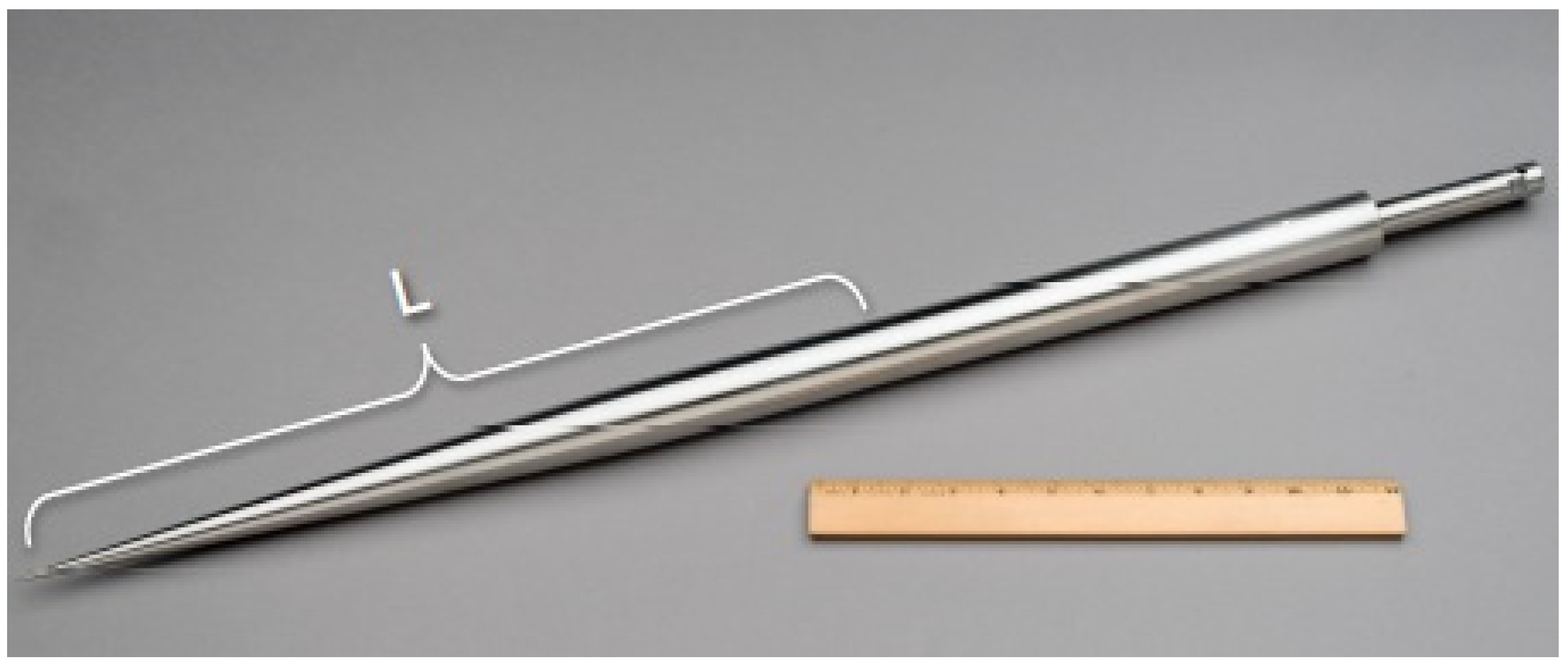
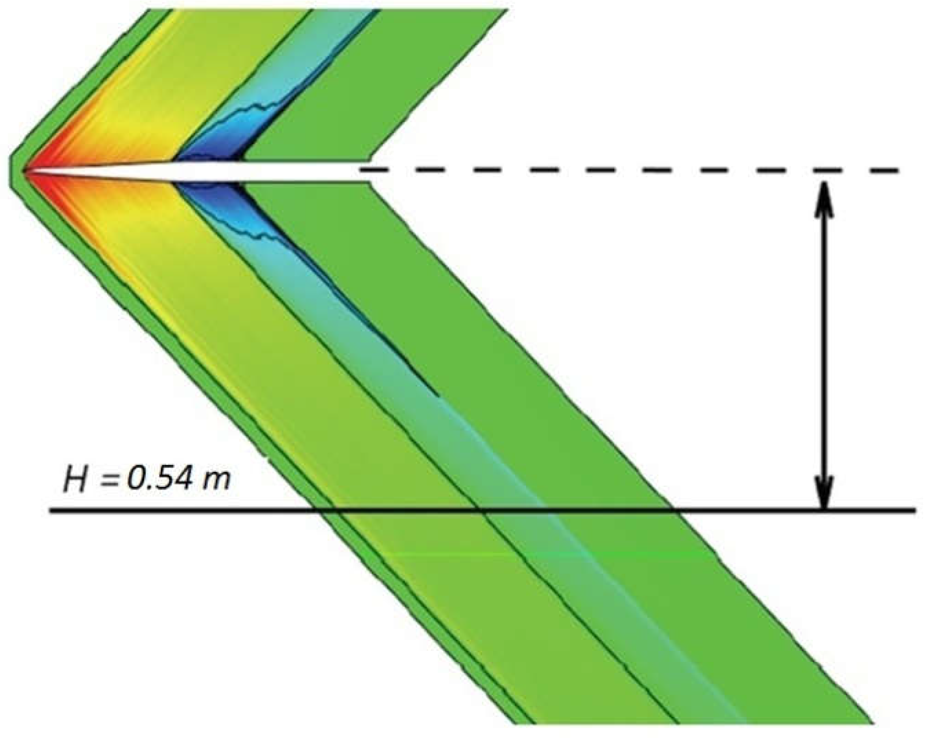
The problem simulates a viscous compressible gas flow around a body with axial symmetry. The body geometry is illustrated in Figure 8. Its length L is 17.667 inches (0.44 m) and its diameter is 1.4 inches (0.035 m) [26].
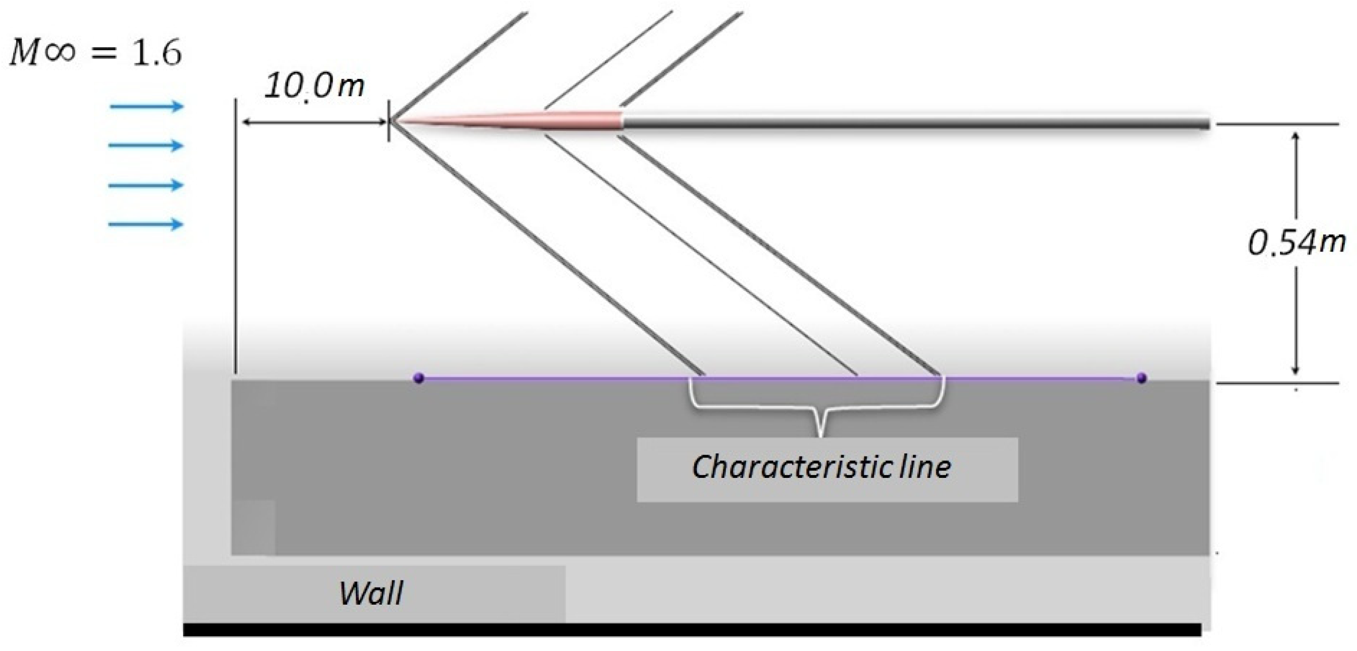
Results of the simulation were compared with the data obtained in the experiment with the mock-up model of object in aerodynamic tube NASA Ames 9 × 7 Supersonic Wind Tunnel. In this experiment, the normalized variation in static pressure along the characteristic line under the object at a distance of 0.54 m was estimated (Figure 9) [26].
According to the experiment, the flow around the body had Reynolds number 6.42 × 10⁶ and the following parameters of the incoming flow: Mach number 1.6, temperature 273 °K, molecular viscosity 1.85 × 10⁻⁵ kg/(m·s), and pressure 1 atm. The flow attacked at a zero angle.
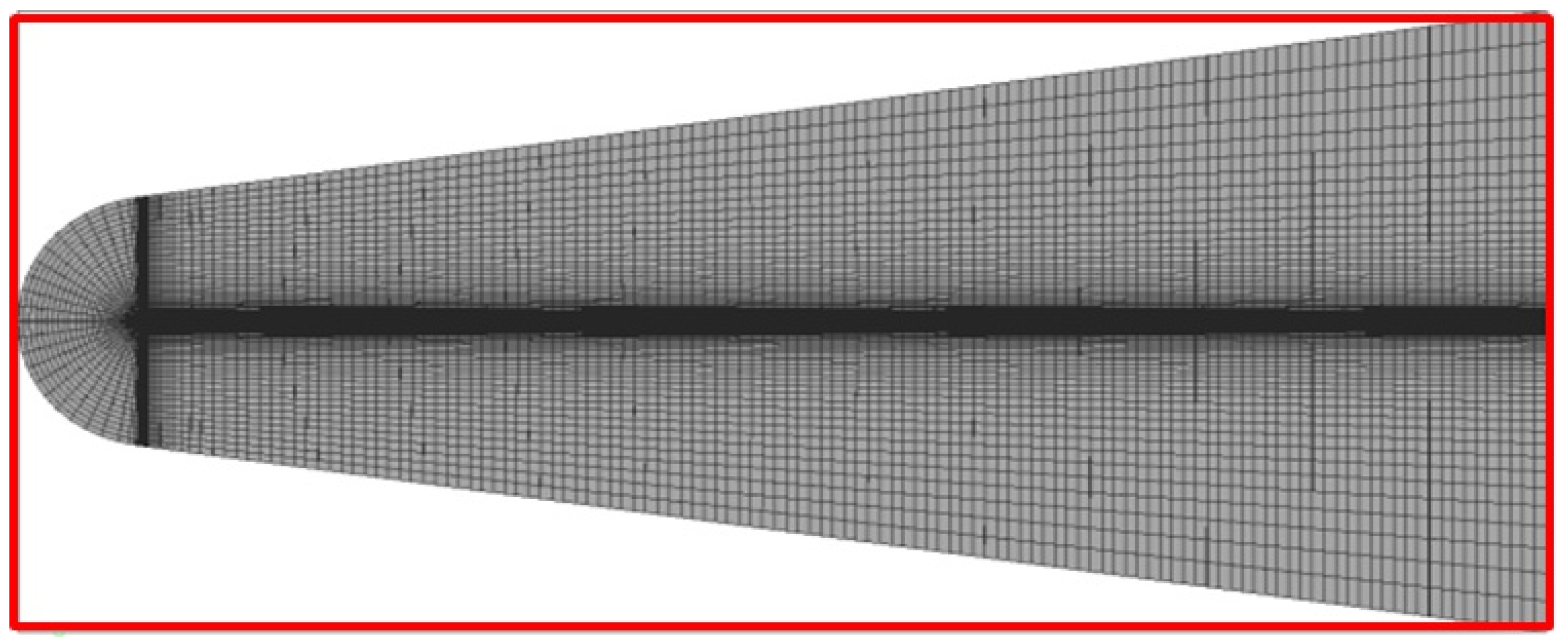
To simulate the given problem with the LOGOS software package, an unstructured computational grid of truncated hexahedrons having 2.5 million cells (Figure 10) was generated, the size of cells was 0.025 m at the grid core and 0.006 m in the refinement block.
The object size in the computational grid corresponds to the model size used in the experiment with flow in aerodynamic tube. There is a prismatic layer—0.005 m long and 15 cells thick—near the object surface. The outer boundary of the computational domain is at a significant distance (10 m) to the object to avoid its effect on the flow simulation results.
To reproduce conditions of the experiment, the “free flow” boundary condition with appropriate parameters was set on the outer boundary of the computational domain. The object surface was a “rigid wall”.
The problem of reaching the steady flow regime was solved. The mathematical model of solution is based on the use of the coupled-type solver, multigrid initialization, an implicit difference scheme, AUSMPW scheme for flows with convection, and Spalart–Allmaras model of turbulence.
The multigrid initialization gave the solution shown in Figure 11. Further, this solution was used for simulations on the basic grid.
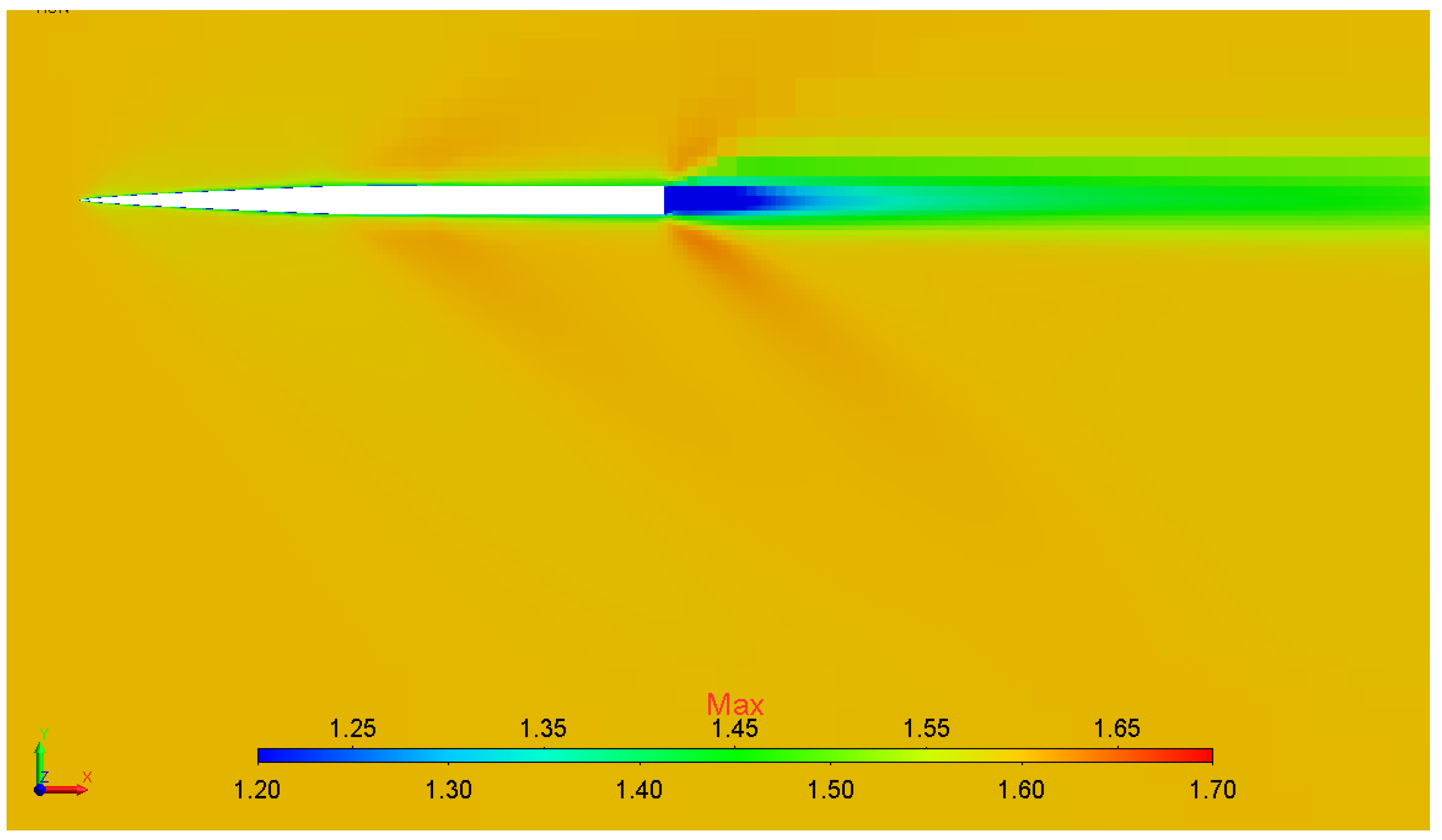
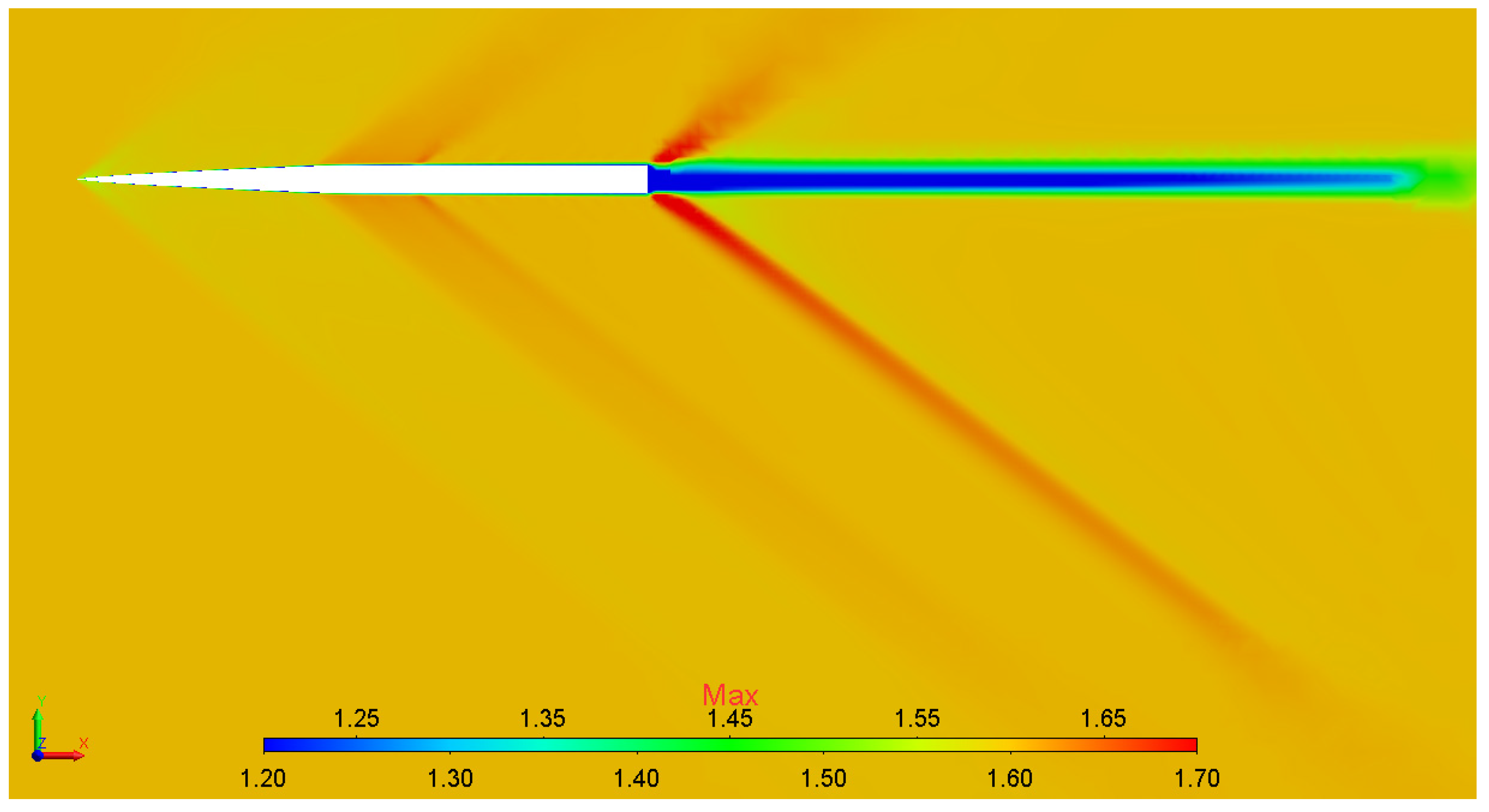
The steady flow problem was solved, the solution obtained is illustrated in Figure 12.
One can see that in the given flow regime a shock wave moving away from the object parts is generated in the flow (a so-called N-wave). With the use of multigrid initialization, 400 iterations were required to achieve the solution convergence, while simulations without multigrid initialization required 550 iterations. As a result, the multigrid initialization provided a 20% speedup with regard to the time spent for it. Figure 13 shows the example plot of drag convergence (Fx).
Table 1 shows the time spent for each calculation session.
Then, the basic grid adaptation was performed using the pressure-based criterion. The solution obtained on the first-level adaptive grid is shown in Figure 14.
Then, simulations on grids of the second and third levels of adaptation were performed. Figure 15 shows the solution obtained and the third-level adaptive grid.
To generate grids of adaptation levels 1, 2, and 3, a typical size of cells in the local refinement region was 0.003 m, 0.0015 m, and 0.0005 m, respectively.
According to results of each numerical test, the normalized static pressure variation along the characteristic line under the object at a distance of 0.65 m was estimated (see scheme in Figure 16) [26].
Normalization was performed with respect to pressure Pref (1 atmosphere) from the outer boundary. Curves for calculated results in comparison with experimental results are given in Figure 17.
Curves in the figure above show that owing to the adaptation algorithm, the solution obtained is more accurate and approaches the experimental data, and this allows the stating of the grid convergence. Owing to the local grid refinement, the shock-wave front region is resolved to a higher accuracy. Adaptation levels following the 3rd level did not give any specification of results.
Characteristic features of grids used in simulations are represented in Table 2.
So, the problem solution results allow making the following conclusions:
  • The method of preliminary multigrid initialization provides up to a 20% increase in the solution convergence rate.
  • The static adaptation algorithm provides efficient automatic generation of a computational model and allows the grid convergence of solution to be gained.

5.2. Simulation of Supersonic Flow around a Model of Aircraft Lockheed Martin 1021 (LM1021)

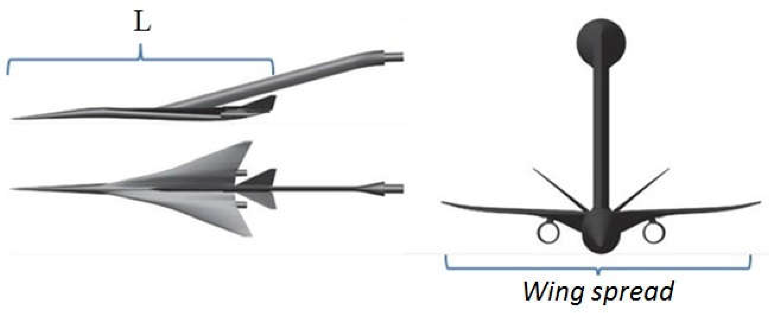
The problem considers a viscous compressible gas flow around a model aircraft Lockheed Martin 1021. The object geometry is illustrated in Figure 18. Its length L equals 22.365 inches (0.569 m) and its wing spread is 8.055 inches (0.205 m).
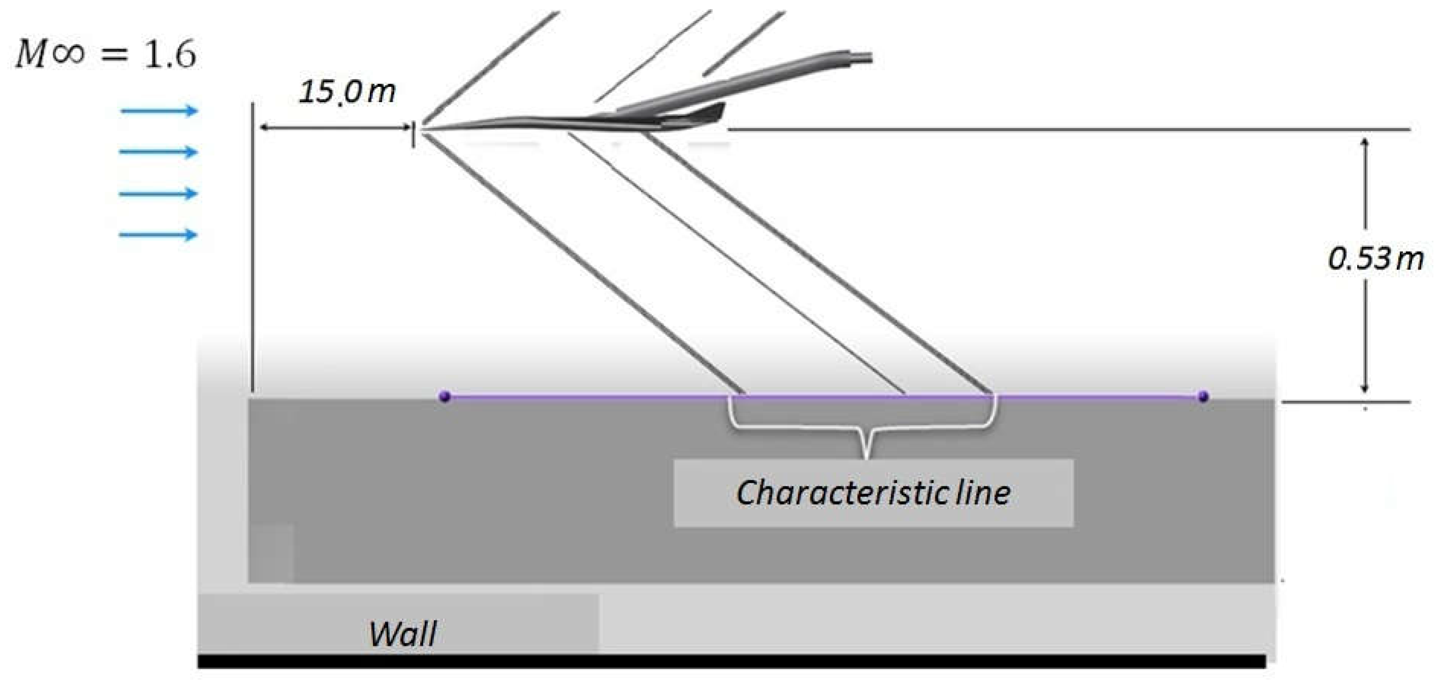
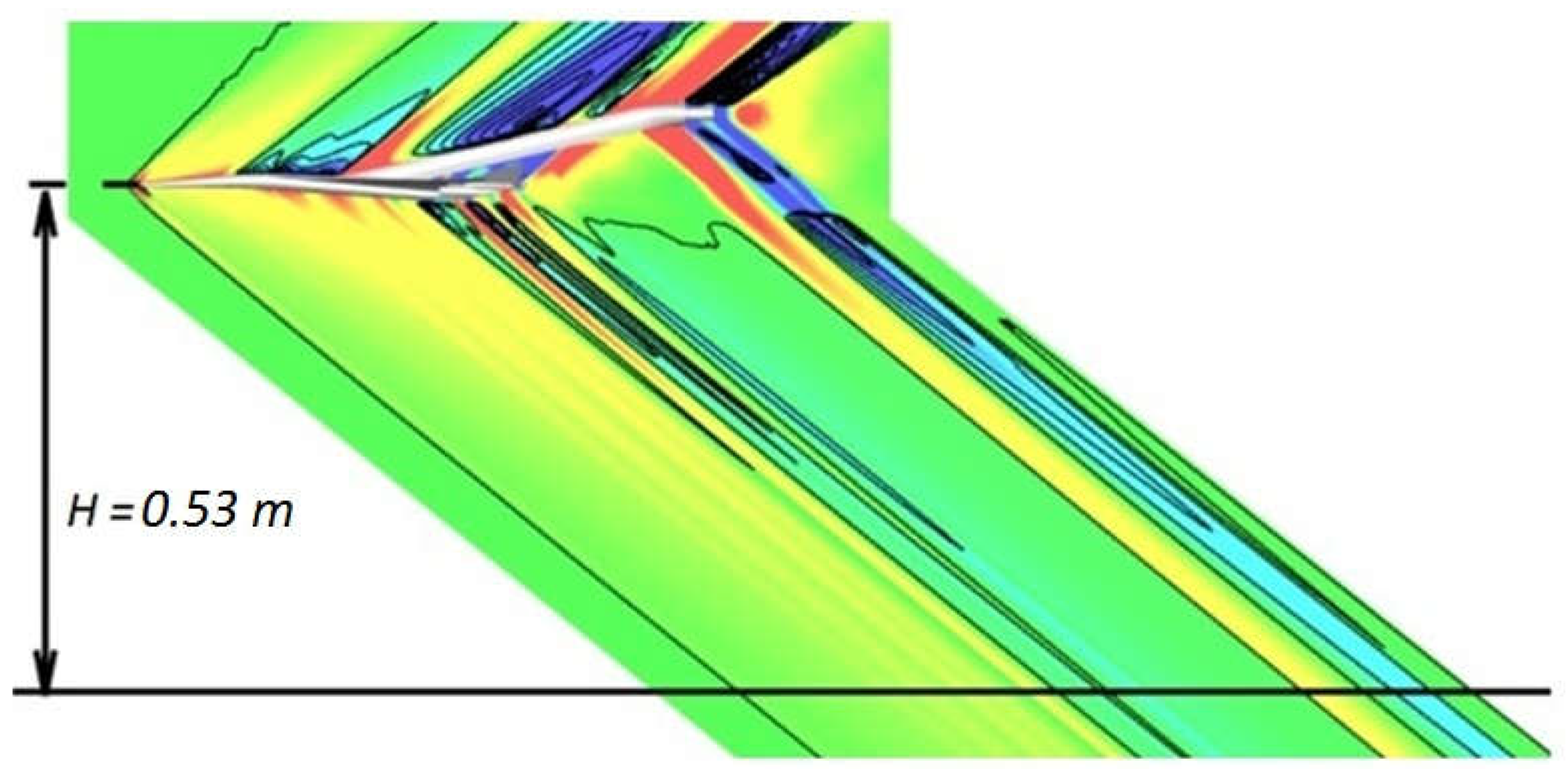
Simulation results were compared with the data obtained in the experiment with a flow around a model object in aerodynamic tube NASA Ames 9 × 7 Supersonic Wind Tunnel. The normalized variation in static pressure along the characteristic line under the object at a distance of 0.53 m [14] was estimated similarly to the previous problem (Figure 19) [26].
According to the experiment, the flow around the body had Reynolds number 8.1 × 10⁶ and the following parameters of the incoming flow: Mach number 1.6, temperature 273 °K, molecular viscosity 1.85 × 10⁻⁵ kg/(m·s), and pressure 1 atm. The flow angle of attack was 2.1°.
To solve this problem with the LOGOS software package, an unstructured computational grid of truncated hexahedrons with 4.5 million cells (Figure 20) was generated, a typical cell size was 0.02 m at the grid core and 0.005 m in the refinement block.
The object size in the computational grid corresponds to the model size used in the experiment with flow in aerodynamic tube. There is a prismatic layer—0.005 m long and 15 cells thick—near the object surface. The outer boundary of the computational domain is at a significant distance (15 m) to the object to avoid its effect on the flow simulation results.
To reproduce conditions of the experiment, the “free flow” boundary condition with appropriate parameters was set on the outer boundary of the computational domain. The object surface was a “rigid wall”.
The problem of reaching the steady flow regime was solved. The mathematical model of the solution is based on the use of the coupled-type solver, multigrid initialization, an implicit difference scheme, AUSMPW scheme for flows with convection, and the Spalart–Allmaras model of turbulence.
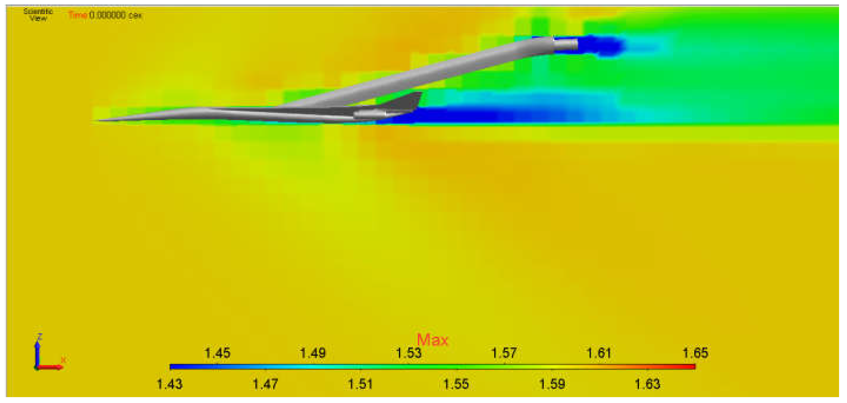
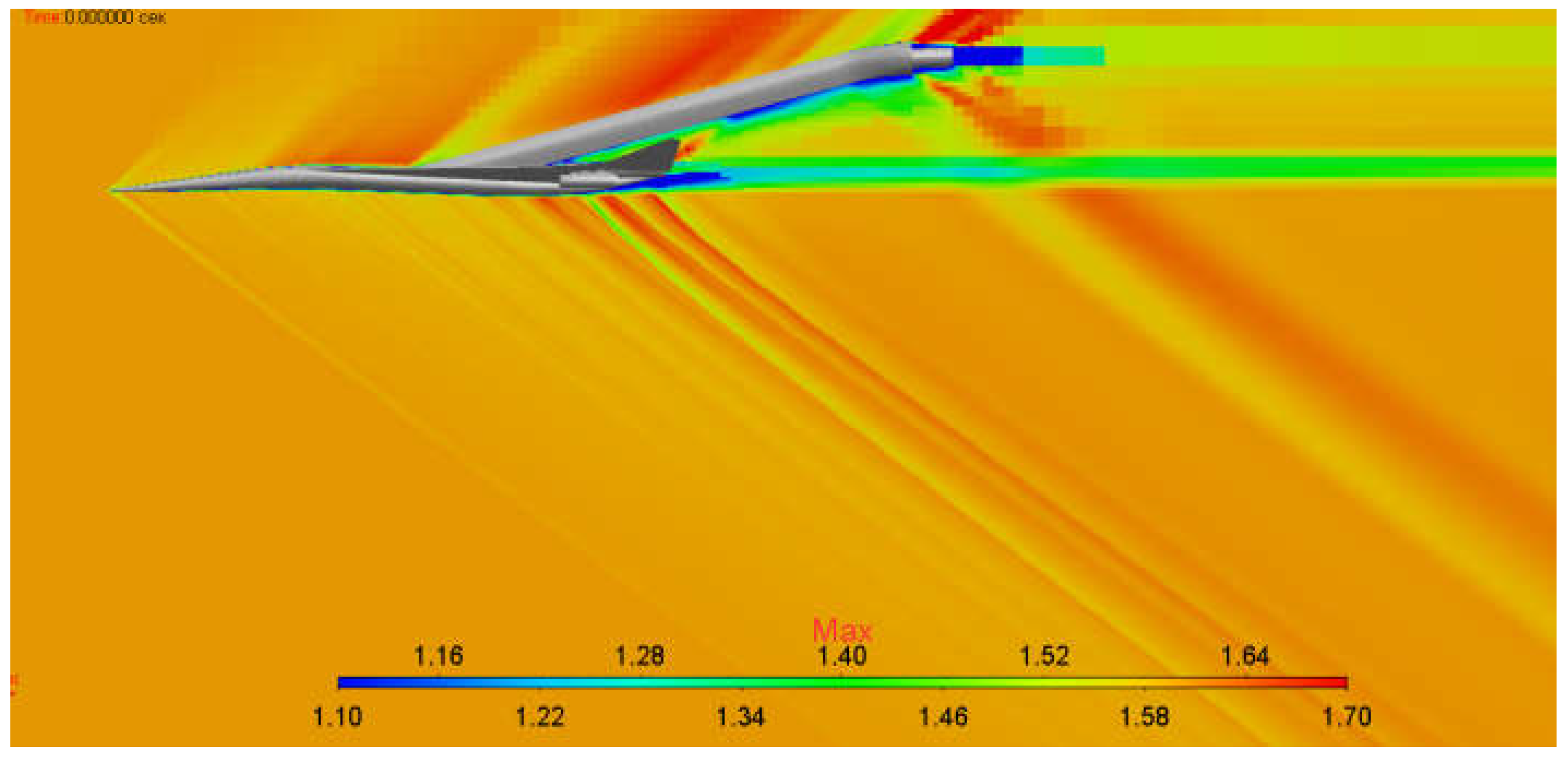
The use of the multigrid initialization gave the solution shown in Figure 21. The solution was further used in simulations on the basic grid.
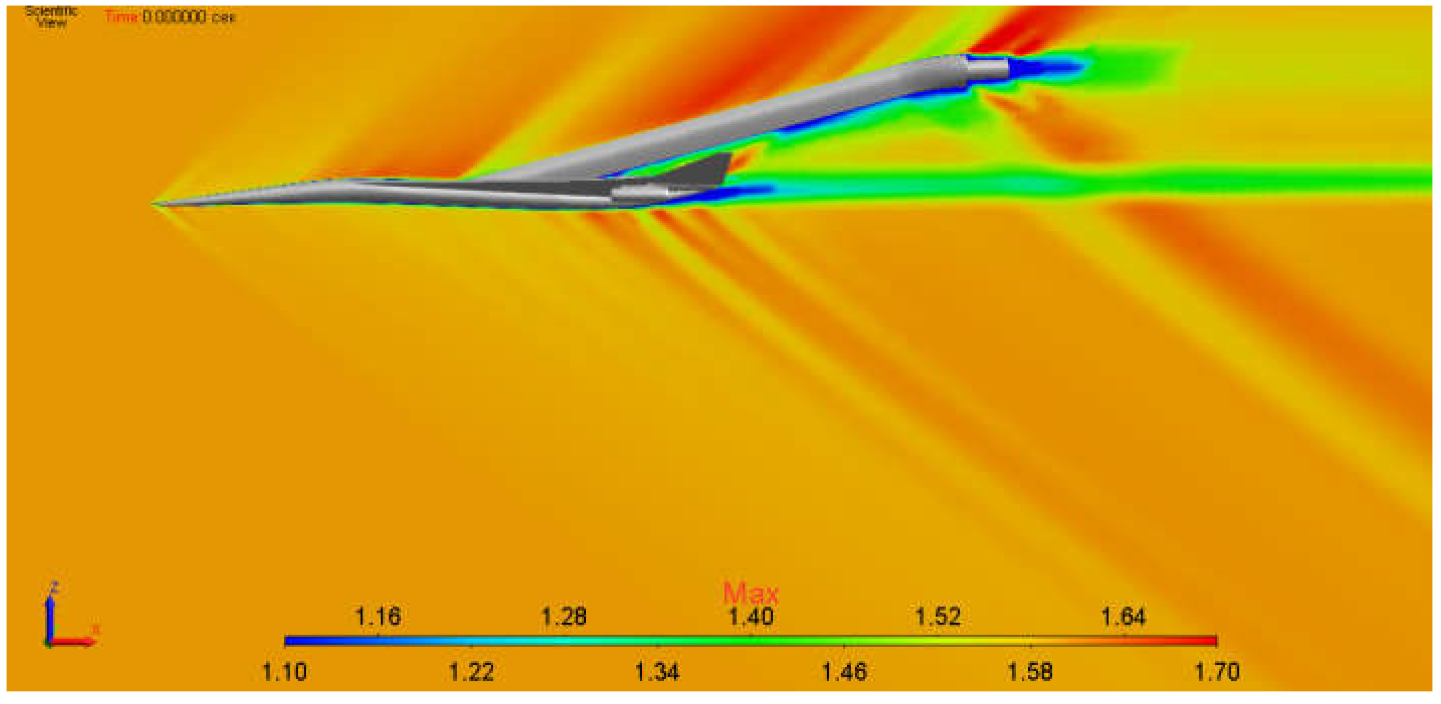
The problem of reaching the steady-state flow regime was solved, the solution shown in Figure 22 below was obtained.
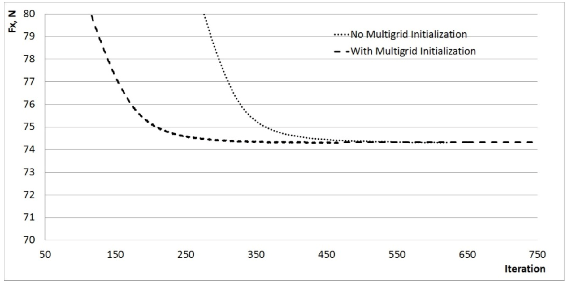
With the multigrid initialization, 355 iterations were required to achieve convergence of solution, while the required number of iterations without the multigrid initialization was 500. As a result, a 20% speedup was provided by the multigrid initialization with regard to the time spent for it. As an example, Figure 23 presents the drag convergence plot (Fx).
Table 3 shows the time spent for each calculation session.
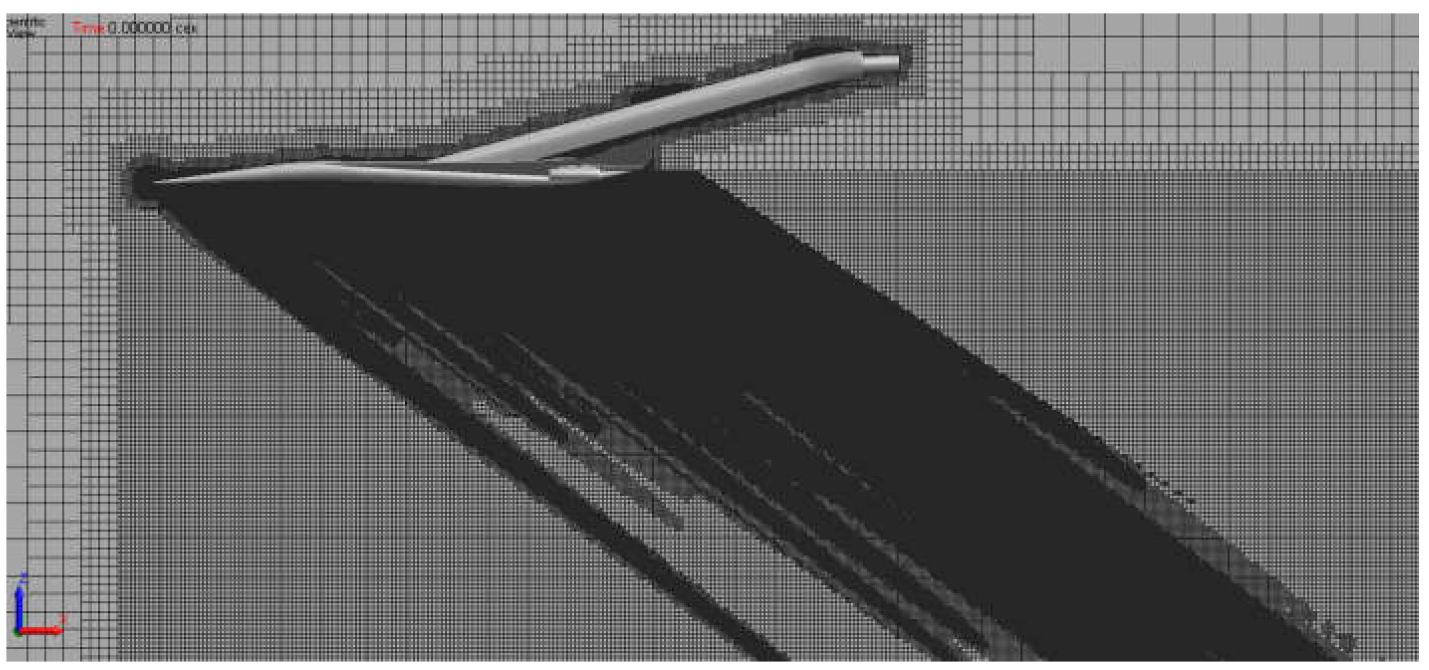
Further, the two-level adaptation of the basic grid was performed using the criterion described above. Typical sizes of cells in adaptation areas were 0.0025 m and 0.001 m for levels 1 and 2, respectively. The solution obtained on the second-level adaptive grid (Figure 24) is shown in Figure 25. Further refinement of the computational model did not lead to changes in the solution and this indicates to the grid convergence of the solution.
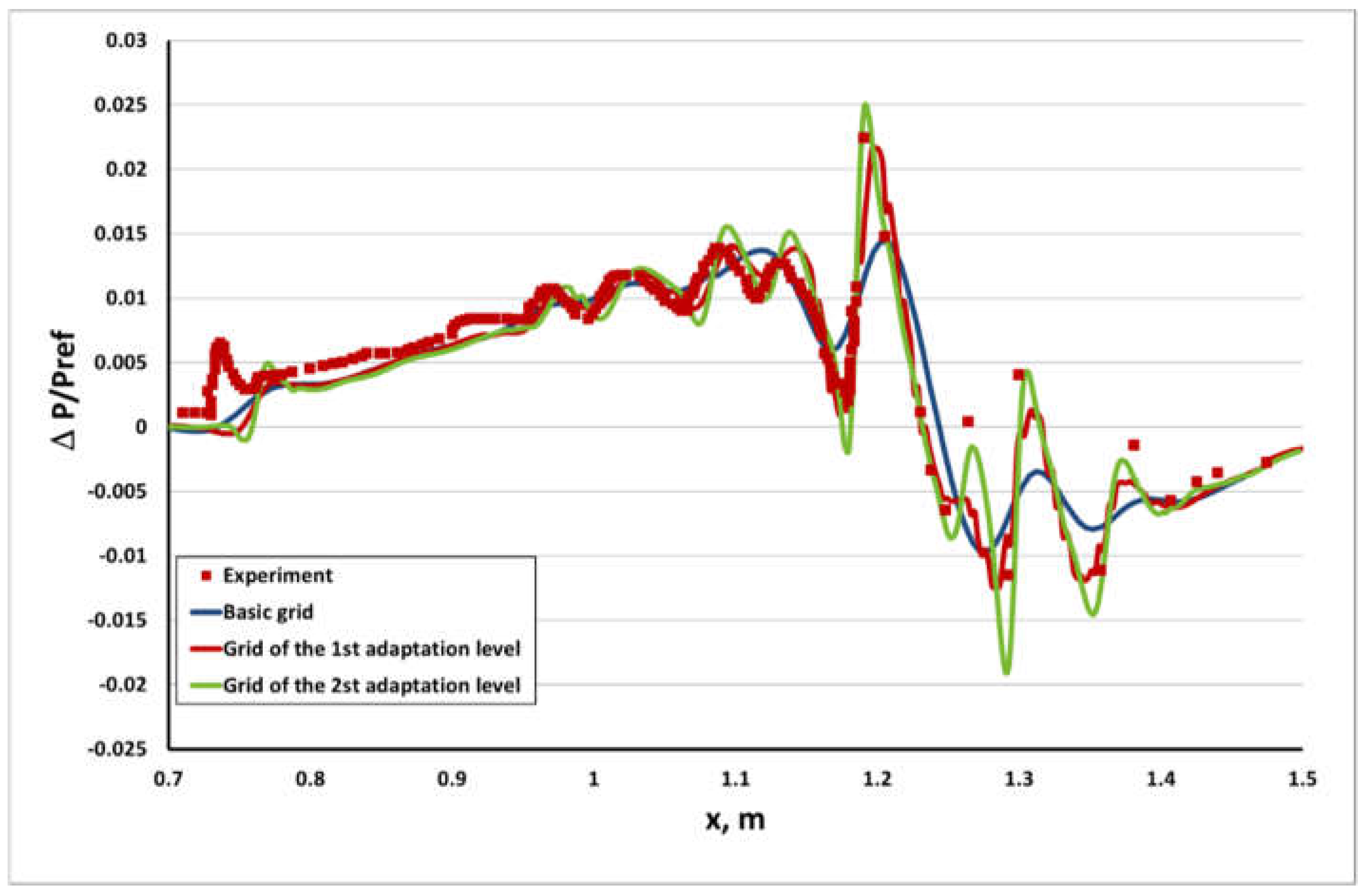
According to results of each numerical test, the normalized variation in static pressure along the line under the object at a distance of 0.53 m was estimated, the result estimation scheme is shown in Figure 26 [26].
Normalization was performed with respect to pressure Pref (1 atmosphere) from the outer boundary. Curves for simulation results are given in Figure 27. The result obtained on the basic grid cannot describe pressure extremum positions in a series of pressure peaks in the afterbody (the range from 1.2 to 1.4 m in Figure 27). This can be explained by an insufficient grid resolution near the shock-wave front. The disturbance propagating from the object dissipates and its strength decreases in cells of the given size. After the adaptation algorithm has been used, the computational grid in the shock-wave region became finer and gave results, which were much closer to the experimental data.
Characteristics of grids used in the numerical simulation are represented in Table 4.
The given problem solution, results allow making the following conclusions:
  • The method of preliminary multigrid initialization allows increasing the solution convergence rate up to almost 20%;
  • The static adaptation algorithm provides efficient generation of a computational model that allows obtaining a more accurate solution owing to the local grid refinement in the shock-wave region and gaining the grid convergence of solution.

6. Conclusions

The paper considers the method of increasing the convergence rate of solution and the method of improving the solution accuracy for the class of supersonic flow problems. The speedup is gained owing to the solution approximation by solving the problem on a series of coarse grids. The solution accuracy improvement is achieved owing to the generation of local refinement blocks by means of the algorithm of adaptively incorporated grids.
The multigrid initialization algorithm is based on solving a problem on a series of coarse grids. The mathematical model is based on the explicit approximation of Navier–Stokes equations and schemes of a lower order of accuracy. The solution obtained on each grid from the series of grids is interpolated to the next one, which is a finer grid, and is used as initialization on it.
The static adaptation algorithm is based on partitioning cells of the original grid to build a local refinement region. The refinement region is selected according to the criterion value, which is calculated with respect to the density, or pressure gradient value.
The application of these two algorithms is demonstrated by the example of two flow problems characterized by the supersonic flow and presence of shock waves in the flow. It was found that with the preliminary multigrid initialization a 20% increase in the solution convergence rate may be gained.

Author Contributions

Conceptualization, A.S.K. and D.Y.S.; data curation, A.V.S.; formal analysis, A.S.K.; investigation, A.S.K., A.V.S. and D.Y.S.; methodology, A.S.K.; software, A.V.S.; supervision, A.S.K.; validation, A.V.S.; visualization, A.V.S.; writing—original draft, A.S.K. and D.Y.S. All authors have read and agreed to the published version of the manuscript.

Funding

The results have been obtained with financial support from the Science & Universities National Project under the Young Scientists Lab Program of the RF Ministry of Education and Science—project identifier No. FSWE-2021-0009 (Research Topic: Development of CFD methods, models and algorithms to simulate liquids and gases in natural and industrial environments under normal and critical conditions on petascale supercomputers) and the Council of the grants of the President of the Russian Federation for the state support of Leading Scientific Schools of the Russian Federation (Grant No. NSH-70.2022.1.5).

Acknowledgments

The work was supported by the Program for Creation and Development of World-Class Scientific Center “Supersonic” in 2020–2025 with financial support of the Russian Ministry of Education and Science (Agreement No. 075-15-2020-924 dated 16 November 2020).

Conflicts of Interest

The authors declare no conflict of interest.

References

  1. Dmitriev, S.M.; Kozelkov, A.S.; Kurkin, A.A.; Legchanov, M.A.; Tarasova, N.V.; Kurulin, V.V.; Efremov, V.R.; Shamin, R. Simulation of turbulent convection at high Rayleigh numbers. In Modeling and Simulation in Engineering; Hindawi Publishing Corporation: London, UK, 2018; Volume 5781602. [Google Scholar]
  2. Kozelkov, A.S.; Krutyakova, O.L.; Kurulin, V.V.; Lashkin, S.V.; Tyatyushkina, E.S. Application of numerical schemes with singling out the boundary layer for the computation of turbulent flows using eddy-resolving approaches on unstructured grids. Comput. Math. Math. Phys. 2017, 57, 1036–1047. [Google Scholar] [CrossRef]
  3. Kozelkov, A.S.; Kurulin, V.V.; Lashkin, S.V.; Shagaliev, R.M.; Yalozo, A.V. Investigation of Supercomputer Capabilities for the Scalable Numerical Simulation of Computational Fluid Dynamics Problems in Industrial Applications. Comput. Math. Math. Phys. 2016, 56, 1506–1516. [Google Scholar] [CrossRef]
  4. Volkov, K.N.; Kozelkov, A.S.; Lashkin, S.V.; Tarasova, N.V.; Yalozo, A.V. A Parallel Implementation of the Algebraic Multigrid Method for Solving Problems in Dynamics of Viscous Incompressible Fluid. Comput. Math. Math. Phys. 2017, 57, 2030–2046. [Google Scholar] [CrossRef]
  5. Kozelkov, A.S. The Numerical Technique for the Landslide Tsunami Simulations Based on Navier-Stokes Equations. J. Appl. Mech. Tech. Phys. 2017, 58, 1192–1210. [Google Scholar] [CrossRef]
  6. Ferziger, J.H.; Peric, M. Computational Methods for Fluid Dynamics; Springer: Cham, Switzerland, 2002; 431p. [Google Scholar]
  7. Wesseling, P.; Oosterlee, C.W. Geometric multigrid with applications to computational of fluid dynamics. J. Comput. Appl. Math. 2001, 128, 311–334. [Google Scholar] [CrossRef]
  8. Kozelkov, A.S.; Kurulin, V.V. Eddy resolving numerical scheme for simulation of turbulent incompressible flows. Comput. Math. Math. Phys. 2015, 55, 1255–1266. [Google Scholar] [CrossRef]
  9. Caraeni, D.; Weiss, J.; Smith, W.; Snyder, D.; Halliday, N.; Clement, J. Continuity Convergence Acceleration of a Density-Based Coupled Algorithm. In Fluid Dynamics and Co-Located Conferences, Proceedings of the 21st AIAA Computational Fluid Dynamics Conference, San Diego, CA, USA, 24–27 June 2013; AIAA: Reston, VA, USA, 2013; pp. 2013–2962. [Google Scholar]
  10. Tsoutsanis, P.; Titarev, V.A.; Drikakis, D. WENO schemes on arbitrary mixed-element unstructured meshes in three space dimensions. J. Comput. Phys. 2010, 230, 1585–1601. [Google Scholar] [CrossRef] [Green Version]
  11. Weizhang, H.; Russell, R.D. Adaptive Moving Mesh Methods; Springer: New York, NY, USA, 2011; 434p. [Google Scholar]
  12. Plewa, T.; Linde, T.; Weirs, V. (Eds.) Adaptive mesh refinement—Theory and applications. In Proceedings of the Chicago Workshop on Adaptive Mesh Refinement Methods, Chicago, IL, USA, 3–5 September 2003; Springer: Cham, Switzerland, 2005. [Google Scholar]
  13. Zegeling, A. Theory and application of adaptive moving grid methods. In Adaptive Computations: Theory and Algorithms; Tang, T., Xu, J., Eds.; Mathematics Monograph Series 6; Science Press: Beijing, China, 2007; pp. 279–332. [Google Scholar]
  14. Arslanbekov, R.R.; Kolobov, V.I.; Frolova, A.A. Kinetic solvers with adaptive mesh in phase space. Phys. Rev. E 2013, 88, 063301. [Google Scholar] [CrossRef] [Green Version]
  15. Baranger, C.; Claudel, J.; Herouard, N.; Mieussens, L. Locally refined discrete velocity grids for stationary rarefied flow simulations. J. Comput. Phys. 2014, 257, 572–593. [Google Scholar] [CrossRef] [Green Version]
  16. Struchkov, A.V.; Kozelkov, A.S.; Volkov, K.; Kurkin, A.A.; Zhuchkov, R.N.; Sarazov, A.V. Numerical simulation of aerodynamic problems based on adaptive mesh refinement method. Acta Astronaut. 2020, 172, 7–15. [Google Scholar] [CrossRef]
  17. Efremov, V.; Kozelkov, A.; Dmitriev, S.; Kurkin, A.; Kurulin, V.; Utkin, D. Technology of 3D Simulation of High-Speed Damping Processes in the Hydraulic Brake Device. In Modeling and Simulation in Engineering; Volkov, K., Ed.; Kingston University: London, UK, 2018. [Google Scholar]
  18. Tyatyushkina, E.S.; Kozelkov, A.S.; Kurkin, A.A.; Pelinovsky, E.N.; Kurulin, V.V.; Plygunova, K.S.; Utkin, D.A. Verification of the LOGOS Software Package for Tsunami Simulations. Geosciences 2020, 10, 385. [Google Scholar] [CrossRef]
  19. Waithe, K. Introduction of First Low Boom Prediction Workshop. In Proceedings of the 51st AIAA Aerospace Sciences Meeting, Grapevine, TX, USA, 7–10 January 2013; AIAA: Reston, VA, USA, 2013; Volume 650. [Google Scholar]
  20. Jasak, H. Error Analysis and Estimation for the Finite Volume Method with Applications to Fluid Flows; Department of Mechanical Engineering Imperial College of Science, Technology and Medicine: London, UK, 1996; 394p. [Google Scholar]
  21. Spalart, P.R.; Allmaras, S.R. A one equation turbulence model for aerodynamic flows. AIAA Pap. 1992, 92–0439. [Google Scholar] [CrossRef]
  22. Shur, M.L.; Strelets, M.K.; Travin, A.K.; Spalart, P.R. Turbulence Modeling in Rotating and Curved Channels: Assessing the Spalart-Shur Correction. AIAAJ 2000, 38, 784–792. [Google Scholar] [CrossRef]
  23. Menter, F.R. Two-equation eddy-viscosity turbulence modeling for engineering applications. AIAA J. 1994, 32, 1598–1605. [Google Scholar] [CrossRef] [Green Version]
  24. Chakravarthy, S.R.; Osher, S. A new class of high-accuracy TVD schemes for hyperbolic conservation laws. AIAA Pap. 1985, 85–0363. [Google Scholar] [CrossRef]
  25. Roe, P.L. Approximate Rieman problem solvers, parameter vectors, and difference schemes. J. Comput. Phys. 1983, 49, 357–393. [Google Scholar]
  26. Cliff, S.E. Computational and Experimental Assessment of Models for the First IAA Sonic Boom Prediction Workshop. In Proceedings of the 52st AIAA Aerospace Sciences Meeting, National Harbor, Maryland, 13–17 January 2014. [Google Scholar]
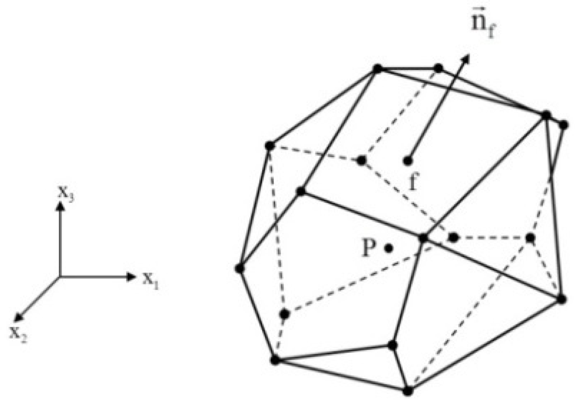
Figure 1. General view of a cell.
Fluids 07 00136 g001
Figure 2. A sizing boxes.
Fluids 07 00136 g002
Figure 3. A uniform grid and one macro cell (closeup).
Fluids 07 00136 g003
Figure 4. Adding new nodes at the center of faces and at the midpoint of edges: (a) a hexahedral cell, (b) a cell in the form of an arbitrary polyhedron.
Fluids 07 00136 g004
Figure 5. Mach number, supersonic flow in channel with a wedge.
Fluids 07 00136 g005
Figure 6. Criterion (5) for density (a) and pressure (b).
Fluids 07 00136 g006
Figure 7. Local refinement of computational grid.
Fluids 07 00136 g007
Figure 8. An axially symmetric body.
Fluids 07 00136 g008
Figure 9. The experiment layout.
Fluids 07 00136 g009
Figure 10. Computational domain. (a) general view, (b) closeup.
Fluids 07 00136 g010
Figure 11. Mach number field, initialization.
Fluids 07 00136 g011
Figure 12. Mach number field, steady-state solution.
Fluids 07 00136 g012
Figure 13. Drag convergence.
Fluids 07 00136 g013
Figure 14. (a) The first-level adaptive grid (b) Mach number field.
Fluids 07 00136 g014
Figure 15. (a) The third-level adaptive grid (b) Mach number field.
Fluids 07 00136 g015
Figure 16. Result estimation scheme.
Fluids 07 00136 g016
Figure 17. Normalized variation of static pressure.
Fluids 07 00136 g017
Figure 18. A model objects.
Fluids 07 00136 g018
Figure 19. The experiment layout (LM1021).
Fluids 07 00136 g019
Figure 20. Computational domain (LM1021), (a) general view, (b) closeup.
Fluids 07 00136 g020
Figure 21. Mach number field, initialization (LM1021).
Fluids 07 00136 g021
Figure 22. Mach number field, steady-state solution (LM1021).
Fluids 07 00136 g022
Figure 23. Drag convergence (LM1021).
Fluids 07 00136 g023
Figure 24. Computational grid, the second adaptation level (LM1021).
Fluids 07 00136 g024
Figure 25. Mach number distribution field, the second adaptation level (LM1021).
Fluids 07 00136 g025
Figure 26. Result estimation scheme (LM1021).
Fluids 07 00136 g026
Figure 27. Normalized variation of static pressure (LM1021).
Fluids 07 00136 g027
Table 1. Calculation time.
Calculation MethodInitializationCalculation Time before ConvergenceTotal Time
With multigrid initialization40 s400 s (1 iteration—1 s)440 s
Without multigrid initialization550 s (1 iteration—1 s)550 s
Table 2. Characteristic features of computational grids.
GridNumber of Cells
Basic grid2.5 million
Grid of the 1st adaptation level4.9 million
Grid of the 2nd adaptation level21.4 million
Grid of the 3rd adaptation level67.5 million
Table 3. Calculation time (LM1021).
Calculation MethodInitializationCalculation Time before ConvergenceTotal Time
With multigrid initialization46.44 s366.36 s (1 iteration—1.032 s)412.8 s
Without multigrid initialization516 s (1 iteration—1.032 s)516 s
Table 4. Characteristics of computational grids (LM1021).
GridNumber of Cells
Basic grid4.5 million
Grid of the 1st adaptation level 10 million
Grid of the 2nd adaptation level52.2 million
Publisher’s Note: MDPI stays neutral with regard to jurisdictional claims in published maps and institutional affiliations.