Article

Special Cases of Using Visualization Technology for Analyzing the Dynamics of Gaseous Environment

Faculty Special Mechanical Engineering, Department High-Precision Airborne Devices, Bauman Moscow State Technical University, 105005 Moscow, Russia
*
Author to whom correspondence should be addressed.
Fluids 2021, 6(8), 290; https://doi.org/10.3390/fluids6080290
Submission received: 30 June 2021 / Revised: 5 August 2021 / Accepted: 11 August 2021 / Published: 18 August 2021

Abstract

:
A new visualization technology is presented, which was used in applied research when observing and modeling the dynamics of the flow of gaseous environments. In the process of developing and improving the technology, a set of experimental results was compiled to study the phenomenon of combustion and detonation of a hydrogen-oxygen mixture, as well as the phenomena of propagation, action, and interaction of shock waves and gas-dynamic structures. On the example of analyzing data on the dynamics of the formation of a vortex ring, the possibilities of verifying the computational model of the implemented physical process are shown. The presented results reflect the level of information content when using technology to carry out tests.

1. Introduction

The experimental–theoretical study of the dynamics and kinetics of reactive rheological media (gas, liquid, mixture) is acquiring new relevance with the development of ways to use these media in innovative pulsed and energy devices. Particular attention is paid to the issues of dynamics of gaseous media in channels and cavities of devices [1,2,3], flow turbulization, temperature and energy thresholds of transitions of media to ignition, detonation, and steady-state propagation velocities. The work [4] can be cited as an example of the study of these issues based on a thorough reconstruction of a virtual picture of gas dynamics processes. The interaction of numerical and experimental visualization for practical use has been considered in many investigations [5,6,7,8,9,10,11]. An example of the technical use of visualization of gas detonation in channels for verification of computational models of processes can be found in the research [12]. The experimentally recorded time sweep of the flame front propagation in a stoichiometric hydrogen–oxygen mixture along the axis of the transparent tube served as the basis. By the slope of the tangent to the trajectory of the combustion front, the velocity of the detonation wave V was determined. This measuring technology is traditional; it provides reliable data on the rate of the process but does not reveal the physical picture in its entirety.
The aim of this work is to demonstrate the possibilities of revealing the phenomenology of physical phenomena from the analysis of the results of experiments on innovative visualization technology [13]. A series of experiments in the field of ballistics is implemented in a given range of initial data. Based on the results of processing the obtained visual data, quantitative predictions are made based on the laws of known theories. This is in contrast to setting up experiments in the scientific method. The purpose of an experiment with a scientific approach is to test a scientific hypothesis. Phenomenology is concerned with the philosophical notion that these predictions describe expected behaviors for phenomena in reality. These models can reveal the phenomenology of the investigated phenomena realized in the investigated range of the initial conditions of the series of experiments.
We chose different variants of fast-flowing gas-dynamic processes for demonstration. Representation of optical recordings in the form of a series of characteristic frames cannot reflect the dynamics, stages, and wave essence of the phenomena. The phenomenology of the phenomenon is revealed only by direct viewing of video files. Below are some typical results from a series of experiments carried out on a research facility when using the method for carrying out ballistic experiments according to the author’s patent RU 2625404, 2017, Bul. No. 20. The physical phenomenon of the formation and dynamics of propagation of a vortex ring has been studied in more detail, acquiring new, modern applications [14]. The phenomenon has a long history of modeling and practical use. In this paper, the phenomenon is considered on the basis and taking into account the results of well-known scientific and practical studies [15,16,17] and using optical imaging technology.

2. Optical Imaging Technology and Equipment

The device and method for carrying out ballistic experiments were developed and applied in laboratory experiments to visualize various ballistic processes. A research launcher was created using the device (RU 2619501, 2017, Bul. No. 14). The active unit of the installation with a guide element and a supply line are shown in Figure 1a.
The active unit of the installation contained a guiding element, the object under investigation (in the presented case, a probe) or a rheological medium, and a control cavity formed by a closed elastic shell. The control cavity was located in the starting zone of the guiding element and filled with a working gas. The control cavity was also connected through a pipeline and shut-off-regulating equipment to a working gas source made in the form of an electrolyzer. Locking and regulating equipment contained a spark gap. The operation of the installation was provided by the control equipment. The mixture was formed as a result of the electrolysis of water and fills the control cavity, made in the form of an elastic destructible shell of the required volume (highlighted in red in Figure 1a). The low optical density of the mixture detonation products made it possible to use a guiding element made of an optically transparent material in the active unit of the launcher. The active unit was located in an armored chamber. The process was illuminated through the windows. Optical registration was performed with a high-speed video camera Phantom v1610.
The operation of the installation and the implementation of the method were based on the conversion of the energy of the working gas—a mixture of oxygen and hydrogen. The installation operation is described in detail, for example, in [4]. The shooting frequency in a series of experiments was from 14,000 to 2,000,000 frames/s. The working gas was a mixture of hydrogen and oxygen in a stoichiometric volume ratio of 2 to 1.
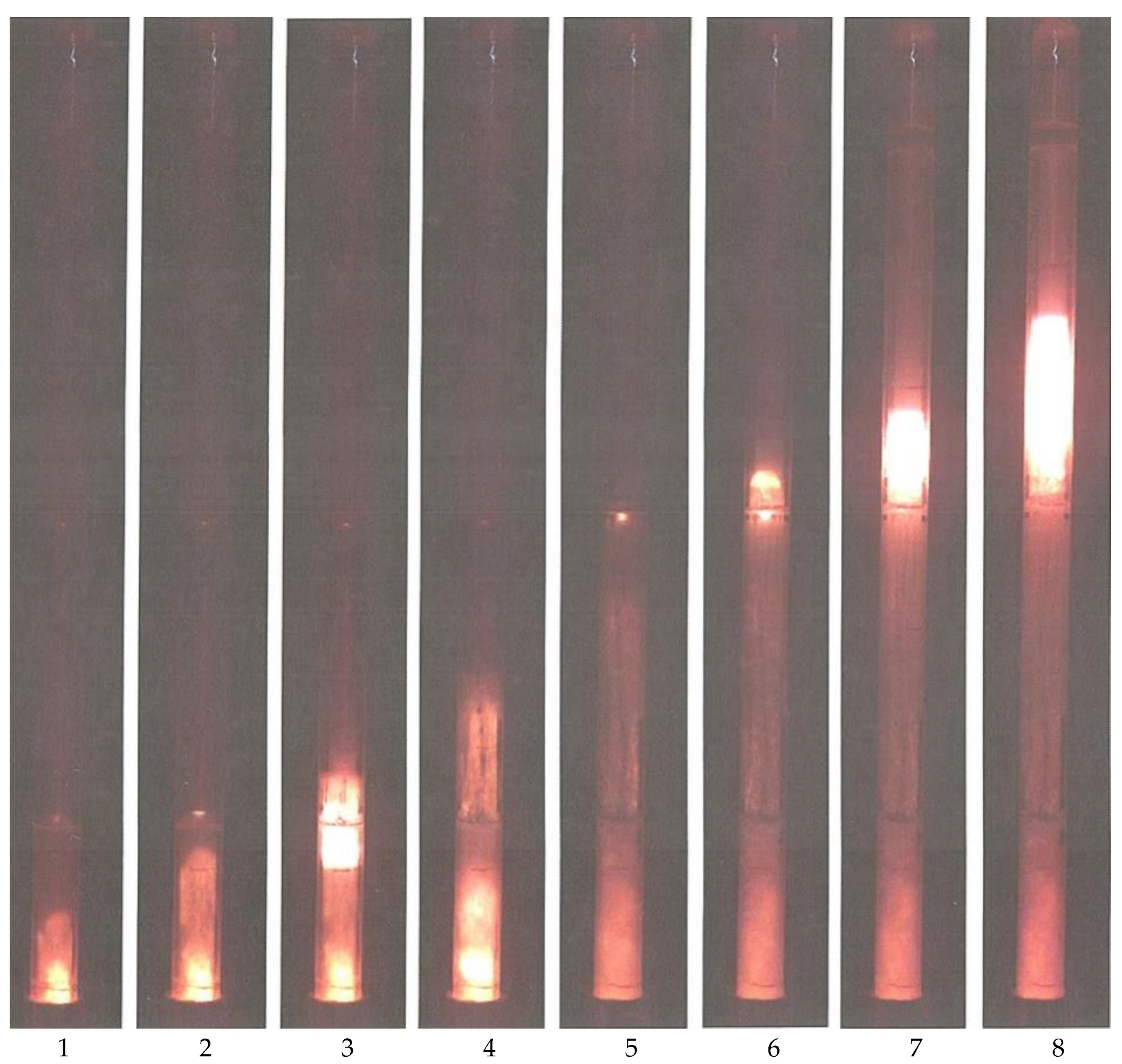
The data in Figure 1b are shown for a guide element 1000 mm long with an outer diameter of 40 mm and an inner diameter of 30 mm. Frames 1 and 2 captured the moment of movement of the detonation wave front up to the bottom of the stationary probe. The middle frame 3 in Figure 1b captured the position of the bottom part at the moment of the fourth reflection of the shock wave from it, while frames 4 and 5 captured the position of the probe in the period of the accelerated movement after repeated impacts.
The realized physical phenomena have an essentially wave nature. For this reason, the phenomenology of phenomena is revealed most clearly when viewing and analyzing the primary file saved in the Cine format. This is one of the possible (Cine, Cine Compressed, Cine RAW, AVI, etc.) saving formats, containing the most complete amount of information about the observed process. The sequence of frames presented in the figures below only reflects the characteristic stages of the studied physical phenomena.
It is possible to evaluate the energetics of the processes by analyzing the data of a series of experiments that implement the processes with different initial parameters. The experiments were carried out in the range of variation of the length L of the guide element from 500 to 1000 mm, the volume U of the control cavity with a working gas from 100 to 400 mL, and the mass m of the probe from 70 to 150 g. The series of photographs presented in this work are given only for illustration of research technology. Quantitative measurements of the kinematic characteristics of the observed process are realized directly when processing a video file saved in the Cine format. The set of the initial parameters of the experiment (L, U, and m) determines the values of the parameters realized in a particular ballistic process. These are the initial velocity V of the probe, the average value of the acceleration dV/dt of the probe, and the muzzle energy E of the probe. As a result of processing the experimental data, the range of variation of these parameters for a guide element with an inner diameter of 30 mm was determined (summarized in Table 1).
The results obtained can be taken into account when preparing experiments with other initial conditions for experiments in a series. The values of the motion parameters of the inertial measuring probe recorded in the experiments were used to verify the calculation models of the processes implemented in the experiments.

3. Results and Discussion

This section presents a set of results of experiments carried out to study the phenomenon of detonation of a hydrogen–oxygen mixture. The set of visualization of particular options under consideration was compiled in the process of developing and improving the technology in the study of the phenomena of propagation, action, and interaction of shock waves and gas-dynamic structures. Video recordings of the processes under consideration were obtained using a high-speed video camera Phantom v1610.
The objectives of this particular version of the study are as follows:
(1)
Study of the mechanisms of transition from combustion to detonation under different initial conditions of the experiment;
(2)
Experimental study of the transfer of detonation from an active charge consisting of a gas mixture enclosed in an elastic shell to a passive charge, also consisting of a gas mixture enclosed in an elastic shell through the air and through a liquid medium (water).

3.1. Propagation of Detonation of the Mixture in Curved Channels

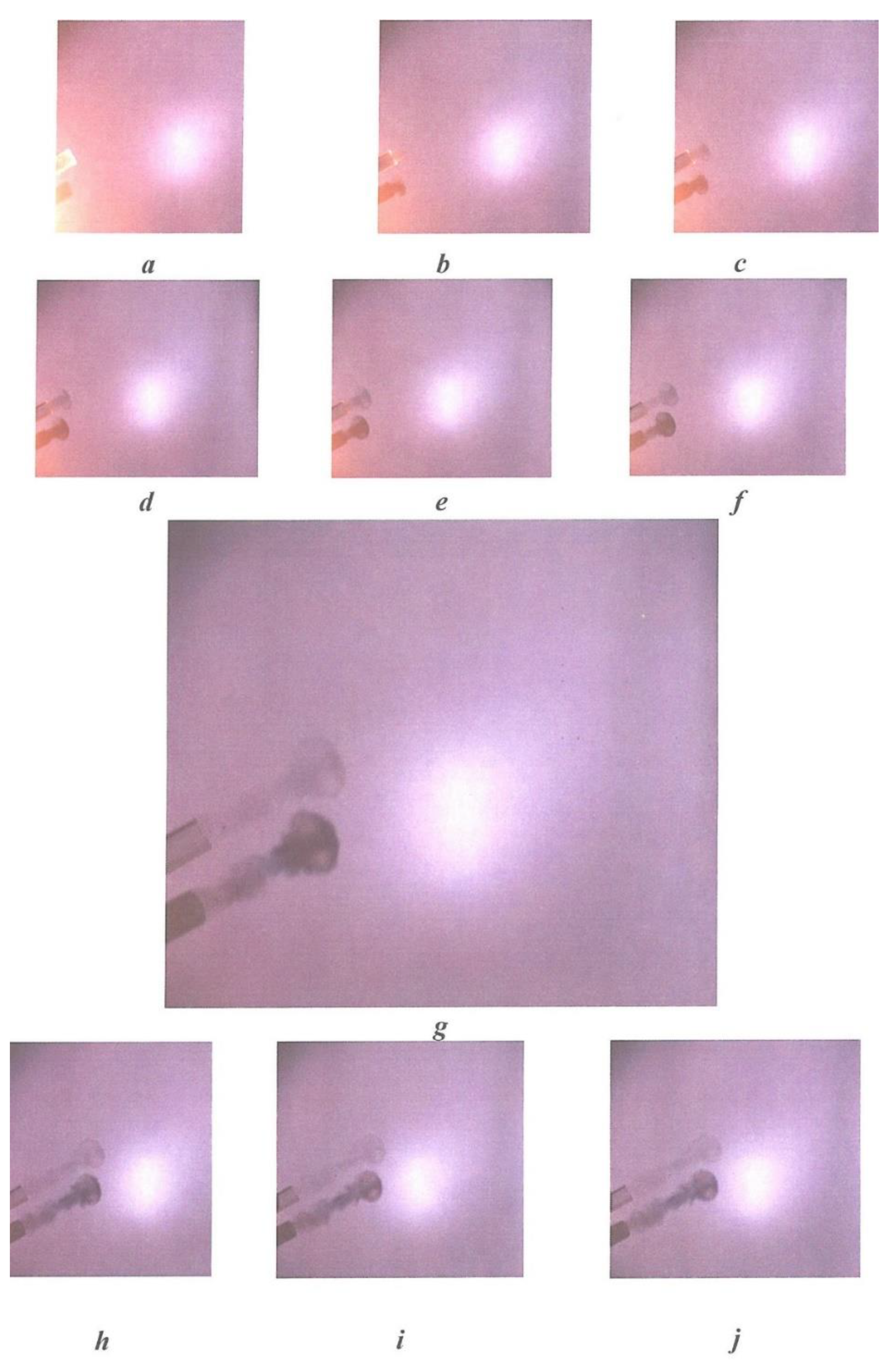
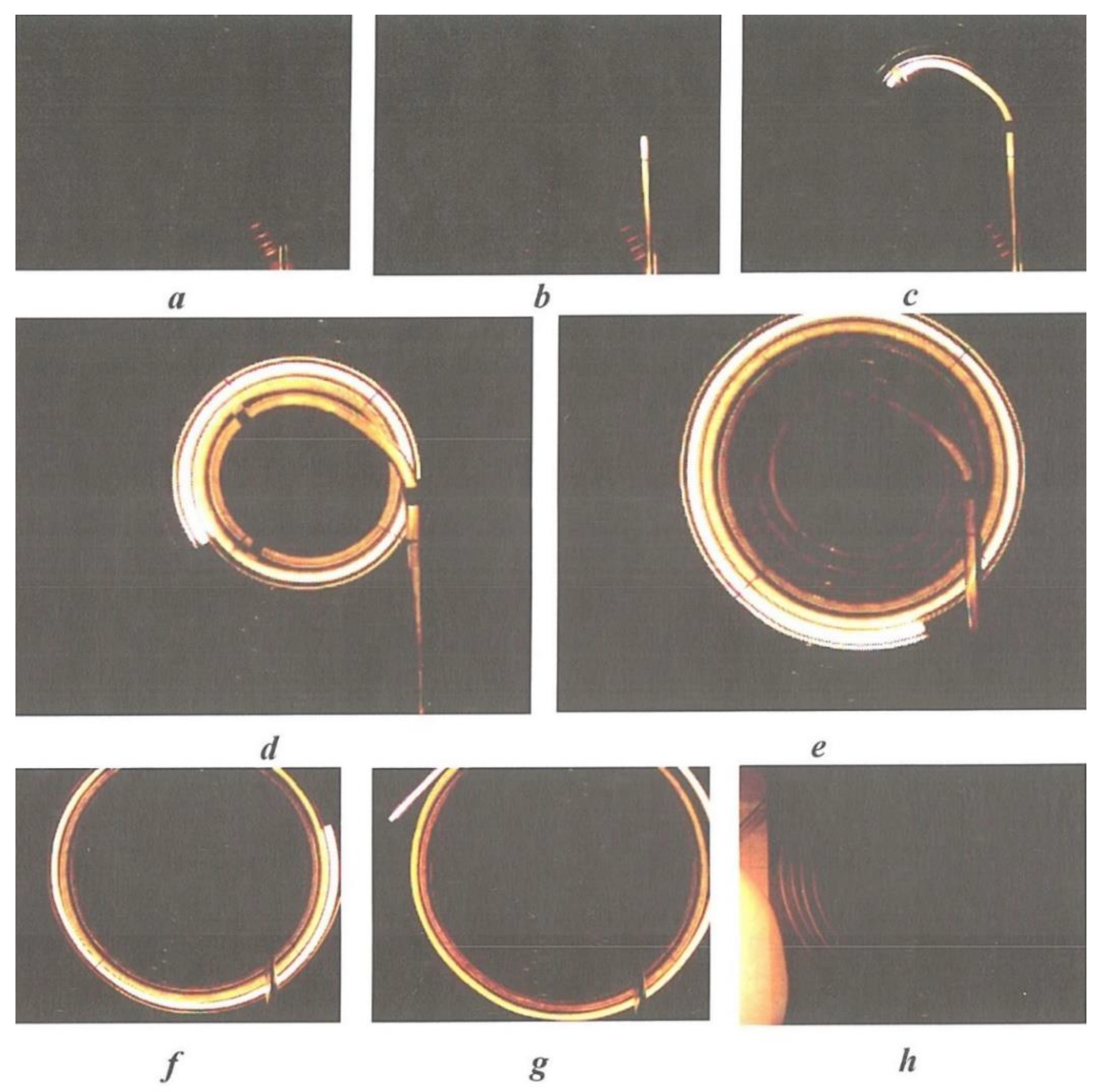
In the series of experiments presented below, the initiation of the active volume of the hydrogen–oxygen mixture was carried out by an electric discharge in a special initiating device. The initiating device, connected to the active charge by a flexible plastic tube, allows using a system of valves to accumulate the gas mixture in the ignition chamber of the high-voltage spark plug, flexible plastic tube, and active volume. At the right time, the mixture was ignited, and the impulse was transmitted to the active volume. The transfer process was investigated in a specially conducted series of experiments with different diameters of the plastic tube: 4, 6, 8, 10, and 12 mm. The tubes were formed into a spiral ring and fixed on a plane. The movement of the detonating pulse through the tubes to the active volume was recorded by a video recorder. Figure 2 shows the results of one of the experiments from the implemented series.
On frame h (Figure 2), an expanding elastic shell of the active volume of the hydrogen–oxygen mixture is visible in the lower-left corner of the frame. Measurements have established a small dependence of the pulse transfer rate on the tube diameter in the investigated range (about 2900 m/s).
The series of experiments carried out demonstrates the reliable transmission of the detonating pulse through the plastic tube to the active volume of the research facility.

3.2. The Transfer of the Detonation of the Mixture through the Air Gap

The active unit is mounted vertically on a special tripod and placed in an armored chamber. The guide element, in this case, is a shock tube 1000 mm long, 40 mm in outer diameter, and 30 mm in inner diameter, made of optically transparent material. The lower part of the guide element is placed in a metal sleeve. The sleeve performs the function of fixing it in the tripod and preventing the shock tube from breaking during the initiation of the active volume of the hydrogen–oxygen mixture. The active volume was an elastic envelope filled with a gas mixture and placed in the lower part of the shock tube. The passive charge was also an elastic shell filled with a gas mixture, placed in the upper part of the shock tube at the required distance from the active charge. According to the experimental conditions, the gap between the charges was either filled with air or filled with a liquid (water). The installation was located in an explosion chamber, and illumination and video recording of the processes with a high-speed video camera Phantom v1610 were carried out through the windows in an armored chamber. The video shooting speed was 84,000 frames/s.
In the experiments, a hydrogen–oxygen mixture was used in a ratio close to stoichiometric. To achieve a constant composition of the gas mixture, the system was purged with a hydrogen–oxygen mixture for at least 5 min.
Figure 3 shows the results of registration of the process with the following initial data: the length of the active volume L = 350 mm; passive volume L = 415 mm; air gap L = 230 mm.
The video recording frames show the following: The combustion front moves (frames 1, 2) along the active volume (up the pipe) at a speed of 850 m/s, then, due to gas compression at the upper boundary, a reflected shock wave is formed (frame 3), which propagates down the pipe at a speed of 1470 m/s and gradually decays. After the destruction of the shell of the active volume (frame 5), a shock wave runs upward through the pipe at a speed of 1340 m/s together with the detonation products of the active charge. The passive volume is initiated in the detonation mode (frames 6–8), the wave propagates at a speed of 2846 m/s.
Figure 4 shows the results of registration of the process, with the following initial data: the length of the active volume is 400 mm; passive, 320 mm; air gap, 237 mm.
The following is observed on the video recording: the initiation of the active volume immediately occurs in the detonation mode, the wave propagates up the shock tube at a speed of 2753 m/s. At the moment of reaching the upper boundary (frame 3), the contact discontinuity decays—the shock wave goes upward (frames 4–6) together with the detonation products (the wave velocity is 1270 m/s), and the reflected shock wave goes downward. Further, detonation is excited in the passive volume and the detonation propagates (frames 7–8) upward to the entire passive volume (the detonation wave velocity is 2925 m/s).
Thus, in the second case, we also observe the transfer of detonation from the active volume to the passive volume through the gap (air layer) by means of adiabatic compression in the shock wave.

3.3. Transfer of the Detonation of the Mixture through the Water Gap

To create a clear boundary between charges and liquid, a technique was developed for supplying gas to a passive volume with the simultaneous use of a drainage tube to evacuate the air in the shock tube.
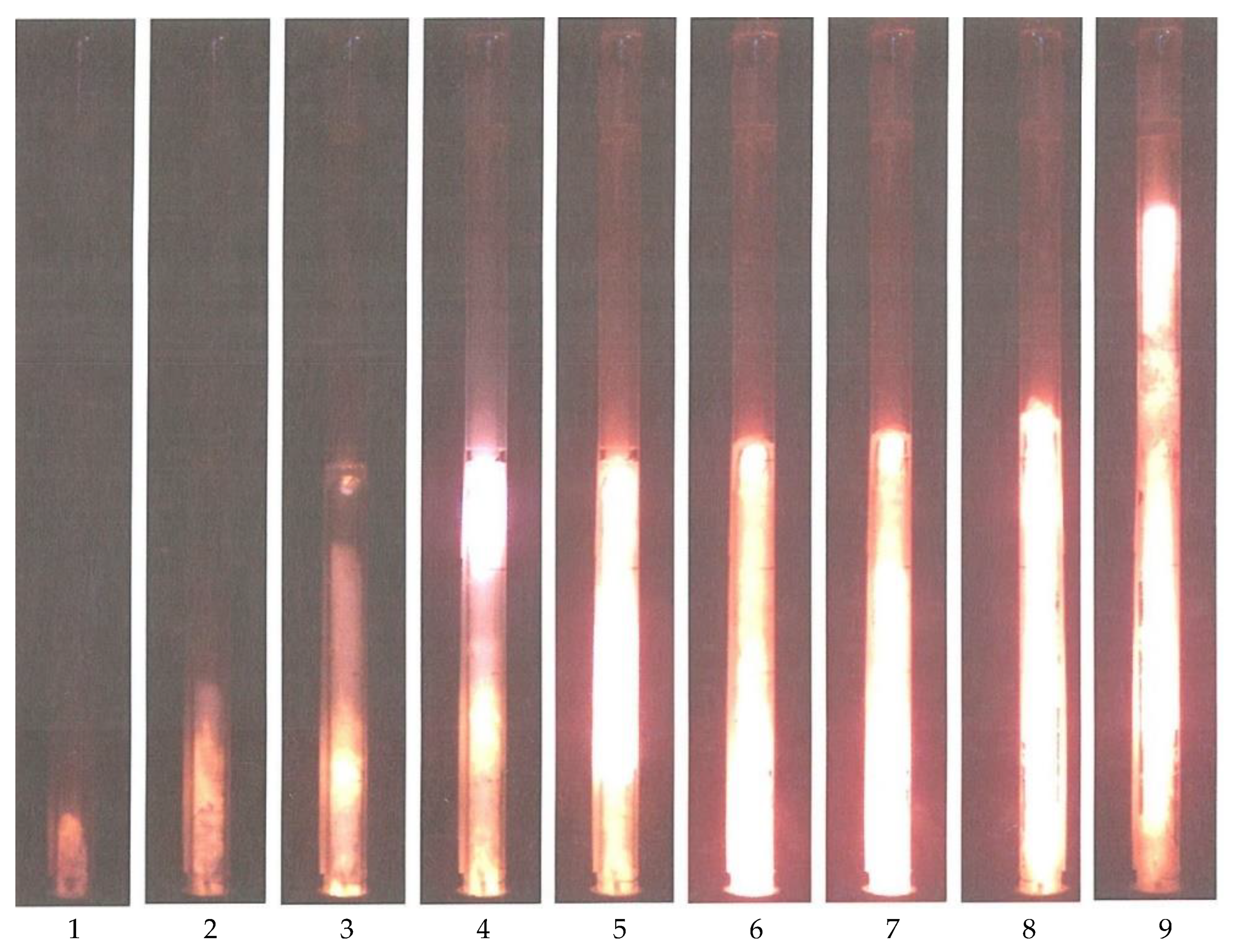
Figure 5 shows the results of registration of the process with the following initial data: the length of the active volume of the mixture is 400 mm; passive, 500 mm; the length of the gap filled with liquid (water) is 10 mm.
On video recording, the following is observed: the initiation of the active volume occurs in the combustion mode, the wave propagates up the tube at a speed of 708 m/s (frames 1–3), due to gas compression, a detonation center is formed at the upper boundary of the active volume (frame 4). Then, the detonation wave propagates down the tube to the entire active volume at a speed of 2216 m/s. At the same time, the elastic shell begins to move along with the water up the pipe (frames 5–7) and, similar to a piston, presses the shell of the passive volume. After the detonation wave in the active charge reaches the lower end, it is reflected, and the reflected shock wave begins to propagate upward with a speed of about 1500 m/s. Next, the passive volume is initiated in the detonation mode (frames 8, 9), and the wave propagates upward through the volume.
The results of a series of experiments with the transfer of detonation through the gap are used to establish the features of the realized physical phenomena and to test the numerical calculations of the investigated processes.

3.4. Detonating Pulse Output to the Water Surface

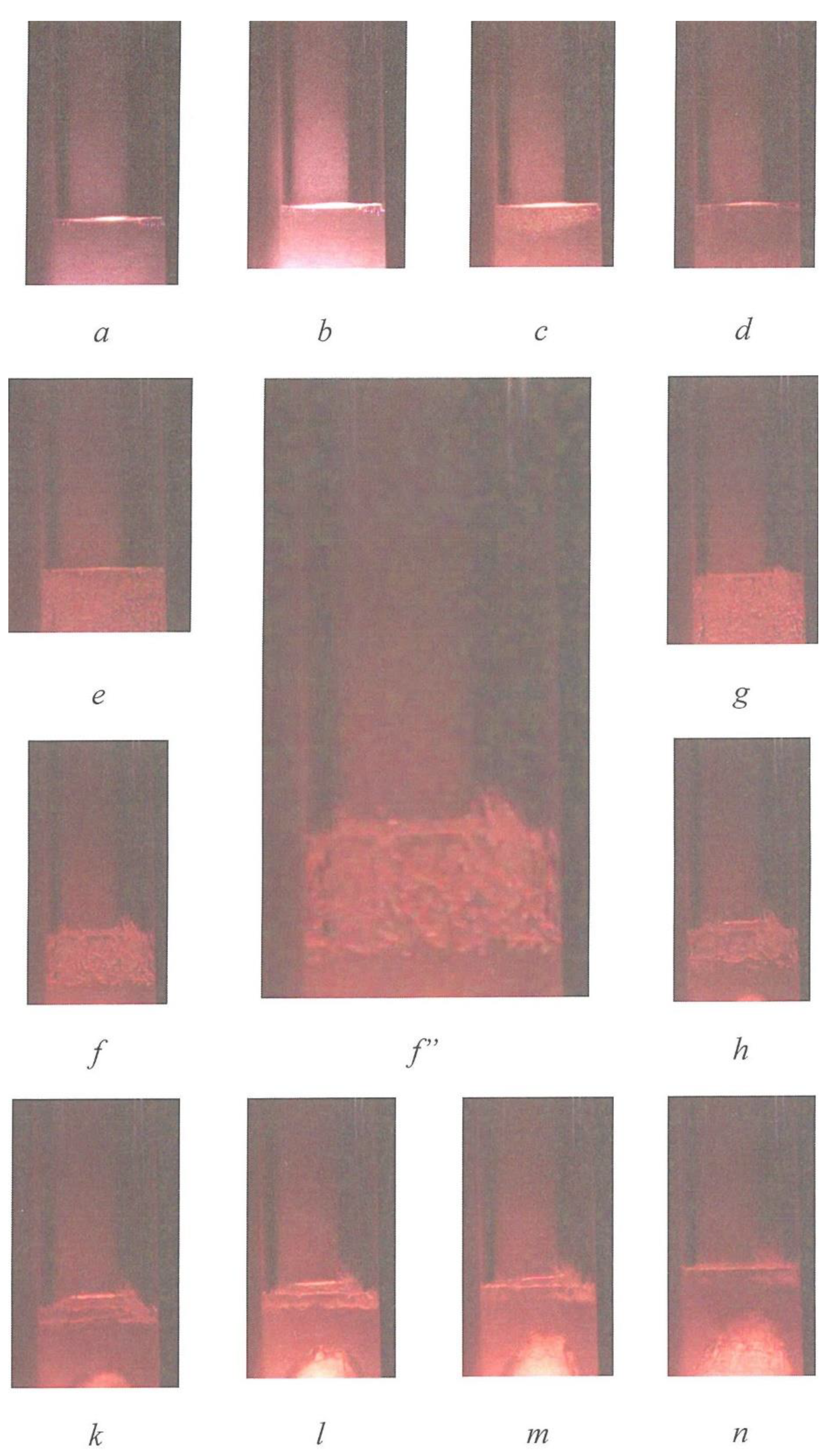
Additionally, in the macro mode, the physical phenomenon of cavitation was investigated when a detonating pulse exits the water surface (Figure 6).
Frame demonstrates in macroscale the moment when the cavitating wavefront reaches the water surface.
Below are some representative results from a series of experiments carried out on a research launcher using the method of accelerating a body in a ballistic experiment.

3.5. Vortex Ring Generation

3.5.1. Phenomena Physical Modeling

To experimentally determine the speed of the vortex ring (VR), a high-speed video recording was performed (the time between frames is 50 ms, the frame exposure is 5 μs) with the Phantom v1610 camera. To visualize the vortex rings, smoke was previously inserted into the volume of the guide element (in this case, also the shock tube) above the active volume of the hydrogen–oxygen mixture. The active volume was initiated, and a detailed physical picture of the formation and propagation of the vortex ring was recorded. The registration variant is shown in Figure 7.
To improve the visual display of the rings, high-intensity illumination and a white substrate were used, so that in the future, not the rings themselves but their shadow displays on the substrate were processed. The processing was performed in the Phantom Camera Control Application program using the built-in tools for measuring the geometric characteristics of the image. The initial moment of time was taken as the moment of the final ring formation, which occurred 0.85 ms after the start of the exit of the colors’ flow from the nozzle of the impact pipe at a distance from the cutoff of ≈1.3 of the nozzle diameter. Next, the distance traveled by the ring from the nozzle section of the shock tube was determined with a step of Δt = 0.25 ms. The average speed of the ring over the traversed interval Δl was determined as the ratio Δlt.
The average coefficient of expansion of the ring α was estimated on the basis of 200 mm and was 0.043. The initial speed of the ring was 100 m/s.

3.5.2. Theoretical Representation of Vortex Ring Formation and Propagation

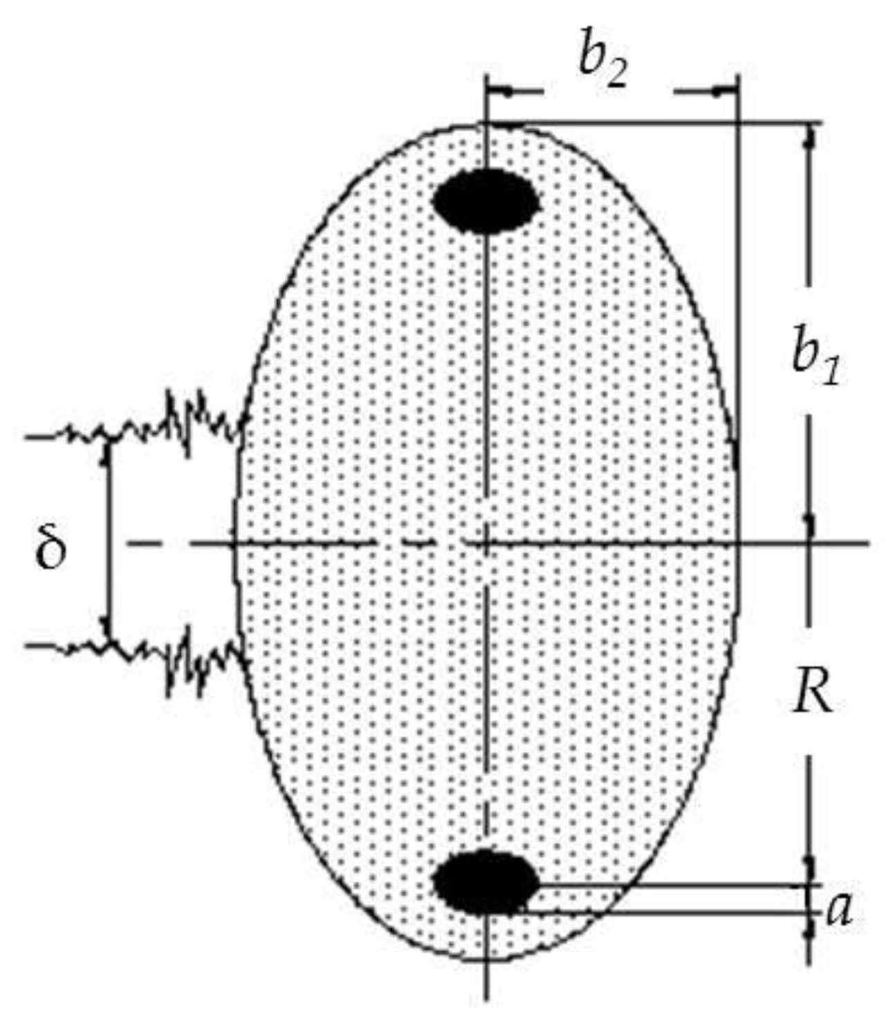
The vortex ring at the main stage of the propagation trajectory is a steady-state aerodynamic structure consisting of a toroidal vortex, inside which almost all the vorticity is concentrated, and the “atmosphere” of the vortex—the region surrounding the core and moving with it. The ring moves in the environment with the preservation of geometric proportions, the main of which is illustrated in Figure 8.
Vortices are formed where the flow velocities change rapidly along the normal values to the fluid flow lines: in these places, large forces of viscous friction arise. In a viscous medium, there can be no sharp boundary between two flows, so there is a transition layer with rapidly changing velocities. The thickness of this layer is less, the lower the viscosity of the medium. Additionally, vortices are often formed when the velocity changes sharply in the direction that leads to the formation of interfaces. Here, too, there is a velocity gradient along the normal to the fluid flow lines and the formation of viscous friction forces that cause small gas particles to rotate first and then larger volumes. When the air is pushed out of the cavity, a boundary layer with significant vorticity is formed on the walls of the cavity nozzle due to viscous adhesion. The formation of the vortex begins when the jet front exits the nozzle into an undisturbed medium. The boundary layer under the action of the velocity field turns into a spiral. The leading edge of the mushroom head of the vortex is the boundary of the liquid that was in the pipe before the start of the jet outflow process. It follows from the results of the experiments that during the main time of the jet outflow, the velocity of the leading edge extension is approximately equal to half of the jet velocity. The jet that feeds the vortex retains its cylindrical shape even after exiting the hole, and only when entering the vortex does its cross section decrease. At high Reynolds numbers, the boundary layer is thin and practically represents a tangential discontinuity, due to the instability of which (Kelvin–Helmholtz instability) the structure of the boundary layer is destroyed. The layers are mixed, which leads to the formation of a vortex core. It is worth noting that the core of the vortex forms only the front part of the boundary layer, and the rest of the latter enters the atmosphere of the vortex, where it spreads more or less evenly by turbulent pulsations and then gradually passes into the vortex path. Figure 9 shows the scheme of vortex ring formation.
It is experimentally defined that the core and the “atmosphere” of the vortex, respectively, account for 7.7% and 92.3% of the total mass of the medium carried by the vortex (at least after its formation), i.e., the mass of the core exceeds the mass of the “atmosphere” by about 12 times [14]. Thus, assuming R/a = k, where k is the experimental coefficient, and the ratio of the volumes of the atmosphere and the core equal to 12 (the density of the vortex medium is determined by the density of the “atmosphere”), we obtain the following estimate: b2 = 41.22(1/k)2b1, i.e., on average, one half-axis of the ellipsoid exceeds the other by 1.5 times.
Let us take a closer look at the VR structure. The maximum velocities vx of each of the sections lie in the plane x = 0 passing through the circular axis of the vortex (Figure 10). In this plane, |vx| > |v0| except for the area close to the circular axis. At infinity, vx tends asymptotically to v0. The maximum values of the vr velocities are localized on the cylinder r = D/2, vanishing at x = 0. At infinity, vr tends to 0.
Next, we provide a justification for the statement about the possibility of transferring various additives (f. e. smoke particles) by the ring [15]. The velocity in the circulation flow, in contrast to the rotational velocity of a solid, decreases along the hyperbola with increasing radius. The pressure, on the contrary, according to the Bernoulli equation decreases from the periphery to the center.
On the axis of the vortex, the potential flow is disturbed: the vortex core of the circulation flow, having a small diameter, rotates already as a solid body and the Bernoulli equation is not applicable here. In the core, the linear velocity increases from the center to the periphery in proportion to the distance to the boundary between the vortex core and the atmosphere. The position of this boundary depends on the angular velocity of the core.
Using the equation of gas element equilibrium in a steady circulation flow around a single vortex and bearing in mind that in the core v = ωr, where ω is the vorticity (s−1), we obtain the following:
Δ p = ρ v 2 r Δ r = ρ ω 2 r Δ r .
The sign of Δp coincides with the sign of Δr, therefore, inside the vortex core, the pressure continues to decrease from the periphery to the center (although the speed also decreases toward the center). Thus, a strong suction occurs in the core, due to which outer particles are drawn (sucked) into the core.
The parameters of the vortex torus can be described using the model of a cylindrical vortex with a finite core of a circular cross section of radius a, in which the vorticity ω is constant—the Rankin vortex [16] (Figure 11). Outside the core, the current is assumed to be vortex-free. Such a vortex can be approximated by a continuous distribution of rectilinear vortex filaments in the core. Then, the cross-sectional element of the core dS gives a contribution to the circulation dΓ equal, according to Stokes theorem, to dΓ = ωdS. The circulation along any contour that once covers the entire core of the vortex is Γ = ωπa2 = const.
If we take into account the axial symmetry of the problem, i.e., the presence of only the circumferential component of the velocity vr = vr(r), then from the Stokes theorem for a circle of radius r > 0 we have 2πrvr = ωπa2, from where, taking into account the expression for circulation, we find an expression for the velocity in the region of the vortex-free (potential) flow.
v r = a 2 ω 2 r = Γ 2 π r , r > a .
Inside the core, we similarly obtain 2πrvr = πr2ω or
v r = Γ r 2 π a 2 , r < a .
The average velocity in the VR core can be estimated as the ratio of the linear velocity at the boundary of the core to the radius of the core. From experimental data [8], at the Reynolds number Re = 7.5 × 10⁴, the angular velocity of rotation in the core reaches 35,000 rpm. The forward speed of the ring is 11 m/s. In experiments conducted with the help of a shock tube, rings with a translational velocity of more than 100 m/s were obtained (in particular, at the speed of the outgoing jet of 198 m/s and the radius of the generator nozzle of 25 mm, a ring with a radius of 33 mm moving at a speed of 99 m/s was obtained).
The radial distribution of static pressure is characterized by its sharp decrease in the vortex core. To calculate the pressure profile, we apply the Euler equation, which in polar coordinates, taking into account the axial symmetry, will take the form ρ v r 2 r = d p d r , from where p = p + r v r 2 r d r , where ρ is the density of the medium; p the pressure at infinity. Substituting the velocity profiles in the expression for pressure, we find the pressure distribution
p = p ρ ω 2 a 4 8 r 2 , r > a ,
p = p ρ ω 2 a 2 4 + ρ ω 2 r 2 8 , r < a
The minimum pressure is achieved on the axis of the vortex as follows:
p min = p ρ ω 2 a 2 4 = p ρ Γ 2 4 π 2 a 2 .
At the core boundary,
p p min = p min p 2 .
For an infinitely thin vortex thread of intensity Γ, the pressure on the axis tends to (−∞), as can be seen with a tending to 0.
To determine the initial geometric parameters of the vortex ring, we can write a closed system of equations as follows:
R 0 = k 1 D n / 2 a 0 = R 0 / k b 10 = R 0 / 0.9 b 02 = 41.22 ( 1 / k 2 ) b 10
where Dn is the exit diameter of the nozzle, R0 is the initial radius of the ring, a0 is the initial radius of the ring core; b1 and b2 are the dimensions of the sides of the “atmosphere” of the vortex (taken as an ellipsoid), k1 = 1.1…1.3 experimental coefficient that determines the expansion of the ring at the exit from the generator nozzle (when the ring is formed inside the generator, k1 can be taken equal to 1), and k is the coefficient.
Since the vortex is a stable structure, we assume that its geometric parameters change proportionally on the trajectory.
To determine the kinematic characteristics of a vortex ring, we consider a physical model of its motion in the environment.
For further discussion, we will take the following notation: U is the forward velocity of the vortex ring; u is the rate of expansion of the vortex ring along the y axis; vel is the velocity modulus of the vortex element; ρ1 is the density of the medium outside the ring (since the motion of the ring at the earth’s surface is considered, we can take ρ1 = 1.29 kg/m3—the density of air under normal conditions); ρ is the density of the medium inside the ring (determined by the density of the “atmosphere”); Γ is the velocity circulation; S is the area of the midsection of the vortex; M is the mass of gas in the vorticity region; M1 is the mass of gas in the “atmosphere”.
In the framework of the physical model of the process used, based on [17], we assume the following assumptions:
-
The gas heated to a certain temperature and located in the generator chamber exits the nozzle in a uniform laminar flow, the core of the vortex is completely formed from this gas, and the “atmosphere” of the vortex is formed from the surrounding cold air;
-
During the movement of the vortex, there is a constant mass exchange of the gas forming the “atmosphere” of the vortex with the external environment due to turbulent mixing;
-
The air in the core of the vortex does not flow out; therefore, as the size of the core increases, colder air from the “atmosphere” flows into it, which leads to a gradual cooling of the core.
When the ring moves, the following three forces act on it:
(3)
The power of Zhukovsky
F Z h = ρ 1 v e l Γ R d φ ,
The Zhukovsky force acts perpendicular to the gas element motion direction; its vertical component stretches the ring, and the horizontal component slows down its movement (for a circular vortex ring FZh = 2πρ1ΓvelR);
(4)
Hydrodynamic drag force
F g d = C x ρ 1 U 2 S / 2 ,
where Cx is the coefficient of resistance of the vortex, and S is the area of its midsection. The force due to the pressure difference in front of and behind the ring and the viscous friction on the surface of the body, determined by the disruption of the flow from the back side (friction at the boundary, as already noted, is small) and directed opposite to the forward velocity of the ring;
(5)
The Archimedean force, which arises from the difference in the densities of the air inside the ring and in the atmosphere,
F A = ( ρ ρ 1 ) g V r o t ,
where Vrot is the volume of the “atmosphere” of the vortex.
Thus, it is possible to obtain the equations of ring motion in projections on orthogonal coordinate axes as follows:
d d t [ U ( M + M 1 ) ] = 2 π ρ 1 Γ R u ρ 1 U v e l 2 C x S d d t [ u ( M + M 1 ) ] = 2 π ρ 1 Γ R U ρ 1 u v e l 2 C x S + g V r o t ( ρ 1 ρ )
Analyzing the large array of experimental data obtained, we can conclude that the most acceptable form of estimating the change in the radius of the vortex ring on the trajectory is the formula
R ( t ) = R 0 + α L ( t )
where α = R/L is the expansion coefficient determined from the experiment (for estimated calculations, we can take α ≈ 0.01). Thus, the rate of expansion of the ring is constant over the entire trajectory of its motion, and in System (2), we can take u = αU, and then consider only the first equation of the system, in which the approximation Uvel will be valid.
When decomposing the left part of the equation, we can distinguish the mass transfer factor v d m / d t , where m = 1.08M1 is the total mass of the vortex ring, taken from the condition M1/M = 12. Let us assume that mass exchange with the environment occurs only in the “atmosphere,” and in the core of the ring, the environment remains unchanged during movement. Estimates for the mass transfer factor dm/dt are semiempirical. Considering the motion of the vortex ring in the form of an ellipse of rotation with a major semiaxis b1 = R/0.9 and with a mass m = 1.08M1 = 1.08πRcgSell, where Rcg is the coordinate of the center of gravity of the half of the ellipse, and Sell = πb1b2, and taking the postulate of preserving the shape of the vortex, as well as the linear dependence of the increasing radius on the distance traveled, we obtain the ratio
d m d t = 781.5 k 2 ρ α R 2 U
Thus, the mass of the turbulent vortex ring increases linearly in accordance with the distance traveled by the vortex, due to the involvement of media from the environment in the vortex motion. As a result of this process, the kinetic energy is lost, and the vortex is decelerated.
The relationship between the density of the gas forming the vortex and the temperature can be determined using the Clapeyron–Mendeleev equation.
ρ T = i n v .
The temperature of the vortex ring at the current time can be defined as
T = V 0 V ( T 0 T i n v ) + T i n v
where V0 is the initial volume of the vortex ring, which can be assumed to be equal to the volume of the generator chamber; T0 is the initial temperature of the gas in the ring; Tinv is the ambient temperature.
The circulation of the medium in the vortex ring can be determined by the Burgers formula
Γ = 1.39 2 π a U
Thus, from the first equation of the System (1), we finally obtain the differential equation
d U d t = U 2 m ( A + B + C )
where A = 70.8 α k R 2 —coefficient of geometric dimensions of the ring; B = ρ 1 C x S 2 —coefficient of the geometric shape of the ring; C = 781.5 k 2 ρ α R 2 —mass transfer coefficient.
The visualization technique considered in this paper may be used to verify the developed model of the motion of the vortex ring, which is the subject of a separate study. Here, for example, we will present a specific result of comparing theoretical representations with experimental results.
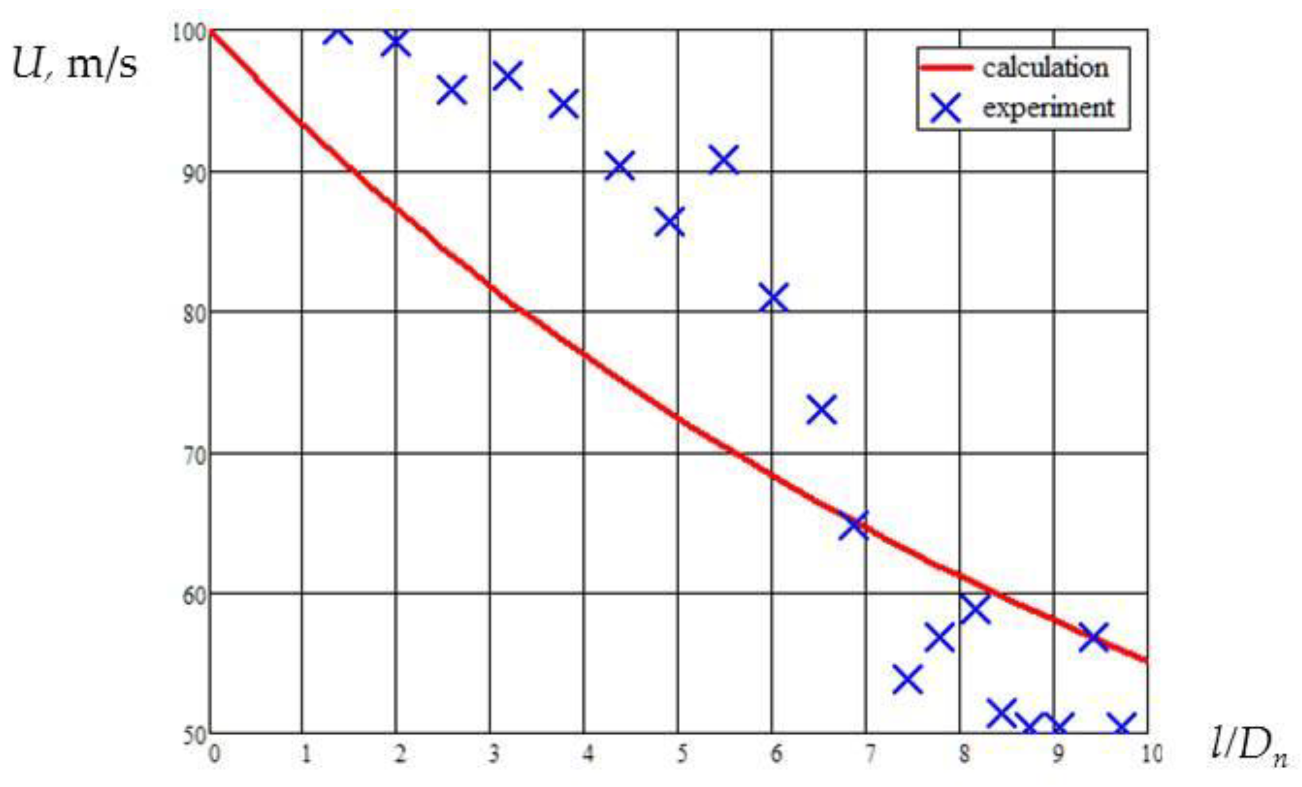
Figure 12 shows a comparison of the velocity calculated from (8) with the experimental data. A rather large spread of experimental data is explained by the difficulty of accurately selecting a certain point of the ring for “tracking” the speed.

4. Conclusions

The experimental data illustrate the possibilities of the presented author’s technical solutions for use in the study of ballistics, mechanics, and dynamics of gaseous media. Their use increases the efficiency of scientific research in the field of fundamental and applied research in the field of physics of fast processes.
A series of frames from video files of the physical phenomena considered in the work are presented. The possibility of studying the mechanisms of transition from combustion to detonation using an innovative optical method for recording fast processes is shown. The dynamics and stages of the phenomenon of detonation transfer through a certain size of the gap filled with various rheological media (air, water) are demonstrated. The picture of the cavitation process at the stage of the detonation wave exit to the water surface is revealed and detailed. A variant of verifying the solution to the problem of forming a vortex ring using the results of visualizing the physical process of forming a ring is demonstrated.
The paper demonstrates new possibilities for analyzing the dynamics of gaseous media due to the detailed registration of the visual picture of the ballistic process. The novelty of the presented visualization technology manifests itself when watching video files. In this case, the visual features of the dynamics and stages of the observed phenomena are more clearly distinguished. The results can be easily correlated with computer visualization data. In the last five years, based on the use of the technology of visualization of ballistic processes, with the participation of the authors, a number of research works were carried out using detailed video recordings of the realized physical phenomena. As a result of the completion of the research cycle, the phenomenology of the phenomena was revealed, and the virtual models of these processes were verified. One of the options for studying the process of vortex ring formation is presented in this work. The technology and launcher presented in this work were awarded two silver medals in 2018 at the XXI International Salon of Inventions and Innovative Technologies.

Author Contributions

Conceptualization, M.S.; methodology, V.S. and D.L.; software, D.L.; validation, M.S. and D.L.; formal analysis, V.S.; investigation, M.S.; resources, V.S.; data curation, D.L.; writing—original draft preparation, M.S.; writing—review and editing, M.S.; visualization, D.L.; supervision, M.S.; project administration, V.S.; funding acquisition, V.S. All authors have read and agreed to the published version of the manuscript.

Funding

This research received no external funding.

Institutional Review Board Statement

Not applicable.

Informed Consent Statement

Not applicable.

Data Availability Statement

Not applicable.

Acknowledgments

The authors are grateful to the staff of the Department “High-Precision Airborne Devices” of the Bauman Moscow State Technical University and D.V. Gelin, D.A. Lysov, V.A. Markov, and A.V. Petyukov for their active participation in the experiments and for the data provided.

Conflicts of Interest

The authors declare no conflict of interest.

References

  1. Lee, J.H.S. The Detonation Phenomenon; Cambridge University Press: Cambridge, UK, 2008; pp. 204–370. [Google Scholar]
  2. Huang, Y.; Green, M.A. Detection and tracking of vortex phenomena using Lagrangian coherent structures. Exp. Fluids 2015, 56, 147. [Google Scholar] [CrossRef]
  3. Riedmann, H.; Banuti, D.; Ivancic, B.; Knab, O.; Hannemann, K. Modeling of H2/O2 single-element rocket thrust chamber combustion at sub- and supercritical pressures with different computational fluid dynamics tools. Prog. Propuls. Phys. 2019, 11, 247–272. [Google Scholar] [CrossRef] [Green Version]
  4. Zhukov, V.P. Extended Eddy-Dissipation Model for Modeling Hydrogen Rocket Combustors. Combust. Sci. Technol. 2020, 60, 969–975. [Google Scholar] [CrossRef] [Green Version]
  5. Volkov, K.N.; Zapryagaev, V.I.; Emelyanov, V.N.; Gubanov, D.A.; Kavun, I.N.; Kiselev, N.P.; Teterina, I.V.; Yakovchuk, M.S. Visualization of Physical and Mathematical Modeling Data in Gas Dynamics; FIZMATLIT: Moscow, Russia, 2018; p. 360. ISBN 978-5-0221-1774-6. [Google Scholar]
  6. Wang, J.-P.; Zhou, R.; Wu, D. Progress of continuously rotating detonation engine research. Chin. J. Aeronaut. 2015, 29, 12–25. [Google Scholar] [CrossRef]
  7. Volkov, K.N. Methods for Visualizing Vortex Flows in Computational Gas Dynamics and their Application in Solving Applied Problems. Sci. Tech. Bull. Inf. Technol. Mech. Opt. 2014, 3, 1–11. [Google Scholar]
  8. Znamenskaya, I.A. Interaction of Numerical and Experimental Flow Visualization. Sci. Vis. 2013, 3, 1–16. [Google Scholar]
  9. Ristic, S. A View in the Invisible. Theor. Appl. Mech. 2013, 40, 87–119. [Google Scholar] [CrossRef] [Green Version]
  10. Tarasov, V.F.; Yakushev, V.I. Experimental Investigation of Impurity Transport by a Turbulent Vortex Ring. J. Appl. Mech. Tech. Phys. 1974, 1, 130–136. [Google Scholar]
  11. Kindracki, J.; Kobiera, A.; Wolanski, P.; Gut, Z.; Folusiak, M.; Swiderski, K. Experimental and Numerical Study of the Rotating Detonation Endgine in Hydrogen Air Mixture. Prog. Propul. Phys. 2011, 2, 555–582. [Google Scholar]
  12. Golovastov, S.V.; Bivol, G.Y. Deficiency of stationary detonation wave velocity in hydrogen-oxygen mixtures in a subcritical detonation tube. Mech. Eng. Comp. Technol. 2017, 12, 22–31. [Google Scholar]
  13. Sotskiy, M.Y.; Gelin, D.V.; Krutov, I.S.; Lysov, D.A.; Markov, V.A.; Markov, I.V.; Chetvernin, M.Y. New Visualization and Measurement Techniques for Ballistic Processes and Dynamic Flows. J. Appl. Mech. Tech. Phys. 2019, 60, 969–975. [Google Scholar] [CrossRef]
  14. Levin, D.P.; Selivanov, V.V. Possibility of Vortex Ring Use for Non-Lethal Effect. In Proceedings of the 5th European Symposium on Non-Lethal Weapon, Ettlingen, Germany, 11–13 May 2009; Available online: https://v3.globalcube.net/clients/ewgv1/content/medias/symposia/05_ettlingen/sy05programme.pdf (accessed on 17 August 2021).
  15. Alekseenko, S.V.; Kuibin, P.A.; Okulov, V.L. Introduction to the Theory of Concentrated Vortices; Institute of Thermophysics SB RAS: Novosibirsk, Russia, 2003; p. 504. ISBN 5-89017-027-9. [Google Scholar]
  16. Akhmetov, D.G.; Kisarov, O.P. Hydrodynamic structure of a ring vortex. J. Appl. Mech. Tech. Phys. 1966, 4, 32–39. [Google Scholar]
  17. Onufriev, A.T. Theory of motion of a vortex ring under the action of gravity. The rise of the atomic explosion cloud. J. Appl. Mech. Tech. Phys. 1967, 2, 3–15. [Google Scholar]
Figure 1. The active unit of the setup (a) and the initial phase of the process (b) of the effect of the detonation products of the hydrogen–oxygen mixture on the probe during its acceleration in the guiding element.
Fluids 06 00290 g001
Figure 2. Separate video recordings of the detonation front movement along the annular tube to the working volume of the hydrogen–oxygen mixture.
Fluids 06 00290 g002
Figure 3. Separate video recordings of the detonation transfer process through an air gap of 230 mm from the lower to the upper volume of the hydrogen–oxygen mixture (active volume 350 mm long).
Fluids 06 00290 g003
Figure 4. Selected video recordings of the detonation transmission process through an air gap of 237 mm from the lower to the upper volume of the hydrogen–oxygen mixture (active volume 400 mm long).
Fluids 06 00290 g004
Figure 5. Selected video recordings of the detonation transfer process through a 10 mm water gap from the lower to the upper volume of the hydrogen–oxygen mixture (active volume 400 mm long).
Fluids 06 00290 g005
Figure 6. Separate video recording frames of cavitation on the surface of the water gap during the period of the shock wave emerging from the detonation of the hydrogen–oxygen mixture.
Fluids 06 00290 g006
Figure 7. Separate video recording frames of the process of forming a gas ring after the detonation of a hydrogen–oxygen mixture in the guide element.
Fluids 06 00290 g007
Figure 8. The main dimensions of the vortex ring: D (R)—the outer diameter (radius) of the vortex—the distance between the centers of the vortex spirals; a—the radius of the vortex core; b1 and b2 —the dimensions of the sides of the “atmosphere” of the vortex ring (if it is taken as an ellipsoid); δ—the width of the vortex path.
Fluids 06 00290 g008
Figure 9. Diagram of the vortex ring formation process: δ —the thickness of the boundary layer; R—the radius of the VR (defined as the radius of a circle with zero velocities in the coordinate system associated with the VR); a—the radius of the core of the VR (the radius of the vortex thread).
Fluids 06 00290 g009
Figure 10. Distribution of velocity components over the section of the vortex ring.
Fluids 06 00290 g010
Figure 11. Distribution of velocity (left) and pressure (right) in the Rankin vortex [7].
Fluids 06 00290 g011
Figure 12. Comparison of the calculated dependence of the absolute velocity of the vortex ring on the relative distance with experimental data.
Fluids 06 00290 g012
Table 1. The range of variation of unit parameters.
V, m/sdV/dt, m/s2E, J
20.01–52.25610–42828–96
Publisher’s Note: MDPI stays neutral with regard to jurisdictional claims in published maps and institutional affiliations.