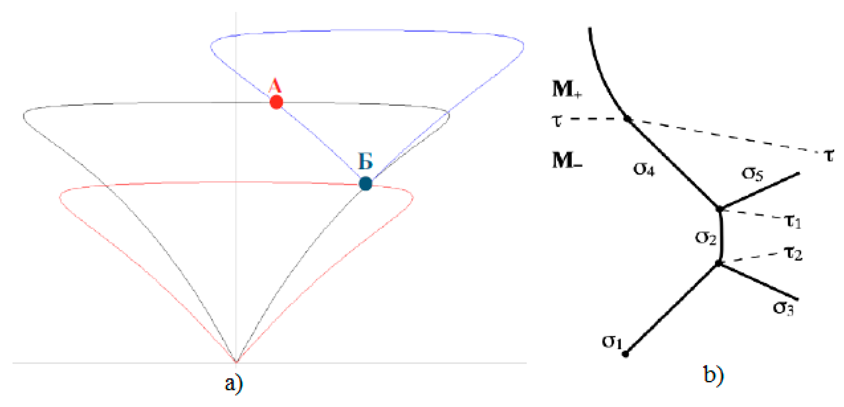
Abstract
The refraction of an oblique shock wave on a tangential discontinuity dividing two gas flows with different properties is considered. It is shown that its partial reflection occurs with the exception of the geometrical diffraction of an oblique shock. Another oblique shock, expansion wave or weak discontinuity that coincides with the Mach line can act as a reflected disturbance. This study focuses on the relationships that define the type of reflected discontinuity and its parameters. The domains of shock wave configurations with various types of reflected discontinuities, including characteristic refraction and refraction patterns with a reflected shock and a reflected rarefaction wave, are analyzed. The domains of existence of various shock wave structures with two types of reflected disturbance, and the boundaries between them, are defined. The domains of parameters with one or two solutions exist for the characteristic refraction. Each domain is mapped by the type of refraction with regard to the Mach number, the ratio of the specific heat capacities of the two flows and the intensity of a refracted oblique shock wave. The conditions of the regular refraction and the Mach refraction are formulated, and the boundaries between the two refraction types are defined for various types of gases. Refraction phenomena in various engineering problems (hydrocarbon gaseous fuel and its combustion products, diatomic gas, fuel mixture of oxygen and hydrogen, etc.) are discussed. The result can be applied to the modeling of the shock wave processes that occur in supersonic intakes and in rotating and stationary detonation engines. The solutions derived can be used by other researchers to check the quality of numerical methods and the correctness of experimental results.
1. Introduction
The processes by which a gas dynamic system with parameters f1 transforms into a system with parameters f2 are called shock wave processes, where f1 and f2 are some gas dynamic variables before and behind the gas dynamic discontinuity.
Gas dynamic waves and discontinuities can be divided into two large groups. The first group includes normal waves and discontinuities through which the gas flows, and they are referred to as shock wave processes. The second group includes contact and tangential discontinuities, through the surfaces of which the gas does not flow, and they cannot be considered shock wave processes. A tangential discontinuity is also called a sliding line because it can separate the flows of various gases with different densities, velocities and temperatures. The static pressure on opposite sides of the tangential discontinuity is always the same. The tangential discontinuity is usually denoted by the symbol τ. It appears in shock wave structures formed as a result of the interaction of shock waves with each other and with solid walls. The reason for the formation of tangential discontinuity lies in the fact that at different shock waves, included in the shock wave structures, the value of the total pressure loss and, accordingly, the flow rate is different.
The theory of gas dynamic discontinuities consists of two large sections: the theory of the interference (intersections, interactions) of discontinuities and waves with each other, and the theory of their refraction (refraction) on contact and tangential discontinuities [1]. Contact and tangential discontinuities cannot intersect with each other.
The problem of refraction of an oblique shock wave on a tangential discontinuity is consistently presented in [2]. There are cases of regular refraction (RRefr) [3] and Mach (irregular) refraction (MRefr) [4]. In the first case, the flow is always supersonic. In the second case, there are regions where the Mach number is less than unity (M < 1).
The theory of regular refraction is developed in [5]. A number of studies have been devoted to the experimental determination of both regular and irregular refraction [6,7,8]. An attempt to systematize the flow patterns arising during refraction, both regular and Mach, is made in [4,9]. A similar problem is solved in a non-stationary formulation in [10].
The interaction of an oblique shock wave with the interface between the media leads to the development of complex non-stationary shock wave configurations [6,7,8,11]. The passage of a shock wave through a medium containing gas bubbles or liquid droplets leads to curvature of the wave front, shock wave interactions and the development of multiple vortices.
A theoretical analysis of the emerging shock wave configurations using shock poles is given in [12]. The boundaries of the regions of existence of refraction modes with a rarefaction wave and the region of existence of refraction with a reflected shock wave, with a change in the angle of inclination of the contact discontinuity, are determined. The generation of vorticity and the evolution of vortex structures are discussed, as well as the grid convergence of the solution [13]. An exact solution to the problem of refraction of a plane shock wave at a contact discontinuity (regular case) is given, and the suppression of the Richtmyer–Meshkov instability upon application of a magnetic field is discussed in [14,15]. Exact solutions of the problem are given in both one-dimensional and two-dimensional cases of regular refraction of a shock wave at a contact discontinuity.
Various modes of shock wave refraction using experimental and numerical methods are studied in [3]. Numerical calculations are carried out on the basis of a TVD scheme of the second order of accuracy and an approximate method for solving the Riemann problem. The calculated data are in good agreement with the results of measurements and the results of theoretical analysis, with the exception of the high Mach numbers of the incident shock wave.
Two-dimensional calculations based on the Godunov-type scheme of the second order of accuracy are carried out in [16]. The density discontinuity is oriented at an angle of 75 degrees to the horizontal, and the Mach number of the shock wave is 1.2. The MUSCL scheme is used in [17] to calculate the flow structure at different angles of inclination of the discontinuity. Various difference schemes are compared in [18].
A numerical study of the Richtmyer–Meshkov instability in the interaction of a strong shock wave with a discontinuity in the density of a rectilinear and sinusoidal shape is carried out in [19]. The refraction of a shock wave upon its interaction with a near-wall layer of a heated gas is investigated in [20]. A wide range of issues related to the interaction of shock waves with contact discontinuities and the formation of the Richtmyer–Meshkov instability are discussed in [21]. The refraction of a spherical shock wave at the air–water interface is considered in [22]. The results of calculations using the through-counting scheme and using the level function method are compared, which makes it possible to single out the contact gap and trace its evolution over time. The application of discontinuity detection schemes as applied to the refraction of shock waves at the interfaces between media is discussed in [23,24].
This study exploits notations and theoretical approaches developed in previous works. For example, theoretical solutions related to the interaction of an oblique shock wave and a Prandtl–Meyer expansion or compression wave were derived in [25]. Numerical simulation of the interaction of shock waves in steady viscous flows was studied in [26] for gas with a low ratio of specific heat capacities. Viscous effects on shock wave configuration for different Reynolds numbers and the non-uniqueness of numerical solutions are discussed. Results of the numerical simulation of steady axisymmetric supersonic flows in convergent conical nozzles and overexpanded jets are presented in [27]. The formation of triple-shock configurations is analogous to the configurations known for the steady inviscid two-dimensional flows where the irregular reflection of a wedge-generated shock from a wall with Mach stem formation occurs. In the four-wave flow pattern, the curvatures of the tangential discontinuity and the Mach front at the triple point are finite [28]. When the three-wave flow pattern is realized, the curvatures of the tangential discontinuity and both wave fronts at the triple point are infinite.
For Mach reflection in steady supersonic flow, the slip line and reflected shock wave from the triple point are disturbed by secondary Mach waves generated over the slip line and by the expansion fan from the rear wedge corner. Analytical expressions for the shape of the curved slip line and reflected shock wave are derived in [29]. An analytical model for the configuration of Mach reflection due to the interaction of two-dimensional steady supersonic flow over asymmetric wedges is presented in [30]. The asymmetrical Mach reflection configuration is studied analytically in [31]. The study uses an asymmetrical model extended from a recent symmetrical model and accounts for the new features related to asymmetry of the two wedges. The accuracy of the model is checked by numerical simulation.
The stability of the nonlinear wave structure caused by the interaction of an incident shock with an interface separating two different media was studied in [32]. The reflection and refraction problem was reduced to a free boundary value problem, where the unknown reflected shock and refracted shock are free boundaries, and the deflected interface is to be determined. The results obtained indicate that the wave structure and the flow field for the reflection and refraction problem in this case are conditionally stable. The refraction of shocks on the interface for 2D steady compressible flow is discussed in [33]. The 2D steady potential flow equation is employed to describe the motion of the fluid. Supercritical conditions are described theoretically and reproduced numerically using highly resolved inviscid simulation in [34].
Shock refraction induces a package of reflected shock waves and inclines the air intake flow in a non-optimal direction. This leads to an off-rated operation of the air intake system and, sometimes, to its breakdown. There are currently many research papers on CFD. Significant progress has already been made in the simulation of complex compressible flows. The major difficulties that arise are linked to boundary conditions at the fluid and solid interface, most significantly when the flow interfering with a solid is supersonic. The study [11], along with the works [6,7], are considered reference experimental works on refraction. There are no other studies in which experiments were carried out with such thoroughness.
Although many theoretical, experimental and computational studies have been published in recent years, research on different types of refraction is far from complete. In this study, the domains of existence of various shock wave structures with two types of reflected disturbance, and the boundaries between them, are defined. The conditions of the regular refraction and the Mach refraction are formulated, and the boundaries between these two refraction types are defined for various types of gases.
This study presents analytical solutions that can be used by other researchers to check the quality of numerical methods and the correctness of experimental results. The Busemann method of analysis in the plane of heart-shaped curves and a computational solution of dynamic compatibility equations for conditions on tangential discontinuity are applied. The boundaries between the regular and Mach refractions are found. Domain charts, drawn for characteristic and two other types of regular refraction patterns, support the regular refraction case. The calculations are carried out for Mach numbers M = 1–5 and various combinations of ratios of specific heat capacities of two flows: 1.67 (monatomic gas), 1.4 (air), 1.11 (hydrocarbon fuel and air mixture), 1.25 (combustion products). Refraction phenomena in various engineering problems (hydrocarbon gaseous fuel and its combustion products, diatomic gas, fuel mixture of oxygen and hydrogen, etc.) are discussed.
The paper is organized as follows. The brief theory of shock wave is considered in Section 2. This section allows us to introduce notations that are useful for further considerations and to present the main equations in compact form. Regular refraction and characteristic refraction are discussed in Section 3 and Section 4. The domains of existence of the theoretical solution can be found in Section 5. Conclusions are drawn in Section 6. The domains of existence of various configurations are given in Appendix A for various Mach numbers and ratios of specific heat capacities.
2. A Brief Theory of an Oblique Shock Wave
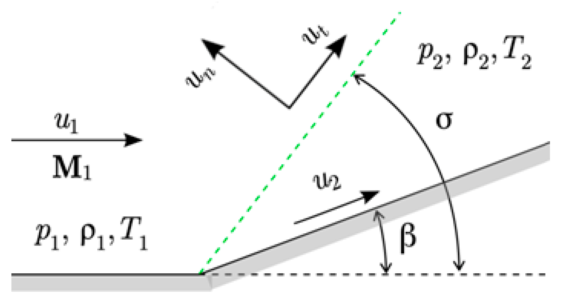
An oblique shock wave in a supersonic flow is a gas dynamic discontinuity (stationary shock wave) located at an angle to the incident flow. A shock located at an angle σ compresses the incoming flow and orientates it at a certain angle β (Figure 1). The angle β is taken with a plus sign if it is plotted counterclockwise from the free stream velocity vector (such a shock is referred to as left-handed), and with a minus sign if it is plotted clockwise (such a shock is referred to as right-handed). An oblique shock is characterized by a static pressure ratio J = p2/p1 (shock intensity). Subscript 1 corresponds to flow quantities before shock, and subscript 2 corresponds to flow quantities behind shock.
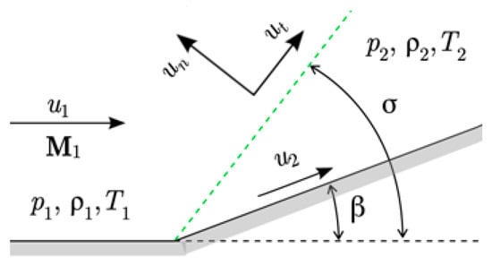
Figure 1.
Oblique shock wave.
Oblique shocks are reflected from the walls, intersect with other shock waves and refract at tangential discontinuities. If there are many shock waves in the flow, they are usually numbered and the shock direction indicated with arrows—for example, or . Left-handed shocks are indicated by an arrow pointing to the left, and right-handed shocks are indicated by an arrow pointing to the right. The quantities behind the corresponding shock are indicated by a number. For example, the quantities behind the shock are denoted by M1 and p1, and the flow quantities behind the shock are denoted by M2 and p2.
The mass balance, momentum balance and energy balance equations can be written in the following form:
Continuity equation
Momentum equation in normal direction
Momentum equation in tangential direction
Energy equation
Here, un and ut are the projections of the velocity vector onto the directions normal to the discontinuity plane and tangential to it (Figure 1).
Equation (2) directly relates the change in pressure p and dynamic pressure ρu2 on a normal shock when the angle of inclination of the shock is σ = 90°. Using the Mach number M and the expression for the speed of sound (γ is the adiabatic index, γ = cp/cv, cp is the specific heat capacity at constant pressure, cv is the specific heat capacity at constant volume), and also by expanding the velocity vector of the incoming flow into the components un and ut. Taking into account the fact that u1t = u2t, after simple transformations from (1) and (3), one can obtain an equation that relates the intensity of the shock to the angle of its inclination:
The relation between angles β and σ takes the form
Here, . This is the limit of the ratio of densities on the jump as J→∞.
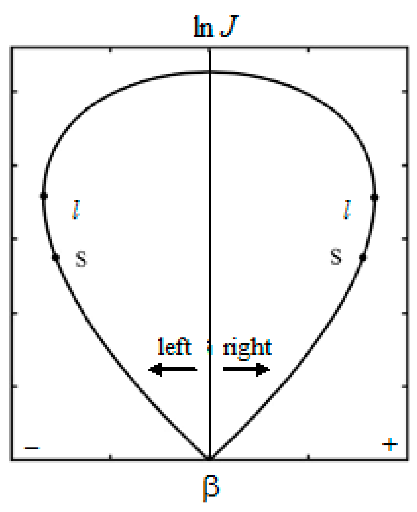
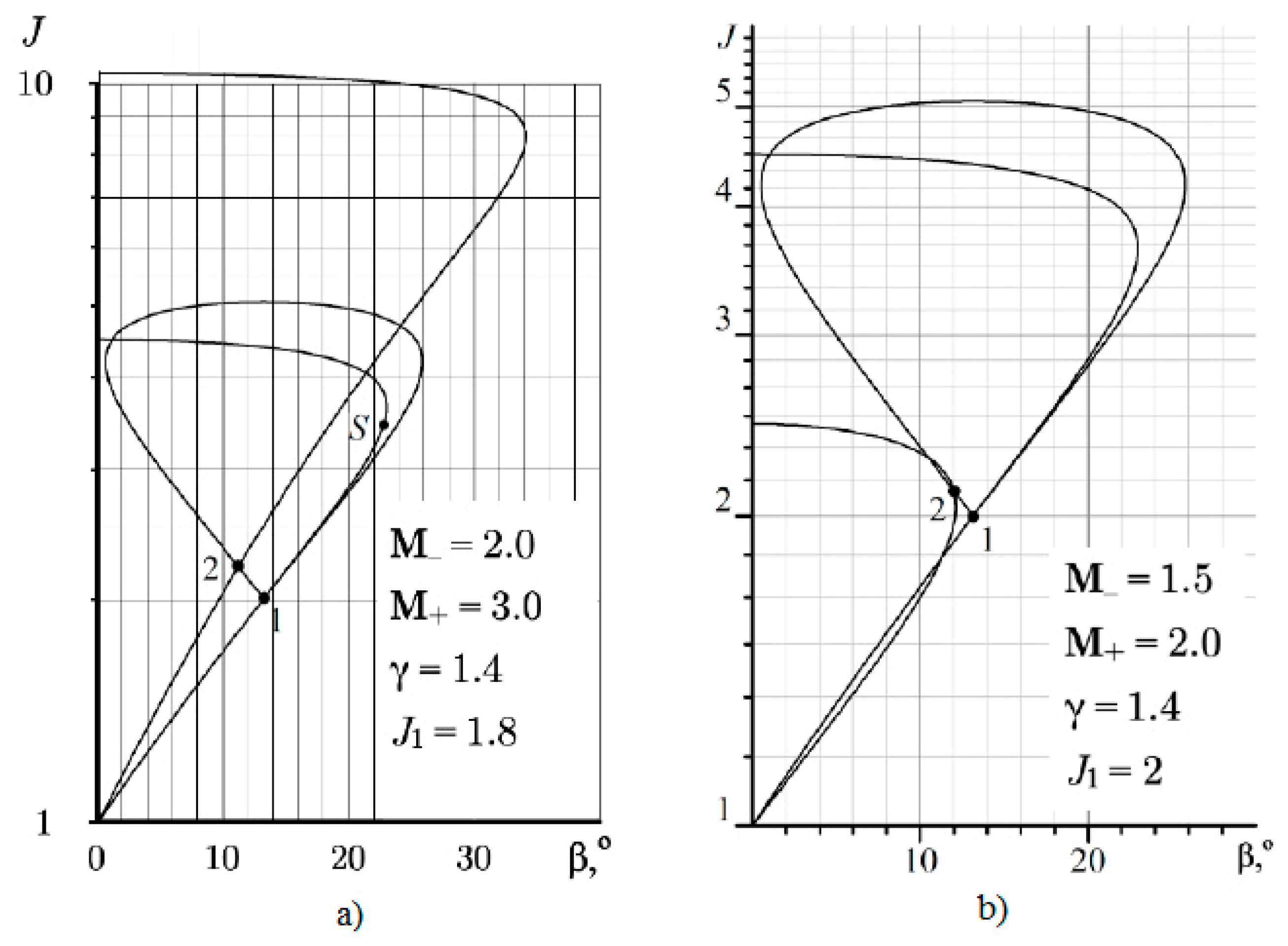
Equations (5) and (6) for a given M link J, β and σ. These equations are referred to as dynamic compatibility conditions on the oblique shock wave. These equations for a given freestream Mach number define a closed curve (heart-shaped curve) as shown in Figure 2. Since each M number has its own curve, shock polars are also called isomachs. It is convenient that the polar begins at the origin of coordinates [0, 0]; therefore, it is usually constructed in the variables (lnJ, β).
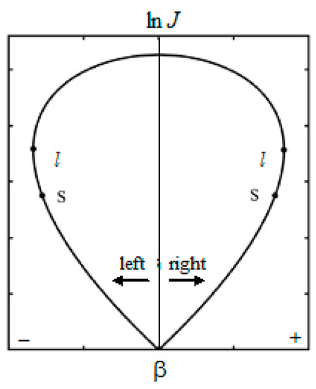
Figure 2.
Shock polar (Busemann curve). The point l corresponds to the shock with the maximum possible flow turning angle, and the point s is the sonic point.
3. Regular Refraction
The scheme of regular refraction is shown in Figure 3, where σ1 is the incident shock wave, σ2 is the refracted shockwave, ω3 is the reflected rarefaction wave, σ3 is the reflected shockwave, ν3 is the reflected weak discontinuity, τ is the tangential discontinuity, ← is the left-moving discontinuity, → is the right-moving discontinuity, T is the refraction point, and M is the Mach number. The subscript + denotes the flow quantities in original flow above τ, and subscript—denotes the flow quantities in the original flow under τ. For example, M+ and M− denote Mach numbers in the relevant flow regions (above and below tangential discontinuity).

Figure 3.
Regular refraction of oblique shock wave σ1 on tangential discontinuity τ: (a) refraction with reflected rarefaction wave, (b) refraction with reflected shock wave, (c) characteristic refraction, where the reflected discontinuity is the discontinuous characteristic.
Refraction of the shock wave σ1 on the tangential discontinuity leads to an increase (Figure 3a) or decrease (Figure 3b) in its inclination angle. In the particular case in which the reflected discontinuity is a discontinuous characteristic, only the curvature of the incident shock wave changes. This refraction is called characteristic.
The equation of regular refraction is written as
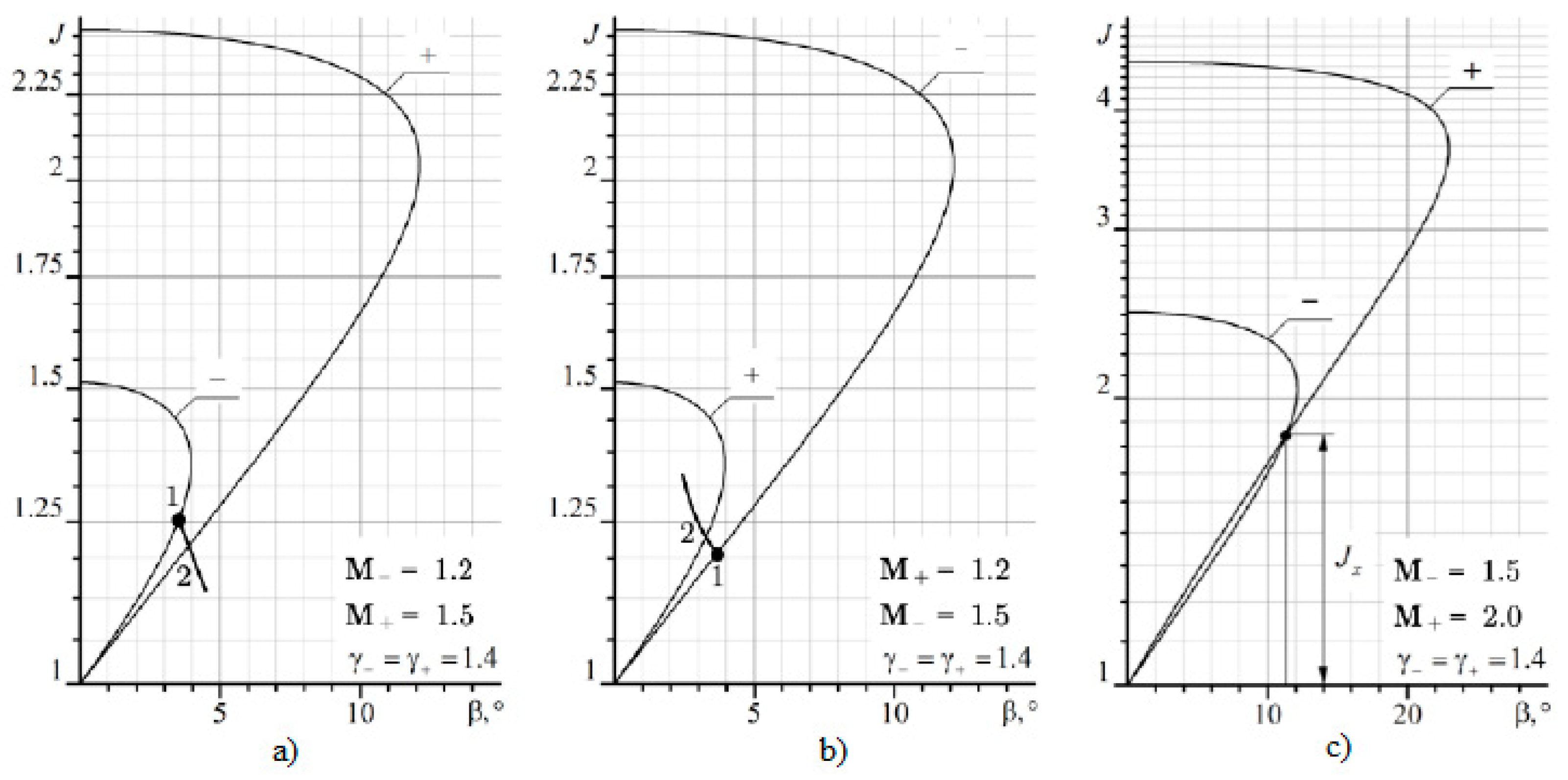
The first equation corresponds to refraction with a reflected rarefaction wave (Figure 3a), the second equation corresponds to refraction with a reflected shock wave (Figure 3b), and the third equation corresponds to characteristic refraction (Figure 3c). Three types of regular refraction on a shock polar are presented in Figure 4.
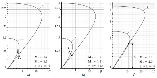
Figure 4.
Three types of regular refraction on shock polar: (a) refraction with reflected rarefaction wave, (b) refraction with reflected shock wave, (c) characteristic refraction.
To solve Equation (7), the conditions of dynamic compatibility are used, written in the form of the equality of pressures p and the inclination angles of the velocity vector at the tangential discontinuity behind the point T. These conditions are written as
Subscript 2 denotes flow quantities behind the refracted shock wave, and subscript 3 denotes flow quantities behind the reflected discontinuity (Figure 3).
A partial case of regular refraction is characteristic refraction (Figure 3c), when the polar − and polar + intersect each other (Figure 4c). Since the reflected discontinuity is a discontinuous characteristic (weak discontinuity of the second order), the slope of the shock σ1 does not change. Then, the conditions of dynamic compatibility on τ are written in the form of the equality of the angles of flow turn:
The flow turn angle at the shock is expressed by the formula
Here, γ is the ratio of specific heat capacities at constant pressure and constant volume, and ε = (γ − 1)/(γ + 1). The maximum intensity of the shock wave is Jm = (1 + ε)M2 − ε.
βσ(γ−, M−, Jc) = βσ(γ+, M+, J).
For the case when a reflected discontinuity is a shock wave, an equation similar to Equation (9) is written in the form
Subscripts 1 and 2 denote relevant shock waves (Figure 3b) and the flow quantities behind them, and subscript ^ denotes the flow quantities behind a shock wave.
The Mach number behind the incident shock in Equation (11) is found from the relation
For the cases shown in Figure 3a and Figure 4a, when the reflected discontinuity is a rarefaction wave, the conditions of dynamic compatibility take the form
In Equation (13), for Mω, J2/J1 is substituted for J, and is substituted for M. Then, the Prandtl–Mayer function ω(M) is found for Mω and .
4. Characteristic Refraction
In different technical problems, where there is refraction on the mixing layer or the interface between two media, different types of reflected discontinuities are preferable. Thus, with a reflected shock wave, the initial shock is enhanced, which is good for supersonic air intakes and wave compressors but not good in cases where a shock wave attenuation is required [35,36]. If it is required to protect a certain device from the impact of a shock wave, then refraction with a reflected rarefaction wave is preferable. Characteristic refraction separates these two cases.
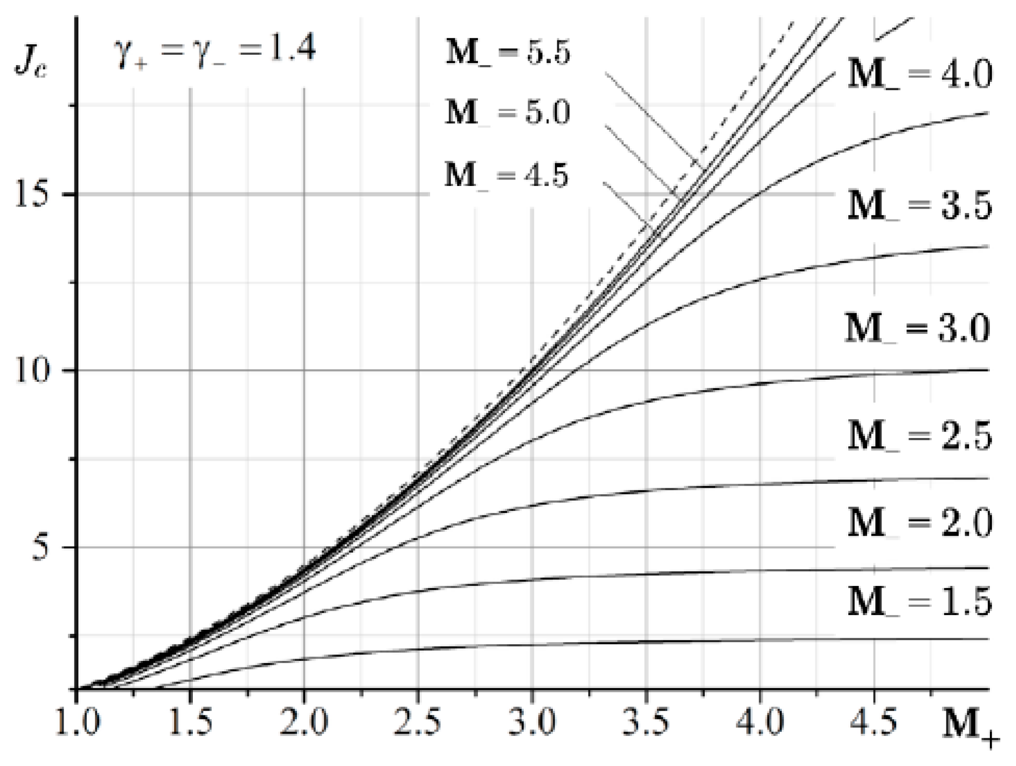
The characteristic refraction corresponds to the intersection of shock polar J(M+) and shock polar J(M−), which is realized at a strictly defined intensity of the initial oblique jump Jc = Jc(M+, M–, γ+, γ–) at which Equation (9) is satisfied. The condition for the equality of the intensities of the shocks Jc(M+, γ+) = Jc(M–, γ–) reduces to the cubic equation
where
If the same gas flows on both sides of τ, then γ+ = γ–, ε+ = ε–, Γ+ = Γ–, and Equation (8) is simplified:
Substituting (15) into (14) and excluding the solution z = −(1 − ε) that has no physical meaning, the unique solution is
Equation (16) determines the intensity of the inlet shock, at which the characteristic refraction is realized, provided that the same gases flow on both sides of the tangential discontinuity.
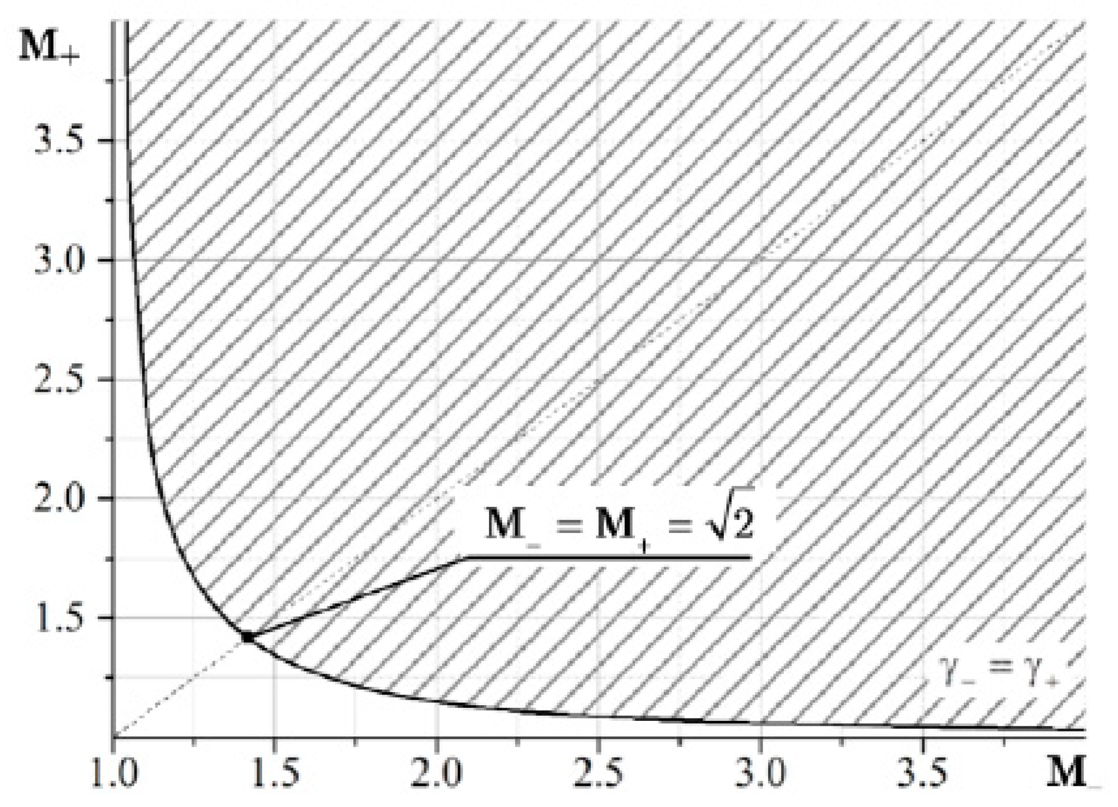
The case when the same gases flow on both sides of τ—for example, air with γ = 1.4—is considered. An important conclusion follows directly from Equation (10) that characteristic refraction is possible if
Formula (17) is interpreted in such a way that the shock polars do not intersect if M < 21/2, since one of them lies completely inside the other (Figure 5).
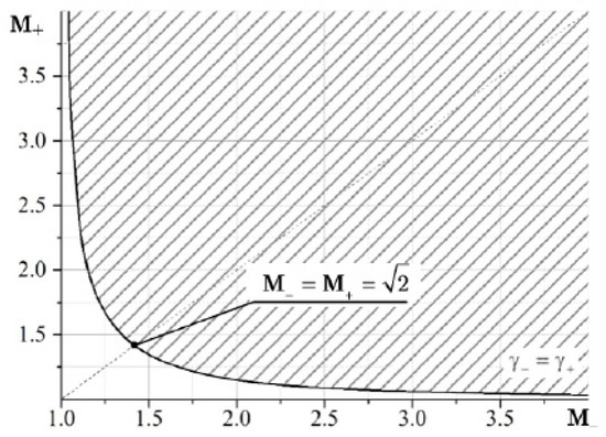
Figure 5.
Domain of existence of characteristic refraction in air (the shaded area).
Equation (17) follows from the condition J > 1, but on the other hand, the condition J < Jm must also be satisfied. Then, both shocks, the original shock σ1 and the refracted shock σ2, must be straight lines. Therefore, the second condition is that curves corresponding to characteristic refraction have an envelope
This corresponds to M– = ∞. Solutions of Equation (16) with limitations (17) and (18) are shown in Figure 6.
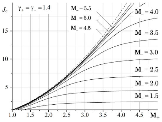
Figure 6.
The values of the intensity Jc of the incident shock for characteristic refraction. The dashed line shows the envelope corresponding to the case when the refracted shock has the maximum intensity J2 = Jm.
In the general case, when γ+ ≠ γ–, it is necessary to solve the cubic Equation (8). Unlike the previous case, the solution can have one to three roots. Since z ≥ 0, it follows from (8) that when one of the roots is equal to zero (z = 0), the polars J(γ–, M–) and J(γ+, M+) have the same derivatives at the origin (Γ– = Γ+), since A0 = 0. From the equality Γ– = Γ+, it follows that, between the numbers M– and M+, there must be a relation
The discriminant of Equation (13) exists if γ+ ≥ γ–. Therefore,
or
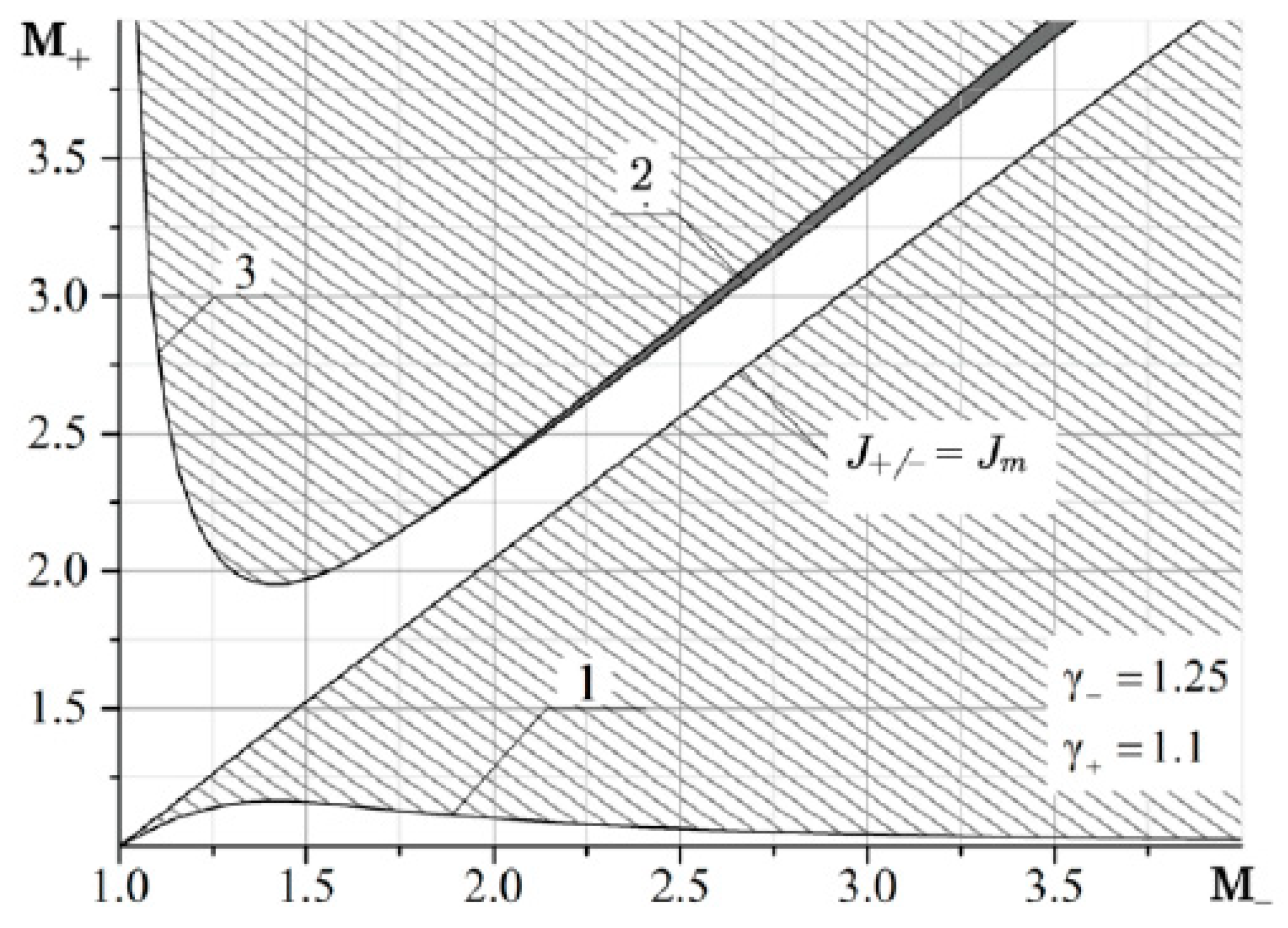
Equations (20) and (21) determine the region of existence of characteristic refraction. The other two roots are obtained by solving the quadratic equation
In Equation (22), the coefficients A are calculated by Formula (14) taking into account the relationship (19) between the Mach numbers M– and M+. These equations allow us to construct the domains of existence (Figure 7).
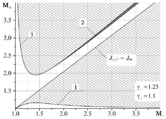
Figure 7.
The domains of existence of characteristic refraction at the interface between the hot hydrocarbon fuel mixture (γ = 1.1) and the products of its combustion (γ = 1.25), where domains 1, 2 and 3 are the first, second and third roots of Equation (8).
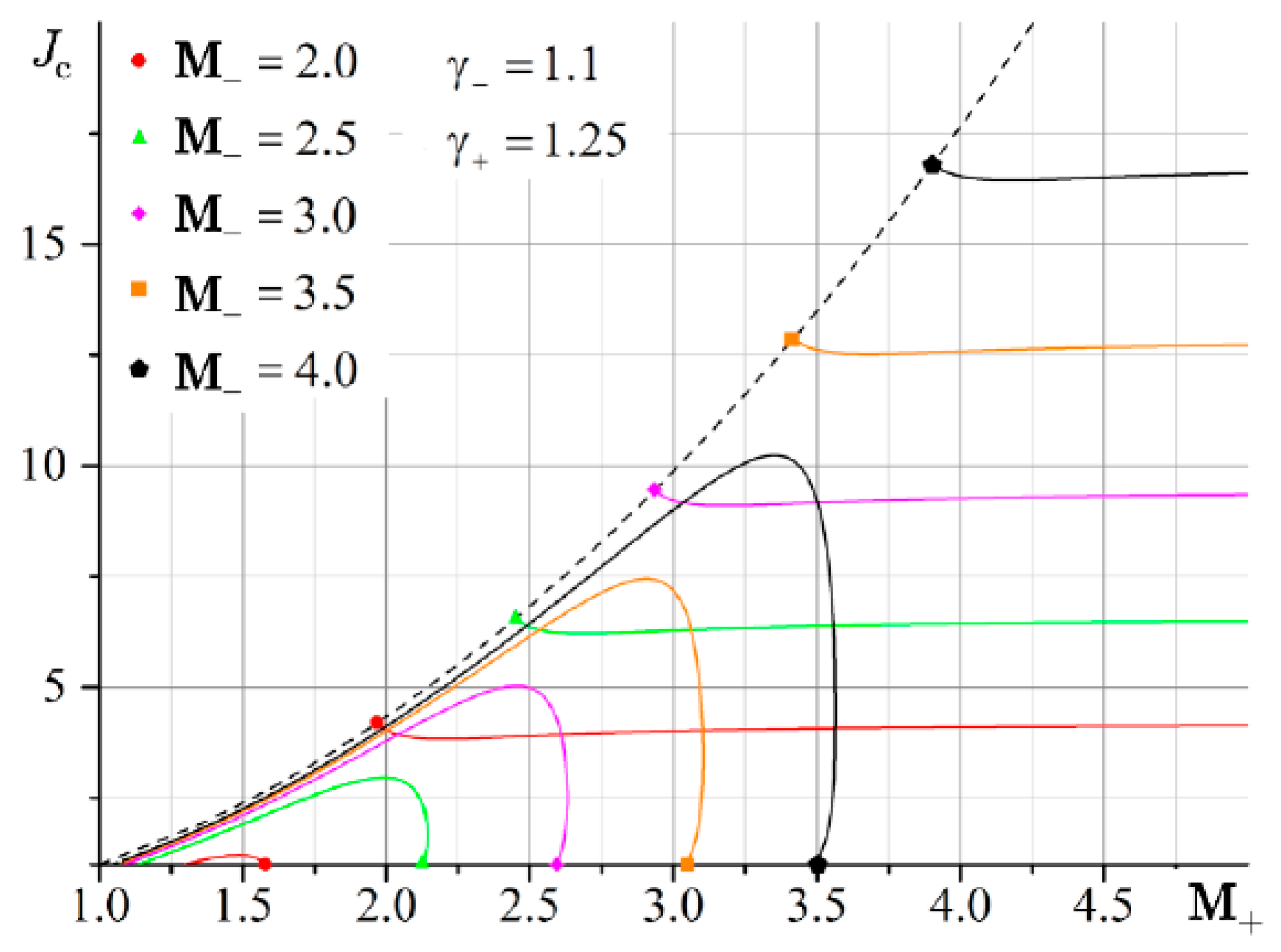
Figure 8 shows the dependence of the intensity of the incident shock wave corresponding to the characteristic refraction. It is seen that there are solutions with one and two roots of Equation (14). The three roots are not physically realized.
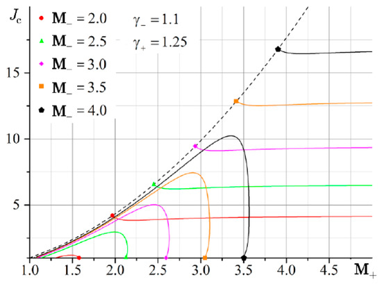
Figure 8.
Dependence of the intensity Jc of the incident shock corresponding to the characteristic refraction on the Mach numbers M– and M+ in flows separated by a tangential discontinuity. The dotted line shows the dependencies corresponding to the case when the refracted shock has the maximum intensity J2 = Jm.
5. Domains of Existence
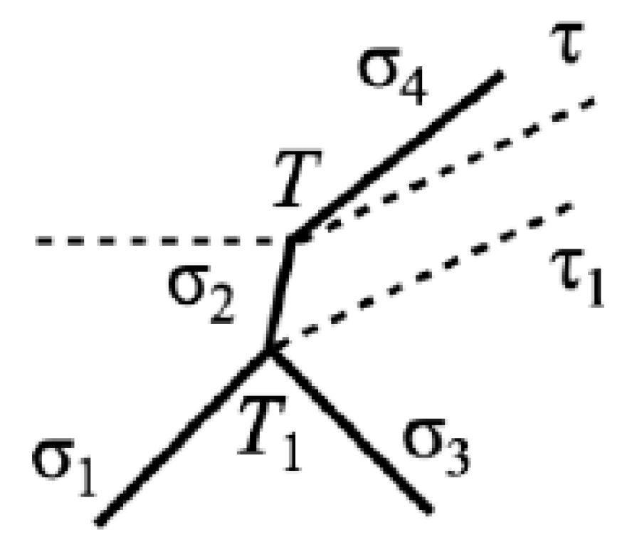
If the intensity of the incident shock is , then it passes the tangential discontinuity with partial reflection. Depending on the intensity of the tangential discontinuity Jτ, the reflected discontinuity r3 can be either a compression shock σ3 or a rarefaction wave ω3. If r3 is a shock wave, then, at certain intensities J1 of the incident shock, the solution of Equation (5) may not exist, since polar (3) emitted from point (1) corresponding to J1 does not intersect with polar (1) (Figure 9). The shock wave structure corresponding to MRef is shown in Figure 10.
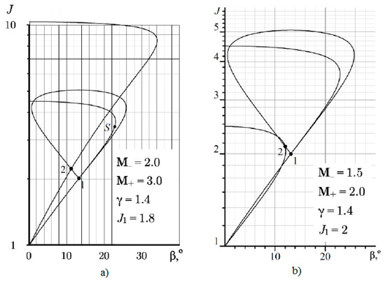
Figure 9.
Regular refraction when the flow behind the reflected flow is supersonic (a) and subsonic (b).
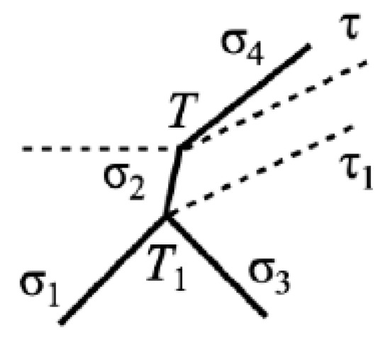
Figure 10.
Shock wave configuration for Mach refraction.
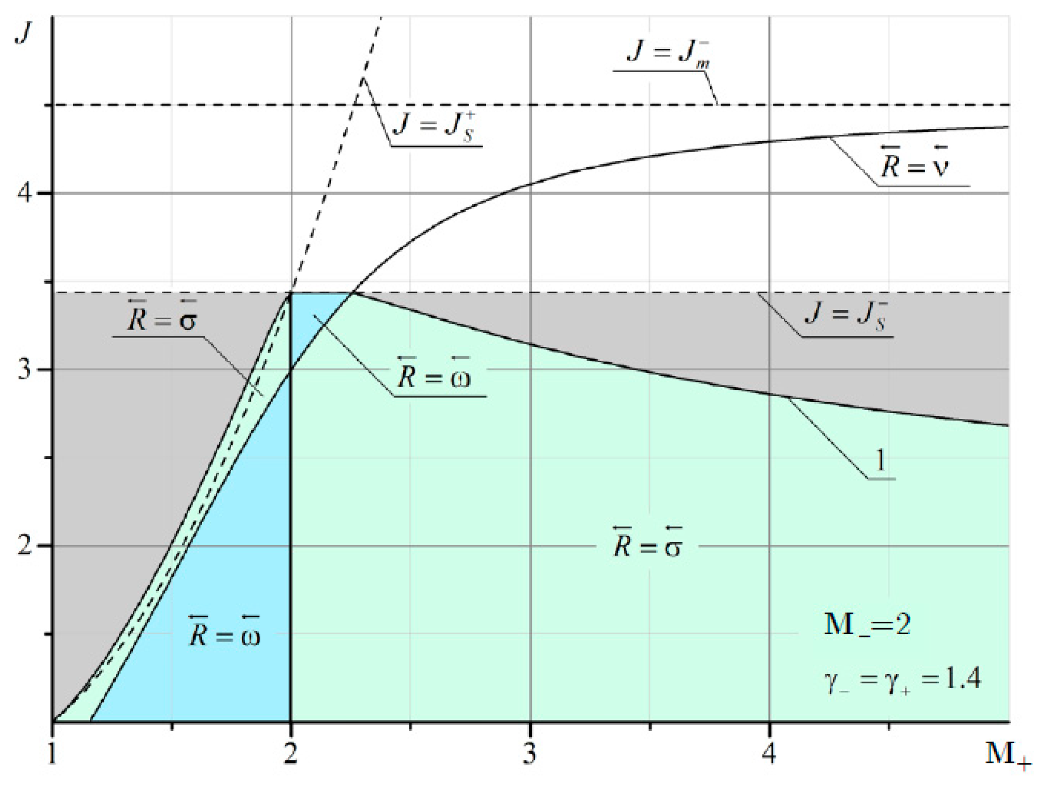
For irregular refraction, the incident shock σ1 branches with the formation of a reflected shock σ3 and a main shock σ2 (the Mach stem). The main shock experiences characteristic refraction on the tangential discontinuity τ. The Mach stem is enclosed between two points, T and T1, from which tangential discontinuities originate, τ and τ1. Figure 11 shows the regions of existence of a shock wave structure with a different type of reflected discontinuity r3 (Figure 1), which are formed during refraction of the shock σ1 at the tangential discontinuity τ.
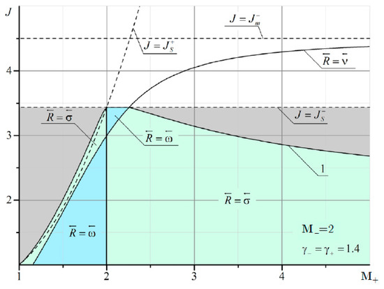
Figure 11.
Domains of existence of various types of hydrocarbons formed during refraction of a shock with intensity J propagating from a flow with a Mach number M− = 2 into a flow with a Mach number M+. The grey area corresponds to irregular refraction with a supersonic flow M1 > 1 behind a shock σ1, and white area corresponds to irregular refraction with a subsonic flow behind a shock σ1.
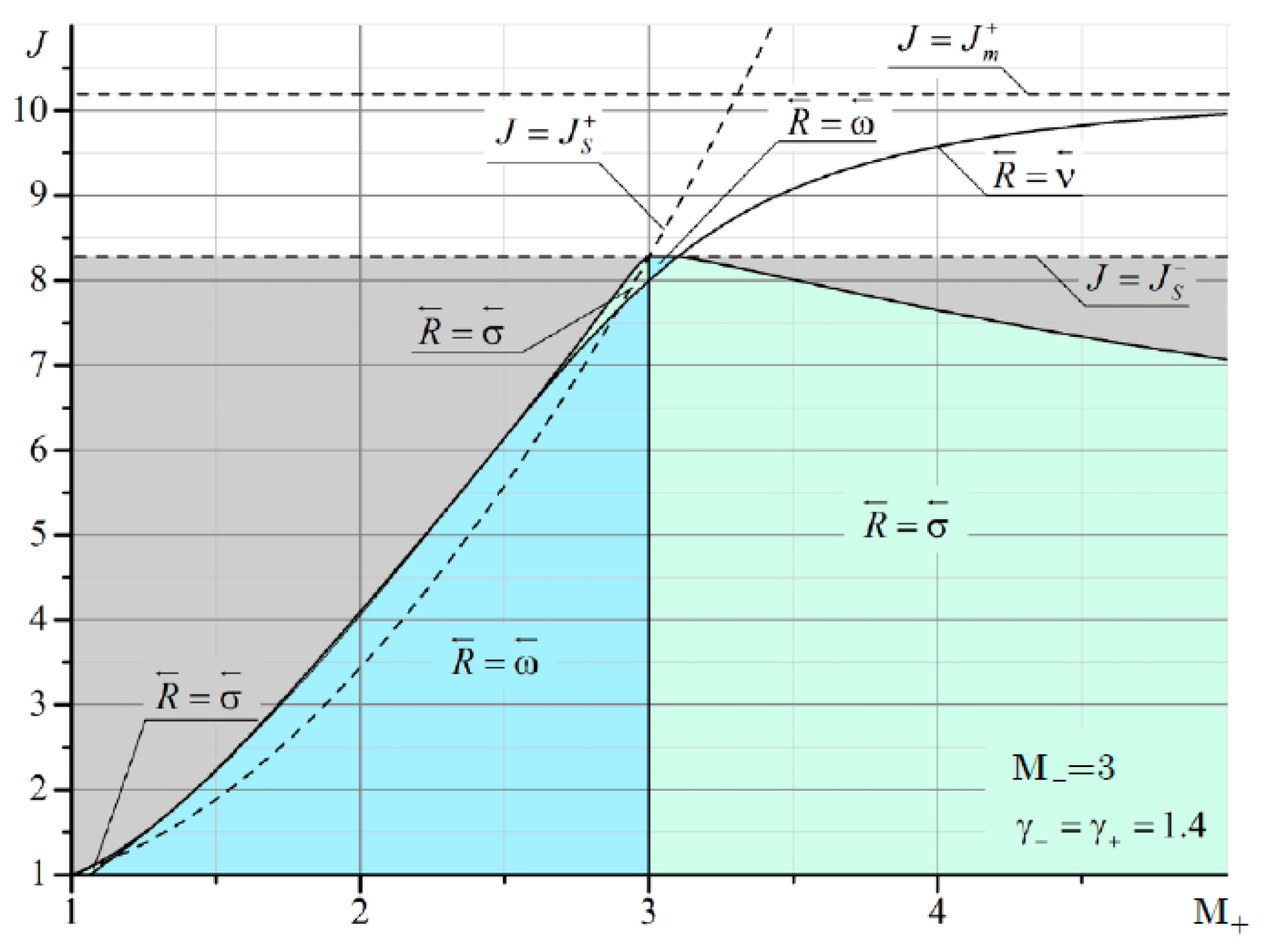
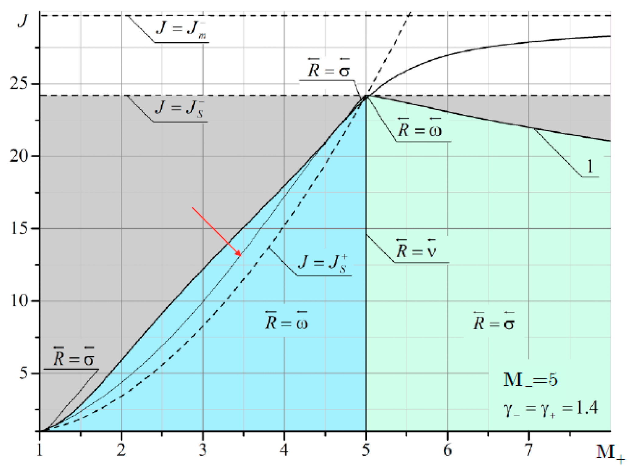
It can be seen that at M– = 2 and M+ < 2, there are quite extensive regions with both the reflected shock wave σ3 and the reflected rarefaction wave ω3. As M– increases, the domains of existence of the reflected σ3 at M+ < M– are significantly reduced (Figure 12 and Figure 13).
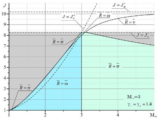
Figure 12.
Domains of existence of various types of hydrocarbons formed during refraction of a shock with intensity J, propagating from a flow with a Mach number M– = 3 into a flow with a Mach number M+.
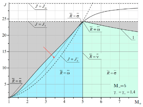
Figure 13.
Domains of existence of various types of hydrocarbons formed during refraction of a shock with intensity J, propagating from a flow with a Mach number of M– = 5 to a flow with a Mach number of M+.
The boundary of irregular refraction with supersonic flow behind the shock σ1 (gray area in Figure 11, Figure 12 and Figure 13) is bounded from above by the intensity of the incoming shock J = Js. It should also be noted that the line corresponding to the characteristic refraction at M+ < M– gradually shifts to the left and enters the MRef region. This is especially noticeable in Figure 13. The red arrow shows a thin line corresponding to the solution in the plane of the shock polar in Figure 14. This line marks the characteristic refraction.
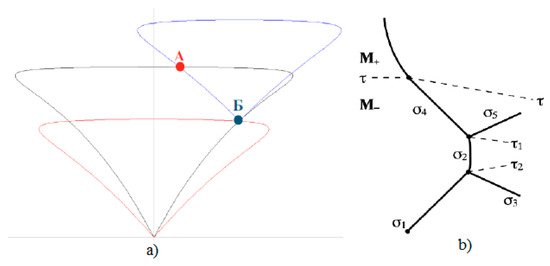
Figure 14.
Ambiguity of the solution on the polar plane: irregular refraction (A), characteristic refraction (B): (a) solutions on the plane of shock polar, (b) shock wave structure corresponding to the Mach refraction MRef.
In the area enclosed between the solid line separating the gray and blue areas and the thin line, the solutions are ambiguous. One solution (point B in Figure 14a) corresponds to characteristic refraction, and the other solution (point A in Figure 14b) corresponds to MRef with the shock wave structure shown in Figure 14b. The flow above τ behind the refracted shock σ4 is subsonic. Between these two lines lies a region with a reflected rarefaction wave. Consequently, depending on the initial conditions, either RRef with a reflected wave or MRef with a shock wave structure can be realized as shown in Figure 14b.
Figure A1, Figure A2, Figure A3, Figure A4, Figure A5, Figure A6, Figure A7, Figure A8, Figure A9, Figure A10, Figure A11, Figure A12, Figure A13, Figure A14, Figure A15, Figure A16 and Figure A17, presented in Appendix A, show the domains of existence of MRef and RRef refractions with different types of reflected discontinuities, where is the line of characteristic refraction, is RRef with a reflected wave, and is with a reflected shock.
6. Conclusions
The refraction of an oblique shock wave on a tangential discontinuity is considered. The domains of existence of shock wave structures with two types of reflected discontinuities are constructed, the rarefaction wave and the shock wave, as well as the characteristic refraction separating these two cases. It is shown that, for characteristic refraction, there are parameter regions with one and two solutions. Conditions for the existence of regular and Mach refraction are formulated, and the boundaries separating them are constructed for various gases.
A theoretical approach to the analysis of the refraction of a shock wave at a contact discontinuity makes it possible to determine the regions of existence of different types of refraction for a monatomic and diatomic gas with different Mach numbers. In particular, at M = 2, the line () corresponding to the characteristic refraction is the boundary separating the various types of reflected discontinuity, shock wave () or rarefaction wave (). At M = 5, however, this boundary does not separate two types of reflection, but is a line of a jump-like change in intensity. The vertical boundary at M- = M+ shows a line corresponding to a weak tangential discontinuity, where there is equality of flow velocities and adiabatic indices on both sides. The shock region to the left of this boundary practically disappears with an increase in the Mach number to 5. With an increase in the Mach number, the point of intersection of this vertical boundary with the characteristic refraction line shifts significantly upward, approaching the intensity boundary J = Js, at which the flow behind the incoming shock of the compaction moves at a speed equal to the speed of sound. This leads to the fact that the area of reflection in the form of a rarefaction wave to the right of the vertical boundary is significantly reduced.
The results obtained could potentially be used in the design and optimization of supersonic intakes and CFD solvers based on the numerical solution of Euler equations describing the supersonic flows of inviscid compressible flows.
Author Contributions
Conceptualization, P.B. and V.U.; methodology, P.B.; software, V.U. and A.M.; validation, A.M. and K.V.; formal analysis, P.B.; investigation, V.U.; resources, K.V.; writing—original draft preparation, P.B.; writing—review and editing, A.M. and K.V.; visualization, V.U.; supervision, P.B. All authors have read and agreed to the published version of the manuscript.
Funding
This work was financially supported by the Ministry of Science and Higher Education of the Russian Federation during the implementation of the project“ Creating a leading scientific and technical reserve in the development of advanced technologies for small gas turbine, rocket and combined engines of ultra-light launch vehicles, small spacecraft and unmanned aerial vehicles that provide priority positions for Russian companies in emerging global markets of the future”, No. FZWF-2020-0015.
Conflicts of Interest
The authors declare no conflict of interest.
Appendix A
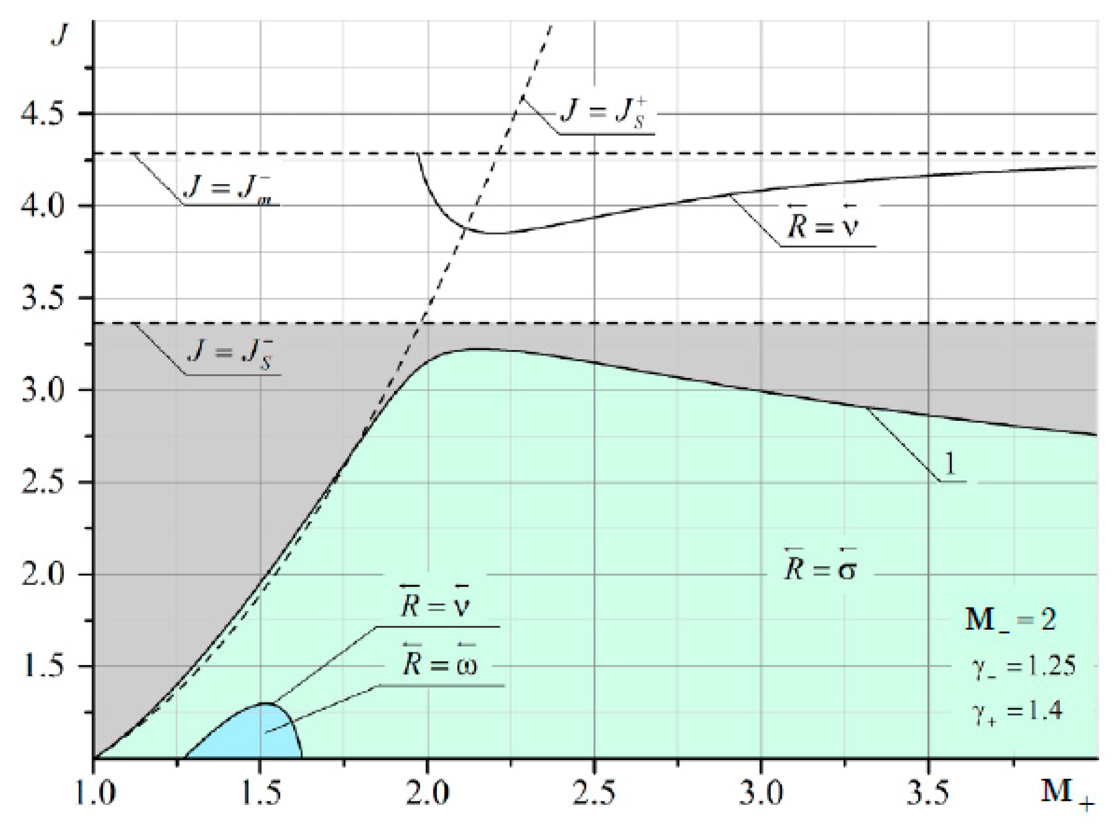
The domains of existence of reflected discontinuities for refraction from a gas consisting of combustion products into a diatomic gas at the Mach number of the flow M– = 2 are shown in Figure A1.
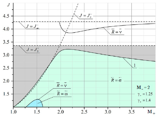
Figure A1.
Domains of existence of reflected discontinuities for refraction from a gas consisting of combustion products into a diatomic gas. The Mach number of the flow from which the shock comes is M– = 2.
Figure A1.
Domains of existence of reflected discontinuities for refraction from a gas consisting of combustion products into a diatomic gas. The Mach number of the flow from which the shock comes is M– = 2.
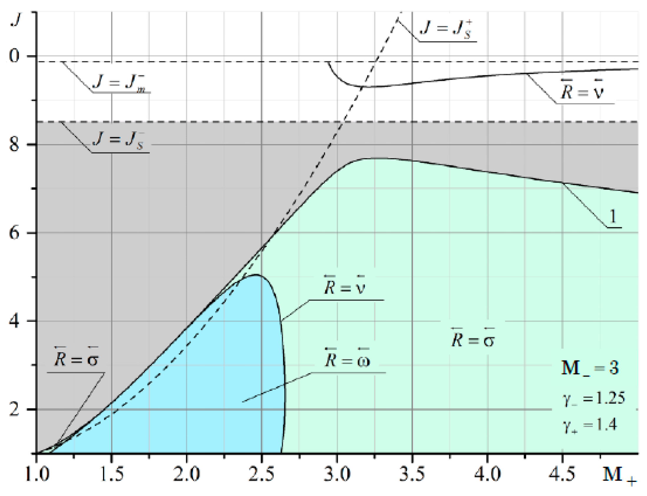
The domains of existence of reflected discontinuities for refraction from a gas consisting of combustion products into a diatomic gas at the Mach number of the flow M– = 3 are shown in Figure A2.
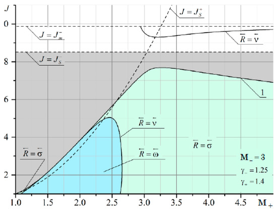
Figure A2.
Domains of existence of reflected discontinuities for refraction from a gas consisting of combustion products into a diatomic gas. The Mach number of the flow from which the shock comes is M– = 3.
Figure A2.
Domains of existence of reflected discontinuities for refraction from a gas consisting of combustion products into a diatomic gas. The Mach number of the flow from which the shock comes is M– = 3.
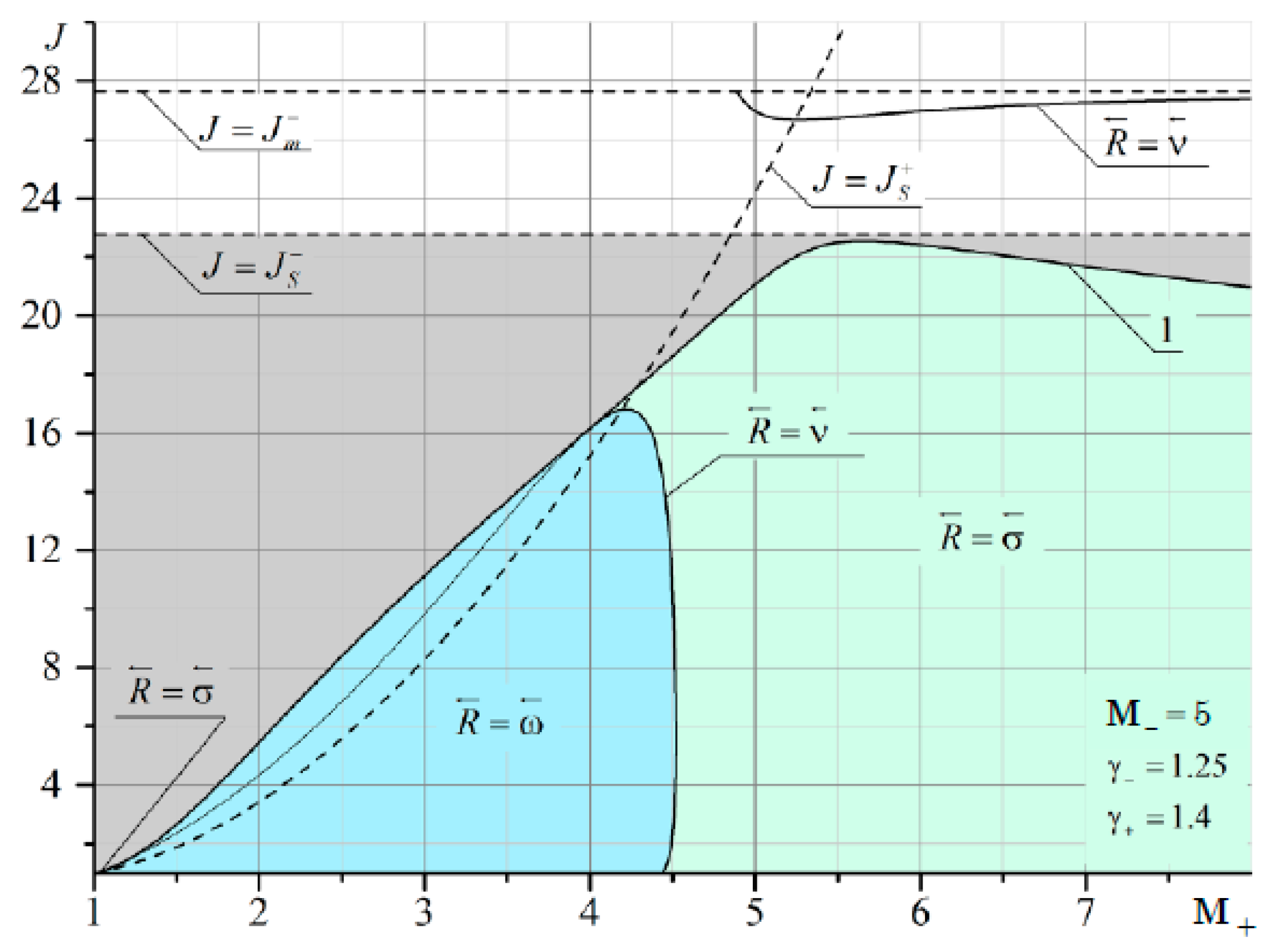
The domains of existence of reflected discontinuities for refraction from a gas consisting of combustion products into a diatomic gas at the Mach number of the flow M– = 5 are shown in Figure A3.
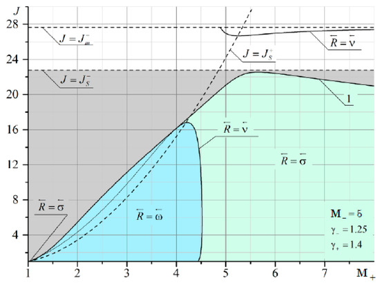
Figure A3.
Domains of existence of reflected discontinuities for refraction from a gas consisting of combustion products into a diatomic gas. The Mach number of the flow from which the shock comes is M– = 5.
Figure A3.
Domains of existence of reflected discontinuities for refraction from a gas consisting of combustion products into a diatomic gas. The Mach number of the flow from which the shock comes is M– = 5.
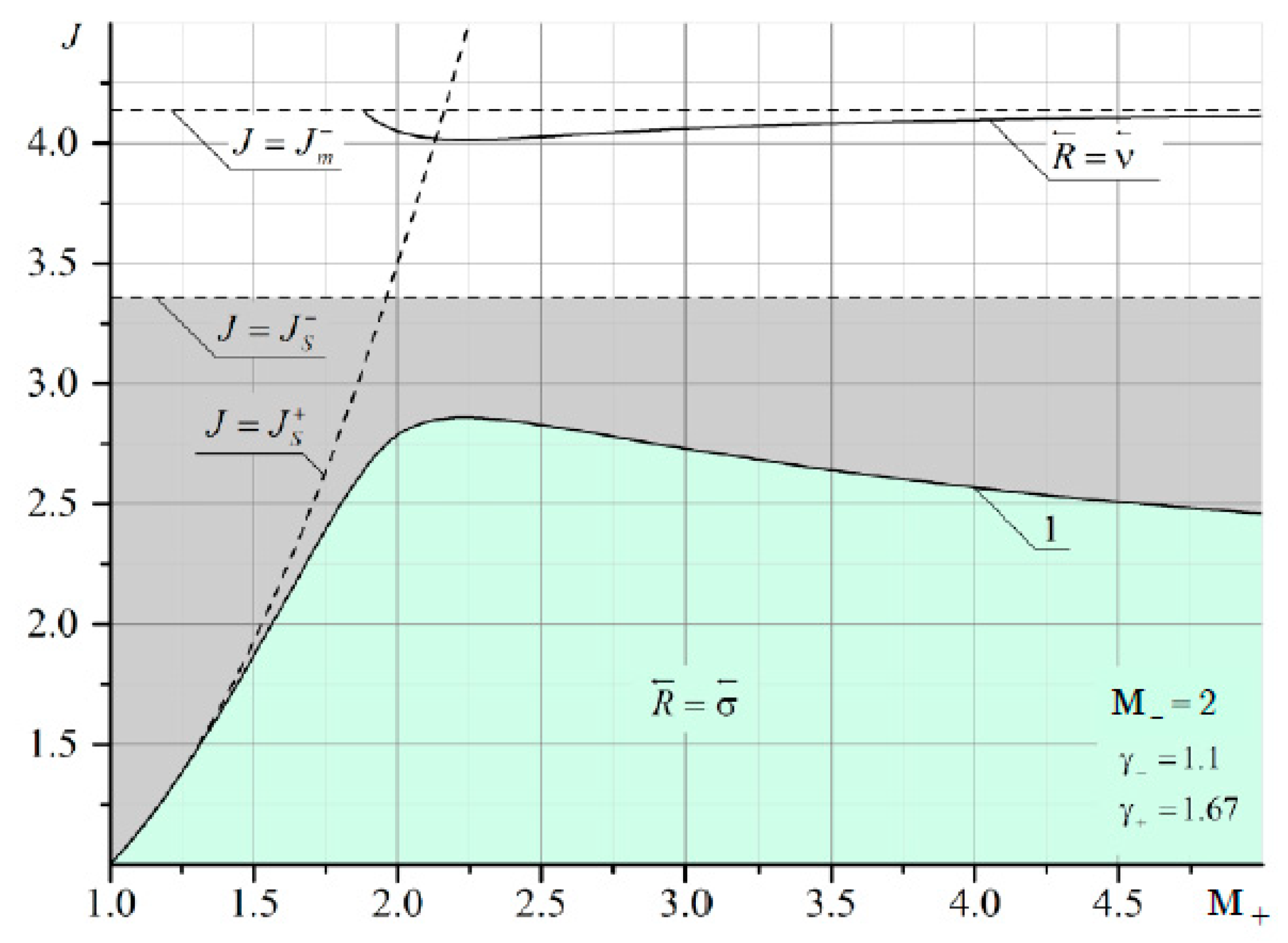
The domains of existence of reflected discontinuities for refraction from a gas consisting of combustion products into a monatomic gas at the Mach number of the flow M– = 2 are shown in Figure A4.
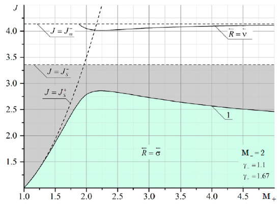
Figure A4.
Domains of existence of reflected discontinuities for refraction from a gas consisting of combustion products into a monatomic gas. The Mach number of the flow from which the shock comes is M– = 2.
Figure A4.
Domains of existence of reflected discontinuities for refraction from a gas consisting of combustion products into a monatomic gas. The Mach number of the flow from which the shock comes is M– = 2.
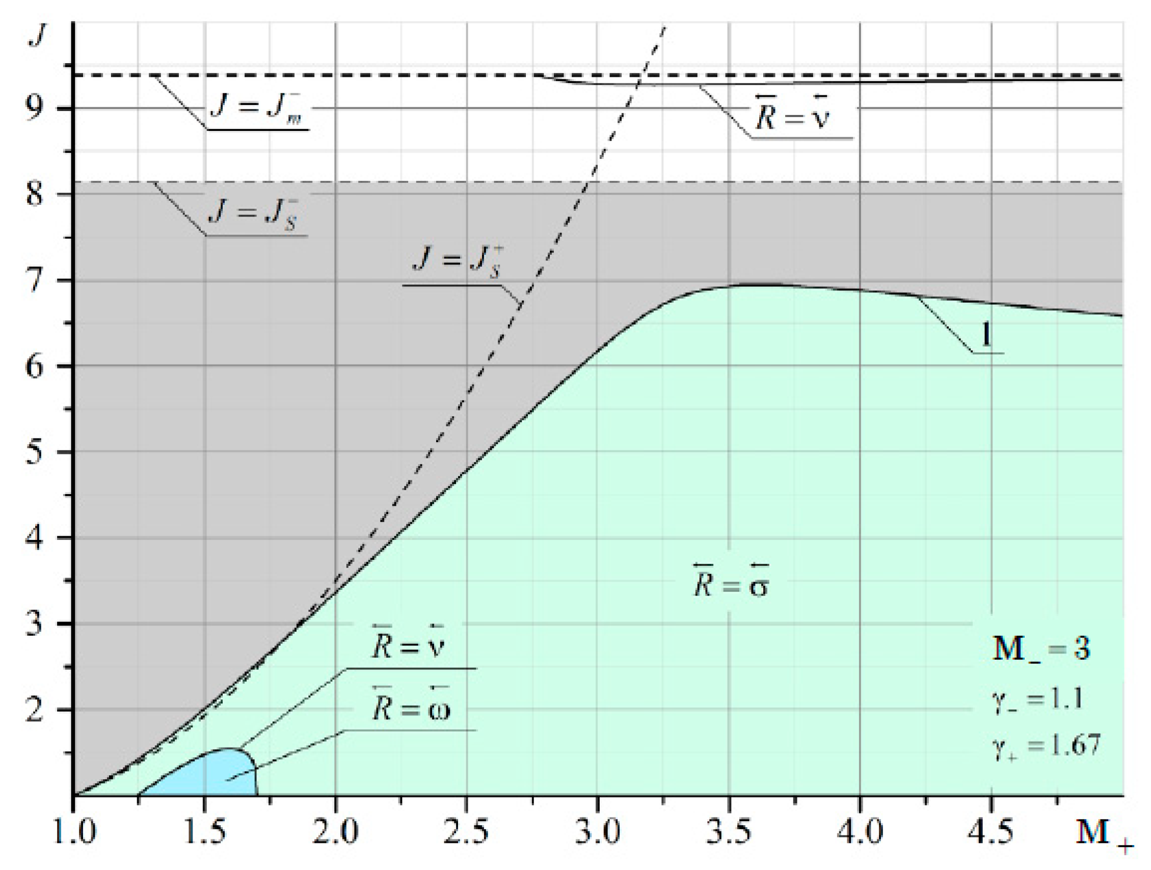
The domains of existence of reflected discontinuities for refraction from a gas consisting of combustion products into a monatomic gas at the Mach number of the flow M– = 3 are shown in Figure A5.
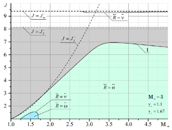
Figure A5.
Domains of existence of reflected discontinuities for refraction from a gas consisting of combustion products into a monatomic gas. The Mach number of the flow from which the shock comes is M– = 3.
Figure A5.
Domains of existence of reflected discontinuities for refraction from a gas consisting of combustion products into a monatomic gas. The Mach number of the flow from which the shock comes is M– = 3.
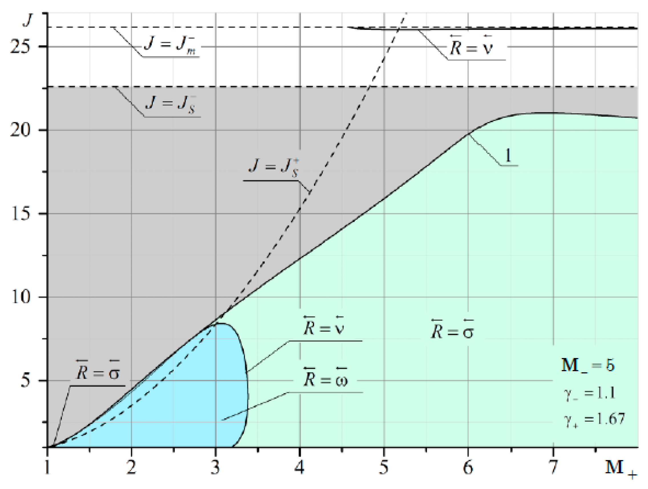
The domains of existence of reflected discontinuities for refraction from a gas consisting of combustion products into a monatomic gas at the Mach number of the flow M– = 5 are shown in Figure A6.
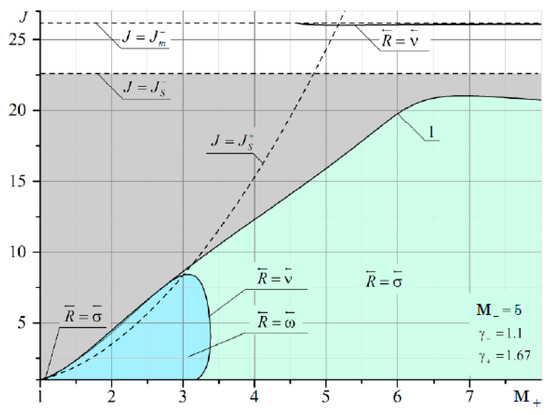
Figure A6.
Domains of existence of reflected discontinuities for refraction from a gas consisting of combustion products into a monatomic gas. The Mach number of the flow from which the shock comes is M– = 5.
Figure A6.
Domains of existence of reflected discontinuities for refraction from a gas consisting of combustion products into a monatomic gas. The Mach number of the flow from which the shock comes is M– = 5.
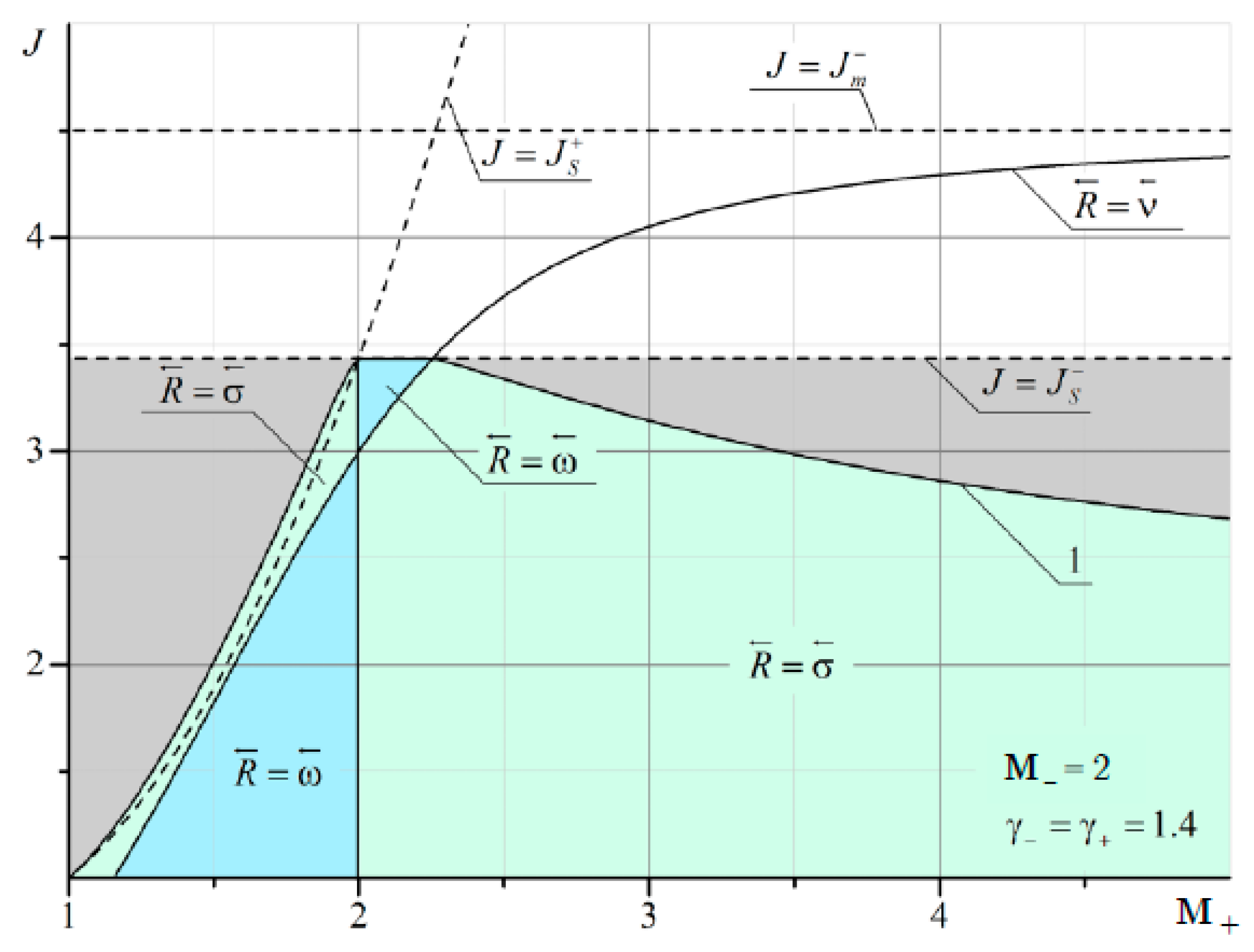
The domains of existence of reflected discontinuities for refraction in a flow of diatomic gas at the Mach number of the flow M– = 2 are shown in Figure A7.
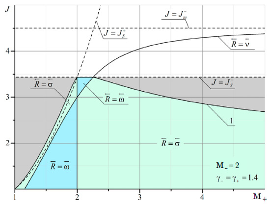
Figure A7.
Domains of existence of reflected discontinuities for refraction in a flow of diatomic gas. The Mach number of the flow from which the shock comes is M– = 2.
Figure A7.
Domains of existence of reflected discontinuities for refraction in a flow of diatomic gas. The Mach number of the flow from which the shock comes is M– = 2.
The domains of existence of reflected discontinuities for refraction in a flow of diatomic gas at the Mach number of the flow M– = 3 are shown in Figure A8.
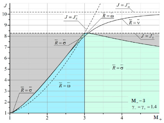
Figure A8.
Domains of existence of reflected discontinuities for refraction in a flow of diatomic gas. The Mach number of the flow from which the shock comes is M– = 3.
Figure A8.
Domains of existence of reflected discontinuities for refraction in a flow of diatomic gas. The Mach number of the flow from which the shock comes is M– = 3.
The domains of existence of reflected discontinuities for refraction in a flow of diatomic gas at the Mach number of the flow M– = 5 are shown in Figure A9.
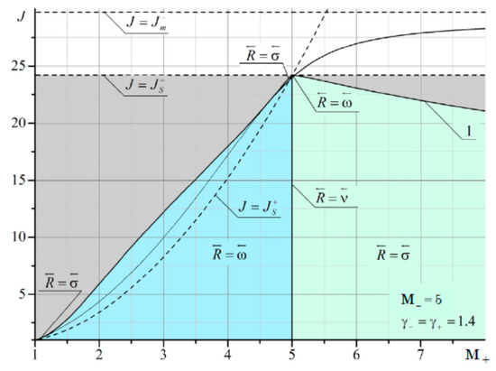
Figure A9.
Domains of existence of reflected discontinuities for refraction in a flow of diatomic gas. The Mach number of the flow from which the shock comes is M– = 5.
Figure A9.
Domains of existence of reflected discontinuities for refraction in a flow of diatomic gas. The Mach number of the flow from which the shock comes is M– = 5.
The domains of existence of reflected discontinuities for refraction from a monatomic gas into a gas consisting of combustion products at the Mach number of the flow M– = 2 are shown in Figure A10.
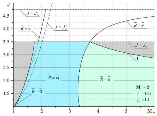
Figure A10.
Domains of existence of reflected discontinuities for refraction from a monatomic gas into a gas consisting of combustion products. The Mach number of the flow from which the shock comes is M– = 2.
Figure A10.
Domains of existence of reflected discontinuities for refraction from a monatomic gas into a gas consisting of combustion products. The Mach number of the flow from which the shock comes is M– = 2.
The domains of existence of reflected discontinuities for refraction from a monatomic gas into a gas consisting of combustion products at the Mach number of the flow M– = 3 are shown in Figure A11.
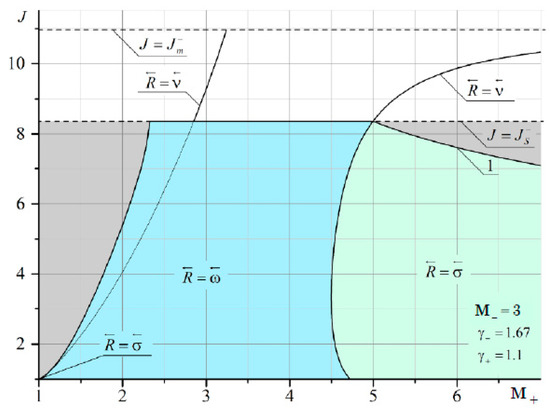
Figure A11.
Domains of existence of reflected discontinuities for refraction from a monatomic gas into a gas consisting of combustion products. The Mach number of the flow from which the shock comes is M– = 3.
Figure A11.
Domains of existence of reflected discontinuities for refraction from a monatomic gas into a gas consisting of combustion products. The Mach number of the flow from which the shock comes is M– = 3.
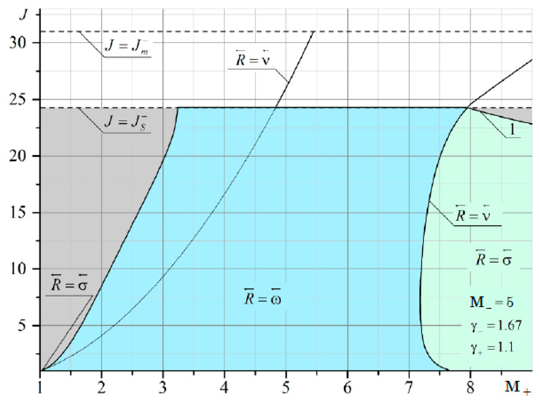
The domains of existence of reflected discontinuities for refraction from a monatomic gas into a gas consisting of combustion products at the Mach number of the flow M– = 5 are shown in Figure A12.
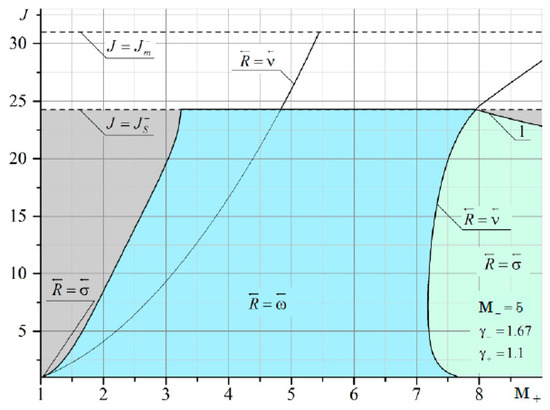
Figure A12.
Domains of existence of reflected discontinuities for refraction from a monatomic gas into a gas consisting of combustion products. The Mach number of the flow from which the shock comes is M– = 5.
Figure A12.
Domains of existence of reflected discontinuities for refraction from a monatomic gas into a gas consisting of combustion products. The Mach number of the flow from which the shock comes is M– = 5.
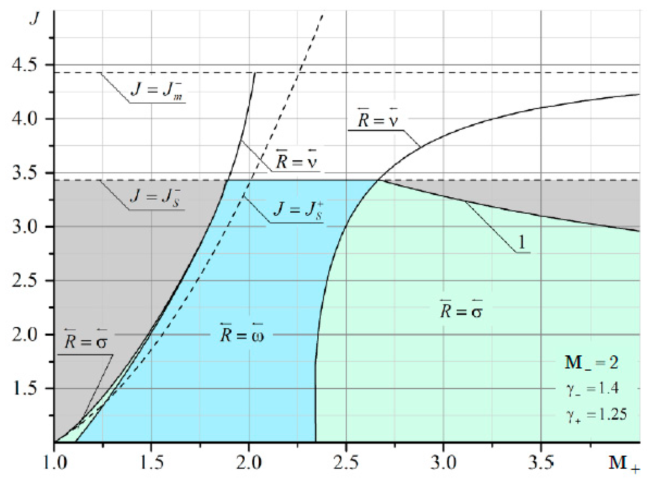
The domains of existence of reflected discontinuities for refraction from a diatomic gas into a gas consisting of combustion products at the Mach number of the flow M– = 2 are shown in Figure A13.
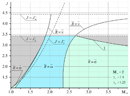
Figure A13.
Domains of existence of reflected discontinuities for refraction from a diatomic gas into a gas consisting of combustion products. The Mach number of the flow from which the shock comes is M– = 2.
Figure A13.
Domains of existence of reflected discontinuities for refraction from a diatomic gas into a gas consisting of combustion products. The Mach number of the flow from which the shock comes is M– = 2.
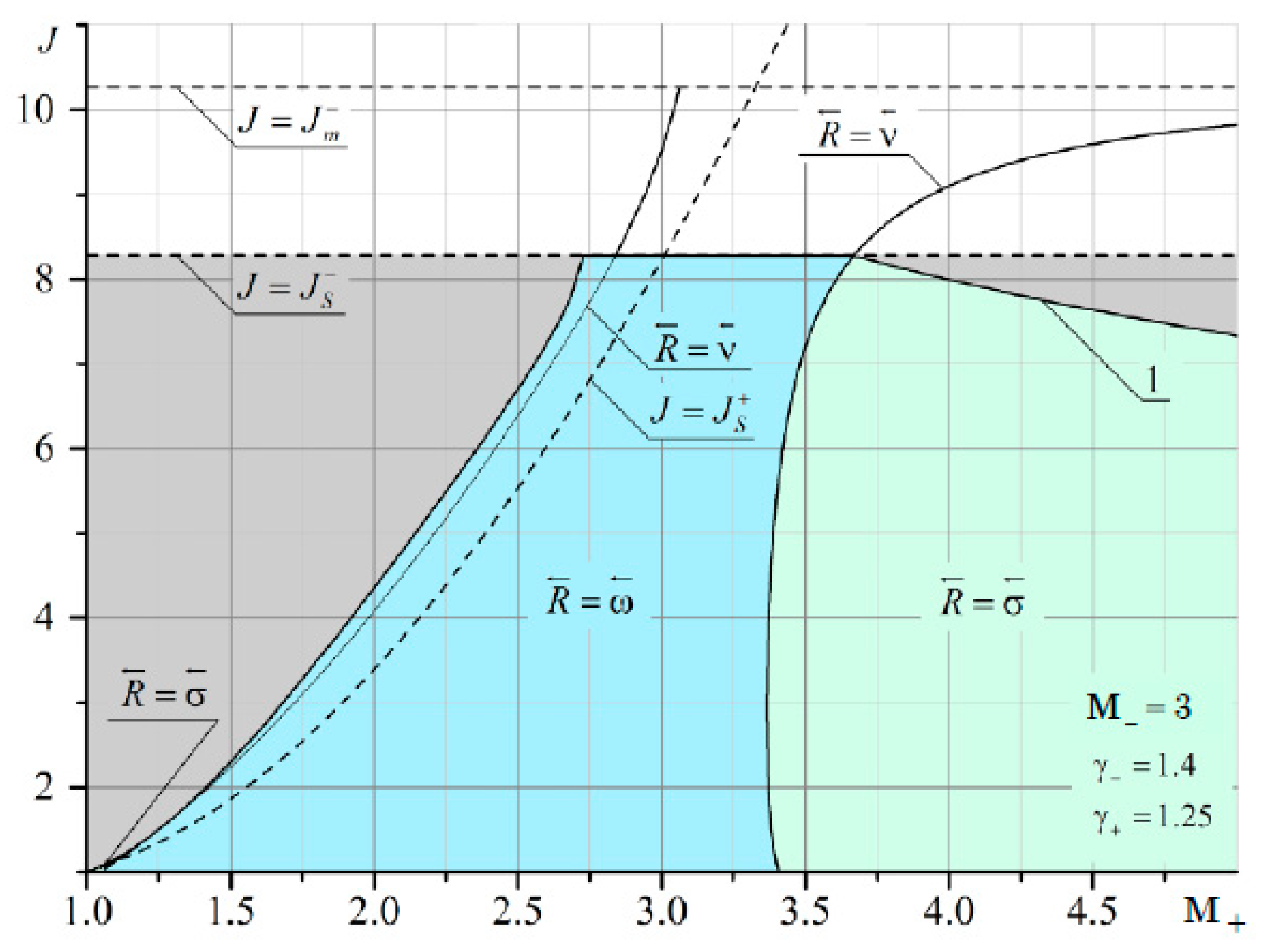
The domains of existence of reflected discontinuities for refraction from a diatomic gas into a gas consisting of combustion products at the Mach number of the flow M– = 3 are shown in Figure A14.
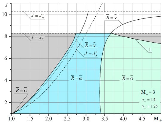
Figure A14.
Domains of existence of reflected discontinuities for refraction from a diatomic gas into a gas consisting of combustion products. The Mach number of the flow from which the shock comes is M– = 3.
Figure A14.
Domains of existence of reflected discontinuities for refraction from a diatomic gas into a gas consisting of combustion products. The Mach number of the flow from which the shock comes is M– = 3.
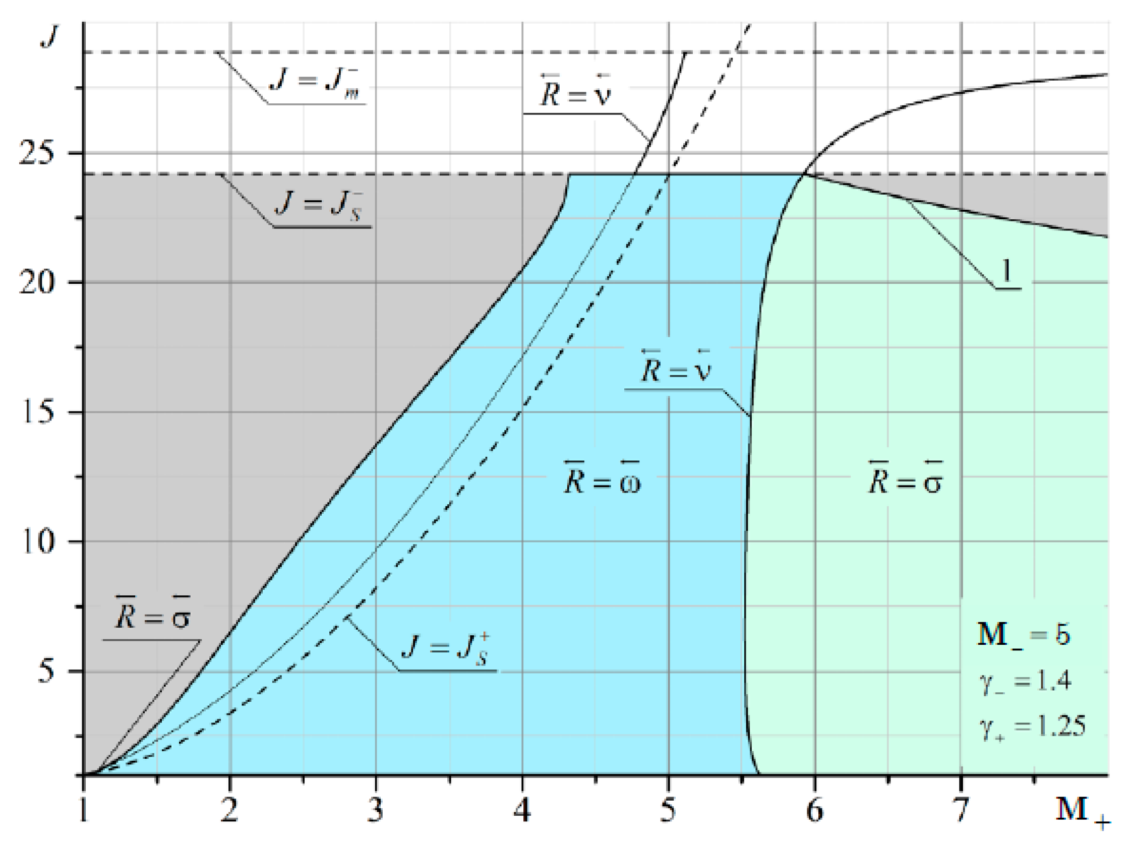
The domains of existence of reflected discontinuities for refraction from a diatomic gas into a gas consisting of combustion products at the Mach number of the flow M– = 5 are shown in Figure A15.
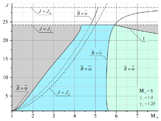
Figure A15.
Domains of existence of reflected discontinuities for refraction from a diatomic gas into a gas consisting of combustion products. The Mach number of the flow from which the shock comes is M– = 5.
Figure A15.
Domains of existence of reflected discontinuities for refraction from a diatomic gas into a gas consisting of combustion products. The Mach number of the flow from which the shock comes is M– = 5.
The domains of existence of reflected discontinuities for refraction from a hydrogen/oxygen mixture at Mach number M– = 3.27 corresponding to Chapman–Judge detonation are shown in Figure A16.
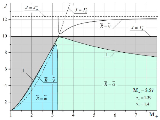
Figure A16.
Domains of existence of reflected discontinuities for refraction from a hydrogen/oxygen mixture at Mach number M– = 3.27 corresponding to Chapman–Judge detonation.
Figure A16.
Domains of existence of reflected discontinuities for refraction from a hydrogen/oxygen mixture at Mach number M– = 3.27 corresponding to Chapman–Judge detonation.
The domains of existence of reflected discontinuities for refraction from a propane/air/combustion product mixture at Mach number M– = 5.46 corresponding to Chapman–Judge detonation are shown in Figure A17.
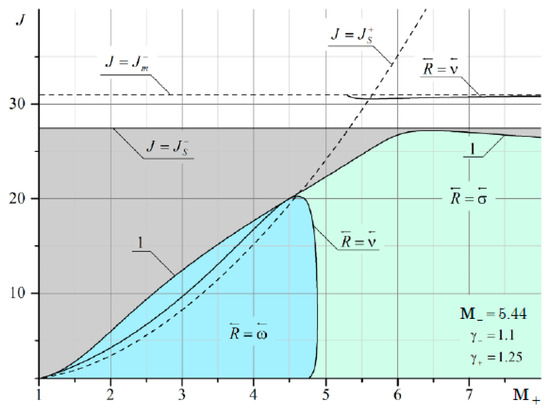
Figure A17.
Domains of existence of reflected discontinuities for refraction from a propane/air/combustion product mixture at Mach number M– = 5.46 corresponding to Chapman–Judge detonation.
Figure A17.
Domains of existence of reflected discontinuities for refraction from a propane/air/combustion product mixture at Mach number M– = 5.46 corresponding to Chapman–Judge detonation.
References
- Adrianov, A.L.; Starykh, A.L.; Uskov, V.N. Interference of Steady Gas Dynamic Discontinuities; Nauka: Novosibirsk, Russia, 1995. [Google Scholar]
- John, R.G. The refraction of shock waves at a gaseous interface. J. Fluid Mech. 1956, 1, 457–489. [Google Scholar] [CrossRef]
- Zeng, S.; Takayama, K. On the refraction of shock wave over a slow-fast gas interface. Acta Astronaut. 1996, 38, 829–838. [Google Scholar] [CrossRef]
- Starykh, A.L. Irregular interaction of shock waves between themselves and tangential discontinuities. Numer. Methods Contin. Mech. 1986, 7, 119–124. [Google Scholar]
- Uskov, V.N. Interference of gas dynamics and tangential discontinuities. Fluids Dyn. 1979, 4, 191–197. [Google Scholar]
- Abd-El-Fattah, A.M.; Henderson, L.F. Shock waves at a fast-slow gas interface. J. Fluid Mech. 1978, 86, 15–32. [Google Scholar] [CrossRef]
- Abd-El-Fattah, A.M.; Henderson, L.F. Shock waves at a slow-fast gas interface. J. Fluid Mech. 1978, 89, 79–95. [Google Scholar] [CrossRef]
- Henderson, L.F.; Colella, P.; Puckett, E.G. On the refraction of shock waves at a slow-fast gas interface. J. Fluid Mech. 1991, 224, 1–27. [Google Scholar] [CrossRef]
- Uskov, V.N.; Starykh, A.L. Analysis of the region of existence of stationary gas dynamic discontinuities equation solution. In Unsteady Gas Flows and Shock Waves; St. Petersburg State University: St. Petersburg, Russia, 1990; pp. 359–372. [Google Scholar]
- Nouragliev, R.R.; Sushchikh, S.Y.; Dinh, T.N.; Theofanous, T.G. Shock wave refraction patterns at interfaces. Int. J. Multiph. Flow 2005, 31, 969–995. [Google Scholar] [CrossRef]
- Henderson, L.F. On the refraction of shock waves. J. Fluid Mech. 1989, 198, 365–386. [Google Scholar] [CrossRef]
- Samtaney, R.; Zabusky, N.J. On shock polar analysis and analytical expressions for vorticity deposition in shock-accelerated density stratified interfaces. Phys. Fluids 1993, 5, 1285–1287. [Google Scholar] [CrossRef]
- Samtaney, R.; Pullin, D.I. On initial-value and self-similar solutions of the compressible Euler equations. Phys. Fluids 1996, 8, 2650–2655. [Google Scholar] [CrossRef][Green Version]
- Samtaney, R. Suppression of the Richtmyer–Meshkov instability in the presence of a magnetic field. Phys. Fluids 2003, 15, L53–L56. [Google Scholar] [CrossRef]
- Wheatley, V.; Pullin, D.I.; Samtaney, R. Regular shock refraction at an oblique planar density interface in magnetohydrodynamics. J. Fluid Mech. 2005, 522, 179–214. [Google Scholar] [CrossRef]
- Yang, X.; Chern, I.; Zabusky, N.J.; Samtaney, R.; Hawley, J.F. Vorticity generation and evolution in shock-accelerated density-stratified interfaces. Phys. Fluids 1992, 4, 1531–1540. [Google Scholar] [CrossRef]
- Delmont, P.; Keppens, R.; van der Holst, B. An exact Riemann solver based solution for regular shock refraction. J. Fluid Mech. 2009, 627, 33–53. [Google Scholar] [CrossRef]
- Pember, R.B.; Anderson, R.W. Comparison of direct Eulerian Godunov and Lagrange plus remap, artificial viscosity schemes. AIAA Paper 2001, 2001–2644. [Google Scholar] [CrossRef]
- Samtaney, R.; Meiron, D.I. Hypervelocity Richtmyer–Meshkov instability. Phys. Fluids 1997, 9, 1783–1803. [Google Scholar] [CrossRef]
- Banuti, D.T.; Grabe, M.; Hannemann, K. Steady shock refraction in hypersonic ramp flow. AIAA Paper 2011, 2011–2215. [Google Scholar] [CrossRef]
- Brouillette, M. The Richtmyer–Meshkov instability. Annu. Rev. Fluid Mech. 2002, 34, 445–468. [Google Scholar] [CrossRef]
- Dutta, S.; Glimm, J.; Grove, J.W.; Sharp, D.H.; Zhang, Y. Error comparison in tracked and untracked spherical simulations. Comput. Math. Appl. 2004, 48, 1733–1747. [Google Scholar] [CrossRef][Green Version]
- Liu, T.C.; Khoo, B.C.; Yeo, K.S. The simulation of compressible multi-medium flow. I. A new methodology with test applications to 1D gas–gas and gas–water cases. Comput. Fluids 2001, 30, 291–314. [Google Scholar] [CrossRef]
- Liu, T.C.; Khoo, B.C.; Yeo, K.S. The simulation of compressible multi-medium flow. II. Applications to 2D underwater shock refraction. Comput. Fluids 2001, 30, 315–337. [Google Scholar] [CrossRef]
- Silnikov, M.V.; Chernyshov, M.V.; Uskov, V.N. Analytical solutions for Prandtl-Meyer wave—Oblique shock overtaking interaction. Acta Astronaut. 2014, 99, 175–183. [Google Scholar] [CrossRef]
- Shoev, G.V.; Ivanov, M.S. Numerical study of shock wave interaction in steady flows of a viscous heat-conducting gas with a low ratio of specific heats. Thermophys. Aeromech. 2016, 23, 343–364. [Google Scholar] [CrossRef]
- Gounko, Y.P. Patterns of steady axisymmetric supersonic compression flows with a Mach disk. Shock Waves 2017, 27, 495–506. [Google Scholar] [CrossRef][Green Version]
- Vasilev, E.I. The nature of the triple point singularity in the case of stationary reflection of weak shock waves. Fluid Dyn. 2016, 51, 804–813. [Google Scholar] [CrossRef]
- Bai, C.-Y.; Wu, Z.-N. Size and shape of shock waves and slip line for Mach reflection in steady flow. J. Fluid Mech. 2017, 818, 116–140. [Google Scholar] [CrossRef]
- Roy, S.; Gopalapillai, R. An analytical model for asymmetric Mach reflection configuration in steady flows. J. Fluid Mech. 2019, 863, 242–268. [Google Scholar] [CrossRef]
- Lin, J.; Bai, C.-Y.; Wu, Z.-N. Study of asymmetrical shock wave reflection in steady supersonic flow. J. Fluid Mech. 2019, 864, 848–875. [Google Scholar] [CrossRef]
- Chen, S.; Fang, B. Stability of reflection and refraction of shocks on interface. J. Differ. Equ. 2008, 244, 1946–1984. [Google Scholar] [CrossRef][Green Version]
- Chen, S.; Hu, D.; Fang, B. Stability of the E–H type regular shock refraction. J. Differ. Equ. 2013, 254, 3146–3199. [Google Scholar] [CrossRef]
- Martínez-Ruiz, D.; Huete, C.; Martínez-Ferrer, P.J.; Mira, D. Irregular self-similar configurations of shock-wave impingement on shear layers. J. Fluid Mech. 2019, 872, 889–927. [Google Scholar] [CrossRef]
- Chernyshov, M.V.; Murzina, K.E.; Matveev, S.A.; Yakovlev, V.V. Shock-wave structures of prospective combined ramjet engine. IOP Conf. Ser. Mater. Sci. Eng. 2019, 618, 012068. [Google Scholar] [CrossRef]
- Alekseeva, M.M.; Matveev, S.A.; Savelova, K.E.; Chernyshov, M.V. Interaction of steady gas-dynamic discontinuities and waves on supersonic gas jet flows from rocket engines. AIP Conf. Proc. 2021, 2318, 06000. [Google Scholar]
Publisher’s Note: MDPI stays neutral with regard to jurisdictional claims in published maps and institutional affiliations. |
© 2021 by the authors. Licensee MDPI, Basel, Switzerland. This article is an open access article distributed under the terms and conditions of the Creative Commons Attribution (CC BY) license (https://creativecommons.org/licenses/by/4.0/).

