Abstract
A numerical simulation of the gas-dynamic processes in the thrust vectorable nozzle of the solid rocket motor is considered. Construction of a geometric model and a generation of computational mesh, and reconstruction of model and mesh at each time step are discussed. Calculations of the flowfield of combustion products in the pre-nozzle chamber and nozzle block are carried out for various angles of nozzle rotation. The distributions of the gas dynamic quantities in the pre-nozzle volume corresponding to the outflow of the combustion products from the cylindrical channel and star-shaped channel are compared, as well as the solutions of the problem obtained with quasi-stationary and unsteady formulations. The effects of the channel shape on the distribution of flow quantities and formation of a vortical flow structure in the nozzle block are discussed.
1. Introduction
One of the ways to improve the efficiency of solid propellant rocket motors (SRM) is the use of reliable control [1]. To create control moments in the design of SRMs, rotary vectorable nozzles (thrust vectorable nozzle) are used, which are deflected by the steering drives at the commands of the flight control system [2]. Common issues related to the design of thrust nozzles and calculations of fluid flows are discussed in [3,4,5,6].
The control forces in the rotary nozzles are created by rotating the jet of combustion products together with the nozzle. The presence of an angle between the centreline of the rocket and the direction of the thrust vector gives rise to a moment relative to the center of mass of the rocket. The main advantages of rotary vectorable nozzles are the absence of mechanical action on the gas jet (low thrust and specific impulse losses), linear dependence of the control force on the nozzle rotation angle, stability of the main characteristics during SRM operation, and relative simplicity of the design. The main disadvantages of rotary nozzles include the harsh operating conditions of the rotation unit loaded with high pressure of combustion products containing a condensed phase and having a high temperature, as well as a large frictional moment in the joints and in the rotary units.
For technological reasons, the subsonic part of the rotary nozzle is usually submerged into the combustion chamber (submerged nozzle). The immersion of the nozzle inside the pre-nozzle volume reduces the longitudinal size of the rocket, but generates a number of problems associated with the high-temperature flow of combustion products [7,8,9]. In a submerged nozzle, the impact of a two-phase flow of combustion products hits the frontal surface of the nozzle inlet, which poses the problem of organizing the flow in this area, excluding increased thermal and erosion effects [2]. The gas-dynamic in the pre-nozzle volume is complicated by the variety of forms of charges used (round channels, star-shaped channels, and others) [2].
The formation of longitudinal large-scale vortices near the nozzle wall in its supersonic part and the possibility of using porous inserts for passive control of the nozzle thrust are considered in [10]. The size of the vortex structures exceeds the thickness of the boundary layer and depends on the parameters of the gas injected through the wall. Large-scale longitudinal paired vortices rotating in opposite directions are observed when plane and round subsonic jets flow onto a recessed nozzle [11]. The vortices are formed in the subsonic part of the nozzle, and then are carried out into its supersonic part, where their intensity decreases due to the expansion of the vortex tubes. The formation of vortices is associated with the curvature of streamlines arising when the jet flows onto the subsonic part of the nozzle [10].
The operation of a SRM with a rotary vectorable nozzle is associated with an asymmetric gas flow along the path of the combustion chamber and the nozzle, which results in a lateral force and a gas-dynamic moment acting on the nozzle. A complex three-dimensional gas flow is characterized by the presence of attachment and detachment lines, the formation of vortex structures, as well as separation zones leading to the enhancement of heat transfer; asymmetric entrainment of material, and uneven deposition of condensed phase particles on the nozzle walls [2]. Complex shapes of propellant channel gives rise to a variety of different flow structures [12,13], leading, in particular, to the emergence of secondary, tertiary and multi-branched flows. The flow near the nozzle bottom is characterized by the presence of gas-dynamic features (zones of stagnation and flow reversal, areas with high pressure gradients) [14,15].
The data of the physical experiment [2] show that there are two flow regimes around the recessed nozzle, the regime with the displacement of the channel flow from the nozzle surface (regime 1) and the regime with the penetration of the channel flow to the surface of the recessed nozzle (regime 2). In regime 1, the entire surface of the nozzle is washed by the flow coming from the over-nozzle part of the charge. In regime 2, the flow coming from the charge channel partially displaces the nozzle flow and reaches the nozzle surface, forming localized areas with points and zones of stagnation. The nozzle flow enters the nozzle in the intervals between the channel flow connection zones. The implementation of one or another flow regime depends on the ratio between the velocity heads of flows from the supra-nozzle and from the channel parts of the charge (the flow regime changes when a certain critical value is exceeded). The flow regimes around a recessed nozzle are characterized by different levels of thermal interaction of the gas with the nozzle surface, and also determine the qualitative features of the transfer of particles of the condensed phase [12,16].
To calculate the characteristics of the flow over the submerged part of the nozzle (between the burning surface of the charge and the submerged inlet part of the nozzle) at the initial time of SRM operation, a flow model in an annular cylindrical channel with permeable walls is used [2,12]. As the fuel burns out, the channel diameter and the annular gap above the recessed part of the nozzle increase. In this case, the velocity head of the main flow in the channel exceeds the velocity head of the counter flow from the annular gap, and the flow pattern over the submerged part of the nozzle changes. The violation of symmetry is accompanied by asymmetric flow from the channel into the annular region and spatial flow around the nozzle cover [1].
In [17], the existence of hysteresis phenomena in planar symmetric and rotated nozzles caused by the Coanda effect, as well as the interaction of the boundary layer with the in-nozzle shock wave on the supersonic nozzle flaps, is discovered in the overexpansion mode. Hysteresis phenomena give a discrepancy of up to 4% in the thrust coefficient for the same parameters of the problem.
The flow around a submerged nozzle with a stream containing condensed combustion products is modeled in [18,19]. The results obtained allow to calculate the carryover of the heat-shielding coating of the nozzle. Two-phase flows in the trapped cavity are studied in [20]. Modeling of large eddies of turbulent flow in a cavity, which is used as a model of the gap between the engine casing and the recessed part of the nozzle, is carried out in [21]. The flows in sliding nozzles are modeled in [22].
This study focuses on the calculations of the flowfield of combustion products in the propellant channel, pre-nozzle volume and nozzle block. Computational fluid dynamics (CFD) simulations are carried out for different angles of rotation of the vectorable nozzle. To simulate the rotation of the nozzle, an approach is developed based on the explicit specification of the motion of the vertices of the mesh structure. Design of a geometric model and a generation of computational mesh are discussed. CFD results are presented for different angles of rotation of the nozzle and various shapes of propellant channel, and the formation of the vortex flow pattern in the pre-nozzle volume is discussed.
2. Geometrical Model
The presence of symmetry at zero angles of rotation of the nozzle makes it possible to investigate the initial state of the structure on the basis of the model developed for calculating the flows in the channels of SRM [2,12]. Such a model is of interest at the initial stage of the SRM operation when simulating the nozzle start-up processes, as well as at the final stages of its operation when simulating the thrust cutoff. When studying the processes that arise during the processing of commands of the control system, the symmetry of the computational domain disappears, which leads to the need to create a parametric geometric model, to describe the deformation law of the computational domain, and to rearrange the mesh structure at each time step.
The geometric model of the axisymmetric nozzle block is shown in Figure 1 (lengths are given in millimeters). The model is a body of rotation consisting of a set of three-dimensional primitives (cube, sphere, cylinder, and others), interconnected according to a certain law using logical operations.
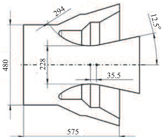
Figure 1.
Geometrical model.
The main difficulty in constructing a geometric model lies in the fact that the nozzle block rotates by a certain angle relative to a certain point (the nozzle rotation angle varies from −10° to +10°). The solid model is constructed taking into account the fact that the turning point is located both in the subcritical and supercritical parts of the nozzle, and when the moving part of the nozzle block is rotated, one of the surfaces changes its shape, thereby preventing surface rupture. The structural element before and after turning the nozzle through an angle of 6° is shown in Figure 2.
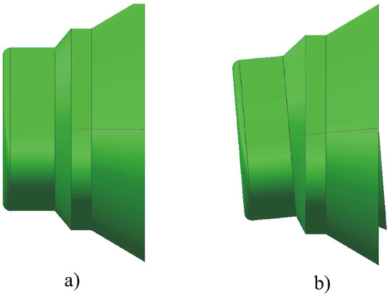
Figure 2.
Nozzle block before (a) and after (b) rotation.
The channels of the solid propellant have a different geometric design associated with the need to ensure a given rate of solid fuel combustion. The implementation of a solid model allows to combine nozzles and channels with different cross-sectional shapes in the plan. Specific implementations are built for channels with a circular and star-shaped (4 beams) cross-sectional shapes in plan.
3. Computational Mesh
Modern SRMs have a rather complex internal structure of flow propellant channels. To design a block-structured mesh in a geometrically complex area, the physical volume is divided into a number of non-intersecting blocks, in each of which the mesh resolution is selected based on the gas-dynamic features of the flow.
The mesh on the nozzle surface and the mesh in the longitudinal section of the computational domain are shown in Figure 3 at zero angle of rotation of the nozzle (the nozzle block and part of the cylindrical channel attached to the nozzle are shown). The mesh contains about one million cells, with two-thirds of the cells in the nozzle block.
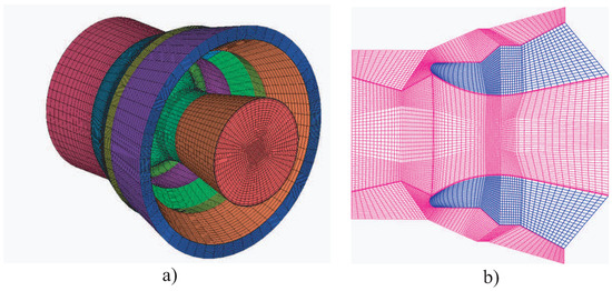
Figure 3.
Mesh in nozzle block (a) and mesh in the meridional section (b).
4. Model Rotation
To design a model of a rotary vectorable nozzle and implement an object deformation algorithm, various approaches are used—in particular, an approach based on setting the equation of motion for all points of the model, and an approach based on creating a base of model states. Both approaches have advantages and disadvantages, as well as areas of application.
The approach based on creating a base of model states include specification of the sets of coordinates of the vertices for all the required geometrical states of the object, which are stored in the form of a library of files of the geometric positions of the model. The main advantage of the approach is the accuracy of describing the change in geometry over time, since the mesh structures for all positions of the model are created on the basis of the original geometric model. For each moment in time, its own intermediate state is set, which generates a large number of files containing data on the current state. This approach significantly impoverishes the understanding of the ongoing processes. The most important positions of the system, at which extreme modes of operation are realized, due to the non-linearity of the processes, are quite difficult to find, therefore one cannot be sure of the accuracy of the estimation of the ranges of the operating parameters of the system. In this case, the effect of the deformable object on its environment is not taken into account, which is important in areas with low flow rates comparable to the deformation rate, to which the zone of the rear nozzle cover belongs. In the case of unsteady spatial flow around the nozzle block, the vortex formation process depends, among other things, on the movement of the streamlined object, which, in turn, affects the intensity of heat transfer in this area.
The description of body motion using some functional dependence (depending on one or another input parameter, for example, the angle of deflection of the nozzle from the axisymmetric position) does not impose any requirements on free disk space and allows changing the time step within wide limits. The positions of the key points of the model are recalculated depending on the specified angle of rotation of the nozzle without creating additional files on the disk. The disadvantages of this approach are an increase in the computation time (the recalculation of the position of the characteristic points and the reconstruction of the model take some time), as well as the possible uncontrollable distortion of the model during computation and the appearance of mesh defects (for example, mesh cells with a negative volume).
For simplicity, a periodic law of variation of the angle of rotation of the nozzle in time is chosen
where A is the amplitude, T is the half-period. The result is an explicit description of the position of each mesh node at any time. The mesh topology remains unchanged, and the mesh cells stretch or shrink as the computational domain is rotated.
To describe the motion of each vertex of the mesh structure, Lagrange polynomials are applied. They are constructed from several basic positions of the model (usually 3–4 basic states are used). The equation of motion of the mesh vertex with the number k is taken in the form (the mesh nodes move in a circle centered at the nozzle pivot point)
where is the coordinate of the mesh node (x, y or z), is angle of rotation of the nozzle. For a three-dimensional problem, an array is obtained containing coefficients, where N is the number of mesh nodes, and M is the number of base positions (the number of support positions is one more than the order of the Lagrange polynomial). In the calculations, the basic positions of the model correspond to the nozzle rotation angles equal to , and .
To find the coefficients A, B and C, the system of equations is solved for three given angles of rotation of the nozzle , , and the corresponding states of the system , , . The coefficients are found from the following ratios:
The indicated relations are obtained by reducing the terms to the corresponding powers in the equation
Subscripts 0, 1 and 2 correspond to the three reference geometrical states of the model. In 3D space, the coefficients A, B, and C are calculated for each of the x, y, and z coordinates, resulting in a set of Lagrange coefficients, where N is the number of vertices. The obtained coefficients are used to determine the intermediate state of the system at a given angle of rotation of the nozzle.
5. Boundary Conditions
The conditional combustion products of some solid fuel with a density g/cm3 and a combustion products temperature of K are considered. The fuel combustion rate depends on the pressure in the combustion chamber according to the power law
Combustion products have the following characteristics: molecular weight is M = 0.0268 kg/mol, dynamic viscosity is Pa s, specific heat capacity at constant pressure is J/(kg K), thermal conductivity is W/(m K).
The mass flow rate (the rate of injection of combustion products through the side surface of the propellant channel) is calculated using the mass balance equation written on the mass supply surface of the channel
where F is the cross-sectional area. The subscript s refers to fuel, and the subscript g refers to combustion products.
To reduce the time required to solve unsteady problem, data transfer from one model to another (decomposition method) is used. To formulate the boundary conditions in the inlet section of the computational domain, it is decomposed into two blocks corresponding to the propellant channel and the nozzle block. The non-dimensional length of the channel is . The initial flow field (flow at zero nozzle rotation angle) is calculated over the entire area. A section of the model is selected in which the influence of disturbances created by the rotation of the nozzle is insignificant, and the parameters of the flow in this section are determined. Setting the flow quantities at the inlet to the nozzle block (density, velocity, pressure) obtained from the solution of the problem for the propellant channel makes it possible to consider the influence of the shape of the charge on the flow pattern of the nozzle block without rearranging the nozzle mesh structure. A comparison of the velocity distributions obtained on the basis of the complete and simplified approaches shows that the decomposition method leads to an error not exceeding 1% at the maximum nozzle rotation angle.
In the inlet section of the computational domain corresponding to the section of the channel with injection, the profiles of the velocity components, pressure and turbulence characteristics obtained from the calculation of the flowfield in the propellant channel with a different cross-sectional shape [12], are set. The characteristics of turbulence on the wall are found using the method of wall functions. Setting the velocity profile and other parameters of the flow at the inlet to the nozzle block makes it possible to simplify the solution of the problem, and the assumption of quasi-stationarity of the flow in the propellant channel allows not to recalculate the velocity profile in the inlet section at each time step.
6. Computational Procedure
The calculations are carried out with the Reynolds-averaged Navier–Stokes (RANS) equations and equations of standard k− turbulence model with wall functions.
Discretization of the governing equations is carried out using the finite volume method on unstructured mesh and the SIMPLE (Semi-Implicit Method for Pressure Linked Equations) pressure correction method. The upwind finite difference scheme of the 2nd order is used for discretization of inviscid flows, and a centered finite difference scheme of the second order is used for discretization of viscous flows. Time integration is carried out using an implicit scheme of the second order. The system of finite difference equations is solved with the algebraic multigrid method. To accelerate the convergence of CFD calculations, the conjugate gradient method is used.
7. Results and Discussion
CFD calculations are carried out for different angles of rotation of the nozzle and for different design options for the solid propellant channel and pre-nozzle volume.
7.1. Velocity and Pressure Distributions
The flow pattern in the propellant channel, which has a circular cross-sectional shape, and in a submerged nozzle at a zero angle of rotation is shown in Figure 4 (the injection speed is chosen as the characteristic speed). In the propellant channel, the flow remains substantially subsonic, which makes it possible to use the approximation of a viscous incompressible fluid (compressibility becomes an important in sufficiently long channels). At the outlet section of the nozzle, the Mach number is 2.1 (Figure 4a). The generation of the kinetic energy of turbulence starts at (Figure 4b), and the generation of turbulent viscosity starts at (Figure 4c).

Figure 4.
Contours of Mach number (a), turbulent kinetic energy (b) and turbulent viscosity (c).
The flowfield in the combustion chamber and submerged nozzle of a SRM is complex. The flow velocity in the propellant channel increases from the head-end leading to non-uniform profiles of streamwise velocity. Then flow undergoes transition to turbulence in the midsection of the propellant channel and becomes fully turbulent further downstream. Finally, flow velocity reaches supersonic conditions at the outlet of the nozzle. The velocity profiles and turbulence properties affect the convective heating loads and potential erosive burning of the propellant. The internal flowfield in SRM is in qualitative agreement with experimental, theoretical, and computational studies in which mean velocity and turbulent kinetic energy fields have been studied [23].
It is interesting to note that viscous effects are important in the narrow region near the channel head-end (the length of this region is inversely proportional to the Reynolds number). The flow is laminar if . Then, flow undergoes transitions to turbulence (). There is a difference in terms of turbulence generation in channel with solid walls and channel with fluid injection. In flow induced by fluid injection channel, turbulence generation is observed away from the walls. The region with maximum value of turbulent kinetic energy moves towards the wall and downstream direction () because fluid injection from the propellant surface does not allow to penetrate flow disturbances in the core region.
The locations of control sections in the nozzle block and the direction of bypassing the nozzle contour are illustrated in Figure 5. Points A and B are in the nozzle sweep plane, points C and D are in a plane rotated clockwise at an angle of to the sweep plane, and points E and F are in a plane normal to the nozzle sweep plane. The positions of the control sections are characterized by the l coordinate measured along the nozzle contour from point A.

Figure 5.
Location of control points (a) and direction along nozzle contour (b) for star-shaped channel.
In the case of a cylindrical channel and a zero angle of rotation of the nozzle, the velocity distributions in different control sections are identical (the flow is axisymmetric). For a star-shaped channel, there is not only radial, but also angular non-uniformity of the flow. The computational results are post-processed in the form of velocity distributions along the nozzle surface at control points, and they are shown in Figure 6. Both for the cylindrical and for the star-shaped channel, there is a smooth and qualitatively identical velocity distribution on the surface area up to the coordinate mm, which corresponds to the beginning of the profiled part of the nozzle. At mm, the influence of the shape of the propellant channel starts to affect, and the velocity distributions at the control points differ. The greatest differences are observed at the points corresponding to the inner diameter of the star.
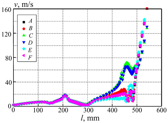
Figure 6.
Velocity distributions along nozzle surface in various control points for .
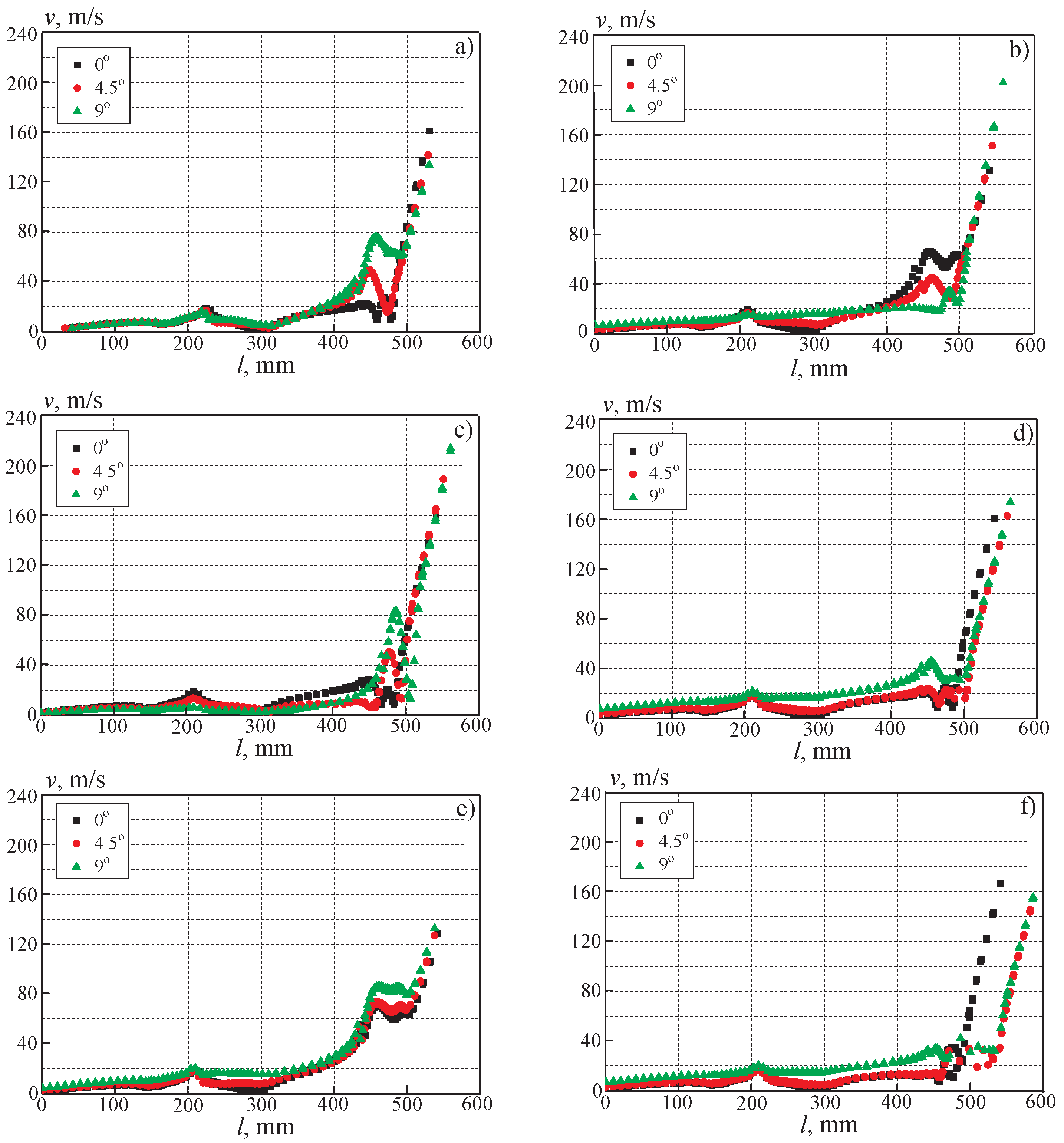
The calculation results corresponding to the unsteady solution of the problem are shown in Figure 7 for a cylindrical channel (instead of time, the angle of rotation of the nozzle is used). Figure 7a–f correspond to control points A–F, which are traversed counterclockwise. At angles of rotation of the nozzle up to 5°, the influence of the movement of the nozzle on the velocity distribution is only slightly affected, and the flow pattern differs relatively little from the state corresponding to the axisymmetric position of the nozzle. With an increase in the angle of rotation of the nozzle, the compression and expansion of the combustion products have a significant effect on the flow structure. As the width of the gap between the nozzle and the body decreases, the flow accelerates, which leads to a sufficiently large velocity drop from an almost inhibited flow at point B to the maximum velocity in the considered region at point A (when the coordinate l changes from 470 to 520 mm).
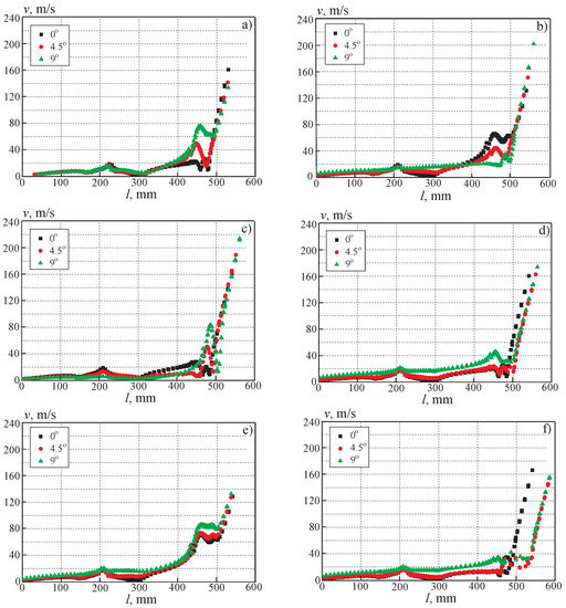
Figure 7.
Velocity distributions along nozzle surface in control points A–F (a–f) for various angles of nozzle rotation for cylindrical channel.
When the combustion products outflow from the star-shaped propellant channel and the nozzle rotation angle is zero, the velocity distributions corresponding to the interbeam sections coincide (the flow is axisymmetric). Despite the fact that with a change in the angle of rotation of the nozzle, the distribution of the velocity undergoes significant changes associated with the influence of the shape of the propellant channel, the minimum and maximum values of the velocity correspond to those observed in the cylindrical propellant channel. The complication of the shape of the charge leads to stratification of the velocity distributions when the width of the gap between the external and internal contours of the nozzle changes. The stratification of the velocity distributions along the recessed part of the nozzle also occurs at a zero angle of rotation of the nozzle, which is associated with the difference in the flow quantities in the planes along the beams of the star and in the planes between the beams. The shape and location of the arch of the over-nozzle surface of the charge have a significant effect on the velocity distributions.
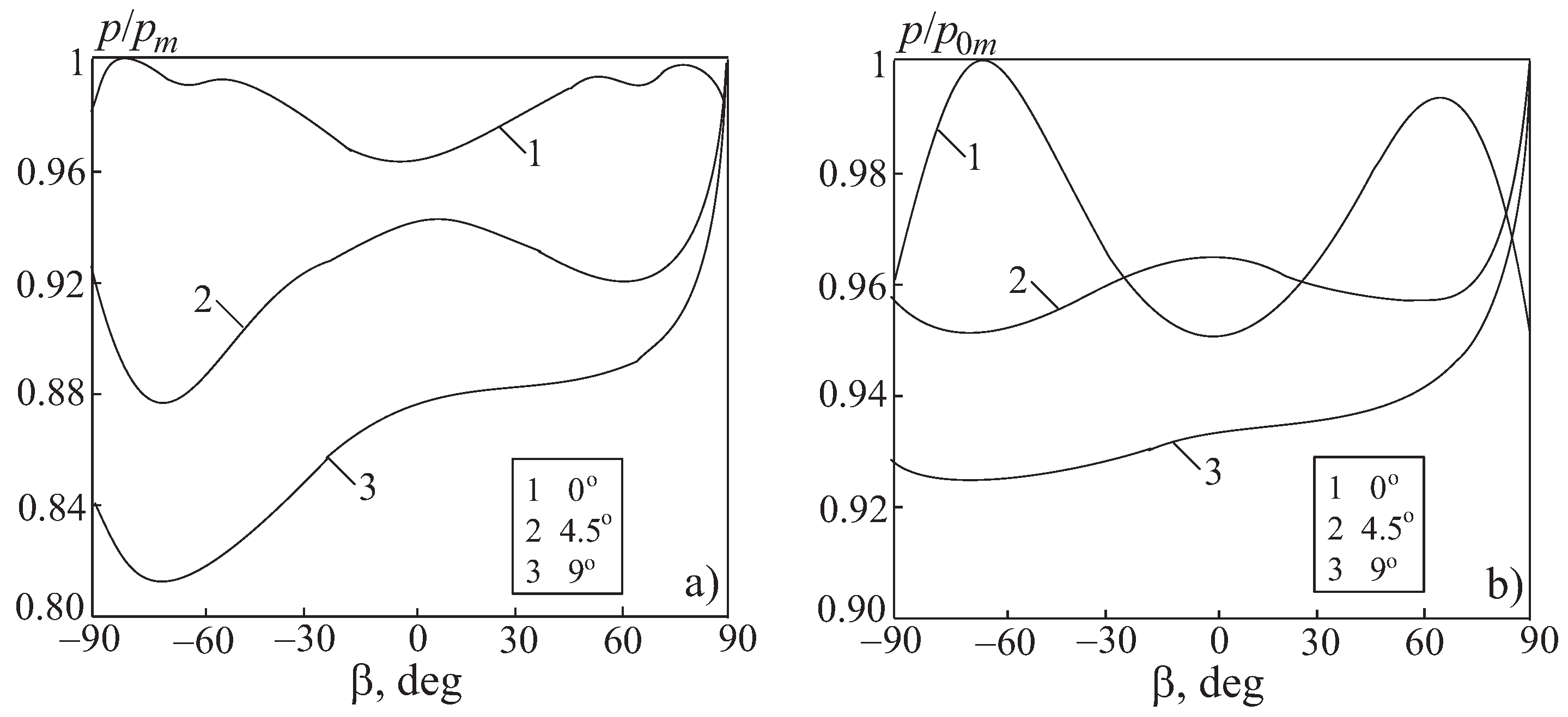
The distributions of pressure ( Pa) along the semicircle of the deceleration line of the rotary nozzle (along the radial generatrix of the coordinate mm in the direction of section ) are shown in Figure 8 and Figure 9 for cylindrical and star-shaped propellant channel. The calculation results are normalized to the maximum static or total pressure (the subscript m denotes the maximum pressure, and the subscript 0 denotes the total pressure), corresponding to the given angle of rotation of the nozzle and given in Table 1). There are significant differences and irregularities in the pressure distributions for cylindrical and star-shaped channels, due to both the shape of the channel and the asymmetry of the flow around the recessed rotary nozzle.
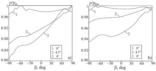
Figure 8.
Distributions of static pressure (a) and total pressure (b) along stagnation line for various angles of nozzle rotations for cylindrical channel.
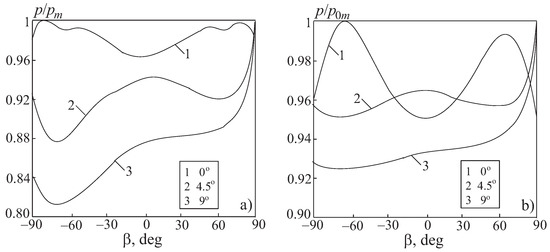
Figure 9.
Distributions of static pressure (a) and total pressure (b) along stagnation line for various angles of nozzle rotations for star-shaped channel.

Table 1.
Maximal pressure (MPa) for the various angles of nozzle rotation.
7.2. Velocity Distributions in Nozzle Throat
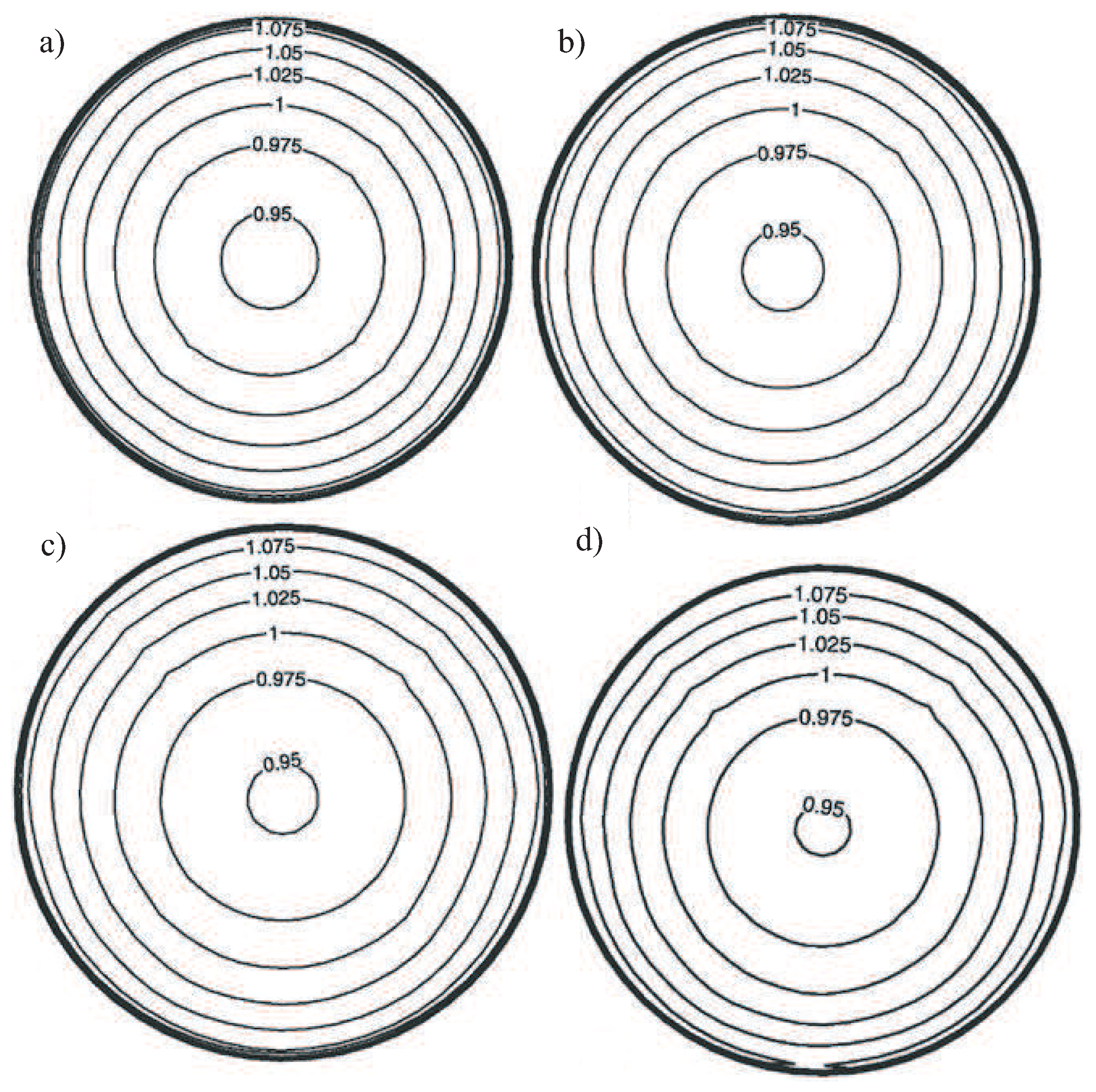
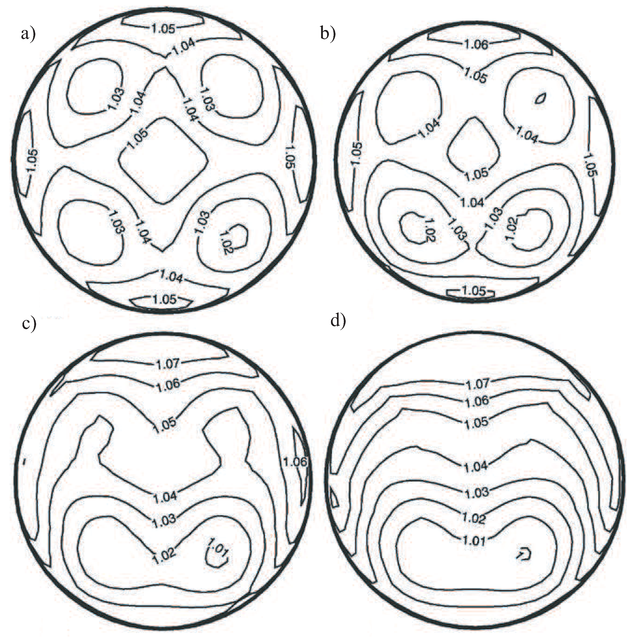
The contours of the Mach number in the throat section of the nozzle for different angles of its deviation from the axisymmetric position are shown in Figure 10 and Figure 11 for cylindrical and star-shaped propellant channels.

Figure 10.
Contours of Mach number in nozzle throat for cylindrical channel for (a), (b), (c), (d).
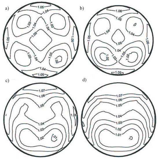
Figure 11.
Contours of Mach number in nozzle throat for star-shape channel for (a), (b), (c), (d).
In the case of a cylindrical channel, the flow pattern in the critical section undergoes comparatively small changes when the angle of rotation of the nozzle changes, and the Mach number contours retain the shape of concentric circles (Figure 10). As the angle of rotation of the nozzle increases from 0 to 9 degrees, the diameter of the circles corresponding to the same Mach number decreases, and their center shifts towards the rotation of the nozzle (vertically downward in the figure).
With the outflow of combustion products from the star-shaped channel, the flow pattern in the critical section becomes more complicated (Figure 11). For the initial position of the nozzle, traces of beams are visible, between which zones are formed with lines of equal values of the Mach number, which have the form of concentric circles (Figure 11a). Changing the angle of rotation of the nozzle from 0 to 6 degrees has a significant impact on the distribution of flow quantities. In this case, the beam traces become more blurred (the zones of influence of individual beams merge), and some condensation of lines of equal values of the Mach number takes place (Figure 11b,c). The flow remains symmetric, but the symmetry is determined not by the sector of the star, but by the sweeping plane of the nozzle. A further increase in the nozzle deflection angle to (Figure 11d) causes only small perturbations of the flow quantities in comparison with the rotation angle equal to . In this case, the picture of the level lines resembles the case corresponding to the outflow of combustion products from a cylindrical channel (Figure 10). The difference is that there are two circle centers for a star-shaped channel.
7.3. Velocity Distributions in Sweeping Plane
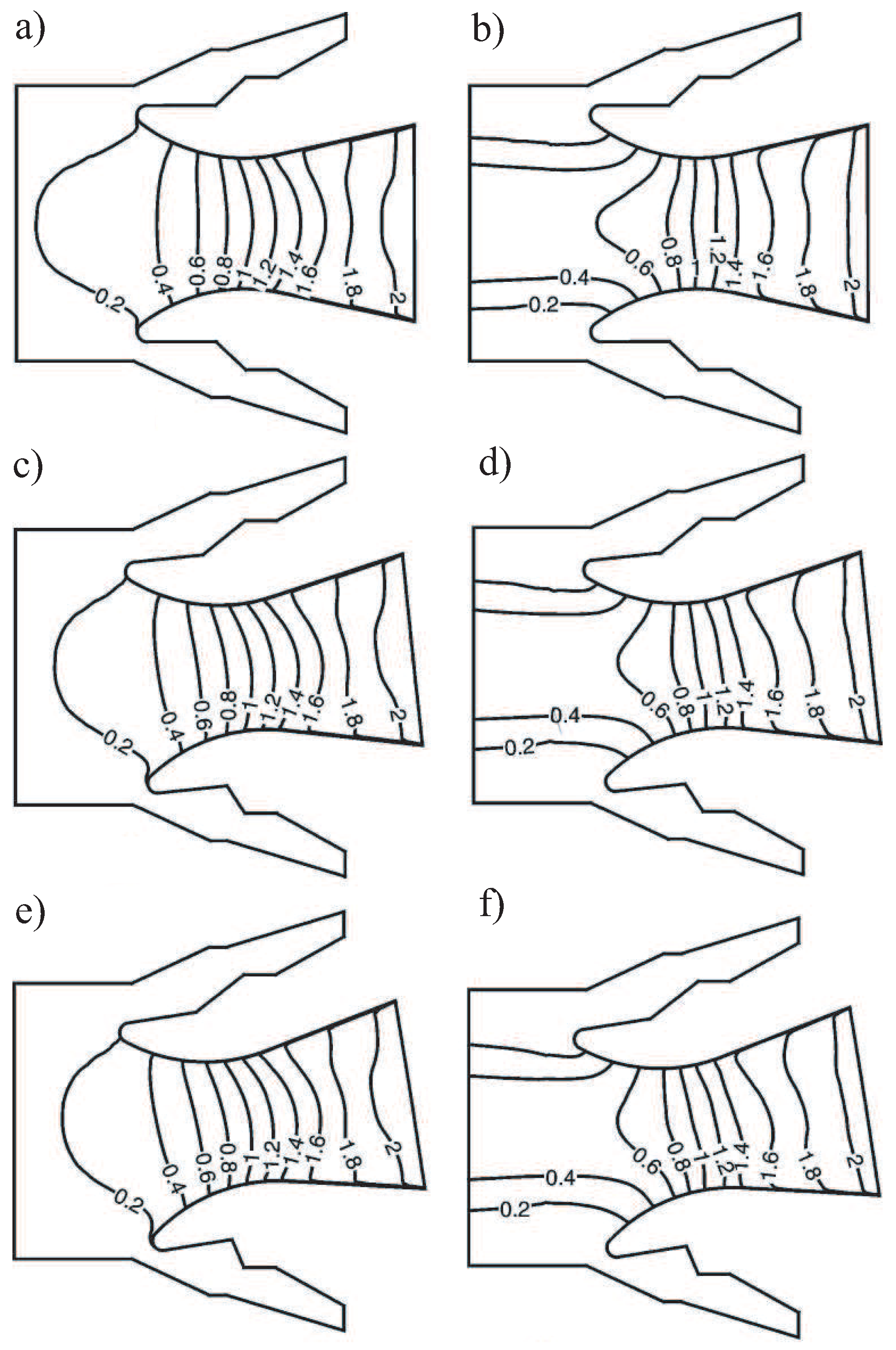
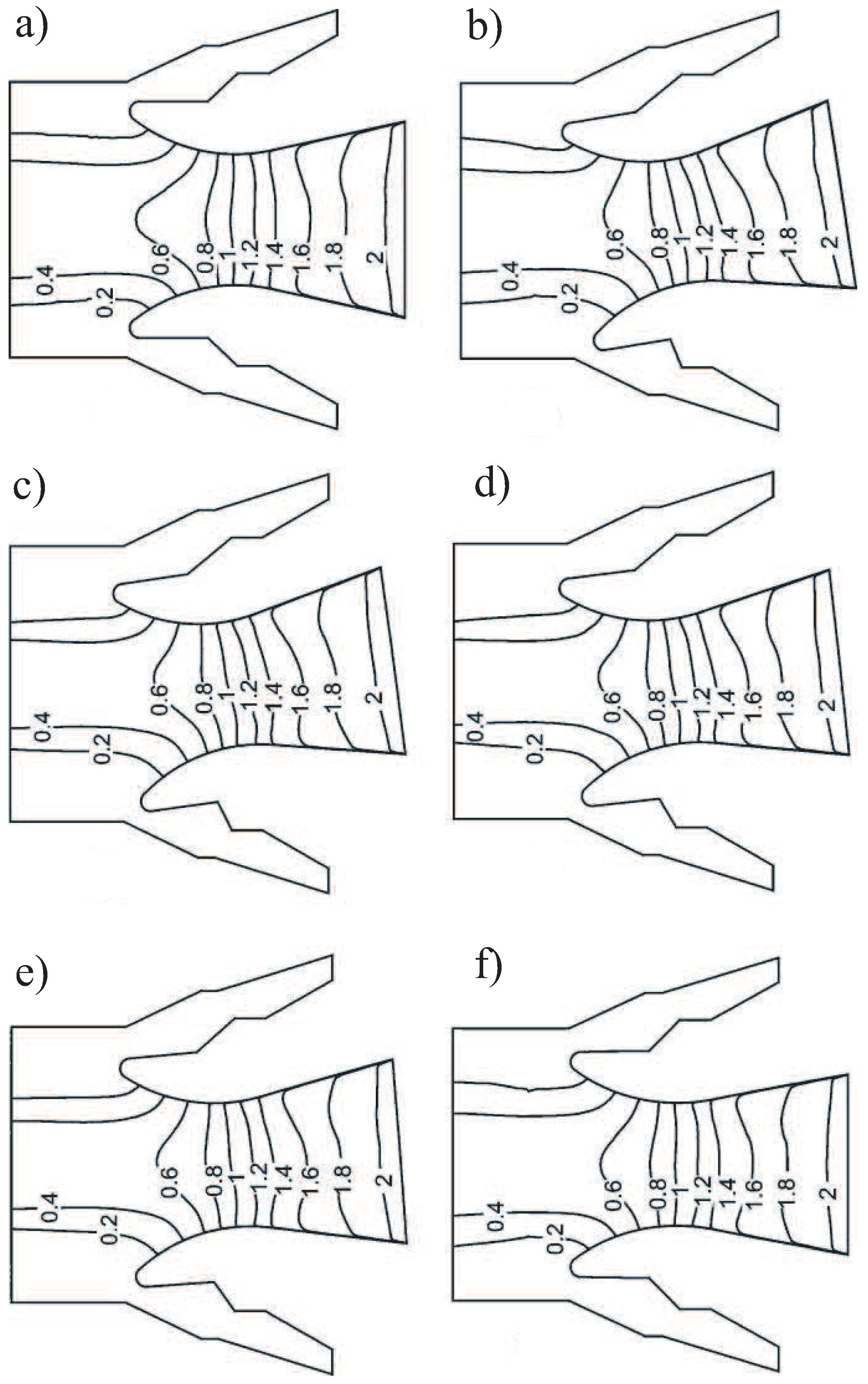
Comparison of the Mach number distributions in the nozzle sweeping plane is shown in Figure 12 for the cases of the outflow of combustion products from a cylindrical (Figure 12a,c,e) and a star-shaped (Figure 12b,d,f) propellant channels. The influence of the shape of the propellant channel is traced in Figure 12a,b, corresponding to the sweeping plane of the nozzle at a zero angle of its rotation. The use of a star-shaped channel leads to an increase in the velocity at the inlet to the pre-nozzle volume in comparison with a cylindrical channel at the same flow rate. In this case, the velocity characteristics of the flow in the vicinity of the stagnation points turn out to be lower than at the outflow from the cylindrical channel.
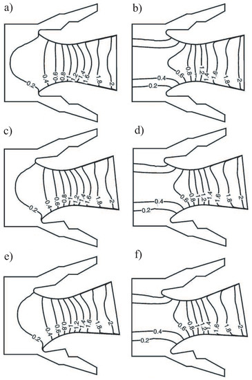
Figure 12.
Contours of Mach number in nozzle sweeping plane for (a,b), (c,d), (e,f).
The sound lines in the throat section of the nozzle has a different shape for cylindrical and star-shaped propellant channels. When the combustion products outflow from the cylindrical channel in the throat of the nozzle, the classical shape of the sonic line is formed, which is an arc of a circle (Figure 12a). In the case of a star-shaped channel, the Mach number contours in the critical section have a form close to a straight line (Figure 12b). In the supersonic part of the nozzle, the shape of the Mach contours is distorted, which is associated with both the influence of boundary conditions and the presence of nozzle shock waves.
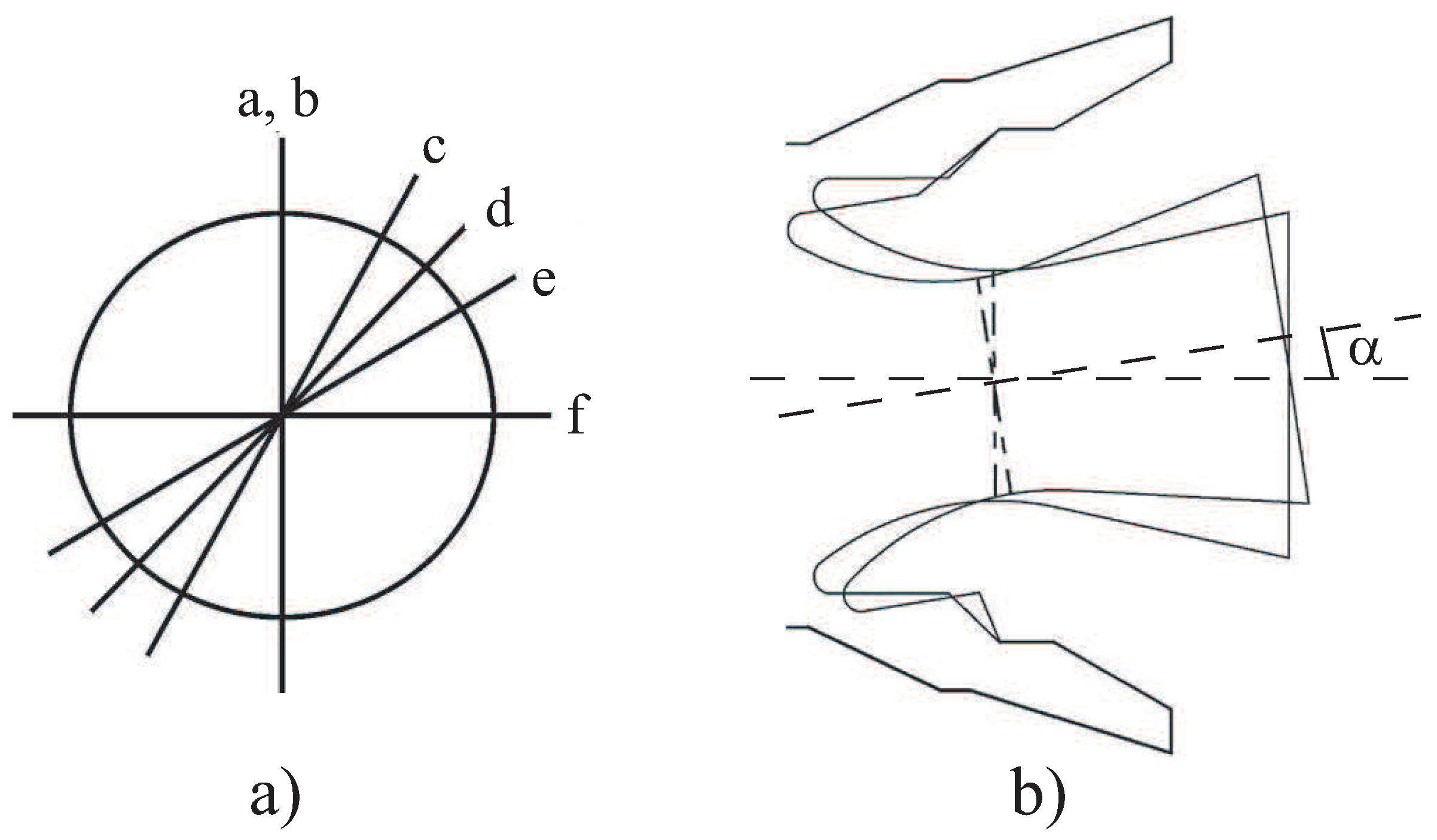
Control sections located at a certain angle to the nozzle sweeping plane are shown in Figure 13. Section a corresponds to the swinging plane of the nozzle without turning it, and section b corresponds to the sweeping plane of the nozzle with its rotation at a given angle. Sections c–f correspond to planes located at angles of , , , and to the nozzle sweeping plane.
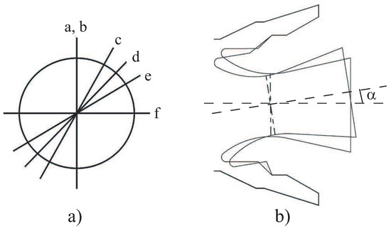
Figure 13.
Locations of control sections (a) and nozzle rotation on angle (b).
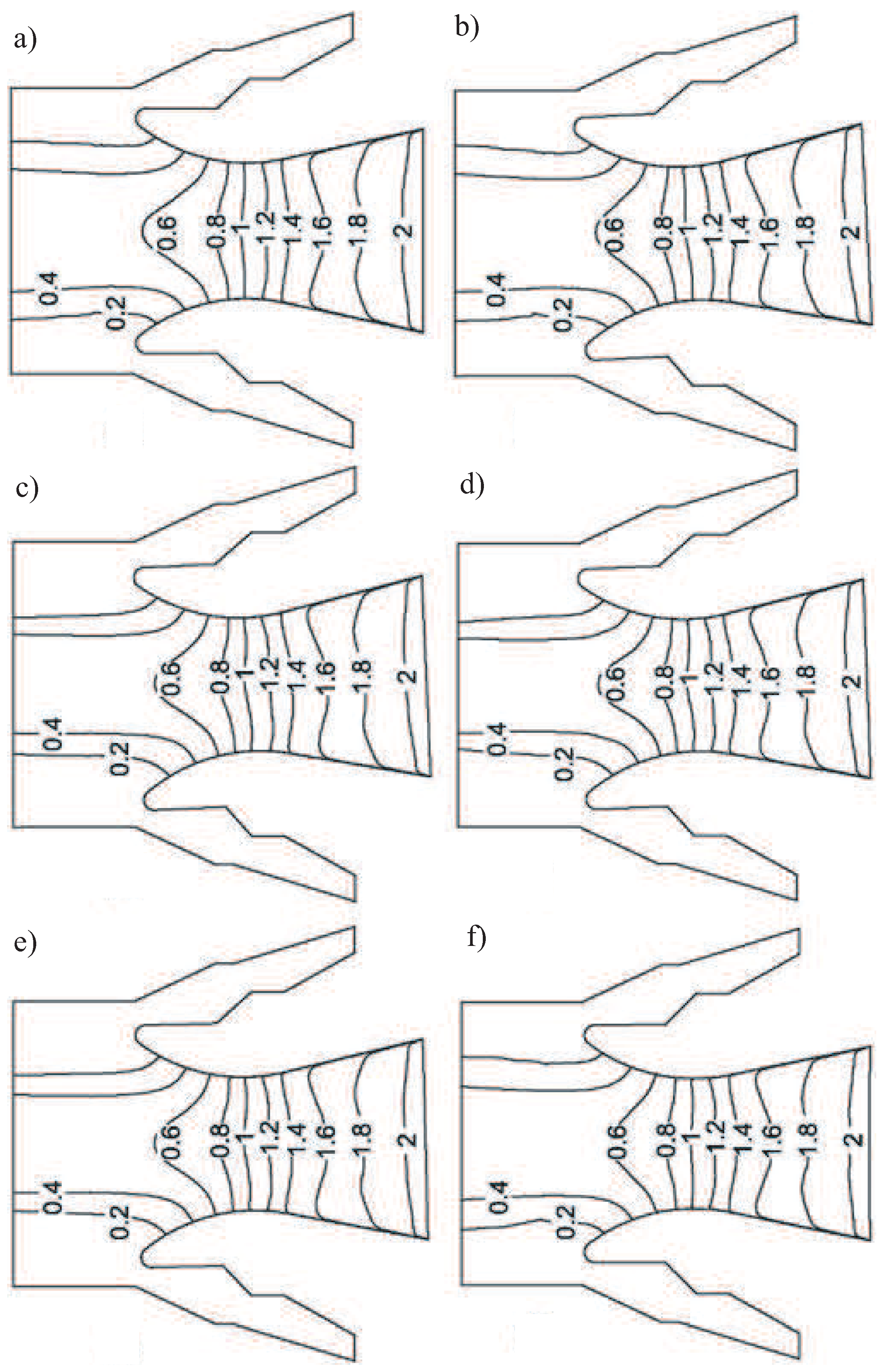
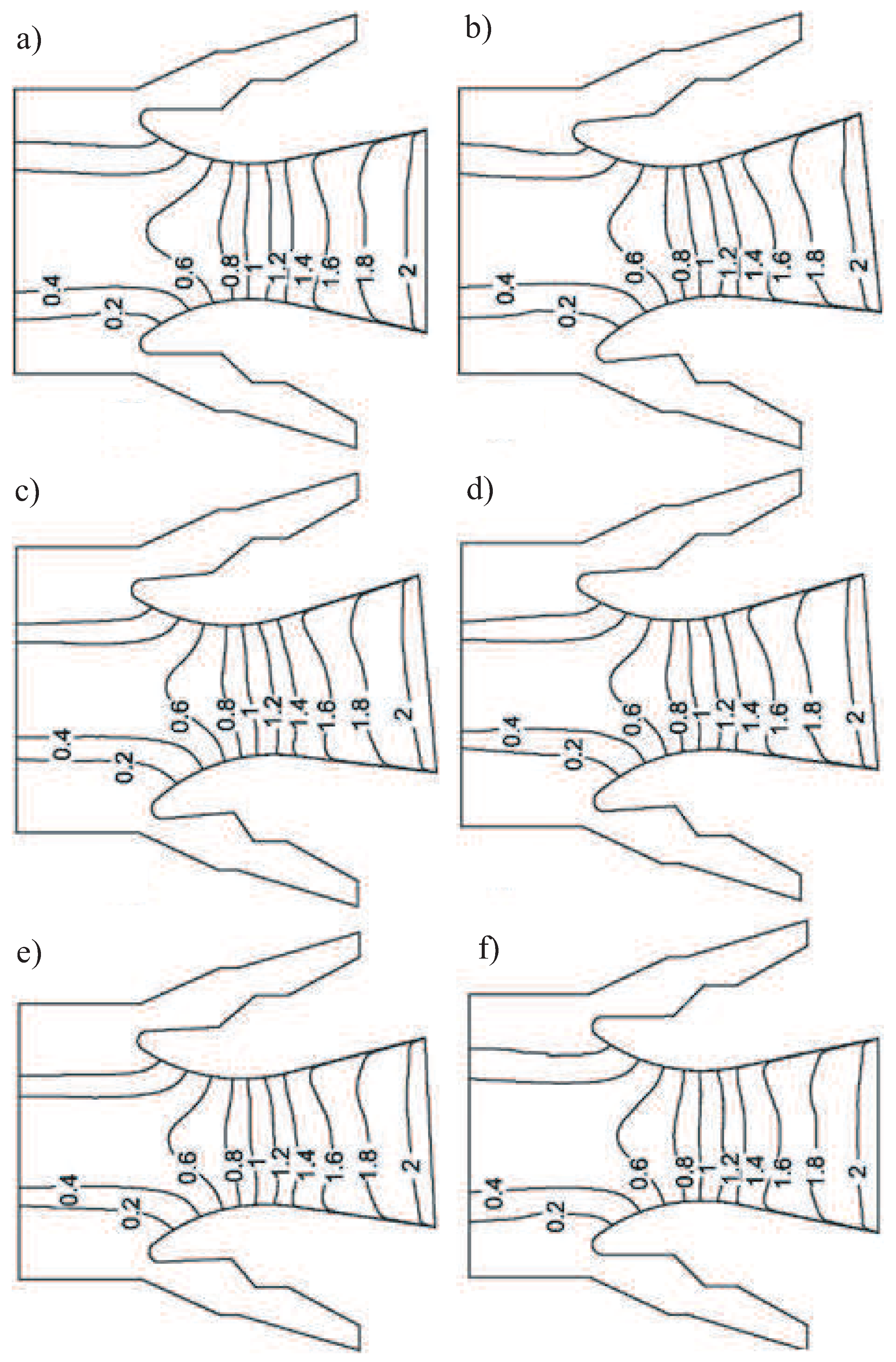
The Mach number distributions in various cross sections located at a certain angle to the sweeping plane of the rotating nozzle are shown in Figure 14, Figure 15 and Figure 16 for the case of the outflow of combustion products from the star-shaped propellant channel. Fragments a correspond to the sweeping plane of the nozzle without its rotation, and fragments b correspond to the sweeping plane of the nozzle with its rotation at a given angle. Fragments c–f correspond to sections located at angles of (fragment c), (fragment d), (fragment e), and (fragment f) to the nozzle swing plane and shown in Figure 13. An increase in the angle of rotation of the nozzle from 3 to does not lead to a qualitative restructuring of the flow pattern, causing only quantitative changes in the characteristics of the flow.
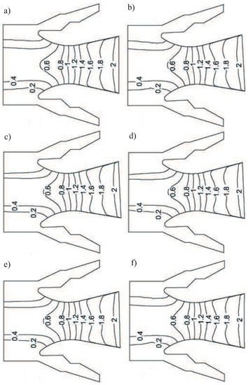
Figure 14.
Contours of Mach number in nozzle for various planes for angle of nozzle rotation (a–f).
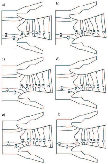
Figure 15.
Contours of Mach number in nozzle for various planes for angle of nozzle rotation (a–f).
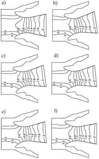
Figure 16.
Contours of Mach number in nozzle for various planes for angle of nozzle rotation (a–f).
7.4. Vortical Structure
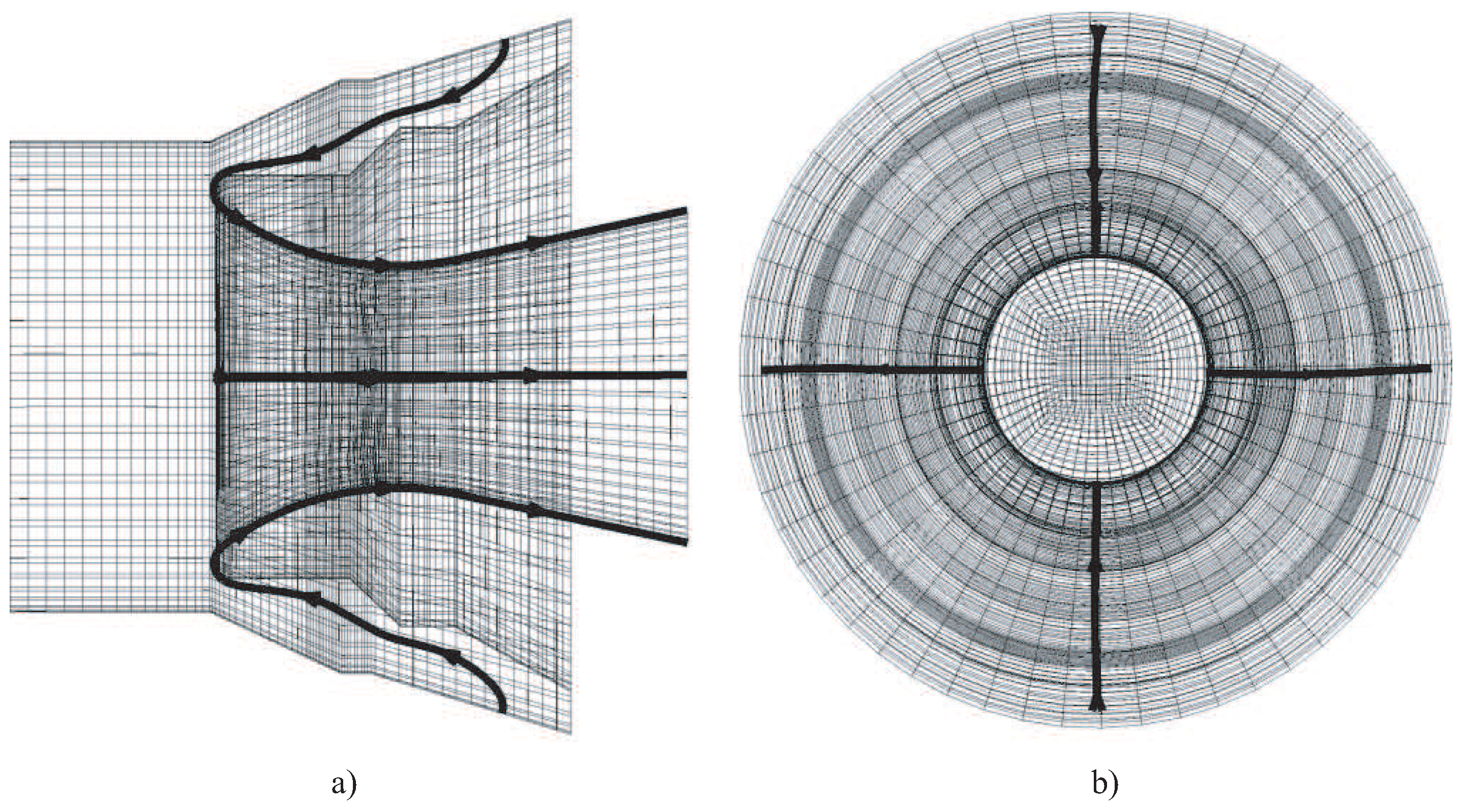
The formation of a vortex flow structure in the vicinity of the rear nozzle cover is considered when the angle of rotation of the nozzle is changed. To visualize the spatial flow pattern, streamlines are used in the part of interest in the computational domain. A typical picture of the movement of combustion products near the rear nozzle cover during their outflow from the cylindrical channel is shown in Figure 17 (no rotation of the nozzle). Figure 17a corresponds to the plane, and Figure 17b corresponds to the plane. In this case, a turn and some compression of the flow outflowing from the pre-nozzle space is observed by a more intense main flow in the propellant channel.
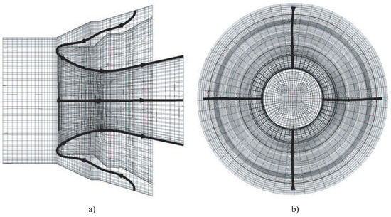
Figure 17.
Streamlines near the rear nozzle head for cylindrical channel (): side view (a) and face view (b).
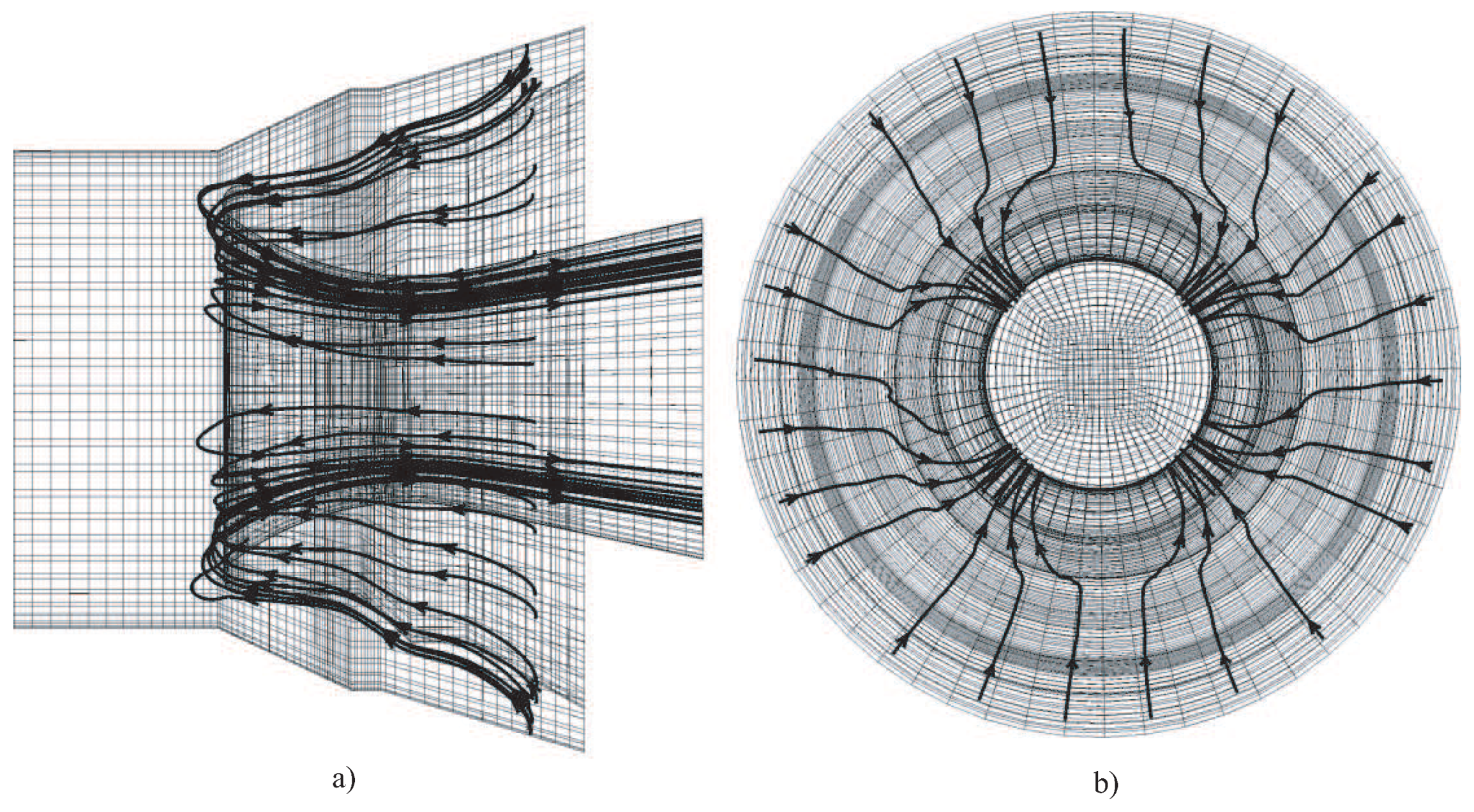
With the outflow of combustion products from a star-shaped channel, the flow pattern becomes more complicated (Figure 18). Figure 18a corresponds to the plane, and Figure 18b corresponds to the plane. Under the influence of the countercurrent, the flow pattern ceases to be axisymmetric and becomes cyclically symmetric. In this case, four bundles are formed, displaced relative to the rays of the star by an angle equal to , which leads to an increase in dynamic loads on the corresponding sections of the nozzle.

Figure 18.
Streamlines near the rear nozzle head for star-shaped channel (): side view (a) and face view (b).
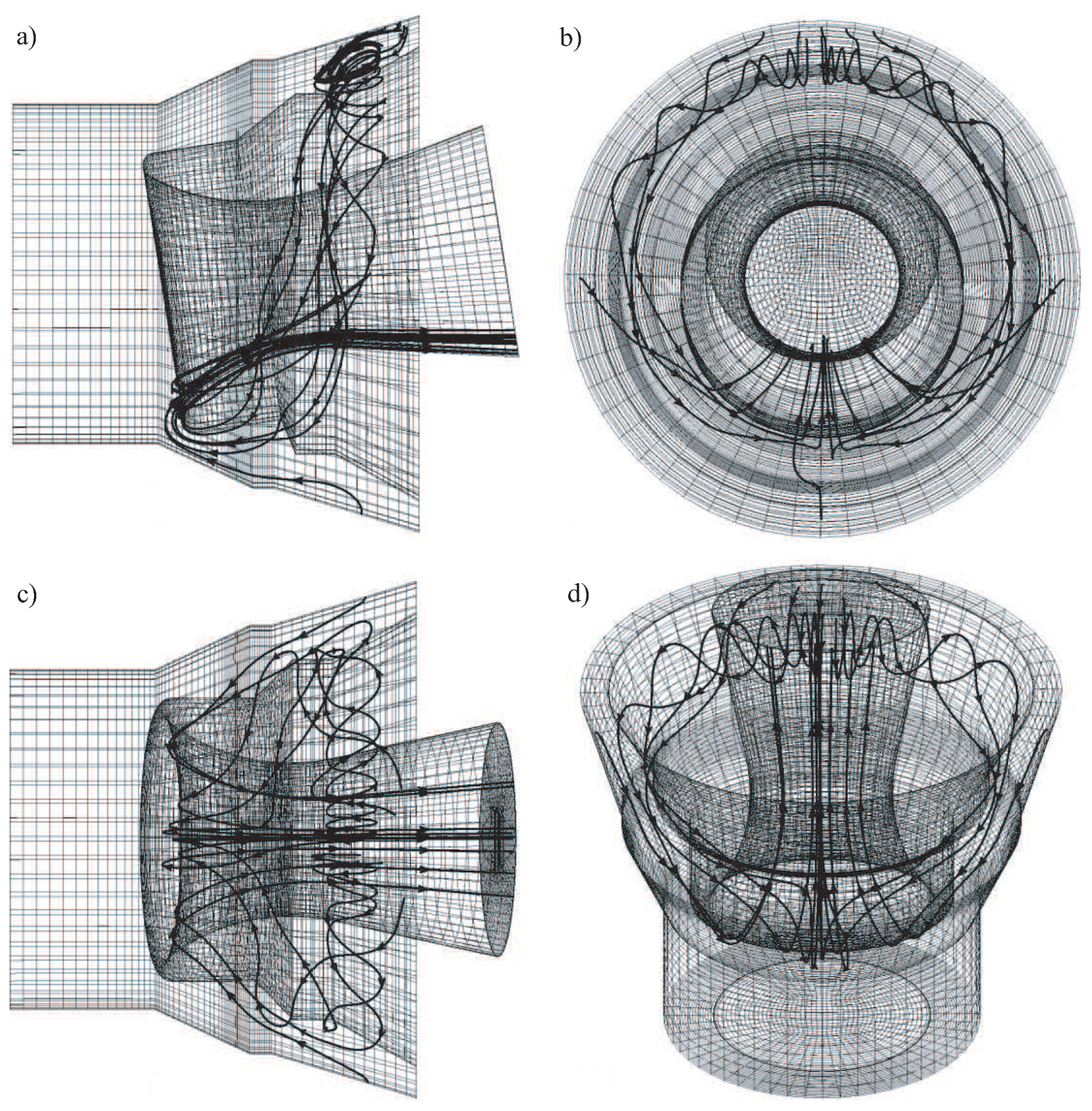
At a non-zero angle of deflection of the nozzle from the axisymmetric position, further complication of the spatial flow pattern occurs, which is formed in the vicinity of the rear nozzle cover (Figure 19). Figure 19a corresponds to the xy plane, Figure 19b corresponds to the yz plane, Figure 19c corresponds to the xz plane, and Figure 19d corresponds to a three-dimensional image of the nozzle (the x axis is directed vertically upward). The peculiarity of the flow is that due to the low velocities characteristic of a given zone, the main flow around the nozzle interacts with the counter flow, pressing it. Streamlines form a bundle concentrated on the leeward side of the nozzle, and local recirculation flow zones are also formed.
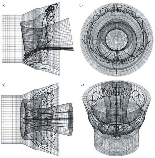
Figure 19.
Streamlines near the rear nozzle head for cylindrical channel (): view in plane (a), view in plane (b), view in plane (c), three-dimensional view (d).
The solution obtained for the case of the outflow of combustion products from a star-shaped channel shows that, in contrast to the cylindrical channel, there are no local recirculation zones (Figure 20). Figure 20a corresponds to the plane, Figure 20b corresponds to the plane, Figure 20c corresponds to the plane, and Figure 20d corresponds to a three-dimensional image of the nozzle (the x axis is directed vertically upward). In the pre-nozzle volume, a part of the gas coming from the slots unfolds in the inter-nozzle space (the gap between the end of the charge and the nozzle bottom), forming vortex structures, and enters the nozzle.
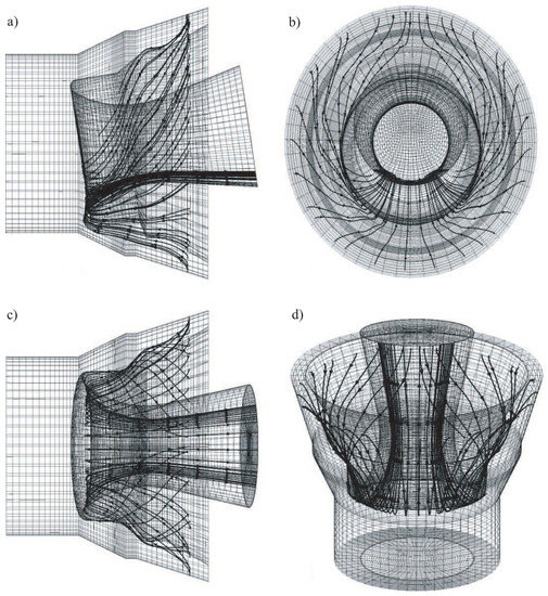
Figure 20.
Streamlines near the rear nozzle head for cylindrical channel (): view in plane (a), view in plane (b), view in plane (c), three-dimensional view (d).
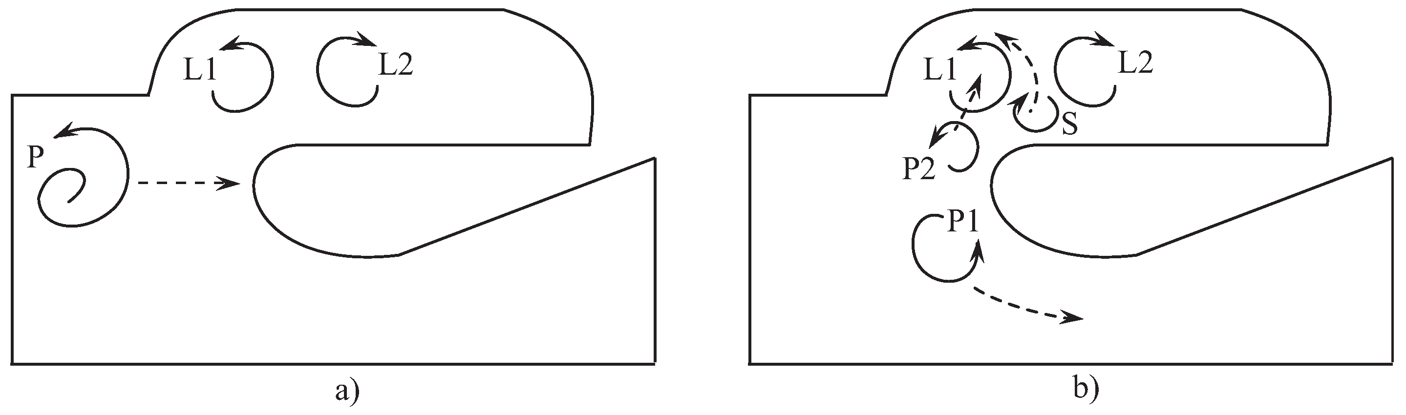
The development of vortical flow structure shows in Figure 21. The vortex formation begins with a vortex P (Figure 21a). This vortex impinges on the nozzle head and splits into two smaller separate vortices, P1 and P2. The interaction of vortex P with the boundary layer on the nozzle wall leads to formation of secondary counter-rotating vortex S (Figure 21b). Then, the vortex P2 merges with vortex L1. In this way vortex P2 feeds vortex L1 compensating energy dissipation due to viscous effects, so vortex L1 has an averaged constant intensity. The counter-rotating vortex S is driven by the induced velocity of vortex L1. This produces a clearly visible up-and-down movement of the center of vortex L1. The flow pattern is in qualitative agreement with experimental data observed in [2].
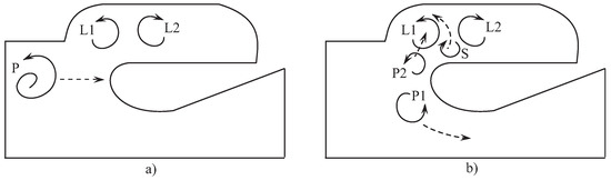
Figure 21.
Formation (a) and development (b) of vortical structure of the flow.
7.5. Comparison of Steady and Unsteady Solutions
Within the framework of the quasi-stationary formulation of the problem, for simplicity, it is assumed that the time for processing the command to change the angle of rotation of the nozzle is much less than the time for changing the flow quantities in the pre-nozzle volume.
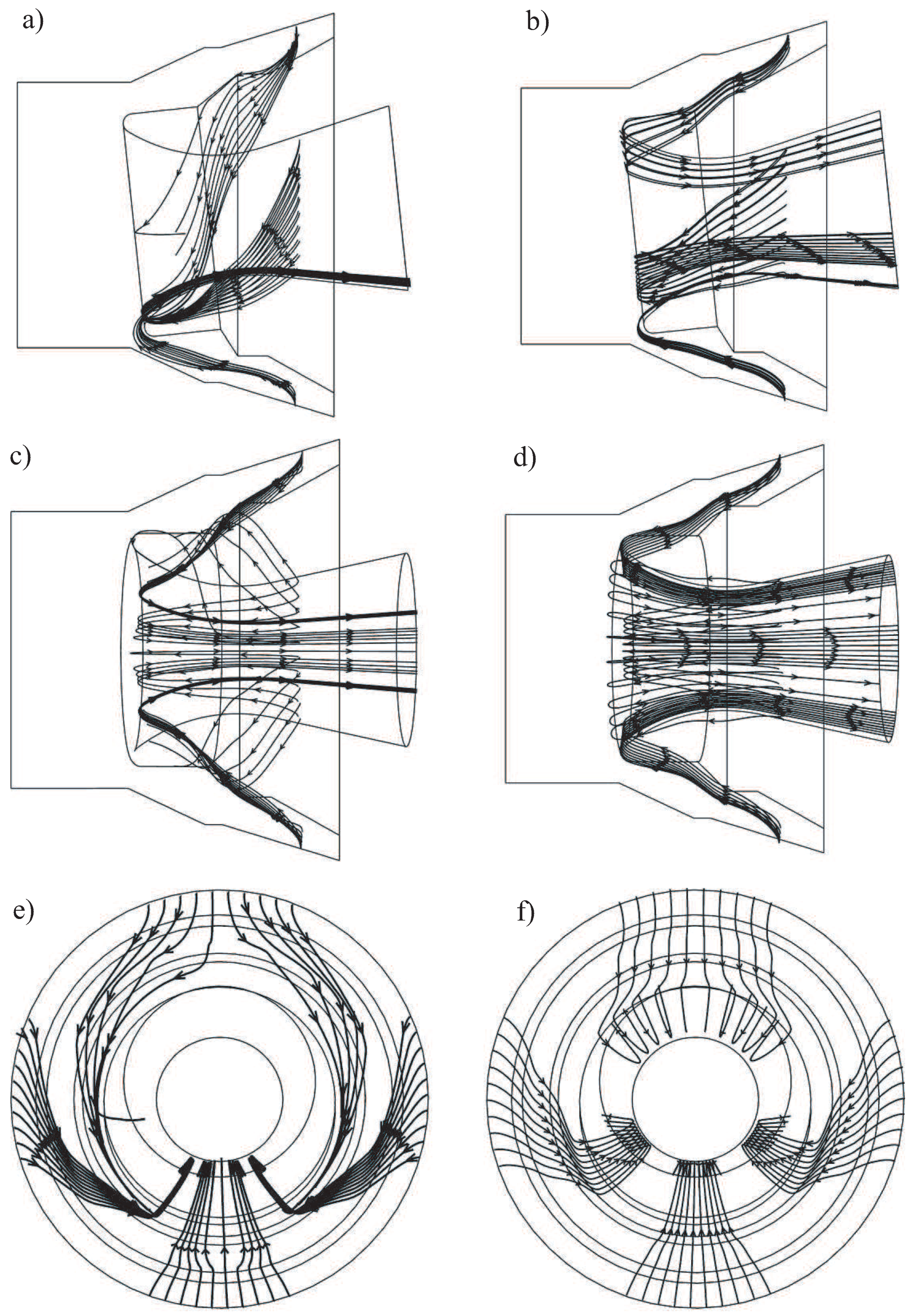
A comparison of the solutions obtained in the framework of the unsteady formulation of the problem (the motion of the nozzle is taken into account) and the quasi-stationary approach (the solution is sought for a fixed position of the nozzle) is shown in Figure 22 for a cylindrical propellant channel. Figure 22a,b correspond to the plane, Figure 22c,d correspond to the plane, and Figure 22e,f correspond to the plane. The spatial structure of the flow formed in the pre-nozzle volume undergoes significant changes depending on the choice of approach to solving the problem. In particular, the difference between the solutions obtained within the framework of the quasi-stationary and unsteady approaches lies in the intensity of vortex bundles formed on the surface of the leeward part of the recessed nozzle.
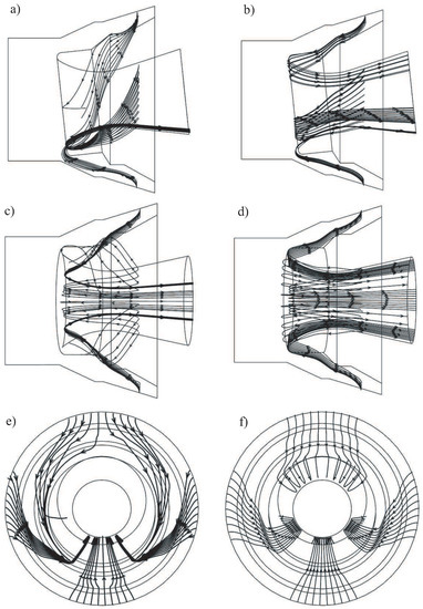
Figure 22.
Solutions computed with unsteady formulation (a,c,e) and steady formulation (b,d,f) for .
7.6. Mass Flow Rate
When the rotary vectorable nozzle operates as a control element, its flow characteristics change due to a change in the angle made by its axis with the direction of the channel flow.
As an example, a propellant with a cylindrical channel and a supra-nozzle cylindrical section of the channel are considered. The following parameters are varied in the calculations: the ratio of the flow rates from the channel and supra-nozzle parts , the angle of rotation of the nozzle , the linear displacement of the nozzle from the nominal position , where D is the diameter of the over-nozzle part of the charge, and is the channel diameter. For the convenience of transferring the obtained data to other cases, the obtained value of the discharge coefficient is normalized to its value in the absence of disturbances.
The influence of the linear displacement of the nozzle on the flow quantities of the submerged nozzle is shown in Figure 23. In Figure 23a, the results correspond to a fixed angle of rotation of the nozzle and different ratios of the flow rates from the channel and the supra-nozzle part of the propellant, in particular, (line 1), (line 2) and (line 3). In Figure 23b, the results correspond to a fixed flow rate ratio and different nozzle rotation angles, in particular, (line 1), (line 2), and (line 3).
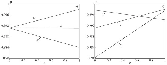
Figure 23.
Dependance of rate coefficient on nozzle linear movement for (a) and (b).
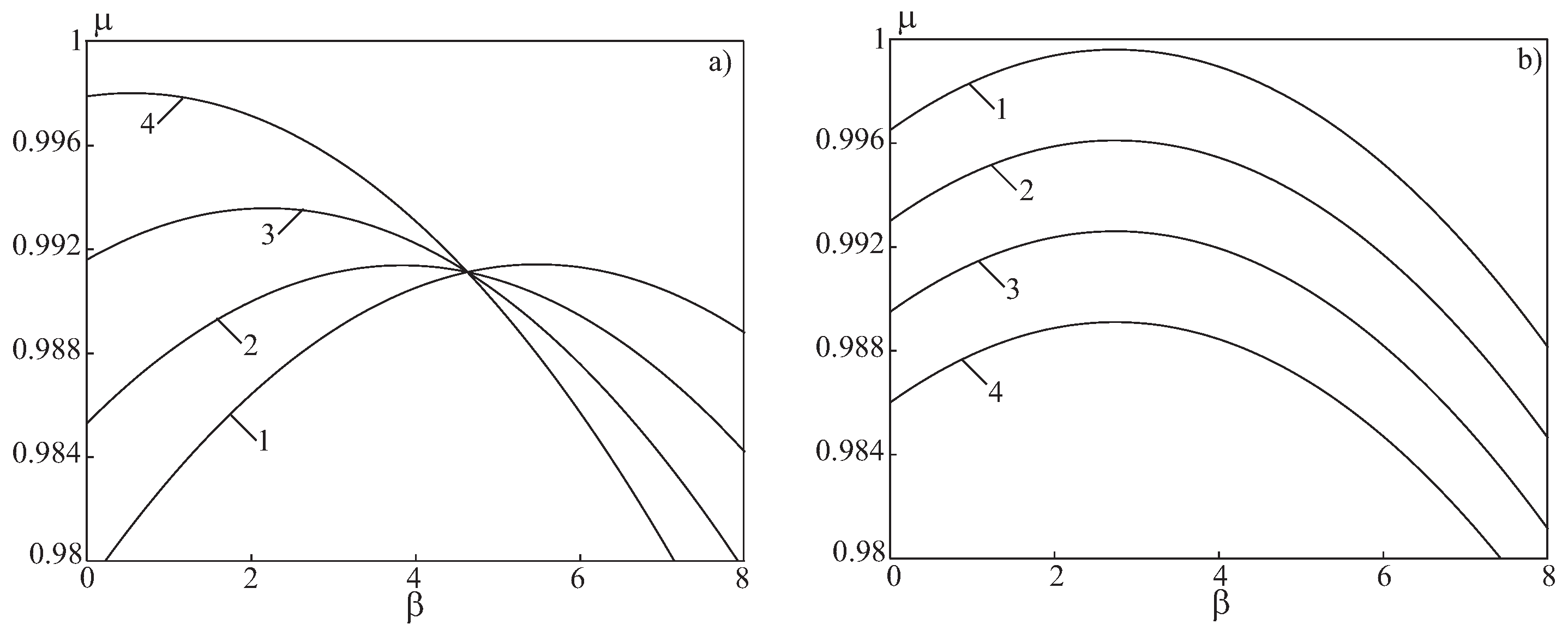
The influence of the angle of rotation of the nozzle on the flow characteristics of the submerged nozzle is shown in Figure 24. In Figure 24a, the results correspond to a fixed ratio of flow rates and various linear displacements of the nozzle, in particular, (line 1), (line 2), (line 3) and (line 4). In Figure 24b, the results correspond to a fixed linear displacement of the nozzle and different flow rate ratios, in particular, (line 1), (line 2), (line 3), and (line 4).
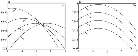
Figure 24.
Dependance of rate coefficient on angle of nozzle rotation for (a) and (b).
The experimental data from [2] show that the significance of linear influences is negligible, and the nozzle deflection angle is the only parameter that affects the flow rate independently in the form of a quadratic effect. With an additional linear displacement of the nozzle axis, a mixed effect occurs from the combined influence of the parameters and , which can contribute to an increase in the flow coefficient. Since the displacement of the frontal part of the nozzle at angular and linear displacements can be arbitrary, these effects can compensate for each other, which determines the presence of a maximum. The magnitude of the linear displacement enters into the regression equation as a component of two mixed effects, and these effects have different signs, therefore, the influence of on the discharge coefficient is not unambiguous. The cost ratio is also part of the mixed effects, and since this effect is negative, its effect is one-sided.
8. Conclusions
For the design and improvement of solid propellant rocket motors, information is required on the in-chamber processes that determine the flow and thrust characteristics of the product. The design of SRM thrust vector controls is associated with the determination of the loads acting on the nozzle. The problem of determining the gas-dynamic forces acting on the structural elements of a stationary nozzle with a symmetrical flow of combustion products along the nozzle does not present any difficulties and is solved by calculating the pressure distribution along the length of the nozzle with subsequent integration of the pressure forces in the main direction. The asymmetry of the flow caused by the curvature of the gas-dynamic path leads to a redistribution of pressure in the cross-sections of the channel and the need to use numerical methods to calculate the thrust characteristics.
Numerical simulation of unsteady turbulent flow of a viscous compressible gas in a SRM propellant channel with a rotary vectorable nozzle is carried out. For CFD calculations, the finite volume method and movable mesh structures are used. The results obtained indicate the implementation of a complex spatial flow in the near-nozzle space, in which the nozzle flow has the ability to deeply penetrate into the space above the nozzle and into the region of the rear nozzle cover. When the angle of deflection of the nozzle from the axisymmetric position is non-zero, the spatial pattern of the flow that forms in the vicinity of the rear nozzle cover becomes more complicated. The peculiarity of the flow is that due to the low velocities characteristic of a given zone, the main flow around the nozzle interacts with the counter flow, pressing it. Streamlines form a bundle concentrated on the leeward side of the nozzle, and local recirculation flow zones are also formed.
Author Contributions
Conceptualization, V.E. and S.D.; methodology and software, S.D.; validation, V.E. and K.V.; formal analysis, K.V.; investigation, S.D.; writing—original draft preparation, K.V.; writing—review and editing, K.V.; visualization, S.D.; supervision, V.E.; project administration, V.E.; funding acquisition, K.V. All authors have read and agreed to the published version of the manuscript.
Funding
The research is partially funded by the Ministry of Science and Higher Education of the Russian Federation as part of World-class Research Center program: Advanced Digital Technologies (contract No. 075-15-2020-903 dated 16 November 2020).
Institutional Review Board Statement
Not applicable.
Informed Consent Statement
Not applicable.
Data Availability Statement
Not applicable.
Conflicts of Interest
The authors declare no conflict of interest.
References
- Shishkov, A.A.; Panin, S.D.; Rumyancev, B.V. Working Processes in Rocket Engines of Solid Fuel; Mechanical Enginering: Moscow, Russia, 1971. [Google Scholar]
- Saveliev, S.K.; Emelyanov, V.N.; Bendersky, B.Y. Experimental Methods of Investigation of Gas Dynamics of SRM; Nedra: St. Petersburg, Russia, 2007. [Google Scholar]
- Pirumov, U.G.; Roslyakov, G.S. Gas Dynamics of Nozzles; Nauka: Moscow, Russia, 1990. [Google Scholar]
- Volkov, K.N.; Emelyanov, V.N.; Teterina, I.V.; Yakovchuk, M.S. Gas Flows in Nozzle of Energy Systems; Publishing House of Physical and Mathematical Literature: Moscow, Russia, 2016. [Google Scholar]
- Hagemann, G.; Immich, H.; Nguyen, T.V.; Dumnov, G.E. Advanced rocket nozzles. J. Propuls. Power 1998, 14, 620–633. [Google Scholar] [CrossRef]
- Shimizu, T.; Kodera, M.; Tsuboi, N. Internal and external flow of rocket nozzle. J. Earth Simulator 2008, 9, 19–26. [Google Scholar]
- Volkov, K.N.; Denisihin, S.V.; Emelyanov, V.N. Formation of vortex structures in the prenozzle space of an engine with a vectorable thrust nozzle. J. Eng. Phys. Thermophys. 2016, 89, 660–670. [Google Scholar] [CrossRef]
- Volkov, K.N.; Denisikhin, S.V.; Emelyanov, V.N.; Teterina, I.V. Flow of combustion products containing condensed-phase particles over a recessed vectorable jet nozzle. J. Eng. Phys. Thermophys. 2017, 90, 1140–1146. [Google Scholar] [CrossRef]
- Volkov, K.N.; Denisikhin, S.V.; Emelyanov, V.N. Gas dynamics of a recessed nozzle in its displacement in the radial direction. J. Eng. Phys. Thermophys. 2017, 90, 932–940. [Google Scholar] [CrossRef]
- Zaikovskii, V.N.; Kiselev, S.P.; Kiselev, V.P. Large-scale streamwise vortices in the supersonic part of a permeable nozzle. J. Appl. Mech. Tech. Phys. 2005, 46, 670–676. [Google Scholar] [CrossRef]
- Zaikovskii, V.N.; Melamed, B.M. Vortical flows in nozzles of SRM. In Stability of Flow of Homogeneous and Heterogeneous Fluids; Russian Academy of Sciences Siberian Branch, Institute of Theoretical and Applied Mechanics: Novosibirsk, Russia, 2000; pp. 183–186. [Google Scholar]
- Volkov, K.N.; Emelaynov, V.N. Gas Flows Induced by Fluid Injection in Energy Systems; Publishing House of Physical and Mathematical Literature: Moscow, Russia, 2011. [Google Scholar]
- Emelyanov, V.N.; Volkov, K.N. Mathematical models of three-dimensional turbulent flows in the ducts with fluid injection. Math. Model. 2004, 16, 41–63. [Google Scholar]
- Bendersky, B.Y.; Tenenev, V.A. Spatial subsonic flows in areas with composite geometry. Math. Model. 2001, 13, 121–127. [Google Scholar]
- Bendersky, B.Y.; Saushin, P.N.; Tenenev, V.A.; Chernova, A.A. Features of simulaton of intra-chamber processes in energy systems with submerged nozzle. Austronautics Rocket. Eng. 2012, 1, 156–161. [Google Scholar]
- Volkov, K.N.; Emelyanov, V.N.; Kurova, I.V. Flow and motion of condensed-phase particles in the prenozzle space of solid-propellant rocket motors. J. Eng. Phys. Thermophys. 2012, 85, 723–731. [Google Scholar] [CrossRef]
- Myshenkov, E.V.; Myshenkova, E.V. Hysteresis phenomena in a plane rotatable nozzle. Fluid Dyn. 2010, 4, 667–678. [Google Scholar] [CrossRef]
- Cortopassi, A.; Boyer, E.; Acharya, R.; Kuo, K. Design of a solid rocket motor for characterization of submerged nozzle erosion. AIAA Paper 2008. [Google Scholar] [CrossRef]
- Cortopassi, A.; Boyer, E.; Kuo, K. Update: A subscale solid rocket motor for characterization of submerged nozzle erosion. AIAA Paper 2009. [Google Scholar] [CrossRef]
- Anthoine, J.; Buchlin, J.-M.; Hirschberg, A. Effect of nozzle cavity on resonance in large SRM: Theoretical modeling. J. Propuls. Power 2002, 18, 304–311. [Google Scholar] [CrossRef]
- Toth, B.; Lema, M.R.; Rambaud, P.; Anthoine, J.; Steelant, J. Single-phase internal flowfield validation with an experimental solid rocket motor model. J. Propuls. Power 2009, 25, 1311–1321. [Google Scholar] [CrossRef]
- Glushko, G.; Ivanov, I.; Kryukov, I. Numerical simulation of separated flow in nozzles. Phys. Chem. Kinet. Gas Dyn. 2010, 9, 142. [Google Scholar]
- Emelyanov, V.; Yakovchuk, M.; Volkov, K. Multiparameter optimization of thrust vector control with transverse injection of a supersonic underexpanded gas jet into a convergent-divergent nozzle. Energies 2021, 14, 4359. [Google Scholar] [CrossRef]


Publisher’s Note: MDPI stays neutral with regard to jurisdictional claims in published maps and institutional affiliations. |
© 2021 by the authors. Licensee MDPI, Basel, Switzerland. This article is an open access article distributed under the terms and conditions of the Creative Commons Attribution (CC BY) license (https://creativecommons.org/licenses/by/4.0/).