Abstract
The air–water interface in flowing systems remains a challenge to model, even in cases where the interface is essentially flat. This is because even though each side is governed by the Navier–Stokes equations, the stress balance which provides the boundary conditions for the equations involves properties associated with surfactants that are inevitably present at the air–water interface. Aside from challenges in measuring interfacial properties, either intrinsic or flow-dependent, the two-way coupling of bulk and interfacial flows is non-trivial, even for very simple flow geometries. Here, we present an overview of the physics associated with surfactant monolayers of flowing liquid and describe how the monolayer affects the bulk flow and how the monolayer is transported and deformed by the bulk flow. The emphasis is primarily on cylindrical flow geometries, and both Newtonian and non-Newtonian interfacial responses are considered. We consider interfacial flows that are solenoidal as well as those where the surface velocity is not divergence free.
1. Introduction
In this paper, which is dedicated to the late Prof. William W. Willmarth, we provide an overview of the hydrodynamics associated with surfactants (surface-active materials), due to their omnipresence in both natural and manmade systems. Our emphasis is on theoretical modeling of vortical flows with significant inertia, inspired by the work of Willmarth in free-surface turbulence. Our perspective was also shaped by Willmarth, who advised the PhD work of the first author, and strongly believed in carefully conducted experiments to discover new phenomena and closely coupled with theory/numerics. In that spirit, here we present the theoretical foundation for two-way coupling of inertial bulk flow with surfactant-covered interfaces. The stress–strain constitutive relation for Newtonian interfaces is first discussed and how it may be generalized. This work is a culmination of more than 25 years of collaboration between an experimenter in free-surface flows and a theoretical hydrodynamist.
Interfacial hydrodynamics can drastically alter the transfer of mass, momentum, and energy across the surface of a liquid due to the coupling to the bulk hydrodynamics. The importance of interfacial hydrodynamics is evident everywhere we look in nature, ranging from small scale systems such as the alveoli in the lungs [1] to CO transfer between the atmosphere and the oceans [2,3,4,5]. In manufacturing, interfacial hydrodynamics impacts everything from wet processing of micro-electronics to the production of polyurethane foam [6,7]. A recent development in the pharmaceutical manufacturing industry is the increased utilization of interfacial processing [8]. Yet, it is extraordinary how little is understood about interfacial hydrodynamics, how to predict it, and ultimately, how to control it.
Our understanding of interfacial hydrodynamics has come a long way from just knowing that oil can calm troubled waters, but we still have a long way to go. A major challenge of our time is manufacturing of pharmaceuticals, including monoclonal antibodies, at a global scale. For more than 50 years, pharmaceuticals have been produced using batch manufacturing which is a multi-step process involving synthesis, crystallization, blending, granulation and tableting. In between each stage, the products are tested, shipped and stored from one batch processing location to another. More recently, there has been a slow shift to continuous manufacturing, where the pharmaceuticals are produced simultaneously on a single process line, increasing both cost efficiency and product quality [9]. Among the challenges in designing these new processors for each manufacturing stage is how to mitigate adverse effects from hydrodynamic and interfacial stresses [10,11,12,13]. For example, in bioreactors where microbial factories such as E. coli are used to over-express therapeutic proteins, such as insulin via recombinant technologies, one must limit the range of shear stress imposed on the micro-organisms. After the protein is extracted, it must be purified and utilized at large concentrations—such as in injectable monoclonal antibodies. Proteins can denature and aggregate as a result of large shear and/or exposure to hydrophobic interfaces. Surfactant additives are utilized in various stages of pharmaceutical manufacturing processes in order to mitigate or at least minimize protein aggregation. The current state-of-the-art in pharmaceutical manufacturing resembles the aeronautics industry 30 years ago, which then relied on wind tunnel tests, as opposed to predictive computational fluid dynamics today.
Many of the difficulties in predicting transport processes result from inadequacies in our understanding of the coupled hydrodynamics between bulk flow, interfacial flow, and chemical species that contribute to the interfacial stress balance. Interfacial hydrodynamics entails many different facets. The problem of complex bulk flow with a highly curved free surface has been comprehensively treated in [14], where surface viscosity is not considered. Here, our interest is in complex bulk flows with viscous interfaces, such as large mixers employed during drug blending operations which are relevant in the pharmaceutical industry. In order to make this problem tractable, we begin by focusing on essentially flat interfaces. Thus, we need physically relevant constitutive relations for the interface as well as proper coupling between interfacial and bulk stresses.
It is now possible to computationally predict and experimentally verify and validate free-surface axisymmetric flows in cylindrical geometries with different wall boundary conditions (e.g. with or without inner cylinder, stationary or rotating floor, etc.) for various surfactants with measured equations-of-state (how surface tension varies with monolayer concentration c), provided that their response is Newtonian [15,16,17,18,19,20,21,22,23,24,25,26,27,28,29,30]. These capabilities have also been developed for quasi-two-dimensional planar flow geometries [31,32,33,34], and more recently extended to non-Newtonian interfaces [35,36].
The observations that liquid surfaces often have a non-Newtonian response and that their flow is not decoupled from the bulk flow motivate the need to solve the problem of interfacial flow coupled to bulk flow [19,25,30,35,36]. Such a capability is needed to determine material properties from experimental measurements of non-Newtonian interfaces, and finally to enable predictive modeling. Appropriate constitutive equations and intrinsic (material) properties are critical because one cannot use apparent properties measured at a given thermodynamic state (e.g. surface temperature and surfactant concentration) under one set of flow conditions to make predictions at the same thermodynamic state but under different flow conditions. Even if the intrinsic properties are determined under conditions where coupling to the bulk is minimal, it is important to understand how that interface couples to bulk flows in other conditions. The lack of such a capability is hindering both scientific progress in understanding nature and technological advances in health care and other industries significantly impacted by interfacial processes.
Recently, ref. [37] provided a review of interfacial rheology, where rheometric flows with low inertia are used to measure intrinsic and apparent properties of interfaces. These include various phospholipids and proteins. Two-way coupling of bulk and interfacial flow has been recently been described for cases where inertia is negligible [38]. In this paper, we focus on flows where inertia is important. Further, we restrict the discussion to insoluble surfactants. Soluble surfactants introduce additional phenomena, which are not addressed here, associated with their transport between the interface and the bulk [39,40,41,42]. Nevertheless, irrespective of whether the surfactants are soluble or insoluble, the interfacial velocity need not be divergence-free, even if the interface does not change shape or size, particularly when the bulk flow has non-negligible inertia [31,33]. These are central issues considered in this paper.
2. Interfacial Stress Balance
The coupling between the interfacial and bulk flows occurs because of a stress balance. The general stress balance is given in [43]. Ignoring stresses from the air, this balance relates the liquid stress to the interfacial stress. We begin by considering the Boussinesq–Scriven surface model [44], which is applicable to Newtonian interfaces:
where is the surface velocity vector, is the surface tension, is the surface shear viscosity, is the surface dilatational viscosity, is the surface stress tensor, is surface projection tensor, and the surface rate of deformation tensor is
The stress at the interface is
Usually, and are taken as constants (often zero). Here, we treat these as functions of the surface concentration c, as is . The surface concentration c is determined by a surface advection-diffusion equation
where is the surface diffusivity.
For a flat interface, the normal stress balance gives the normal velocity at the interface . The azimuthal and radial interfacial velocity components are determined by the tangential stress balances, given by the azimuthal and radial components of (3). These have the form
where is the shear viscosity of the bulk fluid, and and are functions that depend on everything ; detailed derivations of these are presented in [45]. In the past, we have considered various regimes in which these equations are greatly simplified [46]. These restrictions need to be relaxed in order to simulate complex bulk flows coupled to complex interfaces. In the following section, we outline how to generalize this formulation to non-Newtonian interfaces (including shear-rate dependency), in the axisymmetric regime for ease of exposition.
In purely shearing interfacial flows (with no interfacial dilation or compression), many simple monomolecular films exhibit a Newtonian response under varying flow conditions and different flow geometries, yielding a consistent measurement of their surface shear viscosity [18,47]. These interfaces also exhibit well-understood Marangoni stresses [17,48]. Measuring the properties of Newtonian interfaces is now a mature field, whereas that of complex (non-Newtonian) interfaces is not as well developed [49]. Importantly, interfaces with large macro-molecules, such as proteins or many surfactants at large surface pressures (surface pressure is the difference in surface tension between a clean interface and the interface covered by the monolayer), do not exhibit a Newtonian response. Furthermore, often the interface is not only sheared but is subjected to a combination of both shear and dilation, which introduces Marangoni effects.
It is widely understood that the effects of surface shear viscosity are dominant at small scales. However, it is not widely appreciated that surface shear viscosity can dramatically alter the entire flow field even at large scales. Figure 1 shows experiments conducted with a length scale of approximately , with Reynolds number ∼, where a columnar vortex in the bulk meets the air–water interface [50]. For an interface with an oleyl alcohol monolayer, with , the flow looks identical to the case with a clean interface, while with a stearic acid monolayer on the interface, which has a non-zero , the bulk flow is altered. The photographs were taken in the meridional (vertical) plane via laser-induced fluorescence. It is remarkable that a monomolecular film (thickness of about one nanometer) can dramatically affect the bulk flow, generating a toroidal vortex of diameter about . The resultant bulk flow is practically indistinguishable from the case where a rigid solid lid is placed at the free surface immediately after the columnar vortex is generated [51].
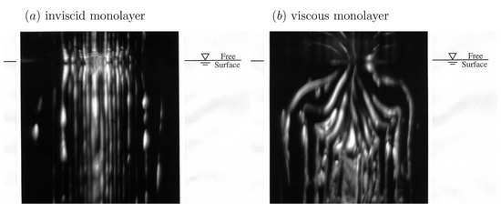
Figure 1.
Photographs of a columnar vortex at an air–water interface with (a) a low surface shear viscosity monolayer, oleyl alcohol, and (b) a relatively viscous monolayer, stearic acid. The length scale of the experiment is and the Reynolds number is . (Reproduced with permission from [50], published by AIP Publishing 1995).
Recently, a containerless biochemical reactor was introduced for the microgravity environment where containment is achieved by surface tension and shear is propagated primarily by the action of the surface shear viscosity [52,53,54,55]. Such a ring-sheared drop, shown schematically in Figure 2a, is driven by the rotation of a thin contact ring at some latitude in the top hemisphere along with a stationary ring in the bottom hemisphere. The ring-sheared drop was originally designed for the study of amyloid fibril formation aboard the International Space Station. Aside from mitigating settlement of aggregates in a microgravity environment, the ring-sheared drop minimizes complications associated with wall-nucleation during amyloidogenesis. Amyloid fibrils in flowing systems are widely studied since they are implicated in neurodegenerative diseases, including Parkinson’s and Alzheimer’s disease [56].
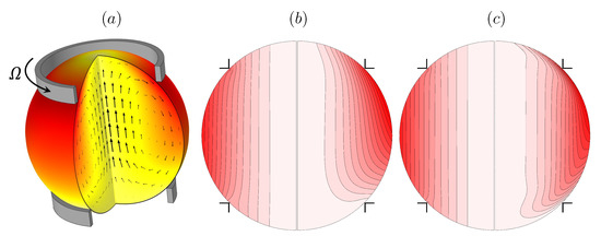
Figure 2.
(a) Schematic of the ring-sheared drop, and vortex lines in a meridional plane at (b) and (c) (in each, the left hemisphere is the flow at and the right at ). (Reproduced with permission from [52], published by American Physical Society 2019).
Numerical simulations of the flow in the ring-sheared drop, presented in Figure 2b,c, illustrate the effects of the surface shear viscosity on the vortex lines. For very small values of surface shear viscosity (quoted non-dimensionally as a Boussinesq number , where is the dynamic viscosity of the bulk drop liquid and R is the radius of the rings), the drop is essentially in solid-body rotation at the average angular velocity of the two rings; the vortex lines are essentially aligned with the rotation axis. On the other hand, for a large value of surface shear viscosity, corresponding to , the vortex lines show significant bending near the interface. A key observation is that surface viscosity does not directly affect the incidence angle of vortex lines at the interface, but rather it leads to a decelaration of the azimuthal flow component near the interface resulting in axial bending of the vortex lines, which in turn drives a secondary meridional flow [52]. The results shown in the figure are for Reynolds numbers and 103, where is the drop kinematic viscosity, further emphasizing that the effects of surface shear viscosity are not only manifested at small scales or low inertia.
3. Modeling the Non–Newtonian Interfacial Response
The simplest linear constitutive equation corresponding to a Newtonian interface is the Boussinesq–Scriven surface model (1). In regimes were the flow is axisymmetric, then the interfacial flow is purely shearing, the effects of surface dilatational viscosity are absent, Marangoni stress keeps the radial velocity zero, and the surface shear viscosity is the only surface property involved in the surface stress balance. In [36], the constitutive relation was generalized in order to model shear-thinning interfacial effects due to the presence of large macromolecules, such as proteins or densely-packed condensed-phase monolayers of phospholipids, by replacing with , which is the effective surface shear viscosity, a function of the magnitude of the local interfacial shear rate . The choice for the functional form of was motivated by the multiple reports of shear-thinning in DPPC films at high surface packing (corresponding to large surface pressure ) and its Newtonian response at low packing () [25,27,57], and inspired by the Sisko model in bulk (3D) rheology [58]:
where is the surface shear viscosity at very large shear rates, is the consistency index, and n is the power-law index. , , and n are material properties of the interface, and as such are only functions of the thermodynamic state of the material at the interface, i.e., the surface concentration c of the monolayer at a given temperature. DPPC is widely studied since it is the main constituent of lung surfactants, and also plays an important role in the bilayer that forms mammalian cell membranes.
4. Two-Way Coupled Flows
In order to gain a fundamental understanding of the two-way coupling between bulk and interfacial flows, it is desirable to keep the geometry as simple as possible, while allowing for a fully 3D unsteady bulk flow coupled to a nominally flat 2D unsteady and potentially non-Newtonian interface. Such a system is shown schematically in Figure 3, consisting of an open stationary cylinder filled to the brim with water, with a monolayer on the surface. The flow is driven by the constant rotation of the floor. When the floor is driven at a relatively low rotation rate , the bulk flow is axisymmetric. Fast rotation of the floor leads to fluid inertia causing instabilities breaking the symmetry, and the coupling between complex bulk flow and interface can be studied. This open cylinder flow is an idealization of many chemical and biological reactors and mixers, with the impeller/rotor replaced by the rotating floor [59,60]. The simplification afforded by this generic flow system allows us to focus on coupled hydrodynamics between the bulk and the interface without complications associated with the impeller/rotor, such as cavitation and 3D intricacies of the blade design. This flow geometry has been attracting some broad attention [61,62,63,64,65].
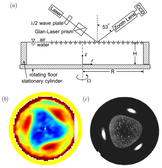
Figure 3.
(a) Schematic of the open cylinder flow system and Brewster angle microscopy (BAM) setup (reproduced with permission from [66], published by AIP Publishing 2002), (b) shear stress at the interface with a vitamin monolayer initially spread at , Reynolds number and (reproduced with permission from [20], published by AIP Publishing 2003), and (c) surface-bound polystyrene (21 m) at the same and (reproduced with permission from [21], published by American Chemical Society 2004).
In Figure 3, two different monolayers were used. One was a monomolecular film of vitamin , which is insoluble in water. The other was a single layer of micron-scale plastic particles (polystyrene) treated to be surface bound and scattered on the surface. Vitamin forms a well-behaved Langmuir film on water, with no noticeable hysteresis (surface tension vs. concentration measured in a Langmuir trough is identical during compressions and expansions), and no measurable surface viscosities. It only exhibits elasticity (Marangoni effect), which can be captured accurately with computations [17], or even simple analytic modeling [48]. The surface-bound polystyrene monolayer behaves as a fluid marker, with little or no elasticity until the particles are closely packed.
The bulk flow in the open cylinder system (Figure 3) is governed by the rotation rate of the floor, , the cylinder radius, R, and the kinematic viscosity of the bulk fluid (nominally water), . These combine to give the Reynolds number . The cylinder height-to-radius aspect ratio, , is also important—it determines how much of the shear introduced by the rotating floor reaches the surface. Then, of course, what material is on the surface also impacts the coupled flow, as was illustrated in a related problem in Figure 1. Regardless of whether it is clean or not, the deformability of the surface is governed by the Froude number , where g is the gravitational acceleration. For the experiment shown in Figure 3, , and the largest surface deformation was measured to be and the largest slope of the surface was [20]. For flows with larger aspect ratio , is even smaller and surface deformations will remain negligible. This flow with a nominally flat and clean interface has been studied experimentally and numerically [67], showing excellent agreement capturing the 3D instability. It is a bulk flow instability which is manifest at the interface. Figure 4 shows a direct comparison between the computed axial vorticity from 3D Navier–Stokes simulations and the experimentally measured axial vorticity using PIV, at mid-depth, together with isosurface plots of the computed perturbation velocity components.
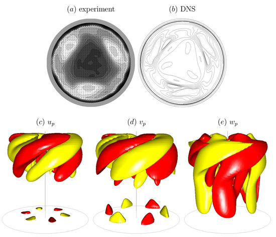
Figure 4.
Axial vorticity at mid-depth from (a) experimental PIV measurements and (b) 3D Navier–Stokes simulations, and (c–e) isosurfaces of the computed perturbation velocity components. (Reproduced with permission from [67], published by Cambridge University Press 2004.)
If the interface is not perfectly clean—which is generally the case with water no matter how pure the source or the container—then the flow can be drastically different. Surfactants generally reduce the surface tension. Gradients in the surfactant concentration result in surface tension gradients, i.e., Marangoni stresses. For a flat interface, there are no curvature effects and so the absolute value of surface tension is not dynamically important, but its gradients are and these must be balanced by viscous stresses in the bulk fluid evaluated at the interface. If the surfactant is viscous, it will also impart a viscous resistance on the interfacial flow, which must also be balanced by viscous stresses in the bulk fluid evaluated at the interface.
In the past we had focused on interfacial property measurements and so kept the flows as simple as possible. For example, to quantify the Marangoni stress or the surface shear viscosity, measurements and computations were done in an annular system, where the flow was driven fast enough to get a good signal-to-noise ratio, but not so fast as to break the axisymmetry [17,18]. We have also shown through experiments and computations that in oscillatory-driven axisymmetric flows, the phase lag between the oscillatory driving mechanism and interfacial velocity response can be fully accounted for by the coupling between interfacial and bulk flows, an effect that can be misinterpreted as a non-Newtonian interfacial response [29].
We have also studied non-Newtonian interfaces using axisymmetric flow to determine shear-thinning responses under steady conditions [36]. The non-Newtonian interface model (Section 3) was implemented and validated in the knife-edge flow geometry, consisting of a stationary open cylinder also filled with water to the brim, with a monolayer on the surface. A schematic is shown in Figure 5. The monolayer is sheared by the constant rotation of a circular knife edge of radius a and thickness , which just touches the interface. The model and experiments were able to access many regimes of non-Newtonian behavior. Interfacial azimuthal velocity profiles of DPPC at surface pressure over a range of and in the knife-edge flow geometry are shown in Figure 6. These were measured using particle tracking velocimetry. We found good agreement between model predictions and the measurements over two decades of and for flows in different aspect ratio containers.
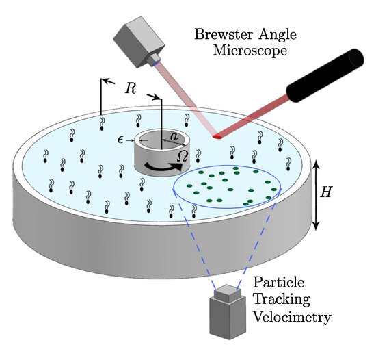
Figure 5.
Schematic of the knife-edge geometry and the experimental set-up. (Reproduced with permission from [36], published by American Physical Society 2018).
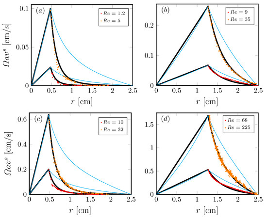
Figure 6.
Radial profiles of the azimuthal velocity at the interface in the knife-edge geometry (Figure 5) with with a DPPC monolayer at surface pressure ; (a,c) are driven by a knife edge of radius , (b,d) are driven by a knife edge of radius , at Reynolds number as indicated. The symbols correspond to experimental measurements, the thick black lines are the computed velocity profiles with the non-Newtonian model and the thin cyan lines are the computed Newtonian profiles. (Reproduced with permission from [36], published by American Physical Society 2018).
Figure 6 shows that the measured interfacial velocity profiles (symbols) at all and are clearly slower than the predicted Newtonian response (cyan curves). With the coupling to the bulk flow fully accounted for, this departure clearly shows the non-Newtonian nature of DPPC at this high . In contrast, the measured velocity profiles are in excellent agreement with predictions made by treating the interface as shear-thinning with a unique set of material properties [36]. Perhaps more importantly, the results show that the effective surface shear viscosity is modeled consistently over a range of six decades in shear rate variation, as shown in Figure 7. Those results also show that we were able to recover measurements by Hermans and Vermant [57] for the same monolayer but in a different flow geometry. In [36], the viscous response of the entire interfacial flow field was measured and matched against computed interfacial velocity using our non-Newtonian interfacial model to determine interfacial properties, in contrast to the typical practice of using a local estimate of the imposed shear. This allowed us to explore global/macroscopic effects of the imposed shear to quantify interfacial properties.
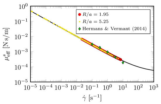
Figure 7.
Effective measured viscosity of DPPC monolayer at surface pressure , determined from the experimental interfacial velocity profiles shown in Figure 6. The black curve computed from the non-Newtonian model [36], and the green diamond symbols are data from [57] taken in a double-wall ring apparatus with DPPC at . (Reproduced with permission from [36], published by American Physical Society 2018).
5. Marangoni Effects
In the previous section, interfacial flows were considered where the monolayer concentration remained uniform, and hence the Maragoni stress was zero, in order to isolate the effects of interfacial shear viscosity. In this section, we consider interfacial flows that drive surfactant concentration gradients and hence have non-zero Marangoni stress. Monolayers of vitamin are particularly useful to ellucidate these as they have essentially zero surface shear viscosity.
The deep-channel surface viscometer, schematically depicted in Figure 8, provides a sensitive means for determination of the surface shear viscosity when the radial component of the surface flow is negligible, i.e., is sufficiently small [68]. At large , where inertia is dominant, the channel can be utilized for the study of Marangoni elasticity, namely the balance between the surface tension gradient and liquid stress evaluated at the surface. A strong secondary flow is generated by the rotation of the floor, driving the fluid out radially in the rotating floor boundary layer. This radial boundary layer flow is turned up along the outer cylinder, which then turns inward at the surface. Measurements of the radially inward flow at the free surface in a relatively large annular channel, with outer radius and inner radius , are shown in Figure 9a. The initial (uniform) concentration of a vitamin monolayer was varied. At sufficiently small initial concentrations, the radial inward flow near the surface is strong enough to completely clear the outer region of the flow and compress the monolayer toward the inner cylinder. Numerical simulations using the equation-of-state, measured in a Langmuir trough, provide surprisingly good agreement with the experiments (Figure 9b), especially in light of the fact that the capillary number, , is very small for the experiments with water at that scale. The small makes the results very sensitive to the details in the equation-of-state. The main discrepancy is that with an initial concentration mg/m, the simulations predict that the monolayer cannot be completely cleared near the outer cylinder, whereas in the experiments that limit is mg/m.
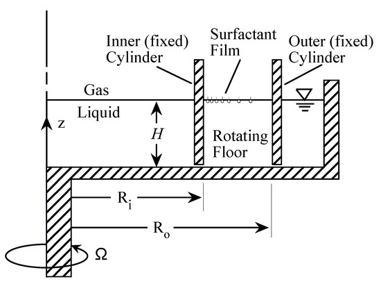
Figure 8.
Schematic of the deep-channel surface viscometer.
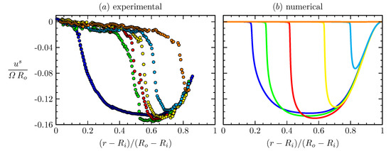
Figure 9.
Radial profiles of the radial velocity at the interface, over the annular gap measured in a deep-channel surface viscometer (Figure 8), (a) experimentally measured via boundary-fitted PIV at steady state for initial vitamin monolayer surface concentrations: (blue), mg/m (green), mg/m (red), mg/m (yellow), mg/m (cyan), mg/m (orange), at Reynolds number , together with (b) the corresponding numerical profiles at nominally the same and . Note that the blue numerical profile corresponds to mg/m, suggesting that there are some residual surfactants in the experiments without a monolayer being added. (Reproduced with permission from [17], published by Cambridge University Press 2001).
6. Surface Dilatational Viscosity and Non-Equilibrium Monolayer State
Surface tension is a well-defined equilibrium quantity. It is commonly measured quasi-statically using a Langmuir trough, and is used successfully in static equilibrium problems. Shear viscosity has also been consistently measured by a variety of techniques, all of them implemented at steady state [18,47,68]. Oscillatory sheared monolayers can also be treated via equilibrium interfacial rheology provided that the bulk flow inertia is accounted for in the interfacial stress balance, and the monolayer concentration remains essentially uniform [29].
The situation with dilatational viscosity is much more complicated; its measurement using techniques with different time scales for the surface strain varies by as much as a factor of for a given surfactant [69]. In a compressing or dilating interfacial flow, the time scale for the flow process is usually different from the time scales associated with monolayer equilibration. Thus, resistance to compression or dilation as predicted using equilibrium surface tension gradients may not be reconciled with the resultant stress. In fact, there have been several reports of apparent negative surface dilatational viscosity measurements [33,70,71,72,73,74,75,76,77,78]. Negative viscosity is physically inconsistent as it violates the second law of thermodynamics, and some have conjectured this anomaly to be due to monolayer phase behavior [33,75], but it remains a hotly debated issue [79,80,81].
Usually, the equation-of-state is measured by spreading a uniform monolayer on a Langmuir trough, allowing it to equilibriate for a long time and then subjecting it to a quasi-static compression and/or expansion and measuring the surface tension (using a Wilhelmy plate) as a function of monolayer concentration, giving the equation-of-state. However, if the monolayer is first forced, for example by shearing, then the resultant equation-of-state is found to be different because the monolayer phase morphology is different [82]. The point is that for continuously compressed and expanded monolayers, finding the equation-of-state for a freshly spread static monolayer is not what is needed. It is the thermodynamic properties (surface tension and surface viscosities) of the monolayer in its morphological state under oscillatory dilatational flow that are needed.
7. Conclusions
Interfacial systems that have focused on modeling and measuring their rheological properties [37] have been such that the bulk flow is generally in the inertialess Stokes flow regime. In those cases, the role of the bulk flow is merely to support the interfacial film. The challenge is what happens when the bulk flows are hydrodynamically important, e.g., when inertia is not negligible. Although the bulk flow is generally still incompressible, the interfacial flow is not divergence-free. Sagis [83] discusses how to treat dilating interfaces, but the challenge remains how to couple these interfacial flows to hydrodynamically important and inertia-dominated bulk flows. When one is growing a micro-organism, such as E. coli, as part of vaccine manufacturing to inoculcate billions of people or producing huge quantities of monoclonal antibodies to treat hundreds of millions of people, large systems are utilized. Such biochemical reactors, with thousands of liters of flowing liquid, are undoubtedly inertia-dominated flows.
Author Contributions
Both authors contributed equally. All authors have read and agreed to the published version of the manuscript.
Funding
This research was funded by NASA grant NNX13AQ22G and NSF grants 1929134 and 1929139.
Institutional Review Board Statement
Not applicable.
Informed Consent Statement
Not applicable.
Data Availability Statement
Not applicable.
Conflicts of Interest
The authors declare no conflict of interest.
References
- Notter, R.H. Lung Surfactants: Basic Science and Clinical Applications; Lung Biology in Health and Disease; Marcel Dekker: New York, NY, USA, 2000; Volume 149. [Google Scholar]
- Frew, N.M. The role of organic films in air–sea gas exchange. In The Sea Surface and Global Change; Liss, P.S., Duce, R.A., Eds.; Cambridge University Press: Cambridge, UK, 1997; Chapter 5; pp. 121–171. [Google Scholar]
- Tsai, W.T.; Liu, K.K. An assessment of the effect of sea surface surfactant on global atmosphere-ocean CO2 flux. J. Geophys. Res. 2003, 108, 3127. [Google Scholar] [CrossRef]
- Lee, R.J.; Saylor, J.R. The effect of a surfactant monolayer on oxygen transfer across an air/water interface during mixed convection. Int. J. Heat Mass Transf. 2010, 53, 3405–3413. [Google Scholar] [CrossRef]
- Salter, M.E.; Upstill-Goddard, R.C.; Nightingale, P.D.; Archer, S.D.; Blomquist, B.; Ho, D.T.; Huebert, B.; Schlosser, P.; Yang, M. Impact of an artificial surfactant release on air–sea gas fluxes during Deep Ocean Gas Exchange Experiment II. J. Geophys. Res. 2011, 116, C11016. [Google Scholar] [CrossRef]
- Zhang, X.D.; Macosko, C.W.; Davis, H.T.; Nikolov, A.D.; Wasan, D.T. Role of silicone surfactant in flexible polyurethane foam. J. Colloid Interface Sci. 1999, 215, 270–279. [Google Scholar] [CrossRef] [PubMed]
- Snow, S.A.; Pernisz, U.C.; Braun, R.J. “Tying up loose ends”—silicone surfactants as stabilizing agents for flexible polyurethane foam. Silicon Chem. 2005, 3, 1–10. [Google Scholar] [CrossRef]
- Li, J.; Krause, M.E.; Chen, X.; Cheng, Y.; Dai, W.; Hill, J.J.; Huang, M.; Jordan, S.; LaCasse, D.; Narhi, L.; et al. Interfacial Stress in the Development of Biologics: Fundamental Understanding, Current Practice, and Future Perspective. AAPS J. 2019, 21, 44. [Google Scholar] [CrossRef] [PubMed]
- Kuehn, S. Pharmaceutical manufacturing: Current trends and what is next. Chem. Eng. Prog. 2018, 114, 23–29. [Google Scholar]
- Rathore, N.; Rajan, R.S. Current perspectives on stability of protein drug products during formulation, fill and finish operations. Biotechnol. Prog. 2008, 24, 504–514. [Google Scholar] [CrossRef]
- Rathore, N.; Rajan, R.S.; Freund, E. Impact of manufacturing processes on drug product stability and quality. In Formulation and Development Strategies for Manufacturing Biopharmaceuticals; Jameel, F., Hershenson, S., Eds.; John Wiley & Sons: Hoboken, NJ, USA, 2010. [Google Scholar]
- Gikanga, B.; Hui, A.; Maa, Y.F. Mechanistic Investigation on Grinding-Induced Subvisible Particle Formation during Mixing and Filling of Monoclonal Antibody Formulations. PDA J. Pharm. Sci. Tech. 2018, 72, 117–133. [Google Scholar] [CrossRef]
- Nejadnik, M.R.; Randolph, T.W.; Volkin, D.B.; Schöneich, C.; Carpenter, J.F.; Crommelin, D.J.A.; Jiskoot, W. Postproduction Handling and Administration of Protein Pharmaceuticals and Potential Instability Issues. J. Pharm. Sci. 2018, 107, 2013–2019. [Google Scholar] [CrossRef]
- Tryggvason, G.; Scardovelli, R.; Zaleski, S. Direct Numerical Simulations of Gas-Liquid Multiphase Flows; Cambridge University Press: Cambridge, UK, 2011. [Google Scholar]
- Lopez, J.M.; Hirsa, A. Direct determination of the dependence of the surface shear and dilatational viscosities on the thermodynamic state of the interface: Theoretical foundations. J. Colloid Interface Sci. 1998, 206, 231–239. [Google Scholar] [CrossRef]
- Lopez, J.M.; Hirsa, A. Surfactant influenced gas/liquid interfaces: Nonlinear equation of state and finite surface viscosities. J. Colloid Interface Sci. 2000, 229, 575–583. [Google Scholar] [CrossRef] [PubMed]
- Hirsa, A.H.; Lopez, J.M.; Miraghaie, R. Measurement and computation of hydrodynamic coupling at an air/water interface in the presence of an insoluble monolayer. J. Fluid Mech. 2001, 443, 271–292. [Google Scholar] [CrossRef]
- Hirsa, A.H.; Lopez, J.M.; Miraghaie, R. Determination of surface shear viscosity via deep-channel flow with inertia. J. Fluid Mech. 2002, 470, 135–149. [Google Scholar] [CrossRef][Green Version]
- Lopez, J.M.; Miraghaie, R.; Hirsa, A.H. Non-Newtonian behavior of an insoluble monolayer: Effects of inertia. J. Colloid Interface Sci. 2002, 248, 103–110. [Google Scholar] [CrossRef][Green Version]
- Miraghaie, R.; Lopez, J.M.; Hirsa, A.H. Flow induced patterning at the air/water interface. Phys. Fluids 2003, 15, L45–L48. [Google Scholar] [CrossRef]
- Vogel, M.J.; Miraghaie, R.; Lopez, J.M.; Hirsa, A.H. Flow-induced patterning of Langmuir monolayers. Langmuir 2004, 20, 5651–5654. [Google Scholar] [CrossRef]
- Hirsa, A.H.; Lopez, J.M.; Vogel, J.M.; Leung, J.F.F. Effects of shearing flow with inertia on monolayer mesoscale structure. Langmuir 2006, 22, 9483–9486. [Google Scholar] [CrossRef]
- Azadani, A.N.; Lopez, J.M.; Hirsa, A.H. Protein crystallization at the air/water interface induced by shearing bulk flow. Langmuir 2007, 23, 5227–5230. [Google Scholar] [CrossRef]
- Azadani, A.N.; Lopez, J.M.; Hirsa, A.H. Coupling between protein-laden films and a shearing bulk flow. J. Colloid Interface Sci. 2008, 322, 79–86. [Google Scholar] [CrossRef]
- Sadoughi, A.H.; Lopez, J.M.; Hirsa, A.H. Transition from Newtonian to non-Newtonian surface shear viscosity of phospholipid monolayers. Phys. Fluids 2013, 25, 032107. [Google Scholar] [CrossRef]
- Lopez, J.M.; Hirsa, A.H. Coupling of the interfacial and bulk flow in knife-edge viscometers. Phys. Fluids 2015, 27, 042102. [Google Scholar] [CrossRef]
- Raghunandan, A.; Lopez, J.M.; Hirsa, A.H. Bulk flow driven by a viscous monolayer. J. Fluid Mech. 2015, 785, 283–300. [Google Scholar] [CrossRef]
- McBride, S.A.; Sanford, S.P.; Lopez, J.M.; Hirsa, A.H. Shear-induced amyloid fibrillization: Role of inertia. Soft Matter 2016, 12, 3461–3467. [Google Scholar] [CrossRef] [PubMed]
- Rasheed, F.; Raghunandan, A.; Hirsa, A.H.; Lopez, J.M. Oscillatory shear rheology measurements and Newtonian modeling of insoluble monolayers. Phys. Rev. Fluids 2017, 2, 044002. [Google Scholar] [CrossRef]
- Balaraj, V.S.; Zeng, P.C.; Sanford, S.P.; McBride, S.A.; Raghunandan, A.; Lopez, J.M.; Hirsa, A.H. Surface shear viscosity as a macroscopic probe of amyloid fibril formation at a fluid interface. Soft Matter 2017, 13, 1780–1787. [Google Scholar] [CrossRef]
- Lopez, J.M.; Hirsa, A. Oscillatory driven cavity with an air/water interface and an insoluble monolayer: Surface viscosity effects. J. Colloid Interface Sci. 2001, 242, 1–5. [Google Scholar] [CrossRef][Green Version]
- Vogel, M.J.; Hirsa, A.H.; Lopez, J.M. Spatio-temporal dynamics of a periodically driven cavity flow. J. Fluid Mech. 2003, 478, 197–226. [Google Scholar] [CrossRef][Green Version]
- Lopez, J.M.; Vogel, M.J.; Hirsa, A.H. Influence of co-existing phases on the surface dilatational viscosity of Langmuir monolayers. Phys. Rev. E 2004, 70, 056308. [Google Scholar] [CrossRef]
- Leung, J.J.F.; Hirsa, A.H.; Blackburn, H.M.; Marques, F.; Lopez, J.M. Three-dimensional modes in a periodically driven elongated cavity. Phys. Rev. E 2005, 71, 026305. [Google Scholar] [CrossRef]
- Underhill, P.; Hirsa, A.H.; Lopez, J.M. Modeling steady shear flows of Newtonian liquids with non-Newtonian interfaces. J. Fluid Mech. 2017, 814, 5–23. [Google Scholar] [CrossRef]
- Raghunandan, A.; Hirsa, A.H.; Underhill, P.T.; Lopez, J.M. Predicting steady shear rheology of condensed-phase monomolecular films at the air-water interface. Phys. Rev. Lett. 2018, 121, 164502. [Google Scholar] [CrossRef] [PubMed]
- Jaensson, N.O.; Anderson, P.D.; Vermant, J. Computational interfacial rheology. J. Non–Newton. Fluid Mech. 2021, 290, 104507. [Google Scholar] [CrossRef]
- Patouillet, K.; Davoust, L.; Doche, O.; Delacroix, J. Mannheimer and Schechter model revisited: Viscosimetry of a (non-)Newtonian and curved interface. Phys. Rev. Fluids 2019, 4, 054002. [Google Scholar] [CrossRef]
- Stebe, K.; Lin, S.; Maldaralli, C. Remobilizing surfactant retarded fluid particle interfaces. I. Stress-free conditions at the interfaces of micellar solutions of surfactants with fast adsorption kinetics. Phys. Fluids A 1991, 3, 3–20. [Google Scholar] [CrossRef]
- Chang, C.; Franses, E. Adsorption dynamics of surfactants at the air/water interface: A critical review of mathematical models, data, and mechanisms. Colliods Surfaces A 1995, 100, 1–45. [Google Scholar] [CrossRef]
- Zell, Z.A.; Nowbahar, A.; Mansard, V.; Leal, L.G.; Deshmukh, S.S.; Mecca, J.M.; Tucker, C.J.; Squires, T.M. Surface shear inviscidity of soluble surfactants. Proc. Natl. Acad. Sci. USA 2014, 111, 3677–3682. [Google Scholar] [CrossRef]
- Manikantan, H.; Squires, T. Surfactant dynamics: Hidden variables controlling fluid flows. J. Fluid Mech. 2020, 100, P1. [Google Scholar] [CrossRef]
- Slattery, J.C.; Sagis, L.; Oh, E.S. Interfacial Transport Phenomena, 2nd ed.; Springer: New York, NY, USA, 2007. [Google Scholar]
- Scriven, L.E. Dynamics of a fluid interface. Chem. Engng. Sci. 1960, 12, 98–108. [Google Scholar] [CrossRef]
- Chen, J. Hydrodynamic Coupling between a Viscoelastic Gas/Liquid Interface and a Swirling Vortex Flow. Ph.D. Thesis, The Pennsylvania State University, State College, PA, USA, 1998. [Google Scholar]
- Lopez, J.M.; Chen, J. Coupling between a viscoelastic gas/liquid interface and a swirling vortex flow. J. Fluids Eng. 1998, 120, 655–661. [Google Scholar] [CrossRef]
- Jiang, T.S.; Chen, J.D.; Slattery, J.C. Nonlinear interfacial stress-deformation behavior measured with several interfacial viscometers. J. Colloid Interface Sci. 1983, 96, 7–19. [Google Scholar] [CrossRef]
- Vogel, M.J.; Hirsa, A.H. Concentration measurements downstream of an insoluble monolayer front. J. Fluid Mech. 2002, 472, 283–305. [Google Scholar] [CrossRef]
- Espinosa, G.; López-Montero, I.; Monroy, F.; Langevin, D. Shear rheology of lipid monolayers and insights on membrane fluidity. Proc. Natl. Acad. Sci. USA 2011, 108, 6008–6013. [Google Scholar] [CrossRef] [PubMed]
- Hirsa, A.; Harper, J.E.; Kim, S. Columnar vortex generation and interaction with a clean or contaminated free surface. Phys. Fluids 1995, 7, 2532–2534. [Google Scholar] [CrossRef]
- Hirsa, A.; Lopez, J.M.; Kim, S. Evolution of an initially columnar vortex terminating normal to a no-slip wall. Expts. Fluids 2000, 29, 309–321. [Google Scholar] [CrossRef]
- Gulati, S.; Riley, F.P.; Hirsa, A.H.; Lopez, J.M. Flow in a containerless liquid system: Ring-sheared drop with finite surface shear viscosity. Phys. Rev. Fluids 2019, 4, 044006. [Google Scholar] [CrossRef]
- Gulati, S.; Riley, F.P.; Lopez, J.M.; Hirsa, A.H. Mixing within drops via surface shear viscosity. Int. J. Heat Mass Transf. 2018, 125, 559–568. [Google Scholar] [CrossRef]
- McMackin, P.M.; Griffin, S.R.; Riley, F.P.; Gulati, S.; Debono, N.E.; Raghunandan, A.; Lopez, J.M.; Hirsa, A.H. Simulated microgravity in the ring-sheared drop. Npj Microgravity 2020, 6, 2. [Google Scholar] [CrossRef]
- Riley, F.P.; McMackin, P.M.; Lopez, J.M.; Hirsa, A.H. Flow in a ring-sheared drop: Drop deformation. Phys. Fluids 2021, 33, 042117. [Google Scholar] [CrossRef]
- Dobson, C. Protein misfolding, evolution and disease. Trends Biochem. Sci. 1999, 24, 329–332. [Google Scholar] [CrossRef]
- Hermans, E.; Vermant, J. Interfacial shear rheology of DPPC under physiologically relevant conditions. Soft Matter 2014, 10, 175–186. [Google Scholar] [CrossRef] [PubMed]
- Sisko, A.W. The flow of lubricating greases. Ind. Eng. Chem. 1958, 50, 1789–1792. [Google Scholar] [CrossRef]
- Neitzel, G.P. Bioreactor fluid dynamics. In Proceedings of the 4th AIAA Theoretical Fluid Mechanics Meeting, Toronto, ON, Canada, 6–9 June 2005. [Google Scholar]
- Dusting, J.; Sheridan, J.; Hourigan, K. A fluid dynamics approach to bioreactor design for cell and tissue culture. Biotechnol. Bioeng. 2006, 94, 1196–1208. [Google Scholar] [CrossRef] [PubMed]
- Spohn, A.; Mory, M.; Hopfinger, E.J. Observations of vortex breakdown in an open cylindrical container with a rotating bottom. Expt. Fluids 1993, 14, 70–77. [Google Scholar] [CrossRef]
- Brons, M.; Voigt, L.K.; Sorensen, J.N. Topology of vortex breakdown bubbles in a cylinder with a rotating bottom and a free surface. J. Fluid Mech. 2001, 428, 133–148. [Google Scholar] [CrossRef]
- Serre, E.; Bontoux, P. Vortex breakdown in a cylinder with a rotating bottom and a flat stress-free surface. Int. J. Heat Fluid Flow 2007, 28, 229–248. [Google Scholar] [CrossRef]
- Cogan, S.J.; Ryan, K.; Sheard, G.J. Symmetry breaking and instability mechanisms in medium depth torsionally driven open cylinder flows. J. Fluid Mech. 2011, 672, 521–544. [Google Scholar] [CrossRef]
- Yang, W.; Delbende, I.; Fraigneau, Y.; Witkowski, L.M. Axisymmetric rotating flow with free surface in a cylindrical tank. J. Fluid Mech. 2019, 861, 796–814. [Google Scholar] [CrossRef]
- Hirsa, A.H.; Lopez, J.M.; Miraghaie, R. Symmetry breaking to a rotating wave in a lid-driven cylinder with a free surface: Experimental observation. Phys. Fluids 2002, 14, L29–L32. [Google Scholar] [CrossRef]
- Lopez, J.M.; Marques, F.; Hirsa, A.H.; Miraghaie, R. Symmetry breaking in free-surface cylinder flows. J. Fluid Mech. 2004, 502, 99–126. [Google Scholar] [CrossRef]
- Mannheimer, R.J.; Schechter, R.S. An improved apparatus and analysis for surface rheological measurements. J. Colloid Interface Sci. 1970, 32, 195–211. [Google Scholar] [CrossRef]
- Kao, R.L.; Edwards, D.A.; Wasan, D.T.; Chen, E. Measurement of interfacial dilatational viscosity at high rates of interface expansion using the maximum bubble pressure method. I. Gas-liquid surface. J. Colloid Interface Sci. 1992, 148, 247–256. [Google Scholar] [CrossRef]
- Sharp, D.; Eastoe, J. Properties of surfactant monolayers studied by surface light scattering. Langmuir 1996, 12, 2303–2307. [Google Scholar] [CrossRef]
- Peace, S.K.; Richards, R.W. Capillary wave fluctuations of spread films of an amphiphilic graft copolymer at the air-water interface. Polymer 1996, 37, 4945–4951. [Google Scholar] [CrossRef]
- Sharp, D.; Earnshaw, J.C. Surface viscoelastic relation on aqueous solutions of tetradyrofuran. J. Chem. Phys. 1997, 107, 7493–7501. [Google Scholar] [CrossRef]
- Peace, S.K.; Richards, R.W. Surface quasi-elastic light scattering from an amphiphilic graft copolymer at the air-water interface. Langmuir 1998, 14, 667–678. [Google Scholar] [CrossRef]
- Monroy, F.; Giermanska-Kahn, J.; Langevin, D. Dilational viscoelasticity of surfactant monolayers. Colloids Surfaces A Physicochem. Engin. Asp. 1998, 143, 251–260. [Google Scholar] [CrossRef]
- Giermanska-Kahn, J.; Monroy, F.; Langevin, D. Negative effective surface viscosities in insoluble fatty acid monolayers: Effects of phase transition on dilatational viscoelasticity. Phys. Rev. E 1999, 60, 7163–7173. [Google Scholar] [CrossRef]
- Monroy, F.; Giermanska-Kahn, J.; Langevin, D. Anomalous damping of capillary waves with surfactant solutions. J. Non-Equilib. Thermodyn. 2000, 25, 279–299. [Google Scholar] [CrossRef]
- He, P.; Fang, K.; Zou, G.; Peltonen, J.P.K.; Rosenholm, J.B. Elasticity of Langmuir monolayer detected by dynamic oscillation method. Colloids Surfaces A Physicochem. Engin. Asp. 2002, 201, 265–273. [Google Scholar] [CrossRef]
- Monroy, F.; Munoz, M.G.; Rubio, J.E.F.; Ortega, F.; Rubio, R.G. Capillary waves in ionic surfactant solutions: Effects of the electrostatic adsorption barrier and analysis in terms of a new dispersion equation. J. Phys. Chem. B 2002, 106, 5636–5644. [Google Scholar] [CrossRef]
- Buzza, D.M.A.; Jones, J.L.; McLeish, T.C.B.; Richards, R.W. Theory of surface light scattering from a fluid-fluid interface with adsorbed polymeric surfactants. J. Chem. Phys. 1998, 109, 5008–5024. [Google Scholar] [CrossRef]
- Noskov, B.A.; Loglio, G. Dynamic surface elasticity of surfactant solutions. Colloids Surf. A Physicochem. Engin. Asp. 1998, 143, 167–183. [Google Scholar] [CrossRef]
- Munoz, M.G.; Monroy, F.; Hernandez, P.; Ortega, F.; Rubio, R.G.; Langevin, D. Anomalous damping of the capillary waves at the air-water interface of a soluble triblock copolymer. Langmuir 2003, 19, 2147–2154. [Google Scholar] [CrossRef]
- Alonso, C.; Waring, A.; Zasadzinski, J.A. Keeping lung surfactant where it belongs: Protein regulation of two-dimensional viscosity. Biophys. J. 2005, 89, 266–273. [Google Scholar] [CrossRef]
- Sagis, L.M.C. Dynamic properties of interfaces in soft matter: Experiments and theory. Rev. Mod. Phys. 2011, 83, 1367–1403. [Google Scholar] [CrossRef]


Publisher’s Note: MDPI stays neutral with regard to jurisdictional claims in published maps and institutional affiliations. |
© 2021 by the authors. Licensee MDPI, Basel, Switzerland. This article is an open access article distributed under the terms and conditions of the Creative Commons Attribution (CC BY) license (https://creativecommons.org/licenses/by/4.0/).