Article

The Lifetimes of Evaporating Sessile Droplets of Water Can Be Strongly Influenced by Thermal Effects

by
Feargus G. H. Schofield
1,
David Pritchard
1,
Stephen K. Wilson
1,* and
Khellil Sefiane
2
1
Department of Mathematics and Statistics, University of Strathclyde, 26 Richmond Street, Glasgow G1 1XH, Scotland, UK
2
Institute for Multiscale Thermofluids, School of Engineering, The University of Edinburgh, James Clerk Maxwell Building, Peter Guthrie Tait Road, The King’s Buildings, Edinburgh EH9 3FD, Scotland, UK
*
Author to whom correspondence should be addressed.
Fluids 2021, 6(4), 141; https://doi.org/10.3390/fluids6040141
Submission received: 26 February 2021 / Revised: 28 March 2021 / Accepted: 30 March 2021 / Published: 3 April 2021
(This article belongs to the Special Issue Dynamics of Droplets and Bubbles)

Abstract

:
The effect of the thermal properties of the system on the lifetime of an evaporating sessile droplet of water is analysed using a fully coupled model which involves determining the temperature of the droplet, the substrate and the atmosphere. The evolutions, and hence the lifetimes, of droplets of water evaporating in both of the extreme modes are calculated. In particular, it is shown how the lifetimes of droplets of water can be strongly influenced by thermal effects. Droplets with larger initial contact angles or on less conductive substrates generally have longer lifetimes than those with smaller initial contact angles or on more conductive substrates, and the physical mechanism by which the thermal properties of the system influence the evaporation can be understood in terms of the thermal anchoring between the droplet and the lower surface of the substrate.

Graphical Abstract

1. Introduction

The evaporation of sessile droplets is a fundamental scientific problem that is key to numerous physical and biological processes, including a wide range of industrial applications such as the agrochemical spraying of plants, DNA analysis and the manufacture of OLED displays, and has been the subject of an explosion of analytical, experimental, and numerical investigations in recent years (see, for example, the review articles by Larson [1], Brutin and Starov [2], and Giorgiutti-Dauphiné and Pauchard [3]).
A key challenge is to determine the lifetime of a droplet and how it depends on both what mode of evaporation the droplet is undergoing and the physical properties of the system (see, for example, [4,5,6,7,8,9,10,11,12,13,14,15,16]). In particular, since, in general, the evaporation rate of a droplet depends on its temperature, which in turn depends on the thermal properties of the system, the lifetime of a droplet will, in general, depend on thermal effects (see, for example, [14,15,17,18,19,20,21,22,23,24]). However, the manner in which it does so remains an open question.
More than a decade ago, Dunn et al. [18] demonstrated, both experimentally and theoretically, the strong influence of the thermal conductivity of the substrate on the evaporation rate of a sessile droplet. They used a partially coupled model which assumed the atmosphere to be isothermal, and focused on the initial evaporation rate of droplets with pinned contact lines. They did not, however, attempt to calculate the lifetimes of the droplets. In an important contribution, Ait Saada et al. [22] employed a fully coupled model which involved determining the (in general, non-uniform) temperature of the atmosphere, and calculated the complete evolutions of droplets of water evaporating in both extreme modes (i.e., the constant contact radius and constant contact angle modes). However, they only considered a single value of the initial contact angle, and so did not investigate the dependence of the lifetimes of the droplets on this parameter. On the other hand, Stauber et al. [9,10] considered a decoupled model in which the evaporation rate of the droplet is independent of thermal effects, and gave a complete description of the dependence of the lifetimes of droplets evaporating in the extreme modes and the stick–slide mode on the initial contact angle. However, their analysis was, of course, unable to give any information about the dependence of the lifetimes of the droplets on thermal effects. More recently, Schofield et al. [14] used a limiting case of the fully coupled model to obtain analytical expressions for the evolutions, and hence the lifetimes, of droplets evaporating in the extreme modes, the stick–slide mode and the stick–jump mode. However, their analysis was restricted to the distinguished asymptotic limit of thin droplets on thin substrates with strong thermal effects and, in particular, to small initial contact angles.
In the present work we build on these previous studies to give a detailed account of the effect of the thermal properties of the system (and, in particular, the thermal conductivity of the substrate) on the lifetime of an evaporating sessile droplet of water for the full range of initial contact angles using the fully coupled model. Specifically, in Section 2 we describe the fully coupled model and its numerical implementation, in Section 3 we investigate the temperature and vapour concentration fields in order to elucidate the physical mechanism controlling evaporation, in Section 4 we present results for the lifetime of a droplet of water in various conditions, and in Section 5 we summarise our results and suggest some directions for future work.

2. The Fully Coupled Model

2.1. Governing Equations and Boundary Conditions

We consider a small droplet (i.e., a droplet with small Bond–Eötvös number) whose free surface takes the form of a spherical cap with radius R , contact angle θ , and contact radius R = R sin θ . Working in cylindrical polar co-ordinates with the origin on the substrate z = 0 at the centre of the droplet–substrate interface, the free surface of the droplet can be written as
z = h ( r , t ) = R cos θ ± R 2 r 2 ,
and its volume is given by
V ( t ) = π R 3 sin θ ( 2 + cos θ ) 3 ( 1 + cos θ ) 2 ,
where t denotes time.
We treat the evaporation as a quasi-static process in a quiescent atmosphere, neglecting both adjustment times and convective vapour and heat transfer. These assumptions are reasonable for relatively slowly evaporating liquids such as water, but may not always hold for more volatile liquids such as methanol (for further details, see Schofield [25]). Under these assumptions the temperature fields in the droplet, the substrate and the atmosphere, denoted by T ( r , z , t ) , T s ( r , z , t ) and T a ( r , z , t ) , respectively, all satisfy Laplace’s equation. The temperature and heat flux are continuous across the droplet–substrate and atmosphere–substrate interfaces, and a constant far-field temperature T is imposed far from the droplet in both the atmosphere and the substrate. The same temperature is imposed on the lower surface of the substrate, z = h s , where h s is the thickness of the substrate.
We employ the standard diffusion-limited model of evaporation (see, for example, [4,18,26,27]), in which the vapour concentration field in the atmosphere, denoted by c ( r , z , t ) , also satisfies Laplace’s equation. On the free surface of the droplet, z = h , the heat and evaporative mass fluxes are related by the energy balance equation
k a T a k T · n = L D c · n = L J ,
where k, k s and k a are the thermal conductivities of the droplet, the substrate and the atmosphere, respectively, n is the local outward normal to the surface, L is the latent heat of vaporisation, D is the diffusion coefficient of vapour in the atmosphere, and J ( r , t ) is the (spatially and temporally non-uniform) evaporative mass flux. The vapour concentration at the surface of the droplet is given by the local saturation concentration,
c = c sat ( T ) ,
which is a prescribed decreasing function of temperature (see Section 2.3). Finally, in the atmosphere far from the droplet the vapour concentration approaches a constant value c = H c sat ( T ) , where H ( 0 H 1 ) is the relative saturation in the far field.
As already mentioned, like many other previous authors, Stauber et al. [9,10] considered a simplified version of the present model in which c sat is assumed to be independent of T. While the system is not isothermal according to this decoupled model (i.e., evaporative cooling of the droplet and its surroundings still occurs), it does mean that the evolution, and hence the lifetime, of the droplet are independent of thermal effects. The decoupled model is a limiting case of the present fully coupled model and, since c sat is a decreasing function of temperature, it provides an upper bound on the evaporation rate, and hence a lower bound on the lifetime of a droplet. This result will be confirmed by the numerically calculated lifetimes presented in Section 4. In contrast, in their partially coupled model Dunn et al. [18] allowed c sat to depend on T, but assumed that the atmosphere is isothermal, and did not impose either continuity of temperature across the free surface of the droplet or continuity of heat flux across the atmosphere–substrate interface. The partially coupled model used by Dunn et al. [18] is therefore not a limiting case of the present fully coupled model. We will return to this point in Section 2.2.
We consider the two extreme modes of evaporation, namely the constant contact radius (CR) mode in which R is fixed and θ decreases over time, and the constant contact angle (CA) mode in which θ is fixed and R decreases over time (see, for example, [4,9,10]). We note that a variety of other modes of evaporation, such as the stick–slide mode and the stick–jump mode, may also occur (see, for example, [5,6,7,8,9,10,12,13,14]), but these are not considered in the present work.

2.2. Numerical Implementation and Validation

Quasi-steady solutions for the temperature and concentration fields were obtained numerically at each timestep using a finite-element method implemented using COMSOL Multiphysics 5.4 [28]. A large but finite domain, typically 300 to 400 times the radius of the droplet, was employed and was discretised using a free triangular mesh generated using the meshing tools provided within COMSOL Multiphysics. In order to accurately resolve the behaviour of the evaporative flux near the contact line, the resolution of the mesh was greatly increased within a small circular subdomain centered on the contact line. A typical build of the mesh contained 10 5 domain elements and 10 3 boundary elements, and the dependence on the domain size and mesh resolution was less than 0.5 % . Obtaining the quasi-steady solutions (including building the mesh) typically took around 30 s on a standard desktop computer. Further details of the numerical implementation are given by Schofield [25].
From the quasi-steady solution at the ith timestep, with volume V = V i , the total evaporative flux from the droplet, and thus the rate of change of the volume at that timestep, V ˙ i , were calculated, and the volume at the ( i + 1 ) th timestep was calculated using a forward Euler method,
V i + 1 = V i + Δ t V ˙ i , where Δ t = V 0 | V ˙ 0 | N
is the (constant) timestep and N is a dimensionless number (typically 500) that was kept constant for each evaluation of the lifetime of the droplet. The computational domain was then rebuilt with the updated volume, adjusting either θ or R depending on the mode of evaporation, and the next quasi-steady problem was then solved. This process was repeated until the droplet reached the end of its lifetime (i.e., until its volume reached zero).
The quasi-steady solutions were validated against those calculated by Ait Saada et al. [22], obtaining near-perfect agreement. The rate of change of the volume was validated against results presented by Ait Saada et al. [22] and Stauber et al. [9], obtaining agreement to within 0.3 % . Comparisons were also made with the evaporation rates calculated by Dunn et al. [18] using their partially coupled model. We found discrepancies of up to 30 % between the results of Dunn et al. [18] and those of the present calculations. However, we were able to reduce these discrepancies to less than 10 % by instead solving the partially coupled model used by Dunn et al. [18], suggesting that their assumption that the atmosphere is isothermal is responsible for most of the discrepancies, and that the remaining discrepancies are due to their numerical implementation of their model.
For the decoupled model, our numerically calculated lifetimes for droplets evaporating in both extreme modes were validated against the analytical results obtained by Stauber et al. [9], obtaining agreement to within 0.5 % . For the fully coupled model, for a droplet evaporating in the CR mode we obtained agreement with the lifetimes calculated by Ait Saada et al. [22] to within 2 % . However, for a droplet evaporating in the CA mode the lifetimes calculated by Ait Saada et al. [22] were as much as 8 % shorter than ours; indeed, in the limiting case of a perfectly conducting substrate (i.e., when k s = ) they obtained a lifetime that was shorter than the lower bound obtained by Stauber et al. [9]. We suggest that this anomaly is due to the time-stepping method used by Ait Saada et al. [22], which fixes the change in volume Δ V rather than the timestep Δ t . Since d V / d t 0 + as R 0 + , this means that in the CA mode (but not in the CR mode) the timestep becomes large towards the end of the life of the droplet, potentially leading to an inaccurate prediction for the lifetime of the droplet. Note that the present time-stepping method (5) fixes the timestep Δ t rather than the change in volume Δ V , and so does not suffer from the same shortcoming.

2.3. Parameter Values

In all of our numerical calculations shown in Figure 1, Figure 2, Figure 3, Figure 4, Figure 5 and Figure 6 we assumed the droplet to be water and (except in Figure 5) the atmosphere to be air. In particular, all of the numerical results presented here are for a relative saturation in the far field of H = 0.4 and a far-field temperature of either T = 295 K for consistency with Dunn et al. [18] or T = 298.15 K for consistency with Ait Saada et al. [22]; any differences in the values of the other parameters are given in square brackets in the following paragraph. Specifically, we took water to have density ρ = 997 kg m 3 [998 kg m 3 at 295 K], thermal conductivity k = 0.612 W m 1 K 1 [ 0.604 W m 1 K 1 ], diffusivity D = 2.50 × 10 5 m 2 s 1 [ 2.44 × 10 5 m 2 s 1 ], and latent heat of evaporation L = 2.44 × 10 6 m 2 s 2 [ 2.45 × 10 6 m 2 s 2 ], and we took dry air to have density ρ a = 1.1845 × 10 2 kg m 3 and thermal conductivity k a = k air = 2.597 × 10 2 W m 1 K 1 .
In order to see the widest possible range of behaviours, we considered substrates made of aluminium (thermal conductivity k s = 2.73 × 10 2 W m 1 K 1 ), polytetrafluoroethylene (PTFE; thermal conductivity k s = 0.25 W m 1 K 1 ), and high-density polyethylene (HDPE; thermal conductivity k s = 0.50 W m 1 K 1 ), as well as the limiting cases of perfectly insulating ( k s = 0 ) and perfectly conducting ( k s = ) substrates.
The saturation concentration c sat was approximated by a polynomial in T T ref , namely
c sat ( T ) = i = 0 n a i ( T T ref ) i i ! ,
where we used the values of a i for i = 0 , , 4 given by Sefiane et al. [19] for T ref = 295 K. The case n = 0 (i.e., when c sat is independent of T) recovers the decoupled model. The case n = 1 (i.e., when c sat is linearly dependent on T) gives the strongest variation over the range of temperatures in our numerical calculations. Unless stated otherwise, following Sefiane et al. [19] and Ait Saada et al. [22], we took n = 4 .

3. The Physical Mechanism Controlling Evaporation

Figure 1, Figure 2, Figure 3, Figure 4 and Figure 5 show the instantaneous temperature and vapour concentration fields in various conditions. They illustrate the physical mechanism by which the thermal properties of the system (and, in particular, the thermal conductivity of the substrate) influences the evaporation rate. This mechanism may be conveniently referred to as “thermal anchoring”.
Recall that evaporation is driven by the vapour concentration gradient at the free surface of the droplet; ultimately, this gradient exists to reconcile the saturation concentration at the free surface, c sat ( T ) , with the lower concentration in the far field, c = H c sat ( T ) . The latent heat required for evaporation means that the droplet cools as it evaporates, reducing the saturation concentration at its free surface, and hence reducing the vapour concentration gradient and the evaporation rate.
The lower surface of the substrate is maintained at the constant temperature T . Thus, heat transfer from the substrate to the droplet tends to “anchor” the temperature of the droplet to T , reducing the evaporative cooling and weakening the negative feedback between cooling and evaporation. The result is that the stronger the thermal anchoring is, the more rapidly the droplet evaporates.
As we shall now describe with the aid of Figure 1, Figure 2, Figure 3, Figure 4 and Figure 5, the strength of the thermal anchoring depends both on the thermal conductivity of the substrate and on the contact area between the droplet and the substrate.
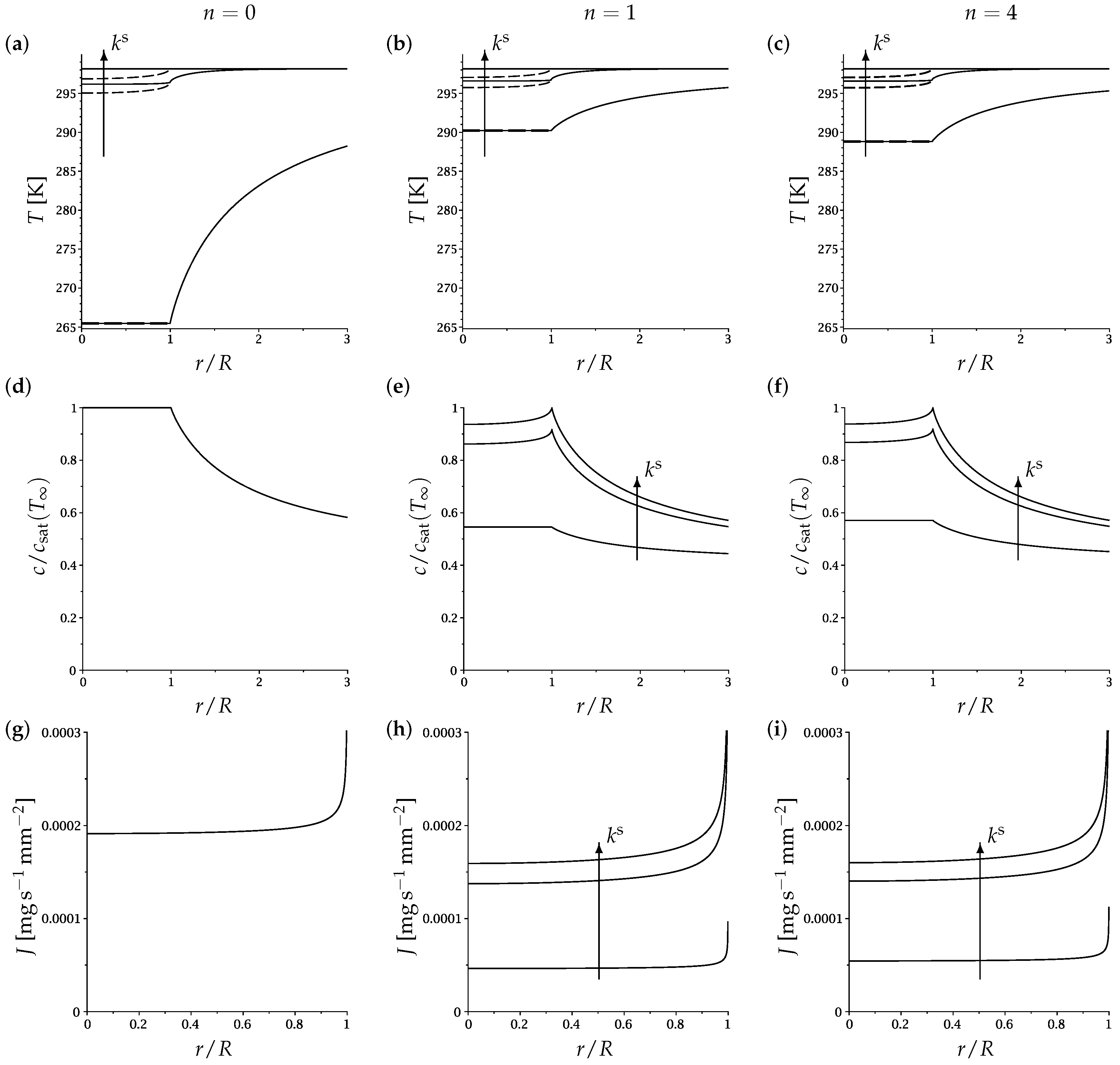
Figure 1 illustrates the role of the thermal conductivity of the substrate, k s . In Figure 1a, a perfectly conducting substrate anchors the temperature at the base of the droplet precisely at T = 298.15 K. Although the droplet cools slightly towards the top, the concentration of vapour close to the droplet remains high, and there is a high evaporation rate. On the other hand, in Figure 1b, finite substrate conductivity means that the substrate is cooled in the vicinity of the droplet. Thus, the droplet is cooler, the concentration of vapour close to the droplet is lower, and the evaporation rate is reduced, relative to Figure 1a. (Specifically, the volumetric evaporation rate is 0.00347 mm 3 s 1 for the droplet in Figure 1a and 0.00301 mm 3 s 1 for the droplet in Figure 1b).
Figure 2 explores these effects more quantitatively by examining the temperature [(a–c)], the vapour concentration [(d–f)], and the evaporative flux [(g–i)] along the free surface of the droplet and the upper surface of the substrate in various conditions. The first column [(a,d,g)] shows the results for the decoupled model, in which c sat is independent of temperature; it illustrates how increasing k s anchors the temperature of the droplet and the adjoining substrate more tightly to T . In the other two columns, c sat depends on temperature. This dependence reduces the overall degree of cooling through the negative feedback between cooling and evaporation, with the effect being more marked for lower values of k s [compare (b) and (c) with (a)]. We also see the reduction in concentration both at and adjacent to the free surface of the droplet [(e,f)] and the consequent reduction in flux [(h,i)]; again, all of these effects are most pronounced for lower values of k s . Note that the third column [(c,f,i)] corresponds to Figure 1.
The difference between the second column [(b,e,h)] and the third column [(c,f,i)] of Figure 2 is the number of terms taken in the polynomial approximation to c sat , given by Equation (6). Using the linear approximation [ n = 1 ; (b,e,h)] leads to a stronger variation of c sat with T, and thus to a greater difference from the decoupled model [ n = 0 ; (a,d,g)], than using the more accurate quartic approximation [ n = 4 ; (c,f,i)]. However, the effect of using the more accurate approximation is small in this case.
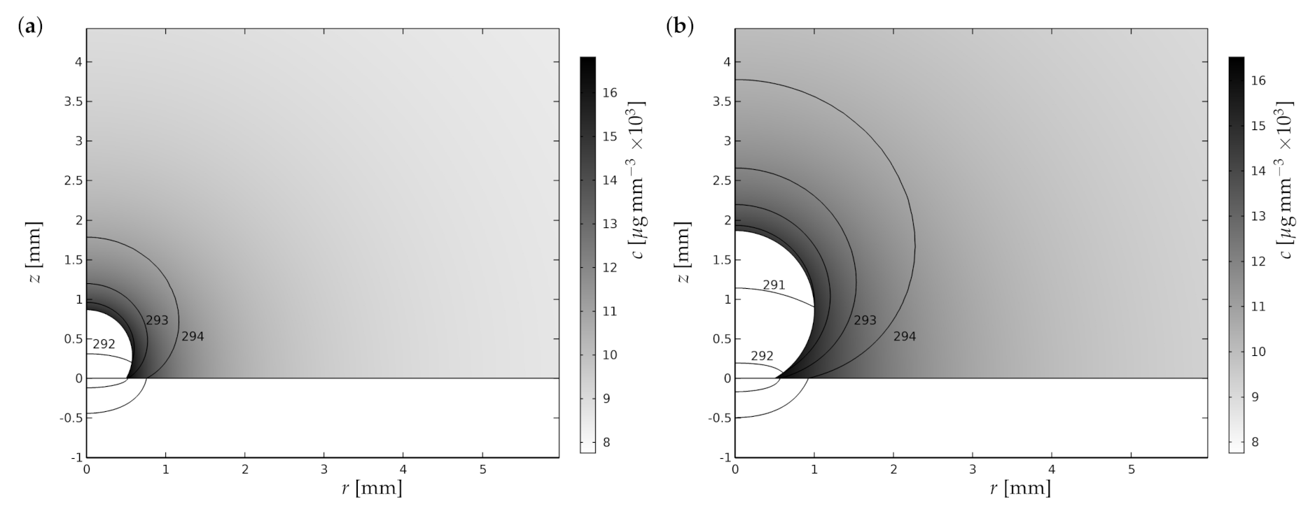
Figure 3 illustrates the role of the contact area between the droplet and the substrate and the contact angle. For a given contact radius, a larger contact angle means that the thermal anchoring is less effective and the droplet is able to cool more, and thus to evaporate less. (A similar effect is seen if the droplet volume is kept the same while the contact angle is increased and the contact radius is decreased.).
Since the thermal conductivity of the atmosphere is much lower than those of the substrate and the droplet, conduction through the atmosphere is insignificant unless the contact area is very small. However, even a perfectly non-wetting droplet with contact angle of θ = π and zero contact area is still in weak thermal communication with the substrate via the atmosphere. We will return to this point in Section 4, where we examine the effect of the initial contact angle on the lifetime of a droplet.
Figure 4 again explores these effects more quantitatively by examining the temperature [(a–c)], the vapour concentration [(d–f)], and the evaporative flux [(g–i)] along the free surface of the droplet and the upper surface of the substrate in various conditions; note that the curves are now multi-valued because the droplet overhangs part of the substrate. Similar trends are evident to those shown in Figure 2, with the exception that on a perfectly insulating substrate the divergence of the flux at the contact line is suppressed. Note that the third column [(c,f,i)] corresponds to Figure 3b.
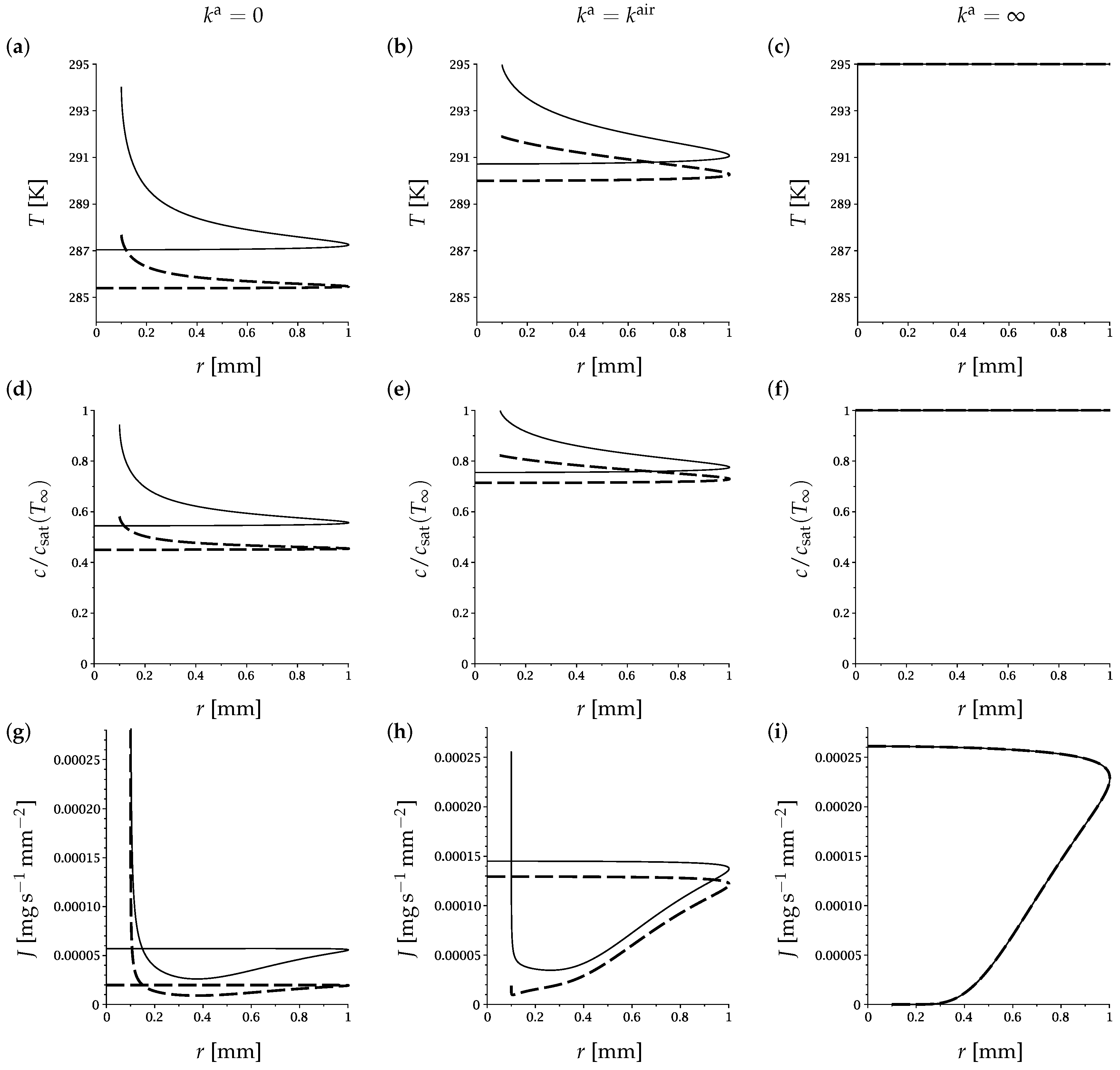
Finally, Figure 5 explores the effect of varying the thermal conductivity of the atmosphere, k a . A large contact angle θ = π 0.1 is taken in order to maximise the role of the atmosphere, and a linear variation of c sat with T is taken in order to maximise the negative feedback between cooling and evaporation. Comparing the first column [ k a = 0 ; (a,d,g)] with the second [ k a = k air ; (b,e,h)] makes it clear that heat conduction through the atmosphere plays a role in thermal anchoring for large contact angles. Comparing the first two columns with the third [ k a = ; (c,f,i)], which corresponds to an isothermal atmosphere, also demonstrates the importance of modelling the temperature of the atmosphere correctly.

4. The Lifetime of a Droplet

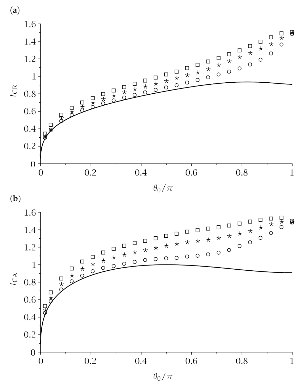
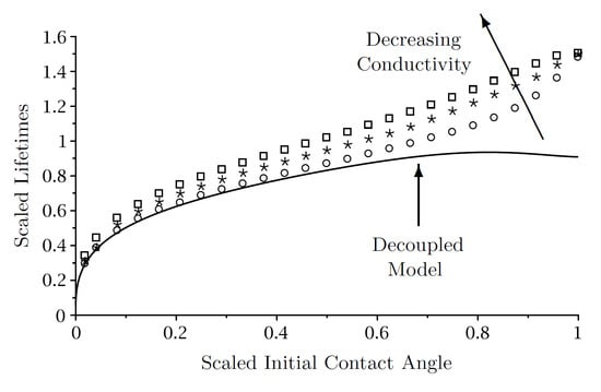
Figure 6 illustrates how the lifetimes of droplets evaporating in the CR mode [Figure 6a] and the CA mode [Figure 6b] depend on the scaled initial contact angle θ 0 / π for a wide range of values of the thermal conductivity of the substrate, k s . The lifetimes plotted in Figure 6 have been nondimensionalised using the timescale introduced by Stauber et al. [9], namely
ρ 2 D ( c sat ( T ) c ) 3 V 0 2 π 2 / 3 ,
where
V 0 = π R 0 3 sin θ 0 ( 2 + cos θ 0 ) 3 ( 1 + cos θ 0 ) 2 ,
R 0 and θ 0 are the initial volume, contact radius and contact angle of the droplet, respectively. In the decoupled model (but not the fully coupled model), using the scaling (7) eliminates all of the other parameters from the problem.
Stauber et al. [9] showed that the lifetimes of droplets according to the decoupled model behave like t CR = O ( θ 0 1 / 3 ) 0 + and t CA 3 t CR / 2 0 + in the limit θ 0 0 + , increase to the maximum values t CR = 0.9354 at θ 0 = θ crit where θ crit 2.5830 radians 148 and t CA = 1 at θ 0 = π / 2 , and then decrease to the same value of t CR = t CA = t π = ( 4 1 / 3 log 2 ) 1 0.9088 at θ 0 = π , with t CR < t CA for 0 < θ 0 < θ crit but t CA < t CR for θ crit < θ 0 < π . These lifetimes are also shown (with solid curves) in Figure 6 for comparison with the present results obtained using the fully coupled model. In particular, Figure 6 confirms, as noted in Section 2.1, that the decoupled model provides a lower bound on the lifetime of a droplet.
Figure 6 shows that the lifetimes of droplets of water can be strongly influenced by thermal effects. In particular, while the influence of thermal effects is rather weak for droplets with small initial contact angles, it is much stronger for droplets with large initial contact angles and, as Figure 6 shows, can extend the lifetime of a droplet by more than 50 % compared to the corresponding prediction of the decoupled model in which thermal effects have no influence on the lifetime. Figure 6 also shows that the lifetime of a droplet increases as k s decreases (i.e., a droplet on a poor conductor has a longer lifetime than the same droplet on a good conductor), and that t CR < t CA for all initial contact angles (i.e., the lifetime of a droplet evaporating in the CR mode is always shorter than that of the same droplet evaporating in the CA mode). This latter behaviour is qualitatively different from that according to the decoupled model, which, as we have already noted, predicts that t CA < t CR for θ crit < θ 0 < π . In addition, Figure 6 shows that while both t CR and t CA generally increase as θ 0 increases, for droplets on less conductive substrates evaporating in the CA mode, t CA decreases slightly as θ 0 approaches π .
The broad trends evident in Figure 6 can be understood in terms of the thermal anchoring described in Section 3. The generally longer lifetimes of droplets with larger initial contact angles or on less conductive substrates is because an increase in the initial contact angle or a reduction in the thermal conductivity of the substrate both weaken the thermal anchoring, and hence make the negative feedback between cooling and evaporation more effective. Similarly, the tendency for a droplet to evaporate faster in the CR mode than in the CA mode when thermal effects are significant is because in the CA mode (but not, of course, in the CR mode) the contact area between the droplet and the substrate shrinks over time, also weakening the thermal anchoring.
As Stauber et al. [11] described, in the limit of a perfectly non-wetting (i.e., spherical) droplet with contact angle θ θ 0 = π and zero contact radius R R 0 = 0 the extreme modes coincide, and so, in particular, their lifetimes are the same (i.e., t CR = t CA = t π when θ 0 = π ). As we have already noted, according to the decoupled model t π 0.9088 . However, as Figure 6 shows, according to the fully coupled model the lifetime of a perfectly non-wetting droplet is significantly longer than this and, due to the weak thermal communication between the droplet and the substrate via the atmosphere mentioned in Section 3, is weakly dependent on k s .
We note that the lifetimes reported in Figure 6 are for droplets with initial contact radius R 0 = 1 mm on a substrate of thickness h s = 1 mm. Different values of R 0 and h s would, of course, lead to different values of t CR and t CA , as would a series of calculations in which the initial volume of the droplet V 0 was held constant, however the underlying physical mechanisms would be unchanged, and so we would expect the broad trends to be similar.

5. Conclusions

In the present work we gave a detailed account of the effect of the thermal properties of the system (and, in particular, the thermal conductivity of the substrate) on the lifetime of an evaporating sessile droplet of water. We used the fully coupled model which involves determining the temperature of the droplet, the substrate and the atmosphere, and calculated the evolutions, and hence the lifetimes, of droplets of water evaporating in both of the extreme modes. This work unifies, extends, and in some aspects corrects, previous studies that have considered various aspects of the problem separately.
The principal findings of this study are encapsulated in Figure 6, which shows how the lifetimes of droplets of water can be strongly influenced by thermal effects. In particular, Figure 6 shows that droplets with larger initial contact angles or on less conductive substrates generally have longer lifetimes than those with smaller initial contact angles or on more conductive substrates. The physical mechanism by which the thermal properties of the system influence the evaporation can be understood in terms of the thermal anchoring between the droplet and the lower surface of the substrate. Specifically, heat transfer from the substrate to the droplet tends to anchor the temperature of the droplet to that of the lower surface of the substrate, reducing the evaporative cooling and weakening the negative feedback between cooling and evaporation. Thus, droplets in situations which the thermal anchoring is strong tend to evaporate faster and hence have shorter lifetimes than those in which it is weak.
There are, of course, many other aspects of droplet evaporation which remain the subject of ongoing research. For example, in certain circumstances, convective fluid, vapour and/or heat transfer driven by density and/or temperature differences (see, for example, [15,18,29,30,31,32,33,34]), none of which are included in the present work, can all have a significant effect on the evaporation of a droplet. Another particularly active and interesting area is the competitive evaporation of multiple droplets (see, for example, [16,35,36,37,38,39]), and we suggest that considering the mutual influence of droplets through thermal as well as vapour effects would be an interesting direction for further research.

Author Contributions

Conceptualization, K.S. and S.K.W.; software, F.G.H.S.; mathematical analysis, F.G.H.S., S.K.W. and D.P.; numerical analysis, F.G.H.S.; writing, D.P. and S.K.W.; visualization, F.G.H.S. and D.P.; supervision, S.K.W., D.P. and K.S.; funding acquisition, S.K.W. and K.S. All authors have read and agreed to the published version of the manuscript.

Funding

This research was funded via a Research Studentship for F.G.H.S. by the UK Engineering and Physical Sciences Research Council (EPSRC) through EPSRC Doctoral Training Partnership Grant EP/N509760/1, the University of Strathclyde, and the University of Edinburgh.

Institutional Review Board Statement

Not applicable.

Informed Consent Statement

Not applicable.

Data Availability Statement

All of the numerical results presented in the present work can be reproduced by solving the system of equations and boundary conditions described in Section 2.

Acknowledgments

The authors are grateful to Brian R. Duffy and Alexander W. Wray (both University of Strathclyde) for insightful discussions about various aspects of droplet evaporation.

Conflicts of Interest

The authors declare no conflict of interest.

References

  1. Larson, R.G. Transport and deposition patterns in drying sessile droplets. AIChE J. 2014, 60, 1538–1571. [Google Scholar] [CrossRef] [Green Version]
  2. Brutin, D.; Starov, V. Recent advances in droplet wetting and evaporation. Chem. Soc. Rev. 2018, 47, 558–585. [Google Scholar] [CrossRef] [PubMed]
  3. Giorgiutti-Dauphiné, F.; Pauchard, L. Drying drops. Eur. Phys. J. E 2018, 41, 32. [Google Scholar] [CrossRef] [PubMed]
  4. Picknett, R.G.; Bexon, R. The evaporation of sessile or pendant drops in still air. J. Colloid Interface Sci. 1977, 61, 336–350. [Google Scholar] [CrossRef]
  5. Askounis, A.; Orejon, D.; Koutsos, V.; Sefiane, K.; Shanahan, M.E.R. Nanoparticle deposits near the contact line of pinned volatile droplets: Size and shape revealed by atomic force microscopy. Soft Matter 2011, 7, 4152–4155. [Google Scholar] [CrossRef]
  6. Orejon, D.; Sefiane, K.; Shanahan, M.E.R. Stick–slip of evaporating droplets: Substrate hydrophobicity and nanoparticle concentration. Langmuir 2011, 27, 12834–12843. [Google Scholar] [CrossRef]
  7. Nguyen, T.A.H.; Nguyen, A.V. Increased evaporation kinetics of sessile droplets by using nanoparticles. Langmuir 2012, 28, 16725–16728. [Google Scholar] [CrossRef]
  8. Dash, S.; Garimella, S.V. Droplet evaporation dynamics on a superhydrophobic surface with negligible hysteresis. Langmuir 2013, 29, 10785–10795. [Google Scholar] [CrossRef]
  9. Stauber, J.M.; Wilson, S.K.; Duffy, B.R.; Sefiane, K. On the lifetimes of evaporating droplets. J. Fluid Mech. 2014, 744, R2. [Google Scholar] [CrossRef] [Green Version]
  10. Stauber, J.M.; Wilson, S.K.; Duffy, B.R.; Sefiane, K. On the lifetimes of evaporating droplets with related initial and receding contact angles. Phys. Fluids 2015, 27, 122101. [Google Scholar] [CrossRef] [Green Version]
  11. Stauber, J.M.; Wilson, S.K.; Duffy, B.R.; Sefiane, K. Evaporation of droplets on strongly hydrophobic substrates. Langmuir 2015, 31, 3653–3660. [Google Scholar] [CrossRef]
  12. Deitrich, E.; Kooij, E.S.; Zhang, X.; Zandvliet, H.J.W.; Lohse, D. Stick-jump mode in surface droplet dissolution. Langmuir 2015, 31, 4696–4703. [Google Scholar] [CrossRef] [PubMed] [Green Version]
  13. Zhang, X.; Wang, J.; Bao, L.; Dietrich, E.; van der Veen, R.C.A.; Peng, S.; Friend, J.; Zandvliet, H.J.W.; Yeo, L.; Lohse, D. Mixed mode of dissolving immersed nanodroplets at a solid–water interface. Soft Matter 2015, 11, 1889–1900. [Google Scholar] [CrossRef] [PubMed]
  14. Schofield, F.G.H.; Wilson, S.K.; Pritchard, D.; Sefiane, K. The lifetimes of evaporating sessile droplets are significantly extended by strong thermal effects. J. Fluid Mech. 2018, 851, 231–244. [Google Scholar] [CrossRef] [Green Version]
  15. Pan, Z.; Weibel, J.A.; Garimella, S.V. Transport mechanisms during water droplet evaporation on heated substrates of different wettability. Int. J. Heat Mass Transf. 2020, 152, 119524. [Google Scholar] [CrossRef]
  16. Wray, A.W.; Duffy, B.R.; Wilson, S.K. Competitive evaporation of multiple sessile droplets. J. Fluid Mech. 2020, 884, A45. [Google Scholar] [CrossRef] [Green Version]
  17. Dunn, G.J.; Wilson, S.K.; Duffy, B.R.; David, S.; Sefiane, K. A mathematical model of the evaporation of a thin sessile liquid droplet: Comparison between experiment and theory. Colloids Surf. A Physicochem. Eng. Asp. 2008, 323, 50–55. [Google Scholar] [CrossRef] [Green Version]
  18. Dunn, G.J.; Wilson, S.K.; Duffy, B.R.; David, S.; Sefiane, K. The strong influence of substrate conductivity on droplet evaporation. J. Fluid Mech. 2009, 623, 329–351. [Google Scholar] [CrossRef] [Green Version]
  19. Sefiane, K.; Wilson, S.K.; David, S.; Dunn, G.J.; Duffy, B.R. On the effect of the atmosphere on the evaporation of sessile droplets of water. Phys. Fluids 2009, 21, 062101. [Google Scholar] [CrossRef] [Green Version]
  20. Sefiane, K.; Bennacer, R. An expression for droplet evaporation incorporating thermal effects. J. Fluid Mech. 2011, 667, 260–271. [Google Scholar] [CrossRef]
  21. Sobac, B.; Brutin, D. Thermal effects of the substrate on water droplet evaporation. Phys. Rev. E 2012, 86, 021602. [Google Scholar] [CrossRef] [PubMed] [Green Version]
  22. Ait Saada, M.; Chikh, S.; Tadrist, L. Evaporation of a sessile drop with pinned or receding contact line on a substrate with different thermophysical properties. Int. J. Heat Mass Transf. 2013, 58, 197–208. [Google Scholar] [CrossRef]
  23. Lopes, M.C.; Bonaccurso, E.; Gambaryan-Roisman, T.; Stephan, P. Influence of the substrate thermal properties on sessile droplet evaporation: Effect of transient heat transport. Colloids Surf. A Physicochem. Eng. Asp. 2013, 432, 64–70. [Google Scholar] [CrossRef]
  24. Diddens, C.; Tan, H.; Lv, P.; Versluis, M.; Kuerten, J.G.M.; Zhang, X.; Lohse, D. Evaporating pure, binary and ternary droplets: Thermal effects and axial symmetry breaking. J. Fluid Mech. 2017, 823, 470–497. [Google Scholar] [CrossRef] [Green Version]
  25. Schofield, F.G.H. Mathematical Modelling of Droplet Evaporation. Ph.D. Thesis, University of Strathclyde, Glasgow, UK, 2020. [Google Scholar]
  26. Deegan, R.D.; Bakajin, O.; Dupont, T.F.; Huber, G.; Nagel, S.R.; Witten, T.A. Capillary flow as the cause of ring stains from dried liquid drops. Nature 1997, 389, 827–829. [Google Scholar] [CrossRef]
  27. Popov, Y.O. Evaporative deposition patterns: Spatial dimensions of the deposit. Phys. Rev. E 2005, 71, 036313. [Google Scholar] [CrossRef] [Green Version]
  28. COMSOLMultiphysics v. 5.4. COMSOL AB, Stockholm, Sweden. Available online: www.comsol.com (accessed on 3 December 2018).
  29. Hu, H.; Larson, R.G. Analysis of the effects of Marangoni stresses on the microflow in an evaporating sessile droplet. Langmuir 2005, 21, 3972–3980. [Google Scholar] [CrossRef]
  30. Shahidzadeh-Bonn, N.; Rafaï, S.; Azouni, A.; Bonn, D. Evaporating droplets. J. Fluid Mech. 2006, 549, 307–313. [Google Scholar] [CrossRef]
  31. Ristenpart, W.D.; Kim, P.G.; Domingues, C.; Wan, J.; Stone, H.A. Influence of substrate conductivity on circulation reversal in evaporating drops. Phys. Rev. Lett. 2007, 99, 234502. [Google Scholar] [CrossRef] [Green Version]
  32. Dunn, G.J.; Duffy, B.R.; Wilson, S.K.; Holland, D. Quasi-steady spreading of a thin ridge of fluid with temperature-dependent surface tension on a heated or cooled substrate. Quart. J. Mech. Appl. Math. 2009, 62, 365–402. [Google Scholar] [CrossRef] [Green Version]
  33. Dietrich, E.; Wildeman, S.; Visser, C.W.; Hofhuis, K.; Kooij, E.S.; Zandvliet, H.J.W.; Lohse, D. Role of natural convection in the dissolution of sessile droplets. J. Fluid Mech. 2016, 794, 45–67. [Google Scholar] [CrossRef] [Green Version]
  34. Diddens, C.; Li, Y.; Lohse, D. Competing Marangoni and Rayleigh convection in evaporating binary droplets. J. Fluid Mech. 2021, 914, A23. [Google Scholar] [CrossRef]
  35. Schäfle, C.; Bechinger, C.; Rinn, B.; David, C.; Leiderer, P. Cooperative evaporation in ordered arrays of volatile droplets. Phys. Rev. Lett. 1999, 83, 5302–5305. [Google Scholar] [CrossRef] [Green Version]
  36. Sokuler, M.; Auernhammer, G.K.; Liu, C.J.; Bonaccurso, E.; Butt, H.J. Dynamics of condensation and evaporation: Effect of inter-drop spacing. Europhys. Lett. 2010, 89, 36004. [Google Scholar] [CrossRef]
  37. Carrier, O.; Shahidzadeh-Bonn, N.; Zargar, R.; Aytouna, M.; Habibi, M.; Eggers, J.; Bonn, D. Evaporation of water: Evaporation rate and collective effects. J. Fluid Mech. 2016, 798, 774–786. [Google Scholar] [CrossRef] [Green Version]
  38. Schofield, F.G.H.; Wray, A.W.; Pritchard, D.; Wilson, S.K. The shielding effect extends the lifetimes of two-dimensional sessile droplets. J. Eng. Math. 2020, 120, 89–110. [Google Scholar] [CrossRef] [Green Version]
  39. Wray, A.W.; Wray, P.S.; Duffy, B.R.; Wilson, S.K. Contact-line deposits from multiple evaporating droplets. arXiv 2021, arXiv:2103.07221. [Google Scholar]
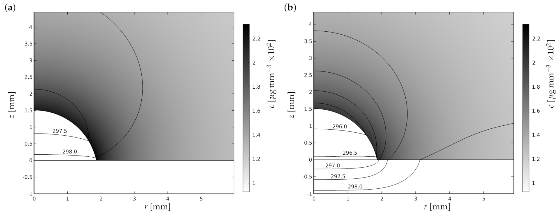
Figure 1. Vapour concentration for a droplet of water with contact angle θ = 1.361 radians and contact radius R = 1.86 mm evaporating into air with T = 298.15 K on (a) a perfectly conducting substrate ( k s = ) and (b) a PTFE substrate ( k s = 0.25 W m 1 K 1 ). Shown also are temperature contours of T, T s and T a in K.
Fluids 06 00141 g001
Figure 2. Numerically calculated solutions for (ac) the temperature, (df) the vapour concentration, and (gi) the evaporative flux for a droplet of water with contact angle θ = 1.361 radians and contact radius R = 1.86 mm evaporating into air with T = 298.15 K on a perfectly conducting substrate ( k s = ), a PTFE substrate ( k s = 0.25 W m 1 K 1 ), and a perfectly insulating substrate ( k s = 0 ). In (ac) the dashed curves show the temperature along the free surface of the droplet for r < R and the solid curves show the temperature along the upper surface of the substrate, while (df) show the concentration along the free surface of the droplet for r < R and along the upper surface of the substrate for r > R . Column [(a,d,g)] was obtained using n = 0 in Equation (6), column [(b,e,h)] was obtained using n = 1 , and column [(c,f,i)] was obtained using n = 4 . The arrows indicate the direction of increasing k s .
Fluids 06 00141 g002
Figure 3. Vapour concentration for a droplet of water with contact angle (a) θ = 2 π / 3 and (b) θ = 5 π / 6 and contact radius R = 0.5 mm evaporating into air with T = 295 K on a PTFE substrate ( k s = 0.25 W m 1 K 1 ). Shown also are temperature contours of T, T s and T a in K.
Fluids 06 00141 g003
Figure 4. Numerically calculated solutions for (ac) the temperature, (df) the vapour concentration, and (gi) the evaporative flux for a droplet of water with contact angle θ = 5 π / 6 and contact radius R = 0.5 mm evaporating into air with T = 295 K on a perfectly conducting substrate ( k s = ), a PTFE substrate ( k s = 0.25 W m 1 K 1 ), and a perfectly insulating substrate ( k s = 0 ). In (ac) the dashed curves show the temperature along the free surface of the droplet for r < R and the solid curves show the temperature along the upper surface of the substrate, while (df) show the concentration along the free surface of the droplet for r < R and along the upper surface of the substrate for r > R . Column [(a,d,g)] was obtained using n = 0 in Equation (6), column [(b,e,h)] was obtained using n = 1 , and column [(c,f,i)] was obtained using n = 4 . The arrows indicate the direction of increasing k s .
Fluids 06 00141 g004
Figure 5. Numerically calculated solutions for (ac) the temperature along the free surface of the droplet, (df) the vapour concentration along the free surface of the droplet, and (gi) the evaporative flux for a droplet of water with contact angle θ = π 0.1 and contact radius R = 0.1 mm evaporating into atmospheres with T = 295 K and thermal conductivities k a = 0 [column (a,d,g)], k a = k air = 2.597 × 10 2 W m 1 K 1 [column (b,e,h)] and k a = [column (c,f,i)] on an aluminium substrate ( k s = 2.73 × 10 2 W m 1 K 1 , solid curves) and a PTFE substrate ( k s = 0.25 W m 1 K 1 , dashed curves). All of the results are obtained using n = 1 in Equation (6).
Fluids 06 00141 g005
Figure 6. Numerically calculated dimensionless lifetimes of droplets of water with initial contact radius R = 1 mm in (a) the CR mode, t CR , and (b) the CA mode, t CA , evaporating into air with T = 295 K on aluminium ( k s = 237 W m 1 K 1 , circles ∘), HDPE ( k s = 0.50 W m 1 K 1 , stars ☆) and PTFE ( k s = 0.25 W m 1 K 1 , squares □) substrates of thickness h s = 1 mm plotted as functions of the scaled initial contact angle θ 0 / π . The lifetimes have been nondimensionalised using the timescale (7), and the corresponding lifetimes according to the decoupled model obtained by Stauber et al. [9] are shown with solid lines.
Fluids 06 00141 g006
Publisher’s Note: MDPI stays neutral with regard to jurisdictional claims in published maps and institutional affiliations.