
An Optimized Method for 3D Magnetic Navigation of Nanoparticles inside Human Arteries


 ,
,  and
and 
Abstract
1. Introduction
2. Materials and Methods
2.1. Governing Equations
2.2. Model Validation
2.3. Determination of the Appropriate Magnetic Gradients
2.4. Driving Process
2.5. Simulation Details
3. Results
4. Discussion
5. Conclusions
Author Contributions
Funding
Institutional Review Board Statement
Informed Consent Statement
Data Availability Statement
Acknowledgments
Conflicts of Interest
References
- Senyei, A.; Widder, K.; Czerlinski, C. Magnetic guidance of drug carrying micro- spheres. Appl. Phys. 1978, 49, 3578–3583. [Google Scholar] [CrossRef]
- Widder, K.; Senyei, A.; Scarpelli, G. Magnetic microspheres: A model system of site specific drug delivery in vivo. Proc. Soc. Exp. Biol. Med. 1978, 158, 141–146. [Google Scholar] [CrossRef] [PubMed]
- Patra, J.K.; Das, G.; Fraceto, L.F.; Campos, E.V.R.; Rodriguez-Torres, M.; Acosta-Torres, L.S.; Diaz-Torres, L.A.; Swamy, M.K.; Sharma, S.; Habtemariam, S.; et al. Nano based drug delivery systems: Recent developments and future prospects. J. Nanobiotechnol. 2018, 16, 71. [Google Scholar] [CrossRef]
- Arias, L.S.; Pessan, J.P.; Vieira, A.P.M.; Toito de Lima, T.M.; Delbem, A.C.B.; Monteiro, D.R. Iron Oxide Nanoparticles for Biomedical Applications: A Perspective on Synthesis, Drugs, Antimicrobial Activity, and Toxicity. Antibiotics 2018, 7, 46. [Google Scholar] [CrossRef] [PubMed]
- Ali, A.; Zafar, H.; Zia, M.; Haq, I.U.; Phull, A.R.; Ali, J.S.; Hussain, A. Synthesis, characterization, applications, and challenges of iron oxide nanoparticles. Nanotechnol. Sci. Appl. 2016, 9, 49–67. [Google Scholar] [CrossRef]
- Giustini, A.J.; Petryk, A.A.; Cassim, S.M.; Tate, J.A.; Baker, I.; Hoopes, P.J. Magnetic nanoparticle hyperthermia in cancer treatment. Nano LIFE 2010, 1, 17–32. [Google Scholar] [CrossRef]
- Daughton, C.G.; Ruhoy, I.S. Lower-dose prescribing: Minimizing “side effects” of pharmaceuticals on society and the environment. Sci. Total Environ. 2013, 443, 324–337. [Google Scholar] [CrossRef] [PubMed]
- Mao, X.; Xu, J.; Cui, H. Functional Nanoparticles for Magnetic Resonance Imaging. Wires Nanomed. Nanobiotechnol. 2016, 8, 814–841. [Google Scholar] [CrossRef] [PubMed]
- Gleich, B.; Hellwig, N.; Bridell, H.; Jurgons, R.; Seliger, C.; Alexiou, C.; Wolf, B.; Weyh, T. Design and evaluation of magnetic fields for nanoparticle drug targeting in cancer. IEEE Trans. Nanotechnol. 2007, 6, 164–169. [Google Scholar] [CrossRef]
- Kubo, T.; Sugita, T.; Shimose, S.; Nitta, Y.; Ikuta, Y.; Murakami, Y.T. Targeted delivery of anticancer drugs with intravenously administered magnetic liposomes in osteosarcoma-bearing hamsters. Int. J. Oncol. 2000, 17, 309–315. [Google Scholar] [CrossRef] [PubMed]
- Yellen, B.B.; Forbes, Z.G.; Halverson, D.S.; Fridman, G.; Barbee, K.A.; Chorny, M.; Levy, R.; Friedman, G. Targeted drug delivery to magnetic implants for therapeutic applications. J. Magn. Magn. Mater. 2005, 293, 647–654. [Google Scholar] [CrossRef]
- Karvelas, E.G.; Lampropoulos, N.K.; Karakasidis, T.E.; Sarris, I.E. A computational tool for the estimation of the optimum gradient magnetic field for the magnetic driving of the spherical particles in the process of cleaning water. Desalin. Water Treat. 2017, 99, 27–33. [Google Scholar] [CrossRef]
- Mathieu, J.B.; Martel, S. Aggregation of magnetic microparticles in the context of targeted therapies actuated by a magnetic resonance imaging system. J. Appl. Phys. 2009, 106, 044904. [Google Scholar] [CrossRef]
- Vartholomeos, P.; Mavroidis, C. In silico studies of magnetic microparticle aggregations in fluid environments for MRI-guided drug delivery. IEEE Trans. Biomed. Eng. 2012, 59, 3028–3038. [Google Scholar] [CrossRef]
- Karvelas, E.G.; Lampropoulos, N.K.; Sarris, I.E. A numerical model for aggregations formation and magnetic driving of spherical particles based on OpenFOAM. Comput. Methods Programs Biomed. 2017, 142, 21–30. [Google Scholar] [CrossRef] [PubMed]
- Karvelas, E.G.; Karakasidis, T.E.; Sarris, I.E. Computational analysis of paramagnetic spherical Fe3O4 nanoparticles under permanent magnetic fields. Comput. Mater. Sci. 2018, 154, 464–471. [Google Scholar] [CrossRef]
- Karvelas, E.G.; Lampropoulos, N.K.; Benos, L.T.; Karakasidis, T.E.; Sarris, I.E. On the magnetic aggregation of Fe3O4 nanoparticles. Comput. Methods Programs Biomed. 2021, 178, 105778. [Google Scholar] [CrossRef]
- Fogelson, A.L.; Neeves, K.B. Fluid Mechanics of Blood Clot Formation. Annu. Rev. Fluid Mech. 2015, 47, 377–403. [Google Scholar] [CrossRef]
- Jackson, J.D. Classical Electrodynamics, 3rd ed.; Wiley: Hoboken, NJ, USA, 1998. [Google Scholar]
- Agiotis, L.; Theodorakakos, I.; Samothrakitis, S.; Papazoglou, S.; Zergioti, I.; Raptis, Y.S. Magnetic manipulation of superparamagnetic nanoparticles in a microfluidic system for drug delivery applications. J. Magn. Magn. Mater. 2016, 401, 956–964. [Google Scholar] [CrossRef]
- Hedayatnasab, Z.; Abnisa, F.; Daud, W.M.A.Q. Review on magnetic nanoparticles for magnetic nanofluid hyperthermia application. Mater. Des. 2017, 123, 174–196. [Google Scholar] [CrossRef]
- Cervadoro, A.; Giverso, C.; Pande, R.; Sarangi, S.; Preziosi, L.; Wosik, J.; Brazdeikis, A. Design Maps for the Hyperthermic Treatment of Tumors with Superparamagnetic Nanoparticles. PLoS ONE 2013, 8, e57332. [Google Scholar] [CrossRef]
- Myrovali, E.; Maniotis, N.; Samaras, T.; Angelakeris, M. Spatial focusing of magnetic particle hyperthermia. Nanoscale Adv. 2020, 2, 408–416. [Google Scholar] [CrossRef]
- Simeonidis, K. In-situ particles reorientation during magnetic hyperthermia application: Shape matters twice. Sci. Rep. 2016, 6, 38382. [Google Scholar] [CrossRef]
- Numata, S.; Itatani, K.; Kawajiri, H.; Yamazaki, S.; Kanda, K.; Yaku, H. Computational fluid dynamics simulation of the right subclavian artery cannulation. J. Thorac. Cardiovasc. Surg. 2017, 154, 480–487. [Google Scholar] [CrossRef] [PubMed]
- Arjunan, A.; Demetriou, M.; Baroutaji, A.; Wang, C. Mechanical performance of highly permeable laser melted Ti6Al4V bone scaffolds. Behav. Biomed. Mater. 2020, 102, 103517. [Google Scholar] [CrossRef]
- Erisken, C.; Tsiantis, A.; Papathanasiou, T.D.; Karvelas, E.G. Collagen fibril diameter distribution affects permeability of ligament tissue: A computational study on healthy and injured tissues. Comput. Methods Programs Biomed. 2020, 196, 105554. [Google Scholar] [CrossRef]
- Zhang, X.; Le, T.A.; Hoshiar, A.K.; Yoon, J. A Soft Magnetic Core can Enhance Navigation Performance of Magnetic Nanoparticles in Targeted Drug Delivery. IEEE/ASME Trans. Mechatron. 2018, 23, 1573–1584. [Google Scholar] [CrossRef]
- Pouponnea, P.; Leroux, J.-C.; Soulez, G.; Gaboury, L.; Martel, S. Co-encapsulation of magnetic nanoparticles and doxorubicin into biodegradable microcarriers for deep tissue targeting by vascular MRI navigation. Biomaterials 2011, 32, 3481–3486. [Google Scholar] [CrossRef] [PubMed]
- Zhang, X.; Le, T.A.; Yoon, J. Development of a real time imaging-based guidance system of magnetic nanoparticles for targeted drug delivery. J. Magn. Magn. Mater. 2017, 427, 345–351. [Google Scholar] [CrossRef]
- Martel, S.; Felfoul, O.; Mathieu, J.-B.; Chanu, A.; Tamaz, S.; Mohammadi, M.; Mankiewicz, M.; Tabatabei, N. MRI-based Medical Nanorobotic Platform for the Control of Magnetic Nanoparticles and Flagellated Bacteria for Target Interventions in Human Capillaries. Int. J. Robot. Res. 2009, 28, 1169–1182. [Google Scholar] [CrossRef]
- Kafash, A.; Le, T.A.; Yoon, J. Swarm of magnetic nanoparticles steering in multi-bifurcation vessels under fluid flow. J. Micro-Bio Robot. 2020, 16, 137–145. [Google Scholar]
- Tao, R.; Huang, K. Reducing blood viscosity with magnetic fields. Phys. Rev. E 2011, 84, 011905. [Google Scholar] [CrossRef] [PubMed]
- Waite, L. Biofluid Mechanics in Cardiovascular Systems; McGraw-Hill’s: New York, NY, USA, 2005. [Google Scholar]
- Hansen, N. The CMA evolution strategy: A comparing review. Adv. Estim. Distrib. Algorithms 2006, 192, 1769–1776. [Google Scholar]
- Weller, H.G.; Tabor, G.; Jasak, H.; Fureby, C. A tensorial approach to computational continuum mechanics using object-oriented techniques. Comput. Phys. 2010, 12, 620–631. [Google Scholar] [CrossRef]
- Kennedy, P.; Zheng, R. Flow Analysis of Injection Molds; Hanser: New York, NY, USA, 2013. [Google Scholar]
- Bharadvaj, B.K.; Mabon, R.F.; Giddens, D.P. Steady flow in a model of a human carotid bifurcation. Part 1-Flow visualization. J. Biomech. 1982, 15, 349–362. [Google Scholar] [CrossRef]
- Geuzaine, C.; Remacle, J.-F. Gmsh: A 3-D finite element mesh generator with built-in pre- and post-processing facilities. Int. J. Numer. Methods Eng. 2009, 79, 1309–1331. [Google Scholar] [CrossRef]
- Gijsen, F.J.H.; Vosse, F.N.V.; Janssen, J.D. The influence of the non-Newtonian properties of blood on the flow in the large arteries: Steady flow in a carotid bifurcation model. J. Biomech. 1999, 32, 601–608. [Google Scholar] [CrossRef]
- Nowogrodzki, A. The world’s strongest MRI machines are pushing human imaging to new limits. Nature 2018, 563, 24–26. [Google Scholar] [CrossRef]
- Segadal, L.; Matre, K. Blood velocity distribution in the human ascending aorta. Circulation 1987, 76, 90–100. [Google Scholar] [CrossRef]
- Pomella, N.; Wilhelm, E.N.; Kolyva, C.; Gonzalez-Alonso, J.; Rakobowchuk, M.; Khir, A.W. Common carotid artery diameter, blood flow velocity and wave intensity responses at rest and during exercise in young healthy humans: A reproducibility study. Ultrasound Med. Biol. 2017, 43, 943–957. [Google Scholar] [CrossRef]
- Koutsiaris, A.G.; Tachmitzi, S.V.; Papavasileiou, P.; Batis, N.; Koutoula, M.G.; Giannoukas, A.D.; Tsironi, E. Blood velocity pulse quantification in the human conjunctival pre-capillary arterioles. Microvasc. Res. 2010, 80, 202–208. [Google Scholar] [CrossRef] [PubMed]
- Griese, F. Simultaneous Magnetic Particle Imaging and Navigation of large superparamagnetic nanoparticles in bifurcation flow experiments. J. Magn. Magn. Mater. 2020, 498, 166206. [Google Scholar] [CrossRef]
- Manshadi, M.K.D. Delivery of magnetic micro/nanoparticles and magnetic-based drug/cargo into arterial flow for targeted therapy. Drug Deliv. 2018, 25, 1963–1973. [Google Scholar] [CrossRef]
- Grosse-Wortmann, L.; Grabitz, R.; Seghaye, M.C. Magnetic Guide-Wire Navigation in Pulmonary and Systemic Arterial Catheterization: Initial Experience in Pigs. J. Vasc. Interv. Radiol. 2007, 18, 545–551. [Google Scholar] [CrossRef] [PubMed]


| Bird-Carreau Parameters | ||
|---|---|---|
| Symbol | Value | Unit |
| Pa·s | ||
| Pa·s | ||
| 0.11 | s | |
| 0.392 | - | |
| Boundary Conditions | ||
|---|---|---|
| Boundary | Velocity | Pressure |
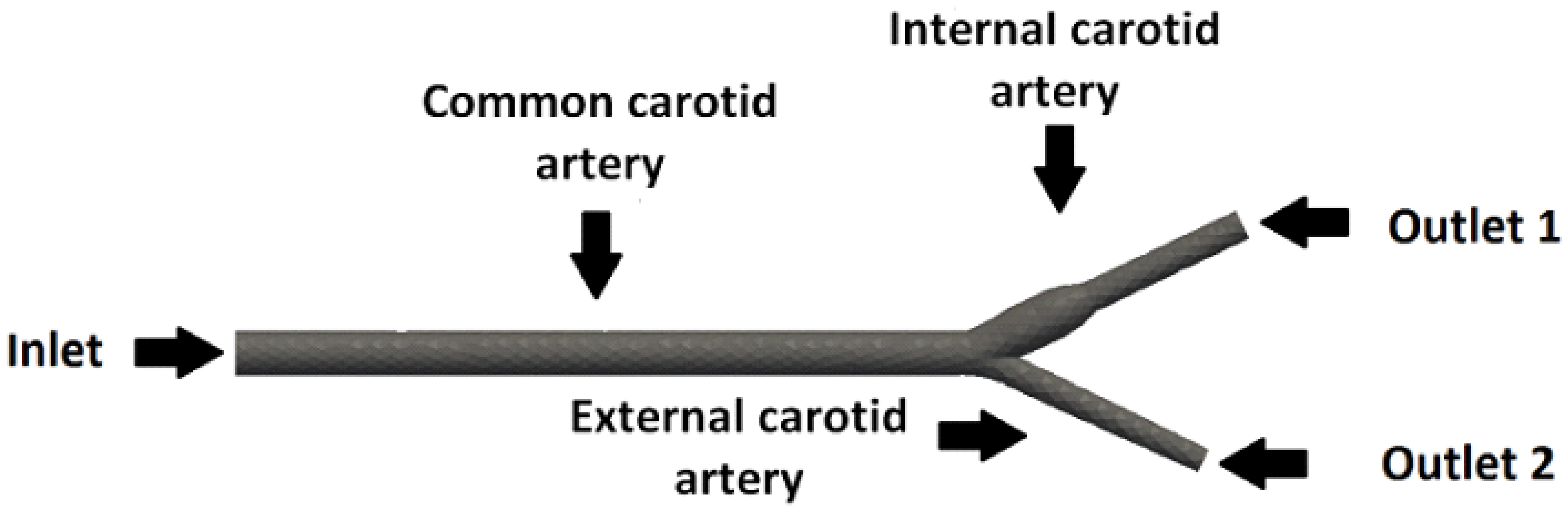
| Inlet | 0.08 m/s | Zero gradient |
| Outlet 1 | Zero gradient | 0 |
| Outlet 2 | Zero gradient | 0 |
| Walls | 0 | Zero gradient |
| Property | Units |
|---|---|
| Particles’ density | 5000 Kg/m |
| Young’s modulus | Pa |
| Poisson’s ratio | |
| Relative magnetic permeability | |
| Medium permeability | |
| Temperature | 288 K |
| Molecular mean free path |
Publisher’s Note: MDPI stays neutral with regard to jurisdictional claims in published maps and institutional affiliations. |
© 2021 by the authors. Licensee MDPI, Basel, Switzerland. This article is an open access article distributed under the terms and conditions of the Creative Commons Attribution (CC BY) license (http://creativecommons.org/licenses/by/4.0/).
Share and Cite
Karvelas, E.; Liosis, C.; Theodorakakos, A.; Sarris, I.; Karakasidis, T. An Optimized Method for 3D Magnetic Navigation of Nanoparticles inside Human Arteries. Fluids 2021, 6, 97. https://doi.org/10.3390/fluids6030097
Karvelas E, Liosis C, Theodorakakos A, Sarris I, Karakasidis T. An Optimized Method for 3D Magnetic Navigation of Nanoparticles inside Human Arteries. Fluids. 2021; 6(3):97. https://doi.org/10.3390/fluids6030097
Chicago/Turabian StyleKarvelas, Evangelos, Christos Liosis, Andreas Theodorakakos, Ioannis Sarris, and Theodoros Karakasidis. 2021. "An Optimized Method for 3D Magnetic Navigation of Nanoparticles inside Human Arteries" Fluids 6, no. 3: 97. https://doi.org/10.3390/fluids6030097
APA StyleKarvelas, E., Liosis, C., Theodorakakos, A., Sarris, I., & Karakasidis, T. (2021). An Optimized Method for 3D Magnetic Navigation of Nanoparticles inside Human Arteries. Fluids, 6(3), 97. https://doi.org/10.3390/fluids6030097