1. Introduction
It has long been known that when vehicles travel in close-proximity they experience changes in their aerodynamic characteristics compared to those of the condition of travelling alone. Amongst the most ‘visual’ applications have been the “slipstreaming” effect in motor racing, as typified by the 1971 Italian Grand Prix at Monza [
1], and the energy-saving benefits illustrated by professional cyclists travelling in pelotons or in echelon formations when riding in crosswinds [
2,
3]. However, for road-going vehicles, research into the organized or deliberate positioning of vehicles in close-proximity to gain an aerodynamic advantage seems to have been the subject of comparatively limited publications, with the most numerous being for heavy goods vehicles.
Although not specifically as an automotive application, Hoerner [
4], illustrated and numerically compared the aerodynamic drag of two equally-sized cylinders and of two thin symmetrical low-drag aerofoil sections in tandem. In effect, the comparison was between bluff and streamlined bodies. The tests on the cylinders resulted in significant drag reductions for both leading and trailing bodies up to an equivalent spacing of three cylinder diameters. Beyond a spacing of four diameters the drag of the leading body had returned to that of a single cylinder alone. For the trailing cylinder there was evidence of the reduction in drag continuing until a spacing of eight diameters. The aerofoil sections showed a different result. For the leading aerofoil a significant drag reduction was shown only up to a spacing of one chord length, after which and by three chord lengths, the drag had increased to that of a single aerofoil. The trailing aerofoil showed a drag reduction at zero spacing but as the spacing was increased by single chord length the drag increased to approximately four times that of a single aerofoil. Beyond this position the drag reduced such that at 5 chord lengths it was equal to that of a single aerofoil. By way of explantion, Hoerner suggested:
“We have to assume that the flow separates from the rear of the second strut because of the momentum deficiency within the wake coming from the first strut. The fact that the drag of the first section is decreased is explained by increased static pressure between the two struts pushing the first one forward, so to speak.”In motor racing the advantage sought in drag reduction by cars deliberately positioning in close longitudinal proximity is frequently referred to as “slip-streaming” or “drafting”. Romberg et al. [
5] showed the aerodynamic effects on the drag and lift of two, early 1970s, US stock-car racers when drafting in scale model wind tunnel tests. The results, for these classical 3-box style vehicles, were similar to those shown by Hoerner for the two cylinders in tandem. The benefit for the lead model existed up to a spacing of 1.5 car-lengths, while for the trailing model the most benefit was at a distance of 1 car-length with a drag reduction continuing to a spacing of 4 car-lengths.
Early work by Zabat, Browand et al. [
6,
7,
8] had shown the energy-saving potential of passenger cars travelling in close proximity, or as frequently termed “platooning”, through wind tunnel tests, using small-scale models, and in the results of fuel consumption measurements in field trials. The origins of the work were as a contribution to research into increasing road capacity by reducing vehicle spacing and therefore increasing traffic density of freeways in California.
Hucho [
9] also showed after Ewald [
10] the potential for platoons of between 2 and 10 homogeneous vehicles, to achieve useful drag-reduction benefits even for vehicle-to-vehicle spacings of greater than 50% of vehicle length. Perhaps just as significantly, using Ewald’s results for vehicles of ‘low’, ‘medium’ and ‘high-drag’ body styles Hucho effectively suggested the shapes of vehicle may also be a determinant in realising the benefits of platooning.
Amongst the supporting technologies for platooning which were being considered at the time of the research by Zabat et al., included the provision of dedicated lanes for the use of platoon formations, the vehicle-to-vehicle control systems to maintain optimum spacing for safety and aerodynamic performance. The early work was not developed to provide working schemes, but the rapid development of technologies associated with autonomous driving systems has provided an opportunity for “platooning” to be reconsidered. An example of the renewed interest was illustrated by the three-year SATRE (Safe Road Trains for the Environment) project [
11,
12,
13,
14] of 2009–12 funded by the European Commission. This work was essentially an off-shoot from on-going considerations of the adoption of connected and autonomous driving systems as a perceived technology to help improve road safety. The project output included the publication of technical papers and general-interest stories to the wider public and media. Further funded research and government incentives in a number of countries towards the development of autonomous driving capability has also helped to continue the interest in the potential for the associated control systems to help realise the environmental potential of safe platooning as a means of reducing energy consumption and harmful emissions which, along with safety, remains a key objective of governments world-wide.
The most significant body of interest and research into practical platooning has, for more than 10 years, been associated with the heavy goods vehicle industry. This is almost certainly because of the cost of fuel being such a significant element of commercial vehicle operations. In addition, the distances travelled by road freight make even small aerodynamic gains financially valuable. By contrast the interest in platooning shown by the manufacturers of passenger cars has been limited and it might be the case that more academic and industrial research is needed and then initial work undertaken by smaller tier 1 and tier 2 suppliers first before manufactures begin to literally buy into the technologies. This route has already been shown by the connected and autonomous vehicle industry although there are growing indications of, and calls for, more collaboration in order to achieve a successful adoption and integration of complex “big data” projects. Interestingly, the SATRE project included some work on platoons in which heavy goods vehicles were the lead vehicle with up to three passenger cars travelling it is in wake. The spacing of constituents within these trials were comparatively large at a minimum of 8m. These distances represented the maturity of the control technology being used (with respect to safety), but fuel savings of between 7% and 15% were reported.
In much of the platooning research to date, both for heavy goods vehicle and passenger cars, the most common test set-up has been of platoons consisting of homogeneous constituents and with vehicle spacing (including alignment) being the only variable to be considered in relation to fuel savings or the reduction in aerodynamic drag. However, and as illustrated in this paper, vehicle shape also has a significant influence on platoon performance and is variable which should not be ignored. Watkins et al. [
15,
16] and Schito [
17] are amongst the few who have added to the work of Ewald [
10] in considering the influence of vehicle shape in platooning. Watkins et al. used two Ahmed scale models in tandem and provided a variation in upper body style by utilising changeable backlight geometry (a feature of the Ahmed reference model). In small scale model tests Schito used a variety of vehicle types and shapes to show the influence of both shape and spacing on the benefits of platooning for individual platoon members. These works illustrated the two main challenges for experimental research into platooning efficiency, namely that (i) that there is a significant degree of complexity when trying to assess the interactions between multiple vehicle sizes and styles and (ii) that existing test technology is not designed for the measurement of the aerodynamic characteristics of multiple models.
Whilst on-road fuel trials have often shown encouraging results in terms of fuel-savings, published wind tunnel testing results and computational studies are limited. Part of the reason for this, particularly in the case of wind tunnel testing, is due to the configuration of the aerodynamics test facilities which exist in the automotive industry.
To date, the majority of automotive aerodynamics testing has been conducted using a single ‘test subject’. This has been due to the evolution of automobile industry methods from those used in aeronautical wind tunnel testing where the aim was to optimise the aerodynamic design and performance of a single aircraft by conducting tests on scale models in a repeatable environment. Thus wind tunnels built specifically for small-scale automotive testing have also traditionally been designed around a single test object from the earliest, such as the Chrysler tunnel, commissioned in the late 1920s, [
18], through to the latest generation of reduced-scale facilities at BMW in 2008 [
19] and General Motors [
20]. At full-scale, early dedicated automotive wind tunnels, such as the Austin wind tunnel at its Longbridge plant in Birmingham, in the UK, in the early 1950s [
21] and the first commercially available wind tunnel at MIRA, near Nuneaton in the UK, in 1960 [
22,
23] were also built specifically to accommodate and measure loads on a single test vehicle. This approach to wind tunnel design has continued to the present day including in the latest facilities such as the Porsche Aeroacoustic Wind tunnel, commissioned in 2015 [
24], and in manufacturer aerodynamic product development programmes which remain focused on the optimisation of single vehicles without interference from others primarily to meet regulatory processes such as the WLTP (Worldwide Harmonised Light Vehicle Test Procedure) as proposed by the UNCE (United Nations Economic Commission for Europe). This covers the certification testing for emissions and fuel consumption. The aerodynamic input into these tests require the associated wind tunnel tests to be conducted on single vehicles alone.
Despite the implications of the WLTP legislation there remains a long-pursued desire within the automotive aerodynamics community for the continual improvement of the simulation of on-road conditions in automotive wind tunnels and in computational fluid dynamic (CFD) analyses. As a result, the typical design of automotive wind tunnels began to diverge from aeronautical facilities in the 1990s with the incorporation of moving ground plane and rotating wheel systems as upgrades or in the specification of new facilities. (Note: moving ground plane systems for small-scale wind tunnels had been in use since the 1930s at FKFS [
25]). The next focus of improvement for on-road simulation was the introduction of systems to modify the airflow approaching the test subject so as to reproduce typical levels of turbulence and unsteadiness. Saunders, Watkins, Cooper et al. were amongst those advocating the simulation of real-world turbulence in automotive wind tunnel testing as a result of data they derived from on-road tests [
26,
27,
28,
29,
30,
31,
32]. The first full-scale active system was introduced at Pininfarina [
33,
34,
35,
36,
37] and was followed by model and full-scale systems at FKFS [
38]. The model-scale tunnel at Durham University [
39] also has an active system whilst passive systems have also been introduced as optional test capabilities in the wind tunnels of S2A [
40] and NRC [
41]. In all cases these systems were of different designs and commissioned as upgrades of existing facilities with the assumption of asserting their influence on a single test model.
Although the dimensions of the working sections of many full-scale wind tunnels are seemingly able to accommodate at least one other vehicle, in practice their designs, in terms of airflow and instrumentation, are based on single occupancy. Equally corrections to measured data to account for physical characteristics of the tunnel are also based on the presence of a single test subject. Furthermore, all the main instrumentation is designed so as to measure loads on a single vehicle in a single pre-determined position within the working section. Thus, the testing of more than one vehicle in a tunnel is rare. There are however, three notable exceptions. None actually go so far as to provide the ability to test multiple vehicles, but they do provide an onset flow which aims to simulate following another vehicle. The Turbulence Generation System [
33,
34,
35,
36,
37] contained within the nozzle of the Pininfarina wind tunnel provides modes of operation which allows the test vehicle to experience flow regimes which simulates being in the wake of another vehicle either directly in-line or with a lateral offset. The system is also capable of producing a flow to simulate the downwash effects produced by road cars or an upwash for a racing car simulations [
34,
35]. At the S2A a wake generator been developed for aeroacoustic research comprising a specially designed full-size model which is positioned within the nozzle has [
42]. Dominy also proposed a partial model as “wake generator” for model-scale wind tunnel studies of NASCAR drafting manoeuvres [
43].
However, the problem remains that in conducting research on vehicle platooning there are few facilities in which to conduct wind tunnel studies that avoid both the need to test small-scale models and the inherent physical problems of achieving good dynamic simulation. In the face of the currently unlikely situation of a new dedicated platooning facility being built, the longer-term hope for a suitable test tool remains with computational fluid dynamics (CFD). However, since much of the early development of codes for automotive use was based on correlation with wind tunnel tests it anticipated that current codes, test recipes and computing power may need to be further developed in order to cope with the simulation of the interference of multiple vehicles. Whilst some work has appeared to have been undertaken in this respect in motorsport, similar work in the automotive industry seems to be comparatively limited. Road trials appear to remain essential to provide correlation data, in the development of CFD tools but it remains the case that the measurement of aerodynamic drag on the track and in-real world environments is a significant challenge.
The motivation for undertaking the wind tunnel testing reported in this paper came from literature searches which revealed that that there was a limited amount of published data on the sensitivity of the aerodynamic drag of platoon configurations to the upper-body styles of its constituent vehicles. This seems to have been due to the fact that most platoons of passenger cars in research studies were comprised of homogeneous constituents despite this being an unlikely occurrence in practice. However, it is well-known that the aerodynamic characteristics and flow regimes of passenger cars are highly dependent upon their upper-body styles. Hucho illustrated the distinctly different rear-end flow regimes which result from the three classical passenger car body styles [
44], of the Saloon-back, Fastback and Estate back and from which it could be envisaged that the actual benefit of any likely platoon might be subject to the style and positioning of its constituent vehicles. Furthermore, it should be taken into account that most passenger cars are optimised for minimum drag and that a significant contribution in this respect comes from attempting to minimize the separated wake which emanates from the rear end of the vehicle. This in turn implies adopting tapered styles tending towards the idealized streamlined form proposed by Jaray and Klemperer [
45,
46,
47,
48]. However, as shown by Hoerner [
4], and described above, the proximity of highly streamlined bodies may not yield the same benefit as bluff shapes and sot passenger cars optimised for running alone may not provide the optimum form to exploit the drag reduction potential of travelling in close proximity. Thus, the object of the investigation described below was to assess the sensitivity of platoon performance to the upper-body geometry of its constituents with a view to contributing towards an indication of the potential need to employ large-scale body morphing to ensure aerodynamic efficiency.
2. Experimental Set-Up and Procedure
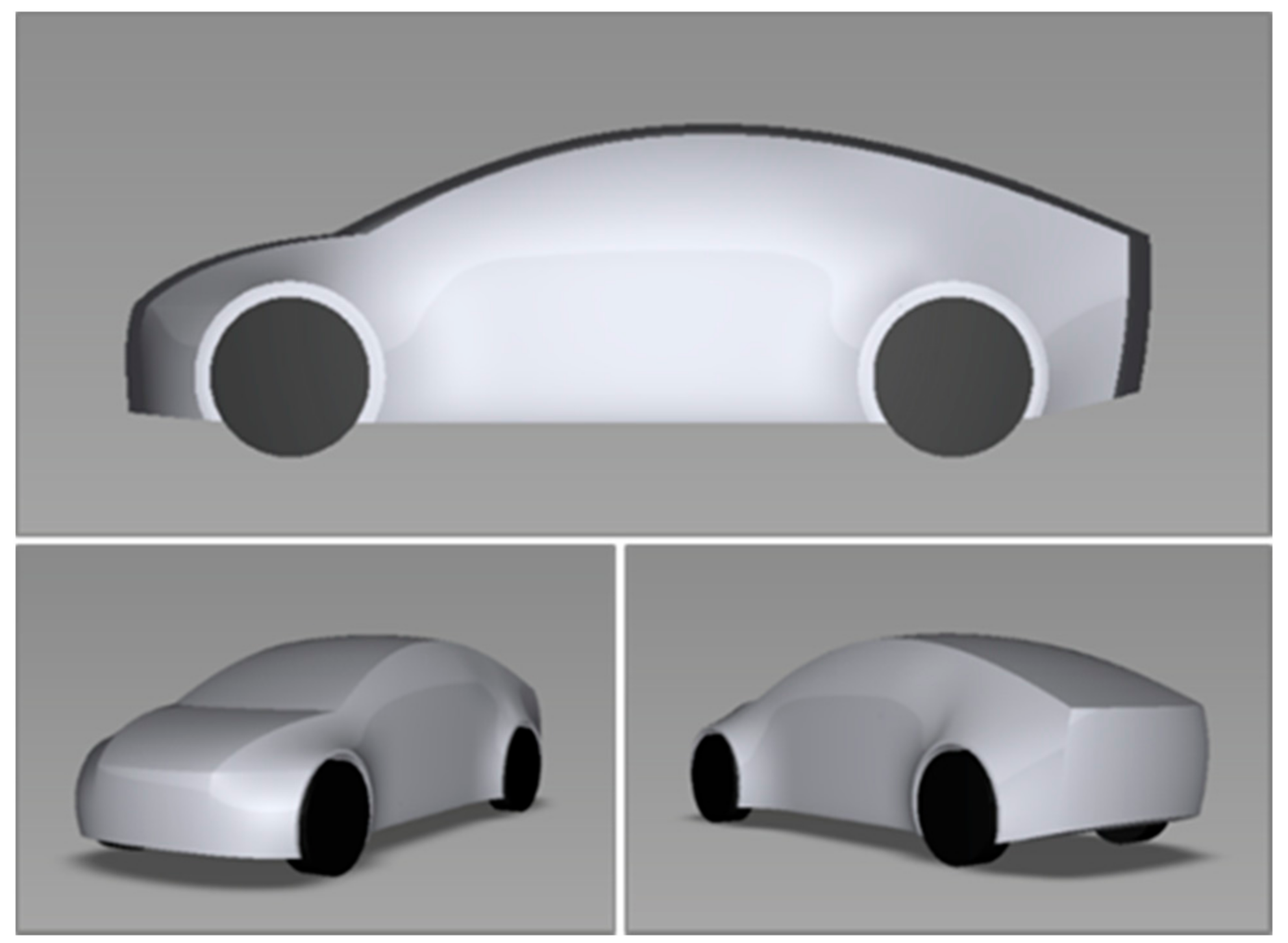
A new test model, shown in
Figure 1, was specifically designed for use in this investigation and designated the “Resnick model” in deference to its designer. The dimensions, proportions, and style were derived from projections made by authors Resnick and Boardman for new C/D segment vehicle targeted for the year 2040 as a time when the adoption of autonomous driving technologies might reach a SAE Level 4 [
49] and which could include organised vehicle platooning. The design concept provided a high-riding coupe/SUV style.
The scale of the wind tunnel models was chosen in order accommodate a range of planned test configurations comprising multiple models within the working section of the wind tunnel. In addition, the experimental test process, as described below, also placed restrictions on the scale of the models. Thus, a scale of 5.5% of the full-scale design was chosen which gave a blockage ratio by model projected frontal area to nozzle outlet area of 0.7% for a single model. The dimensions of each model were length 267 mm, width 108 mm, and height 98 mm.
The design of the wind tunnel models included some simplifications for ease of manufacturing and repeatability, and also as part of the system which was designed for quick re-positioning of models in the working section. The centre-line profile of the original Resnick design was maintained in the scale models and extruded to the full model with as shown in
Figure 2. The main body of each model was machined in high-density tooling foam and sandwiched by laser-cut side panels in MDF which included the wheel representations and hooks to fix into the model location slots of the bespoke ground board panels. Plan-form curvature was not included in the wind tunnel models and the extremities of each side featured sharp-edges.
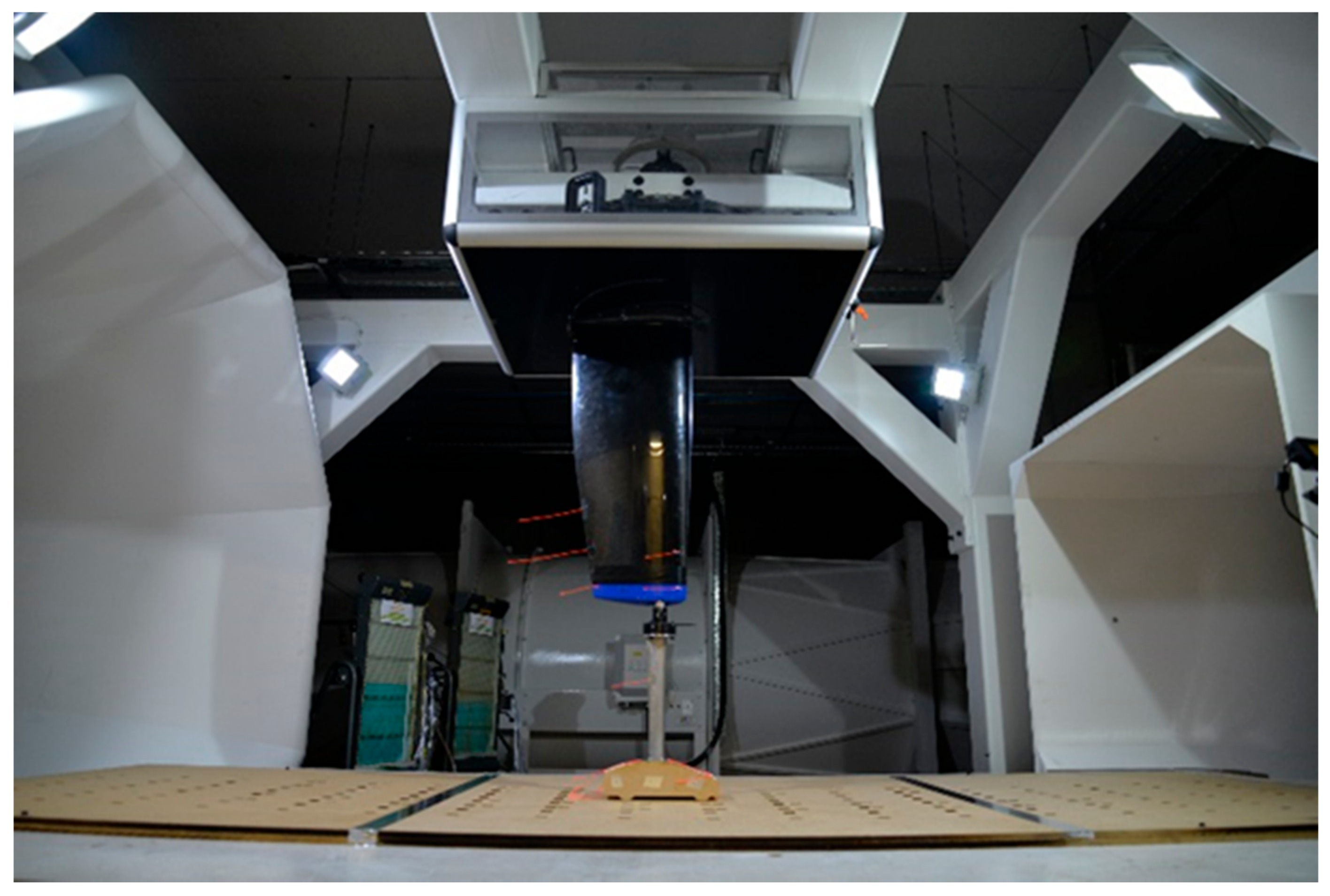
Figure 2 shows the ‘measurement model’, which was attached to the overhead balance throughout the test programme by means of a specially manufactured thin streamlined strut, machined from high-grade steel.
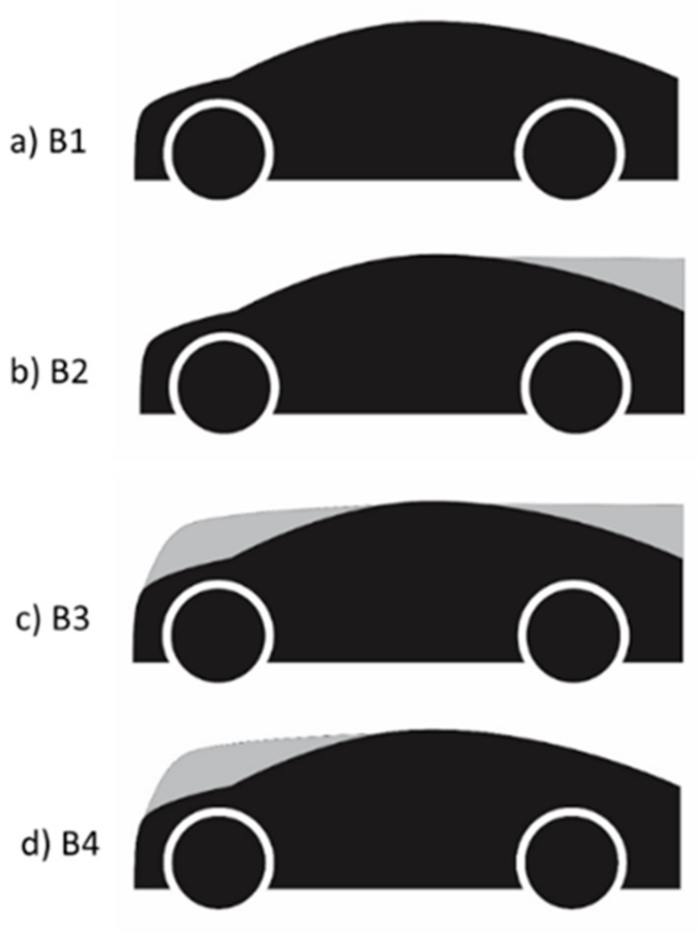
Simulation of the proposed morphing of upper-body surfaces for the wind tunnel models was achieved by the use of removable add-on sections, as illustrated in
Figure 3. These were also NC-machined in high-density tooling foam and attached to the models using aluminium tape. The add-on sections were designed to provide significant changes in geometry in which their forms were perceived to be deployed to match with any given position in a platoon. In
Figure 3a, the B1 profile is the baseline model.
Figure 3b shows the addition of the backlight morphing section (B2 configuration) and was used as the lead model in platoons.
Figure 3c shows the B3 configuration comprising the addition of both the nose and backlight morphed sections which was the configuration proposed for all positions in a platoon other than the leading or trailing models.
Figure 3d shows the B4 configuration of the deployment of only the nose add-on section which was the configuration which was used for trailing models in all platoons.
Neither the overall dimensions nor the frontal area of the models were changed by the use of the add-on body-morphing sections.
The test facility used for this investigation was the Coventry University Low-Speed Wind Tunnel. The wind tunnel is of an open-section, closed-return design. The contraction ratio is 3.63:1 and the maximum jet velocity is 45 ms−1. The nozzle is 1.3 m wide and 1.0 m in height. The length of the working section 2.5 m and the complete circuit length is 34.78 m. The temperature inside the wind tunnel is controlled to ±2 °C by a cooling coil in leg 4. The fan is powered by a 110 kW variable speed DC motor. Nine equally spaced carbon-fibre blades are used in the fixed geometry single stage axial pusher fan. The wind tunnel design includes a removable “staging” fitment which provides a ground plane extending from the nozzle to the collector and creating a ¾ open-jet arrangement. A bespoke 6-component overhead balance system was used for all force and moment measurements.
The wind tunnel configuration allowed for the aerodynamic forces and moments to be measured on a single model in a single fixed position, as shown in
Figure 4. The platoon configurations were constructed by placing the other models around the “measurement model” so that drag data was effectively collected for each model position in each platoon.
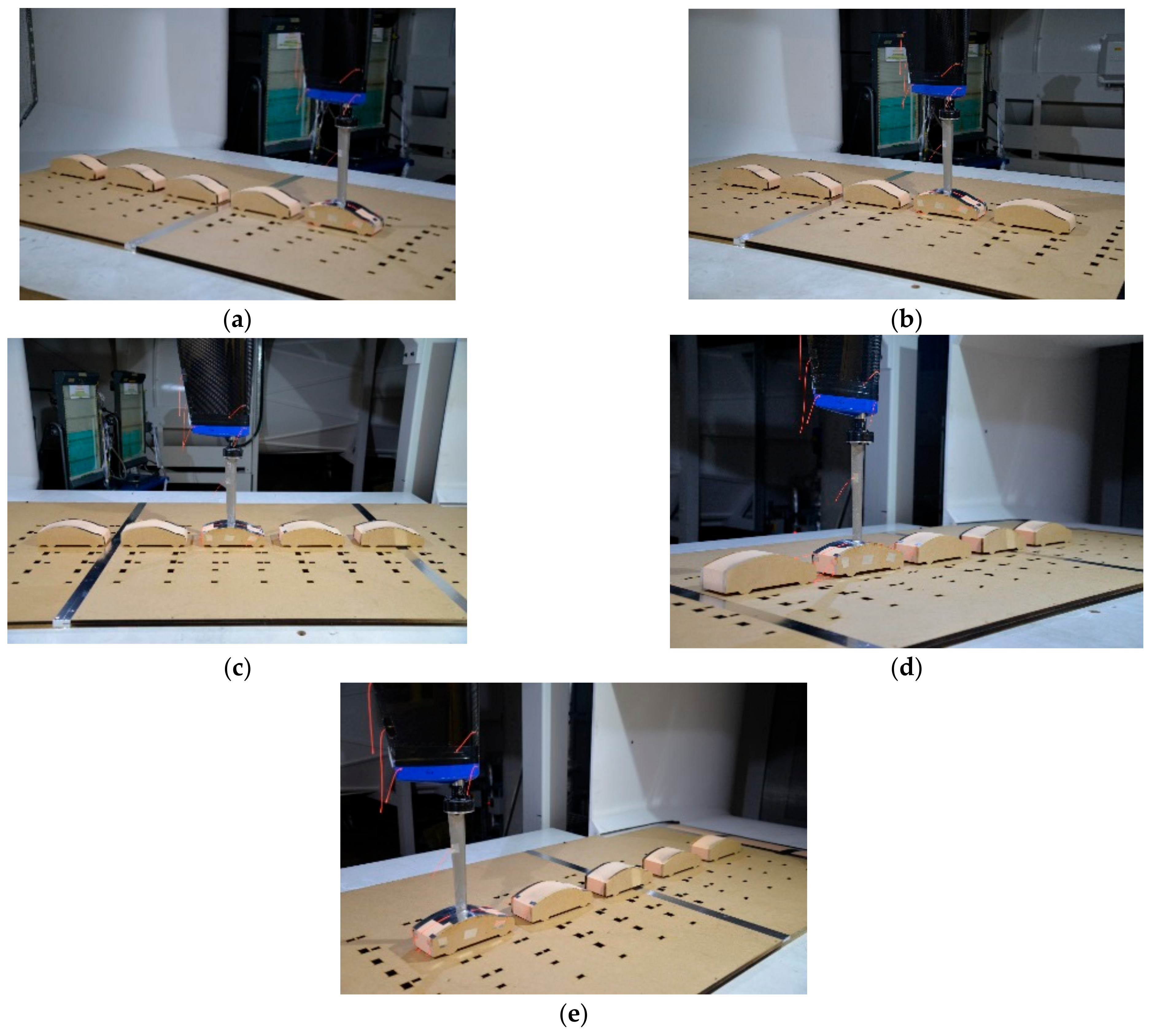
Figure 5 below illustrates the re-positioning of models around the ‘measurement model’ for Configuration 5 comprising the platoon of five baseline models (B1) models.
The fixed longitudinal spacing between the Resnick models was chosen to be 25% of the model length for every configuration. This spacing was chosen on the basis of results shown by Hoerner [
4] and Romberg [
5] to most likely give the greatest drag benefit to bluff-body models in close proximity.
All the wind tunnel tests were conducted at a nominal wind speed of 40 ms−1 giving a Reynolds Number for the flow of Re = 0.07 × 10⁶ based on model length. No corrections were applied to the measured data.
The wind tunnel balance exhibited a good degree of repeatability during these tests and the difference in the measured drag forces between repeated runs gave a maximum difference in the values of the calculated drag coefficient of ±0.002.
3. Results
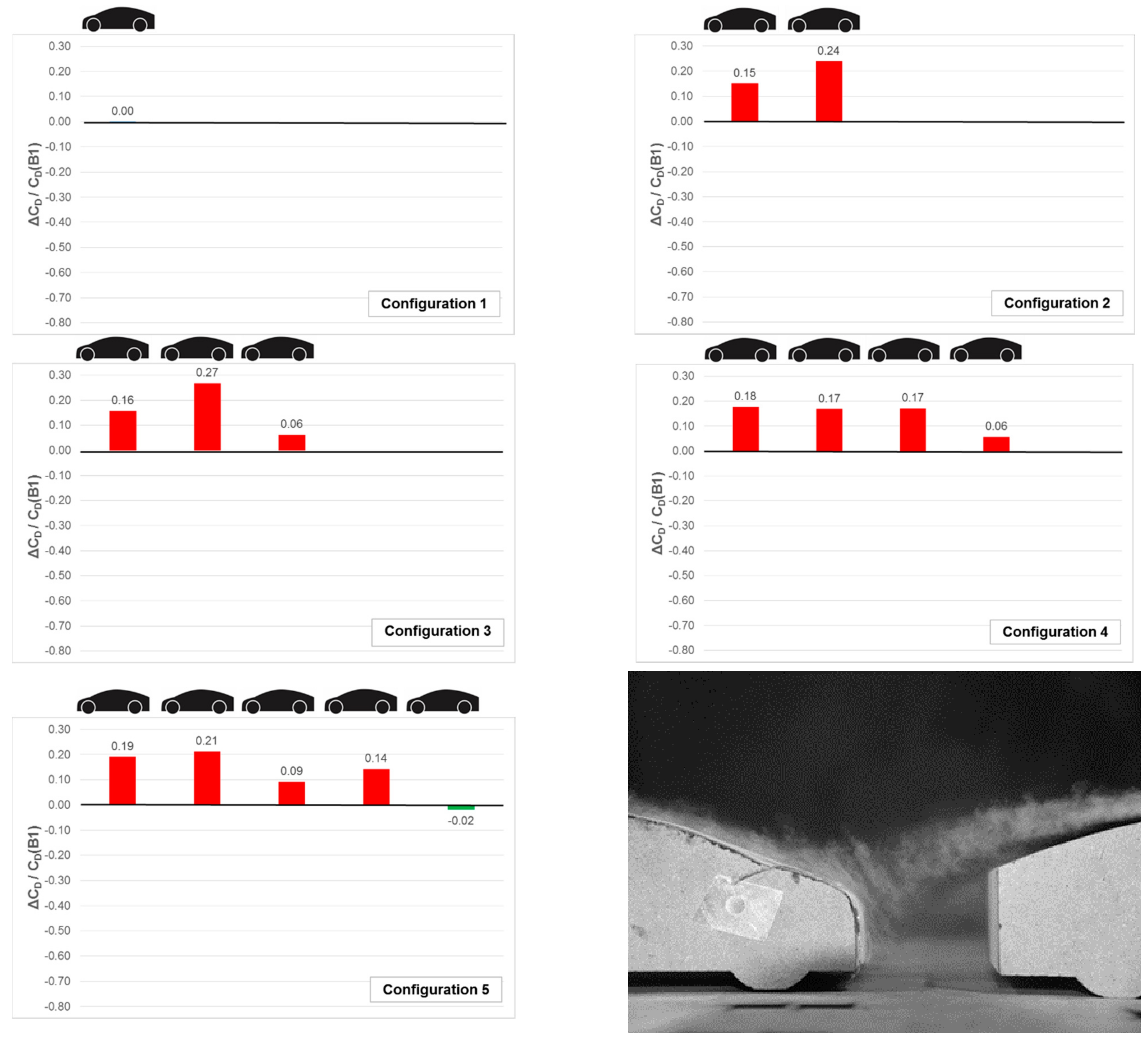
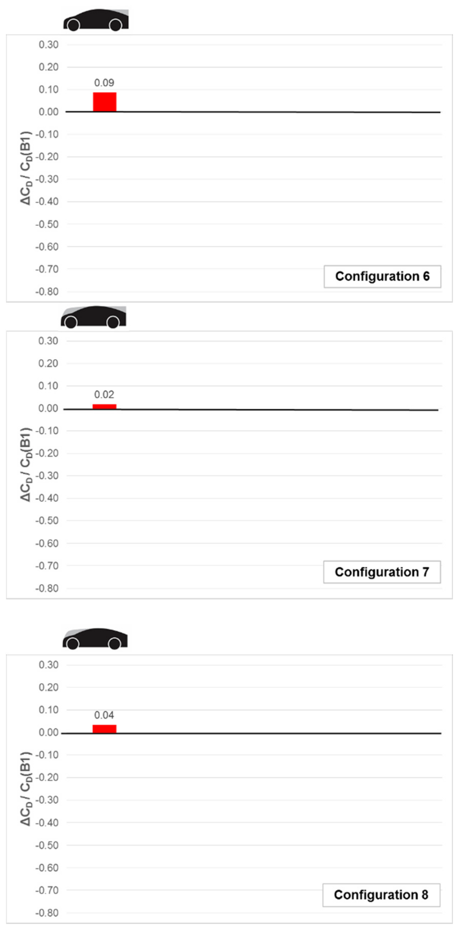
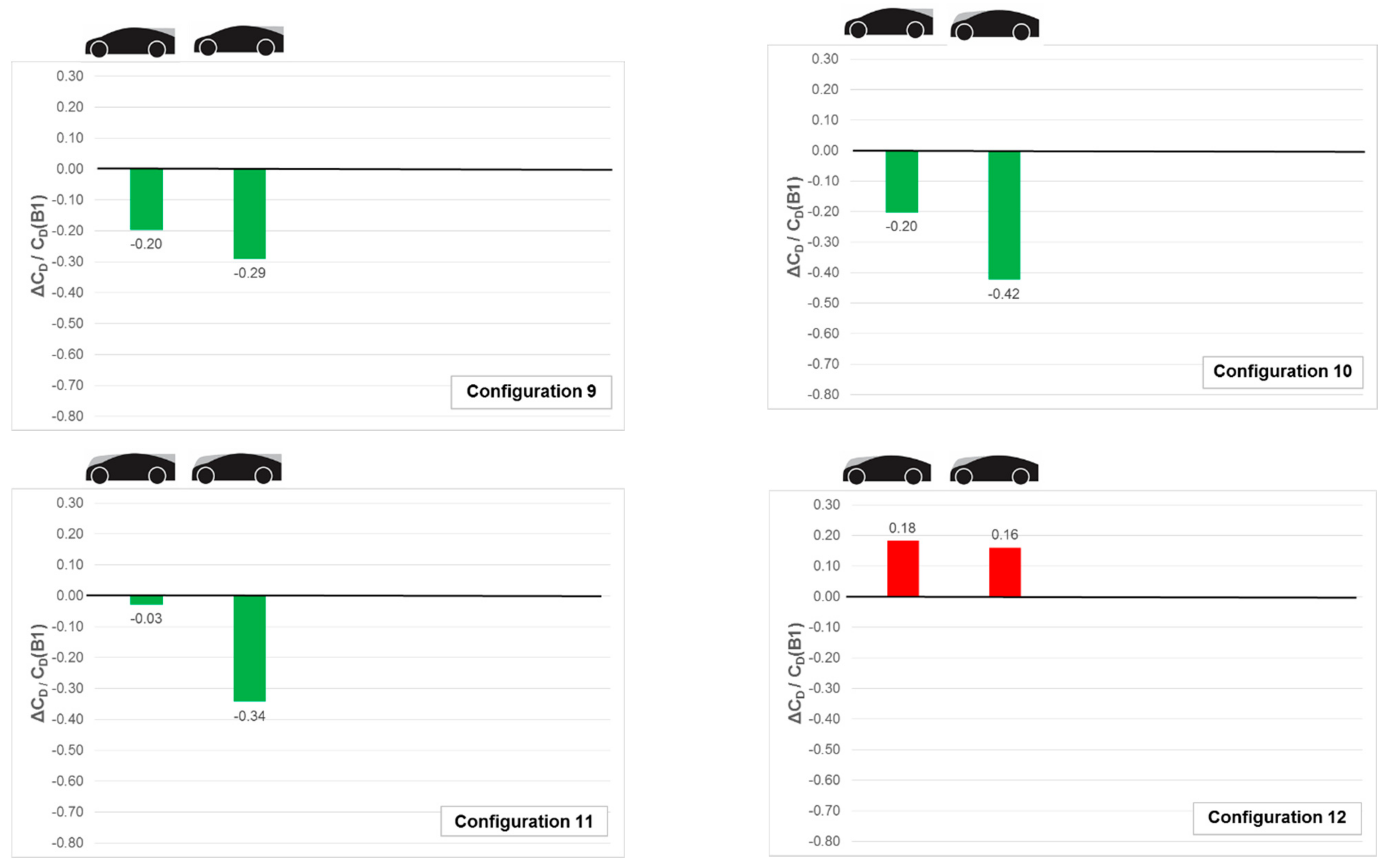
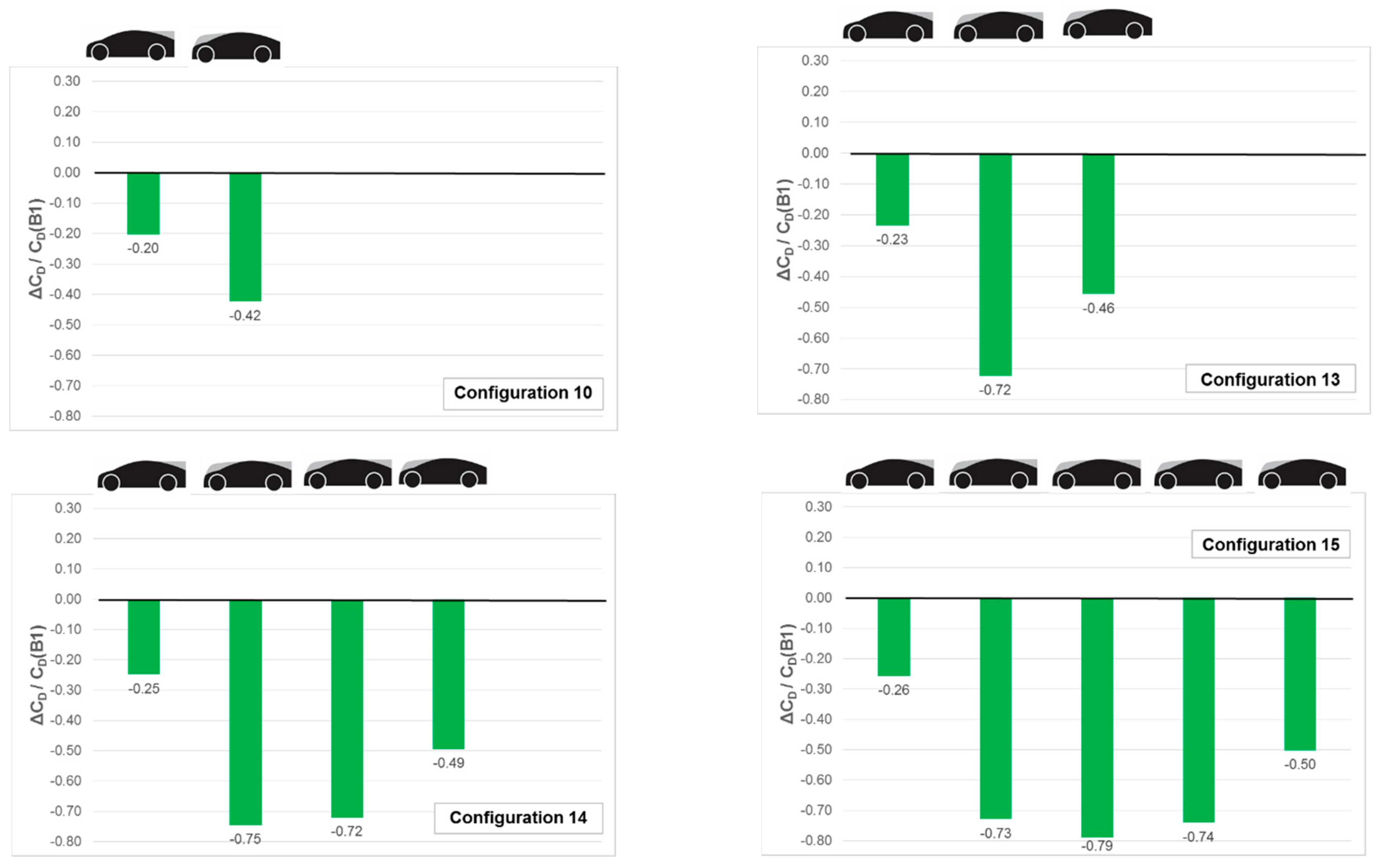
The test results are shown in the bar-charts of
Figure 6,
Figure 7,
Figure 8,
Figure 9,
Figure 10,
Figure 11,
Figure 12 and
Figure 13. For each platoon configuration the change in drag coefficient (ΔC
D) between the baseline (B1) condition and each constituent member is plotted as a separate bar. The drag difference is normalised by the baseline (B1) condition of the Resnick model. A reduction in drag for constituent member, compared to the baseline B1 condition when tested alone, is indicated by a negative value of ΔC
D/C
D (B1) and is shown as a green bar. An increase in drag for a constituent member, compared to the baseline B1 condition, is indicated by a positive value of ΔC
D/C
D(B1) and is shown by a red bar.
Figure 6,
Figure 7,
Figure 8 and
Figure 9 show platoon results from tests conducted with a single line of models and were previously reported in [
50]. They are included in this paper to provide readers with data to compare with the results presented in
Figure 10,
Figure 11,
Figure 12 and
Figure 13. These new bar-charts show results of tests conducted with multiple lines of platoons and novel positioning in plan view.
Figure 6 shows results from wind tunnel tests on Resnick models in the baseline (B1) configuration only. Configuration 1 shows the baseline model alone as a reference. Configurations 2 to 5 show the systematic addition of B1 models to the platoon. The addition of the second B1 configuration model (Configuration 2) resulted in an increase in drag for both the lead and trailing model. The assumption for this result was that no beneficial shielding of the trailing model was provided by the lead model.
Figure 6 right bottom helps confirm this assumption, showing smoke visualisation of the flow in the spacing between the two B1 models of Configuration 2. The flow which follows the form of the backlight of the lead model appeared to be fed onto the nose of the trailing model. This agrees with the suggestions by Hoerner [
4] for streamlined forms as discussed in the Introduction. The increase in drag of the lead model appeared to be due to the trailing model exerting a detrimental influence on the separation of flow from the rear the lead model. There is a suggestion of earlier separation on the backlight rather than at the trailing edge of the upper-body. When a third B1 model is added to the platoon it also experiences a drag increase, but smaller than that of the preceding two models. The trailing model appeared not to influence the performance of the upstream models. By contrast adding the fourth B1 model appeared to even-out the penalties for the second and third models. Adding the fifth B1 model changed the relative performance of the platoon constituents again, but the trailing model was influenced very little by its inclusion.
Figure 7 shows the effects on drag of the front and rear add-on body sections to give the B2, B3, and B4 styles (test Configurations 6, 7, and 8 respectively). For all three styles the add-ons generated a drag penalty when tested alone compared to the baseline Resnick B1 model. The backlight add-on section for style B2 (Configuration 6) increased the size of the base area of the model and hence was expected to also increase the suction on the reward facing surface as well as the resulting trailing separated wake, all of which contributed to the resulting in a drag increase. The nose add-on of style B4 (Configuration 8) provided a taller bluff front-end increasing the front-face pressure drag. Both add-on parts fitted together to create style B3 (Configuration 7) resulted in a small drag increase over the baseline B1 style but a lower drag penalty than for the sum of the individual parts. This result suggested an unexpected beneficial interference effect of the shape changes at both ends of the model.
Figure 8 shows 2-vehicle platoons. For Configurations 9 and 10, the backlight add-on (B2) to the lead vehicle provided drag reductions which appeared to be independent of the form of the front-end of the trailing vehicle. The nose add-on (B4) for the trailing vehicle of Configuration 10 gave a greater reduction in drag than the backlight add-on (B2) for the trailing model of Configuration 9, as would be expected since this arrangement is more likely to direct flow over the trailing model than allow it to impinge on the front screen of the trailing model. The drag reduction of the trailing model in Configuration 9 would appear to be due to the shielding effect provided by the B2 style of the lead model and in doing so to also be greater than the expected drag penalty of the B4-style rear end. For Configuration 11, the combination of two B3 styles in tandem provided drag reductions for both models in the platoon. This was a notable improvement over the B3 style on its own in, as shown in Configuration 7 (
Figure 7) and likely to be due to both the shielding effect of the trailing model and the reduction in negative pressure on rearward facing surfaces of the leading model. Configuration 12 comprising two B4 styles in tandem showed a drag penalty for both models which was greater than for a single B4 style alone. It is likely that this was due to flow regime which produced an increase in pressure drag on the nose of the lead model, a change in pressures on the reward facing surfaces of the lead model and the feeding of air onto the nose of the trailing model. Configuration 10, comprising a B2 style leading a B4 style, as expected, gave the lowest total drag of the 2-model platoon configurations. Overall the results shown in
Figure 8 emphasise the sensitivity of upper-body geometry to the efficiency of 2-model platoons in close proximity and demonstrate that shielding of trailing models is not the only mechanism which helps reduce the drag of individual models. For Configurations 9, 10, and 11, the lead model benefits from the presence of the trailing model—a feature which anecdotally can be observed in high-speed NASCAR racing on ovals in the USA.
Figure 9 shows the development of single-line platoons from 2 to 5 constituents utilising the add-on body sections. The lead model was always specified as the B2 style and the trailing model the B4 style. The centre models comprised the B3 style.
When comparing
Figure 9 to the similar lengths of platoons comprising only B1 styles as shown in
Figure 6 (configurations 2, 3, 4, and 5) the use of the add-on sections matched to specific longitudinal positions, showed significant drag reductions.
For all of the configurations 10, 13, 14, and 15, the lead model shows a benefit which is almost constant regardless of the number of trailing models. However, the benefit of the second model is enhanced with the addition for the third model (configuration 10 to 13), the third is enhanced by the addition of the fourth (configuration 13 to 14) and fourth enhanced by the addition of the fifth (configuration 14 to 15). As with the lead model the individual benefit of the trailing model is also mostly independent of the number of models in the platoon.
The benefit to the performance of the B3-style centre models is very similar in magnitude for configurations 13, 14, and 15.
As with previous comments relating to
Figure 6,
Figure 7 and
Figure 8 the drag reduction for each model is very dependent upon combinations of upper body shapes between consecutive models but the definitive apportioning of effects requires further investigations of flow regimes and body surface pressures.
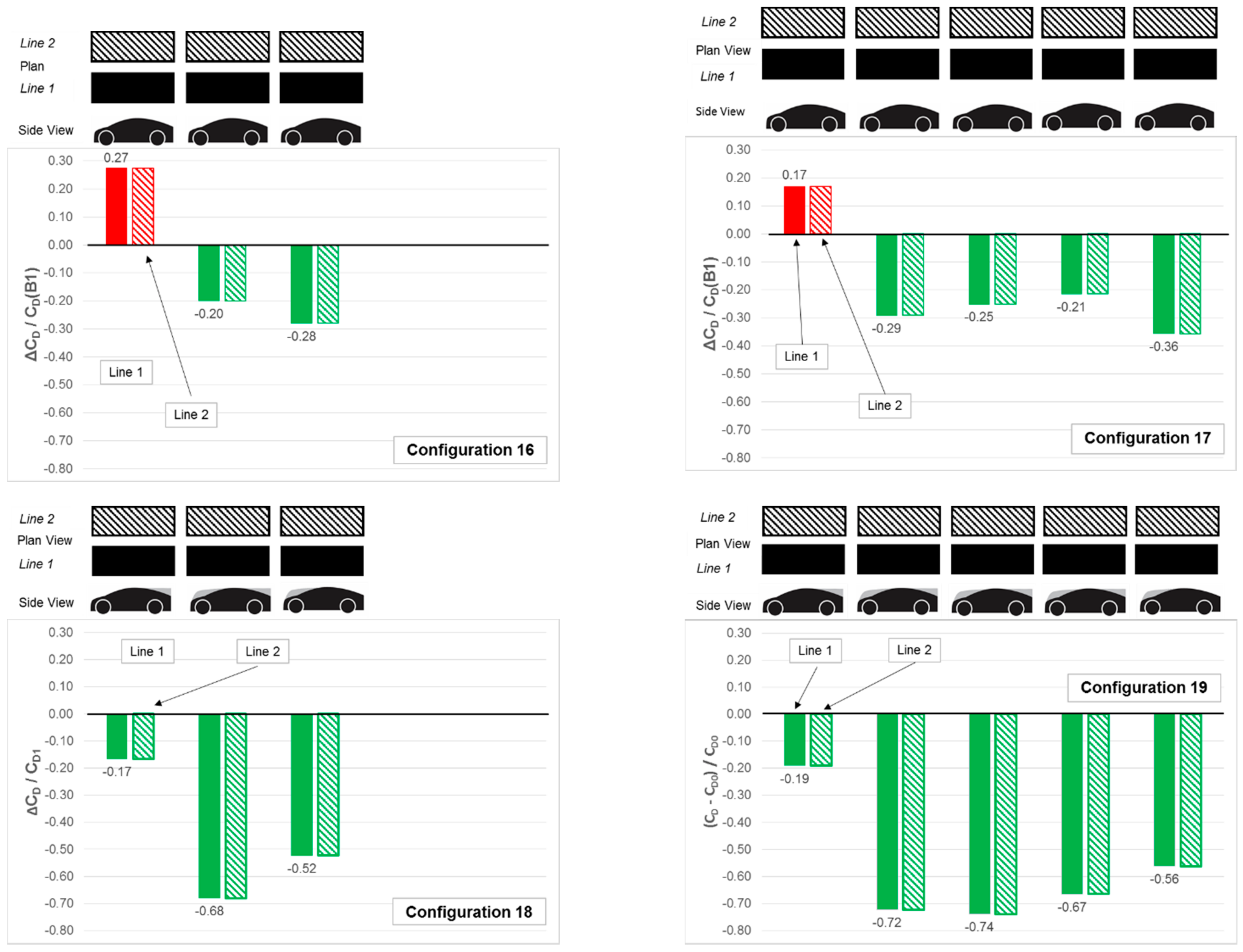
Single-line platoons have been the subject of much of the previously published literature but in this investigation the opportunity was taken to expand the range of test scenarios as a reflection of other potential platoon configurations which could be formed on existing road networks. Thus, wind tunnel tests were conducted using a limited number of “twin-line” and “triple-line” platoon configurations. The lateral spacing of the models in these tests was 50% of the model width.
Figure 10 shows the effects on the drag of individual models compared to the baseline B1-styled model when tested alone for two lines of identical combinations of models with respect to longitudinal position. Configurations 16 and 17 comprised lines of B1-styled models whilst configurations 18 and 19 comprised lines which were led by a B2-style, had a B4-style at the tail and with B3-styles in-between lead and trailing models. For comparison with single-line platoons see Configurations 3 and 5 of
Figure 6 for B1-style models and configurations 13 and 15 of
Figure 9 for B2/B4/B3-style combinations.
First of note is that with the exception of the lead models, Configurations 16 and 17 showed drag reductions for all trailing models. In contrast the for the respective single line cases, all models had shown drag penalties. The rearmost models of Configurations 16 and 17 showed the greatest benefit in drag-reduction for the twin-line arrangements.
The use of the add-on upper-body sections in Configurations 18 and 19 produced drag reduction profiles and magnitudes, with longitudinal position, which were similar to those produced by the single-line platoons of the same model upper body geometries.
Thus it could be suggested that curvaceous upper-body style of the B1-style models in twin-line platoons might have resulted in flow regimes which provided more lateral interference between the lines than was the case for the B2/B3/B4-styled platoons. This is another feature which requires further investigation.
With three-lane motorways being common in the UK, wind tunnel tests were also conducted to investigate the potential effects on drag of “triple-line” platoon configurations as shown in
Figure 11 below. As for the twin-line investigations tests were conducted with lines consisting of 3 and 5 models and both as homogenous platoons of B1-style models and platoons of combinations of B2-leads, B4-trailing models, and B3 centre models.
Configurations 20 and 21 can be compared with Configurations 3 and 5 of
Figure 6 and also Configurations 16 and 17 of
Figure 10.
Configurations 22 and 23 can be compared with configurations 13 and 15 of
Figure 9 and Configurations 18 and 19 of
Figure 10.
For Configurations 20 and 21 for the B1-styled models, the lead models experienced a drag penalty, as seen with the twin-line versions, but the lead model in the centre-line (line 2) had a very much reduced drag penalty compared to the lead model in the outer lines. This is a further feature that requires investigation but the suggestion for this result is that lateral proximity effects were giving rise to greater flow angularity in plan and that the sharp outer edges of the models gave rise to more signification separation on the front corners of leading models than seen with the single and twin-line platoons. The leading-edges of the centre line (line 2) leading models may have experienced a much-reduced angle of approach flow around the front corners compared to the single and twin-line platoons. It was also found that for the centre (line 2) models, from the second position in the platoon to the rear, experienced a significantly greater drag reduction than those in the outer lines (1 and 3). As with the lead models, some of this drag reduction might be due to reduced edge effects of the front corners but requires further investigation to provide confirmation.
Configurations 22 and 23 show more even benefits across rows for the models fitted with the upper-body modifications. The magnitudes of the individual model drag reductions were similar to those of the twin-line Configurations 18 and 19. It was suspected that with the upper-body modifications effectively filling-in more of the gaps between the models that the lateral interference effects were minimised.
The triple-line test series also included the opportunity investigate other platoon configurations.
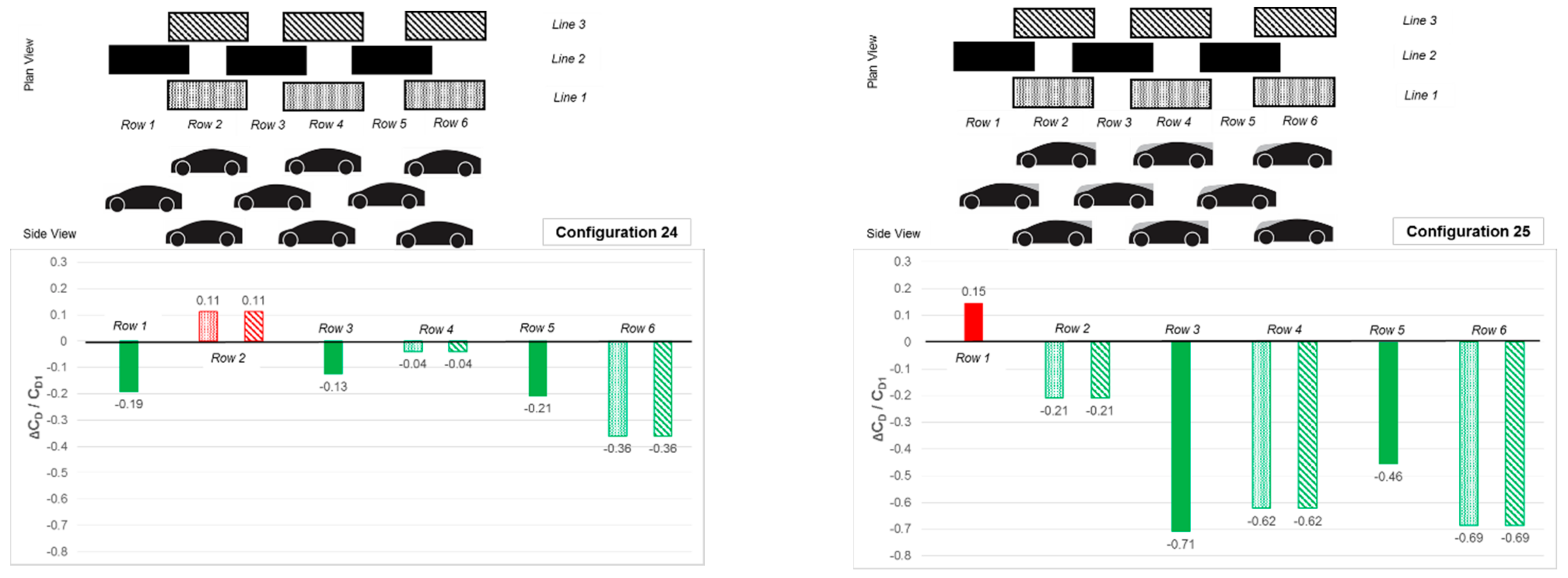
Figure 12 shows the results of a “staggered” 3-line platoon of 9 models with the centre line being 0.5 times the model length ahead of the outer lines 1 and 3. Configuration 24 shows the homogeneous triple-line stagger comprised of B1-styles (for comparison with Configuration 20—
Figure 11) and Configuration 25 comprising B2/B3/B4-styles (for comparison with Configuration 22—
Figure 11).
The upper body geometry appeared to be responsible for the effects observed by comparison of the drag benefits and drag penalties of Configurations 24 and 25, and particularly by comparing the effects on drag of the lead and trailing models on the centre line (line 2). However, there would also appear to be some effects of flow angularity in plan. Again, the addition of the upper-body add-on sections gives a significant enhancement of the platoon performance compared to the homogeneous B1-styled platoon.
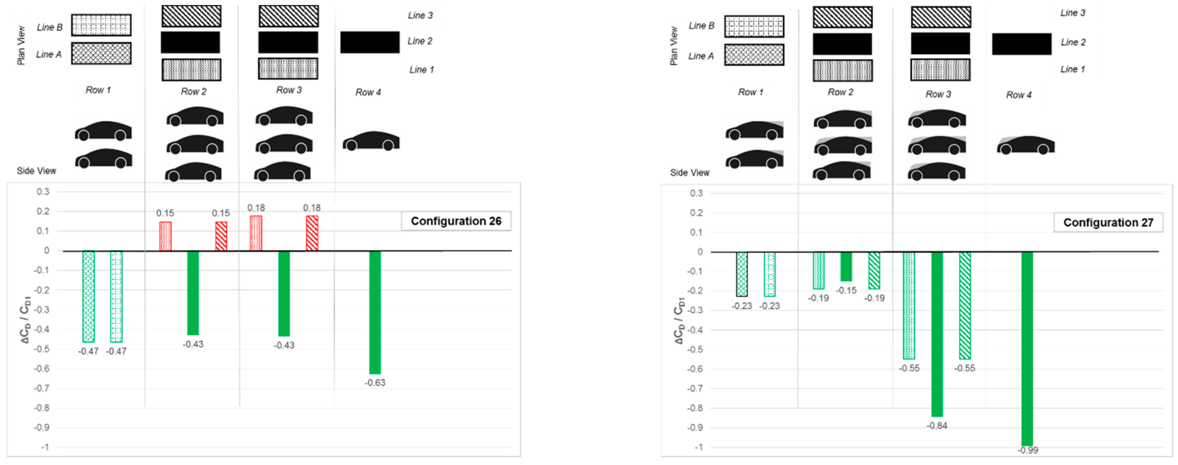
Figure 13 shows results of a Triple-Line test with two leading models “off-set” (in Lines A and B) from the conventional three parallel lines (lines 1, 2 and 3). As with the Triple-line Stagger configurations the use of the B2/B3/B4 upper-body styles (Configuration 27) gave an enhanced platoon drag-reduction performance compare to that using the B1-style alone (Configuration 26). However, the lead models in lines A and B in Configuration 26 experienced a drag reduction compared to the B1-style alone whilst the B2-styles of the lead models in Configuration 27 experienced a drag penalty, implying that the offset is enough to warrant a change back to the B1-style for an optimum geometry. This might also be true of the centre model in row 2, although the geometry for the centre model in row 3 of Configuration 27 might reduce the benefit.
4. Discussion
The main premise behind the investigation described in this paper was that: the flow regimes produced by conventionally optimised low-drag passenger cars may not yield drag reductions when operating in the close-proximity situation of platooning. Indeed, such formations might yield drag penalties and increased energy consumption rather than energy savings.
Using the new Resnick reference model to represent a future connected and autonomous vehicle design and which was based on a projection of future styling trends, a number of platooning configurations have been considered in order to assess the influence of upper-body style on aerodynamic drag-saving potential. Three form changes to the upper-body style were considered to be potentially capable of being achieved through large-scale active morphing techniques, and thereby “tuned” to potential driving scenarios.
The first important point to recognise in this work is that its aim was to be indicative rather definitive and to give some direction for future and more extensive investigations. So while the use of small-scale models in a restricted size of wind tunnel limited the absolute fidelity of results and that to some extent the experimental technique was not ideal, it has provided a comparatively rapid means to gaining a wide understanding of platooning complexities and provided for a long list of potential detailed follow-on investigations.
Considering the wind tunnel test technique, the use of small-scale models always presents the uncertainties surrounding Reynolds Number effects. To this end the authors have attempted to simplify the configurations by making the models of effectively two-dimensional form, i.e., with no planform shaping at this stage and by avoiding radiused edges. All tests were conducted at 40 ms−1, the highest wind speed possible for sustained use in the given facility. The use of a single measurement model attached to the overhead balance does have the advantage of ensuring that all measurements are conducted in the same position within the working section volume, but significantly increases the test complexity and duration by requiring the other models to be repositioned in the wind tunnel so as to obtain measurement data for every platoon position. This requirement of repositioning of models also effectively limited the size of the models due the constraints of the size of the working section in the wind tunnel. To have attempted to assess the effect of model spacing at the same time would have further compromised the scale of the models again due to the fixed dimension of the working section as well as requiring a significant increase in test time. The choice of longitudinal spacing of 25% of model length and lateral spacing of 50% of model width was considered to be at the extreme end of practicality but was also shown in previous publications to be likely to offer the most significant effects and thus considered a useful starting point for this scoping investigation.
A further disadvantage of using small-scale models was that they were too small to enable the accommodation of surface pressure tappings, thereby limiting measurements to forces and moments. Flow visualisation techniques were also limited by fidelity issues with the size of the smoke wand compared to the models so that the authors decided to concentrate on physical measurements within the scheduled test time.
One of the challenges in this work was the extensive test planning required for the movement of every model in order to ensure that the measurements were captured for every effective position in each of the platoon scenarios for both the baseline B1-style only configurations and those which included the more complex arrangements of B2/B3/B4 upper body-shape variations with position.
The choice of the presentation of results in a simple bar-chart format was made for ease of comparison between configurations. The authors had considered other options and had viewed the techniques used by others such as multiple variable techniques used by those investigating the close-proximity effects of cylinders. However, the bar-chart technique was preferred for simplicity and was used in a slightly different format to create some animated overlays for presentations which helped emphasise the variations in performance of individual models due to upper-body geometry.
Of the many questions discussed by the authors in the planning of this work was which configurations to test. Single-line platoons of varying shapes were the obvious starting point, but the authors wanted to extend the range of possibilities based on current road configurations and also begin to explore the possibilities for variances in configurations which might be possible under fully connected and autonomous conditions. This led to some freedom in the design of platoon configurations (effectively in plan view) which were hoped might yield aerodynamic advantages and would then need to be facilitated by both design (styling) or infrastructure arrangements. In this respect the list of possible test scenarios grew rapidly beyond the available test time but in common with the tone of the current challenges for the engineering of autonomously controlled vehicles, the question of how many scenarios would be required to cover every platooning opportunity was extremely difficult to answer. It was obvious that this investigation would only be able to give a small indication of possibilities but has led to on-going research at Coventry University.
The authors were also mindful that the results shown here are for a very specific test environment of steady-state measurement in a zero degree yaw on-set flow regime. It was always recognised that this placed a limit on the applicability of the results and that future work would be required to increase the levels of real-world on-road simulation with on-set yawed flows, unsteady winds and moving ground simulation. However, this increase in complexity from a simple basic method is exactly the same evolutionary process as has been achieved with passenger car aerodynamic test and simulation techniques. Some preliminary yawed on-set flow studies were undertaken but were limited by availability of test time and require further work. The real-world studies of McAuliffe [
51], for example, are indicative of the scenarios which will need to be included in a larger database for platooning configuration development.
There remain many other questions and challenges to be solved in terms of practical applications such as: the formal and informal organisation of platoons, the issues associated with joining or leaving platoons, the control instrumentation and ability to “recognise” a platoon scenario and the systems required to activate the most suitable morphing geometry for an individual vehicle’s position. The ability to apportion energy costs/usage to members of a platoon is a pre-requisite in order for this strategy of travel to be adopted. However, this technology is probably close to being a practical possibility with further development of systems which already exist for the monitoring of commercial vehicle fleets.
The aerodynamic force results presented in this paper provide a numerical evaluation for the changes in upper-body geometry, but additional investigations are required to fully explain the reasons for the changes. As previously mentioned the small-scale limits further practical measurements but the authors are keen to use the capabilities of computational analysis to provide additional data and visualisation as has been recently undertaken to enhance the findings of other wind tunnel tests undertaken in this funded investigation [
52].
The choice of large-scale body morphing as the technique for changing the shape of the vehicles within the platoon was based on the initial perception of the benefits of platooning arising mostly from the shielding of vehicles from the on-set flow by a leading vehicle. Whilst this represents part of the effect, the upstream effect of a trailing vehicle on the flow regime and subsequent pressures on the tail of a leading vehicle can also be significant and given that for vehicles travelling alone much of the drag is attributable to separation effects at the rear of the vehicle, this can be even more significant than the shielding benefit, as shown by Le Good [
52]. Large-scale body morphing remains a practical design challenge for future vehicles, but it is intended that future work will also investigate the practicalities of more conventional active aerodynamic devices in providing the degree of ‘effective’ upper-body shape changes required as implied in the results presented. Such technology also would require a change in control strategy since traditional active devices are mostly controlled on the basis of measured road-speed. The large-scale body morphing and active devices utilised in platooning optimisation would require more complex operational control with the need to be able to take account of vehicle positioning within a platoon configuration, the shape and positioning of surrounding vehicles, and also local and ambient wind conditions.
For future consideration also remains the question of suitable aerodynamics test and simulation capability. As included in the Introduction section of this paper, all automotive full-scale and model-scale wind tunnels have been designed with the aim of testing and optimising single vehicles assumed to be travelling alone although a limited number have added systems to simulate the presence of vehicles upstream of the test vehicle. Computational techniques have followed experimental practices and were developed through correlation work of tests on single models. As a result, there is yet to be a known capability which can ideally cope with tests on multiple vehicles (or scale models) in wind tunnel working sections or validated/correlated CFD techniques which predict incidences of multiple vehicle interferences. It is considered unlikely that full-scale facilities will be built or adapted specifically for platooning studies, but the possibility of the use of large-scale models in full-scale tunnels or track testing might be considered suitable for development work and the provision of correlation data for CFD studies. However, the provision of suitable test and simulation capability remains a need in support of aerodynamic optimisation of platooning configurations.
The results presented in this paper give an indication of what might be achieved in terms of aerodynamic performance and have also highlighted the need for continuing the research interest at Coventry University. However, this topic remains a “big data” project and would benefit from the co-ordination of work by many research teams to build usable data sets for use by the connected and autonomous vehicle community and with whom the road vehicle aerodynamics community will need to work closely.
5. Conclusions
The concept of vehicle platooning can offer opportunities in energy-saving for passenger cars. However, if those energy savings are to be realized, the organisation and formation of the platoons needs to take vehicle shape into account as one of the two main performance variables, the other being the more common subject of published investigations—vehicle separation. However, the variety of passenger vehicle shapes and sizes makes this variable rather more complex to investigate than vehicle separation. Ultimately platooning performance will need to take account of both variables simultaneously requiring extensive investigation programmes.
One potential issue for the shape variable in platooning is that an optimised style for low-drag vehicles considered alone, as is the conventional test case for aerodynamic development processes today, may not be the optimum for platooning. Further, the vehicle alone low-drag optimum might actually result in drag penalties when such shape configurations are grouped in platoons.
The investigation reported in this paper shows the drag contributions of passenger vehicles in a variety of possible platooning configurations and illustrates that consideration of shape, and the potential application of large-scale upper-body morphing, could help achieve worthwhile energy savings.
