
A Review on Process and Practices in Operation and Design Modification of Ejectors


Abstract
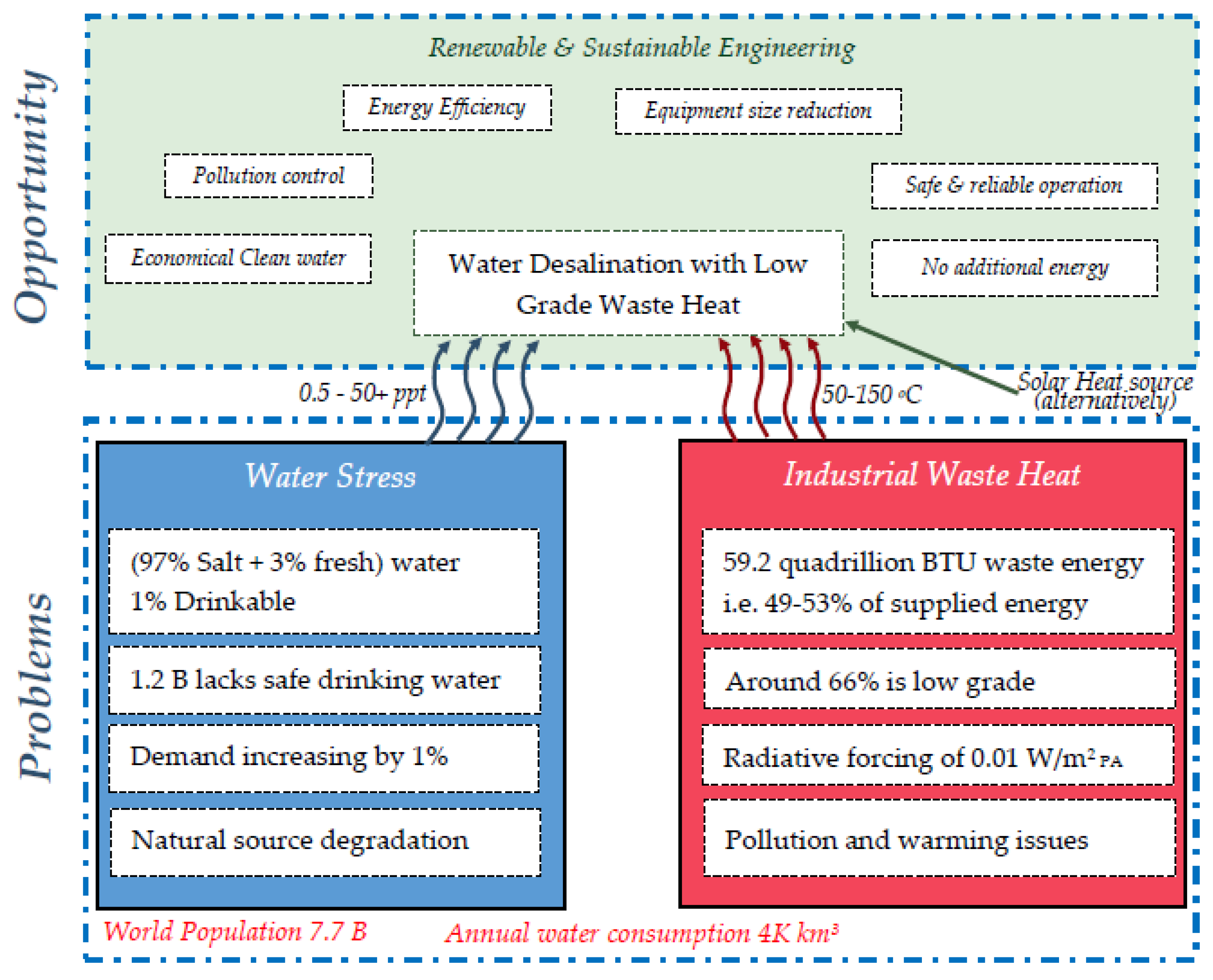
:1. Introduction
2. Ejectors
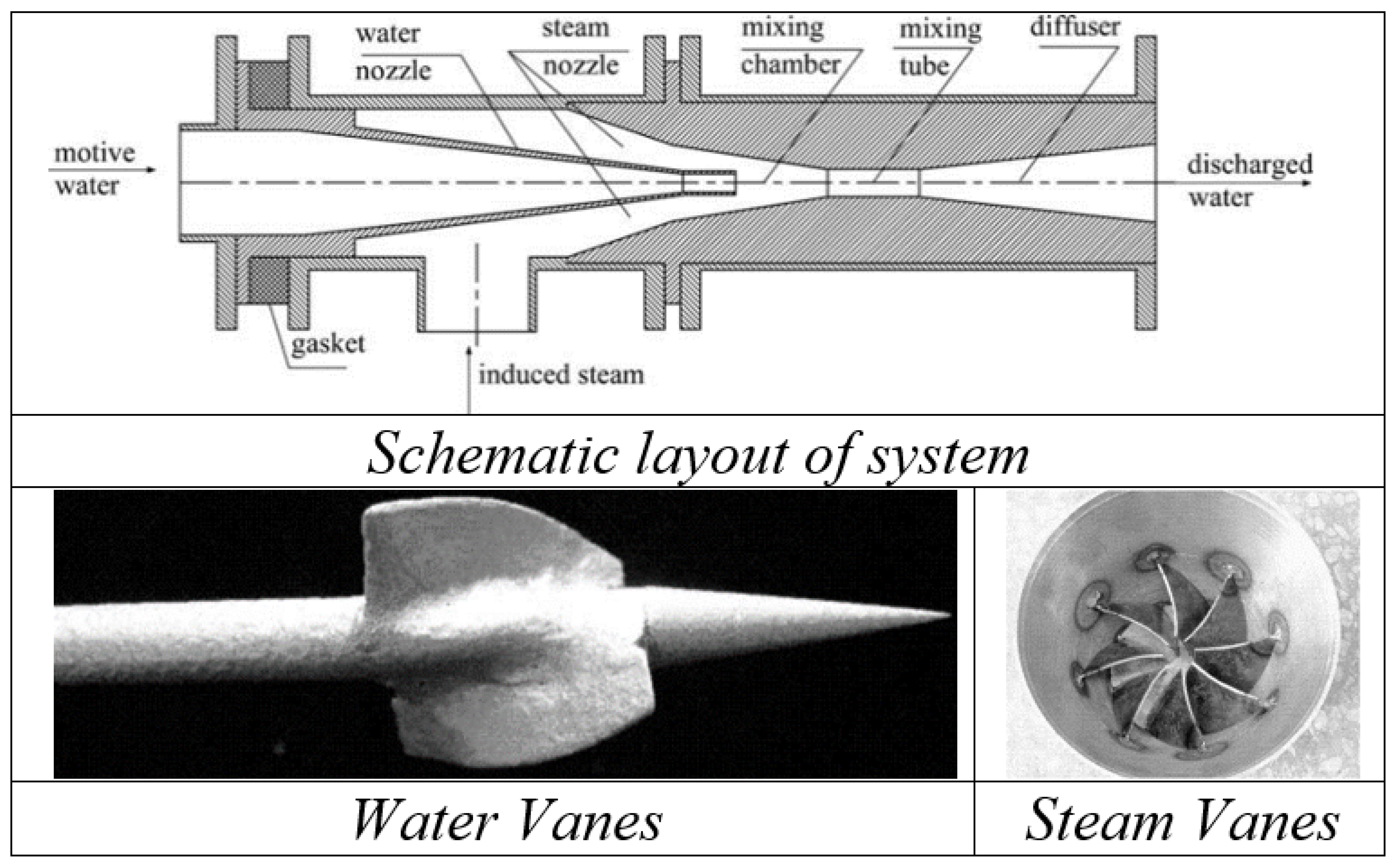
2.1. Construction
2.2. Applications
2.2.1. Vacuum Pumping and Degassing
2.2.2. Power Cycle
2.2.3. Other Applications
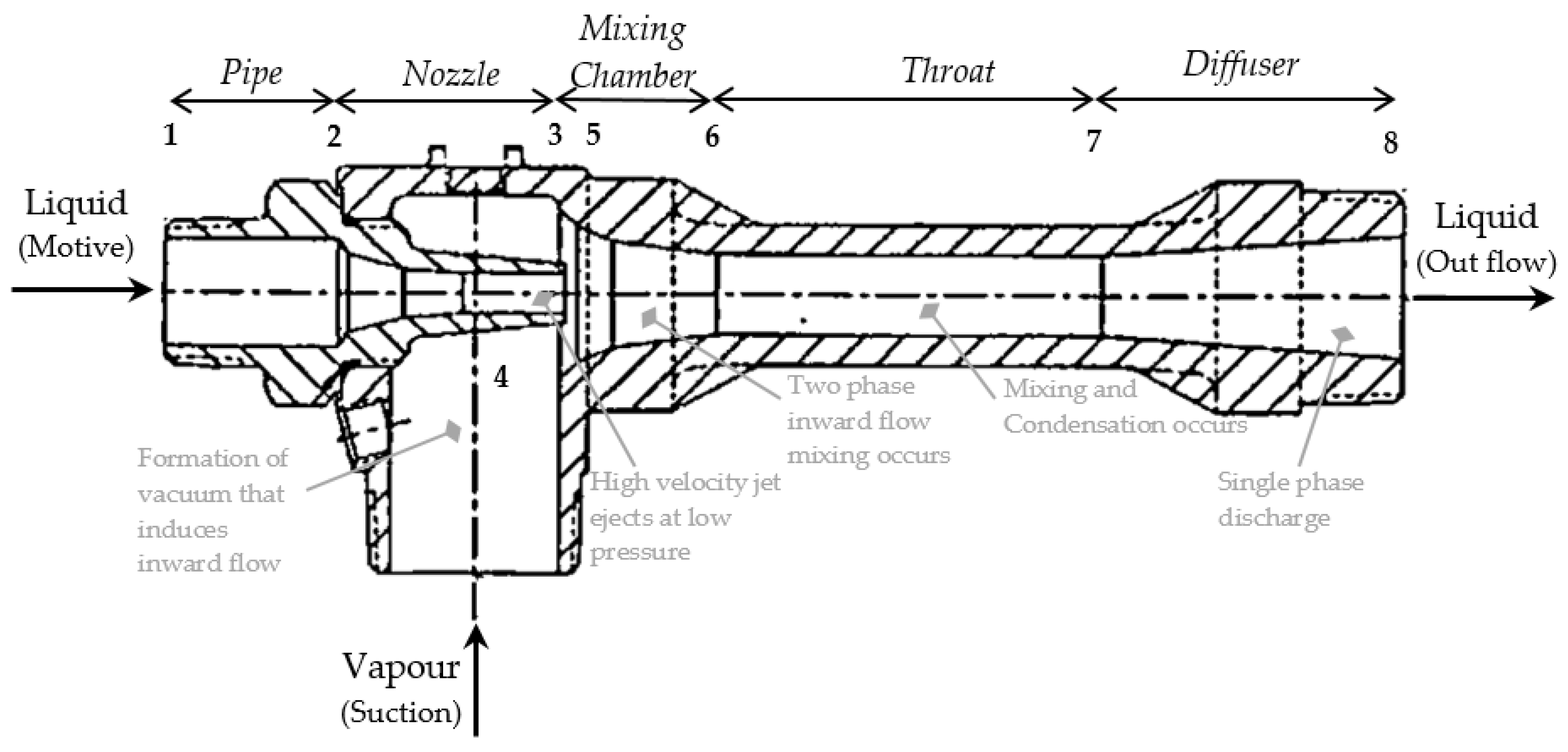
2.3. Operational Principle
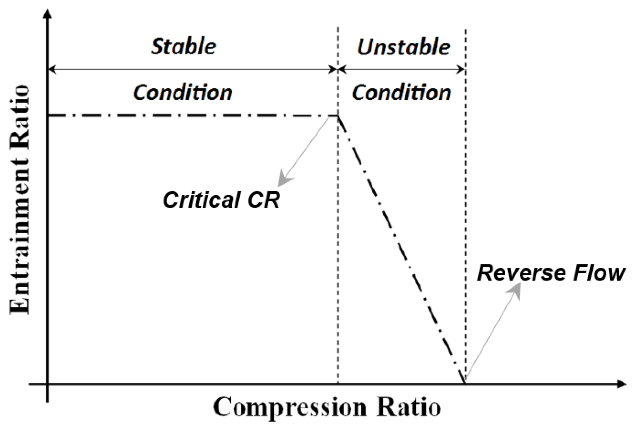
2.4. Performance Estimation Parameters
3. Design Modifications of Ejector
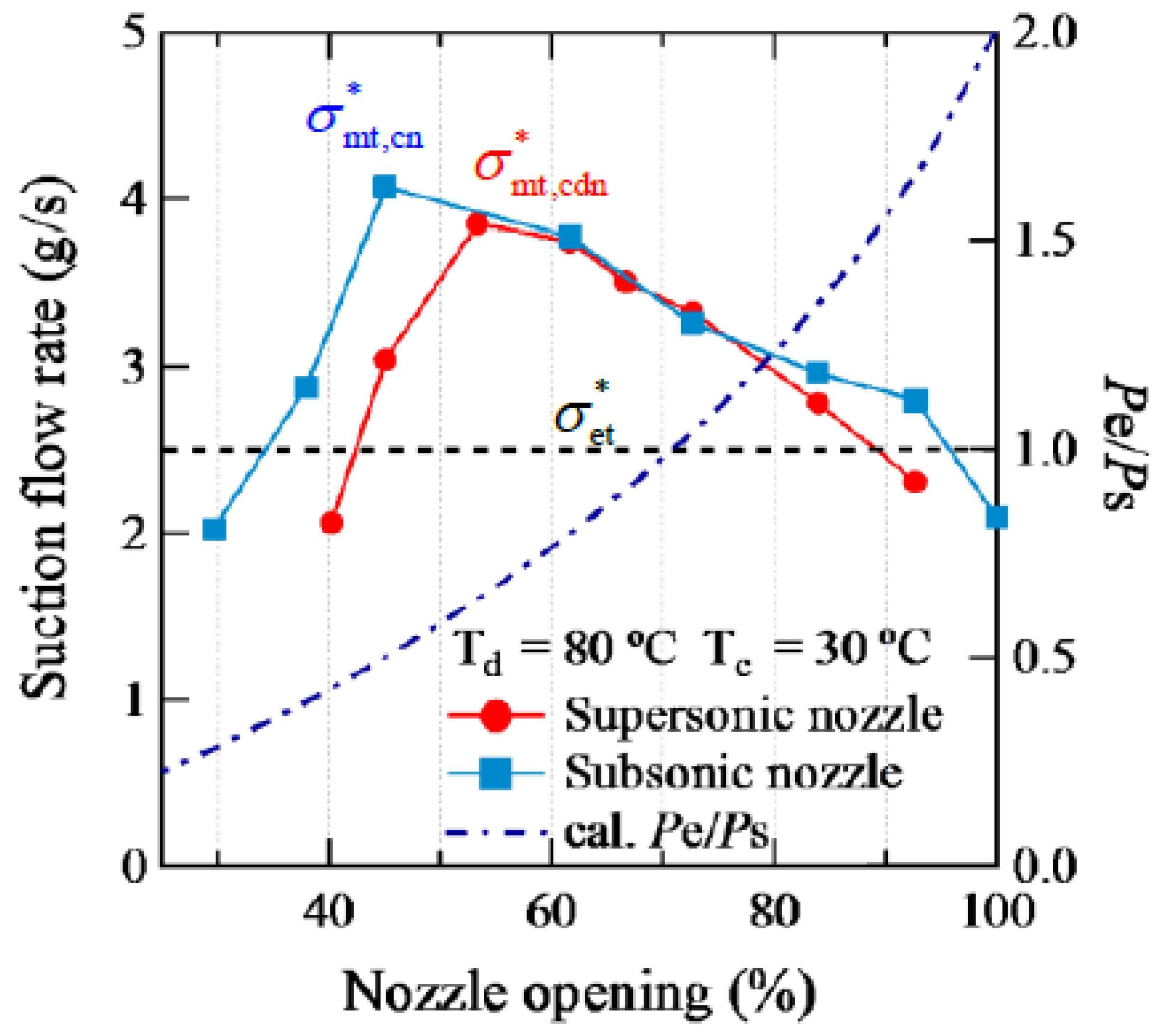
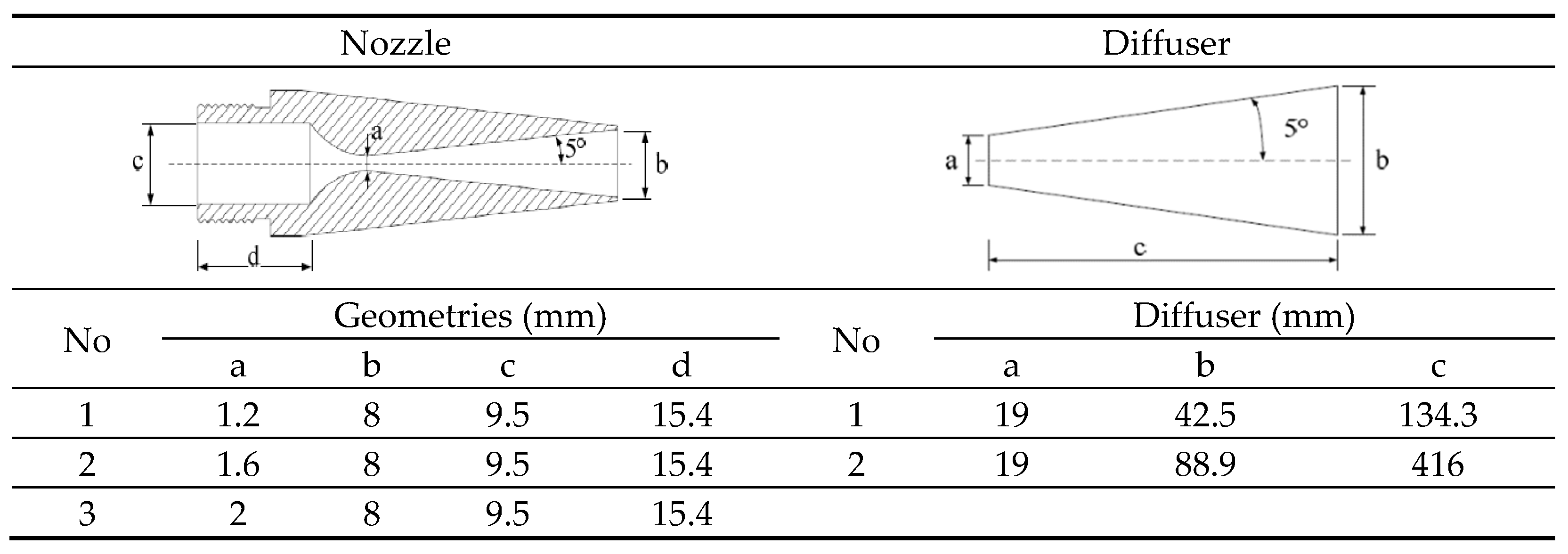
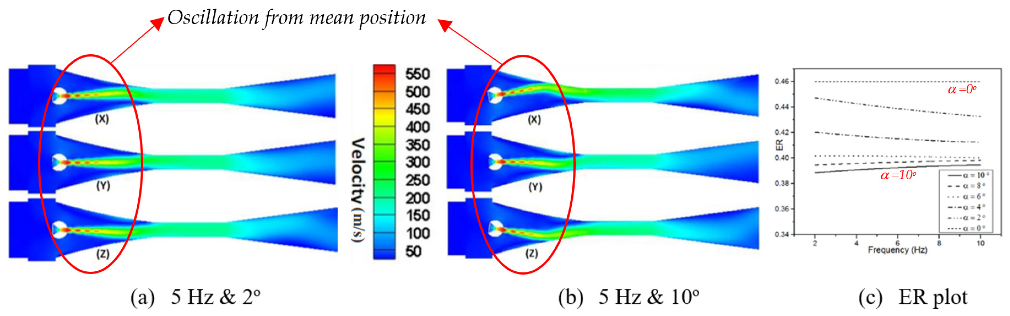
3.1. Nozzle
3.2. Primary Nozzle Position
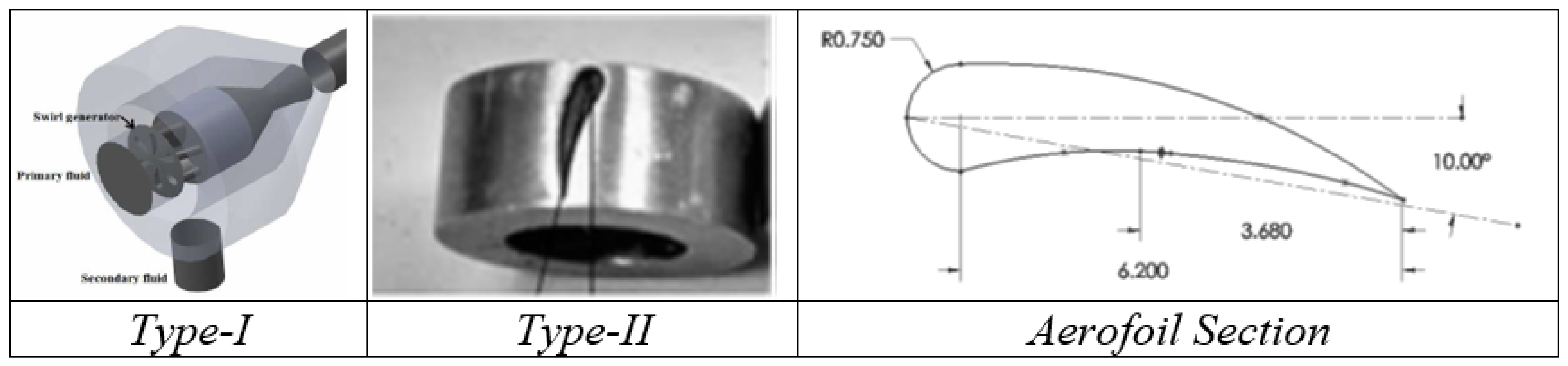
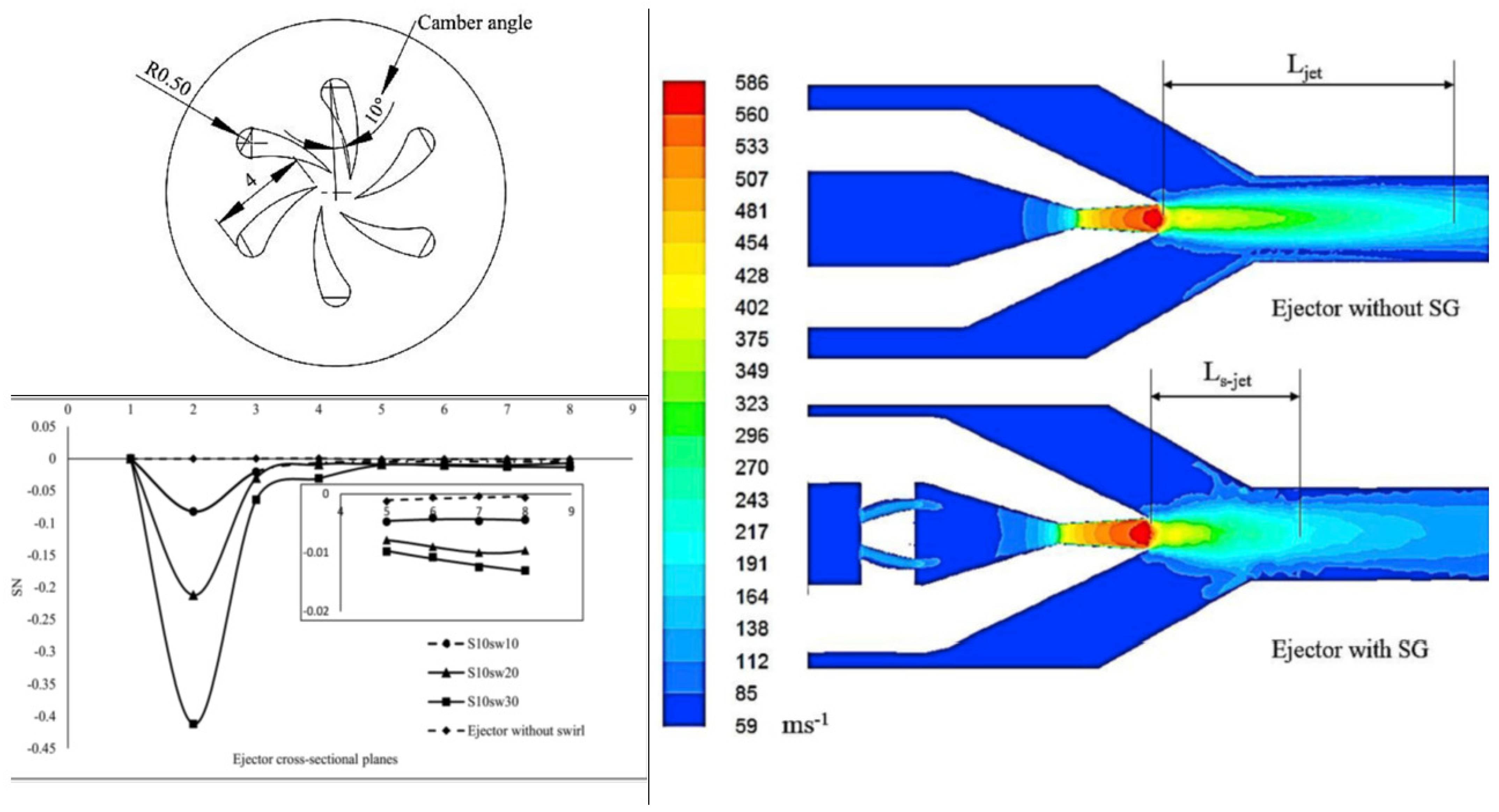
3.3. Inlet Swirling Vanes
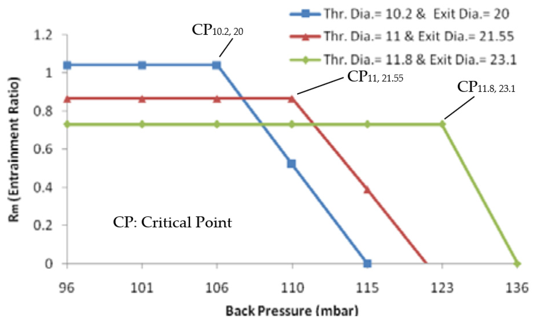
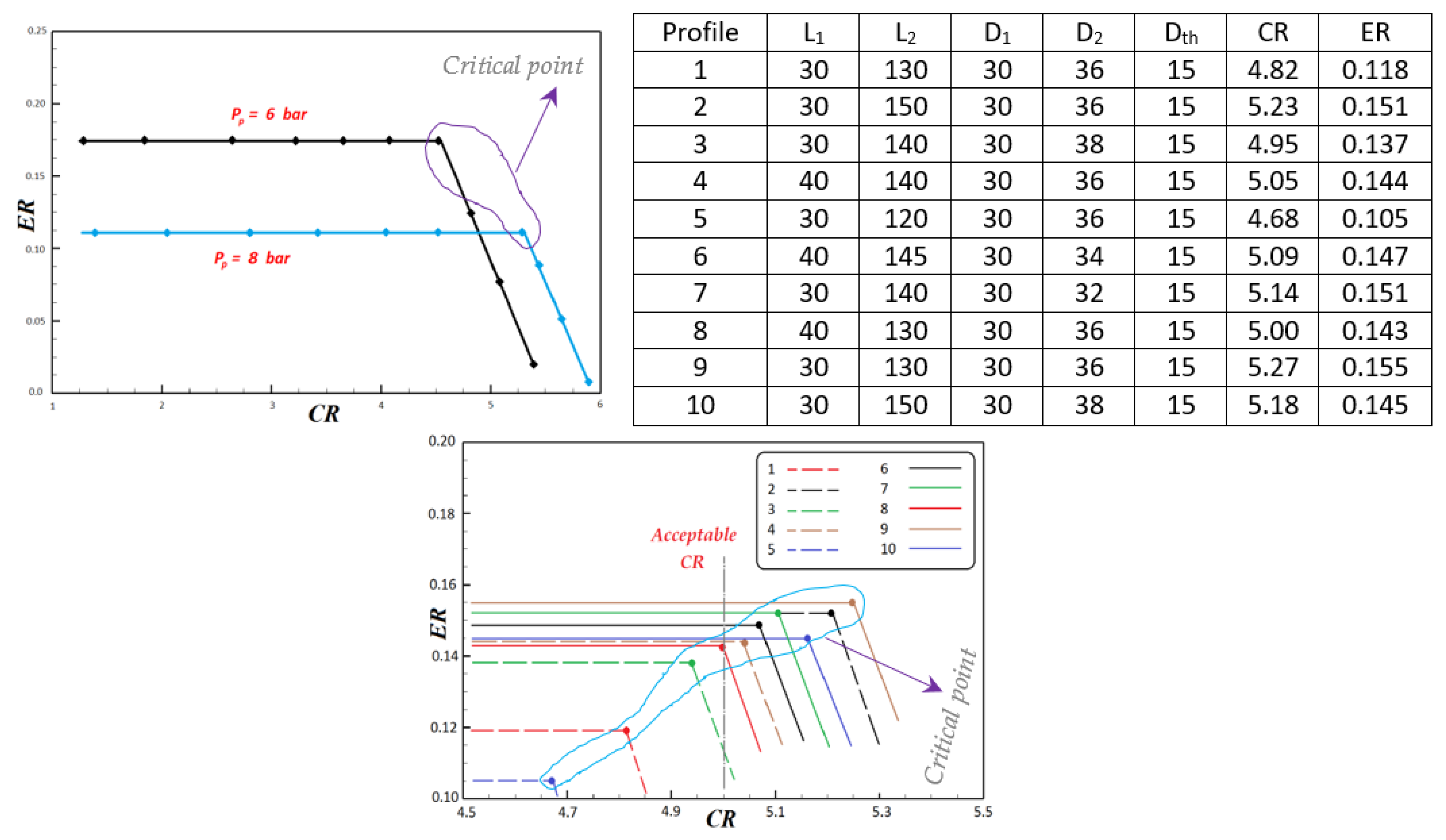
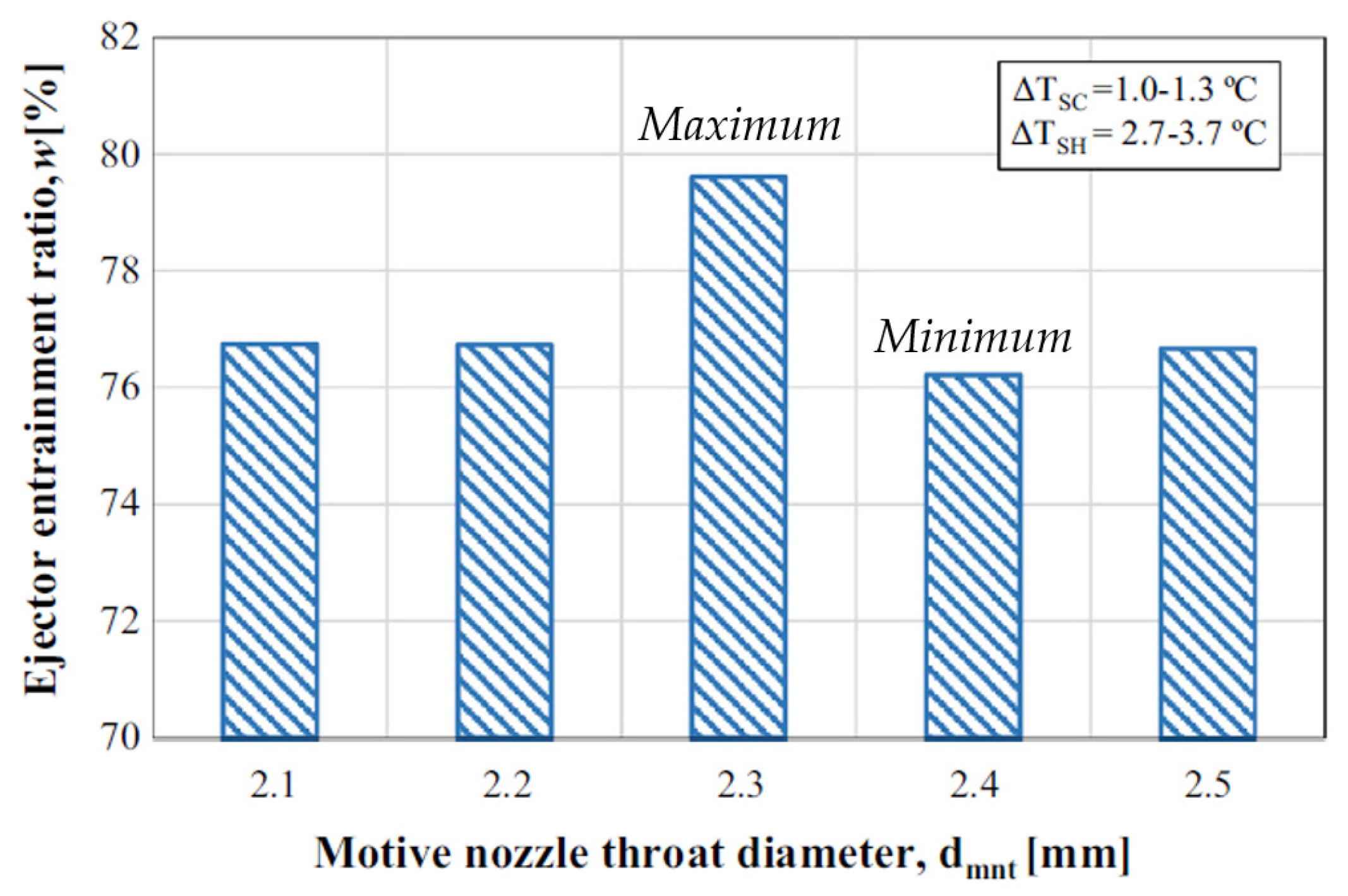
3.4. Throat Sizes
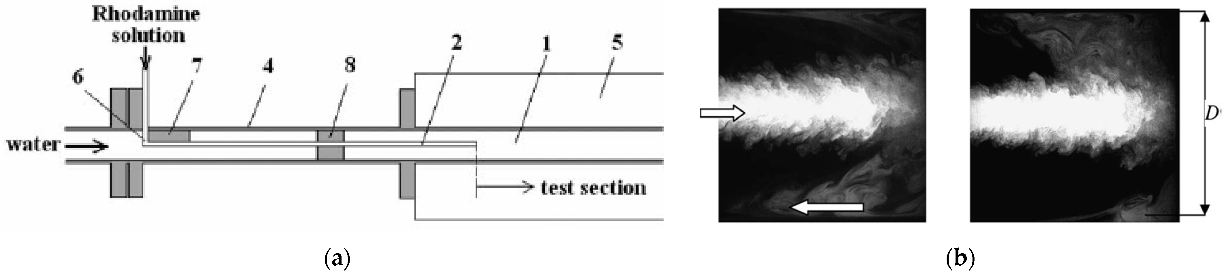
4. Flow in Ejectors
5. Operational Problems and Challenges in Ejector
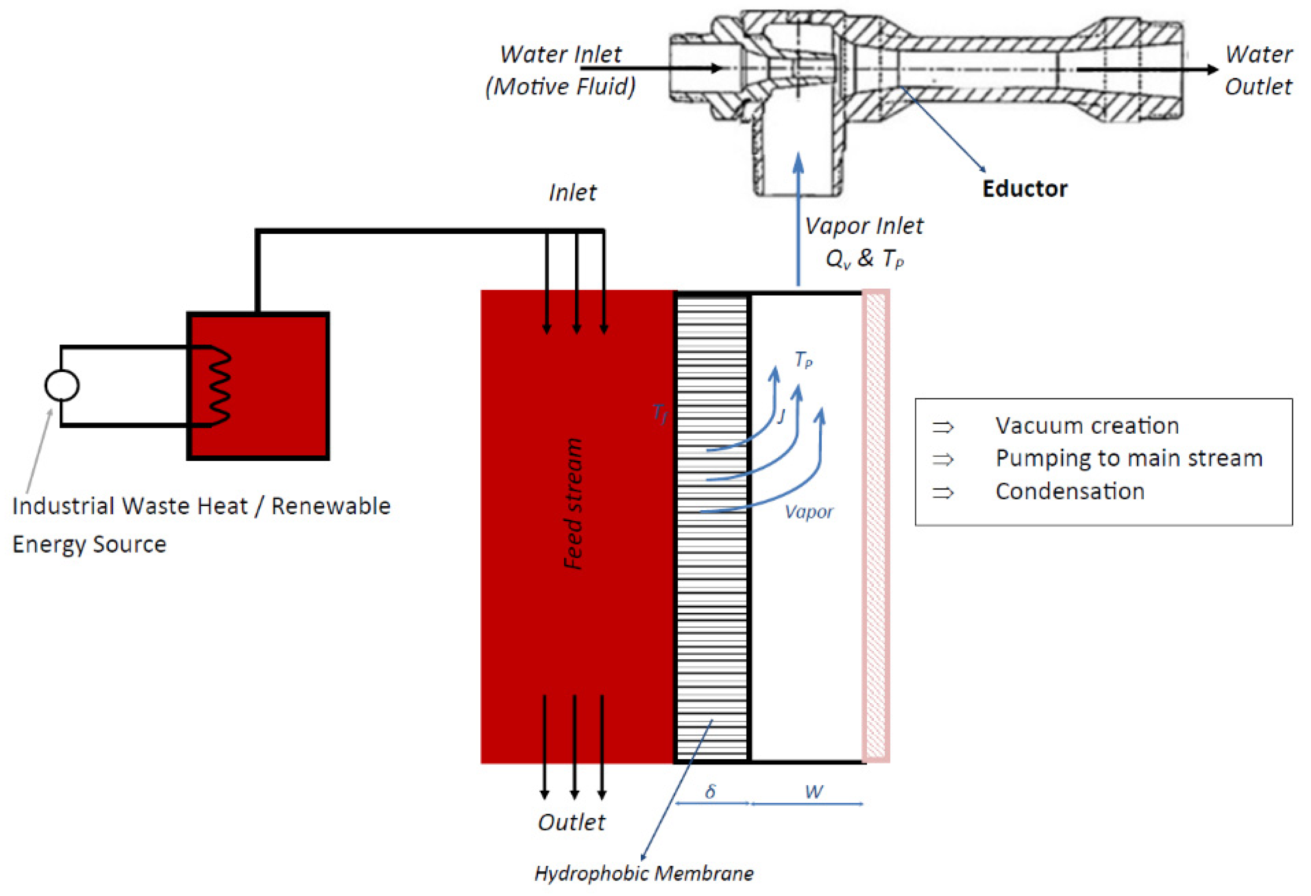
6. Ejector Based Membrane Distillation Process
7. Conclusions
- Ejectors are in successful applications for vacuum generation, secondary fluid pumping, mixing and heat and mass transfer.
- The operational characteristics were found to be dependent on geometric shape and sizes. Primary nozzle geometry and position, secondary inlet geometry and size, mixing chamber D/L ratio, length of throat and diffusing length were identified to be prime influencing factors. In addition, dynamics and property of primary flow were other associated factors.
- The operational requirement of VMD completely adheres with the outcome characteristics of ejectors. Hence integration of ejectors with VMD can result in sustainable freshwater production. Possible application in industrial wastewater treatment, could bring about significant impact. Section 5 of the work aids the viability of the system.
- Although the functionality satisfies operationality of the desalination process; the ejectors were never focused on for this specific application. Hence, design optimization is essential, for possible enhanced capacity harnessing. The following criteria are to be prioritized:
- Pressure recovery—the major drawback of the system is in pressure recovery at the outlet. Most of the energy is lost when fluid passes from high pressure to low pressure (inlet to nozzle outlet) and returns to high pressure (suction to outlet).
- Mixing enhancement—heat and mass transfer is directly proportional to the mixing index. The quality of mixing increases the effectiveness of the system. Technically, increasing the mixing layer thickness at two-phase interfaces ultimately increases it.
- Interphase shear stress—lagging and leading velocity difference at the interface absorbs energy in motive fluid due to interphase shear stress. Hence, increasing the velocity of entrained phase will increases the entrainment in the system.
- Suction enhancement—the most influential factor is suction capacity, flux, needs to be balanced with entrainment ratio, to ensure all VMD flux transfer will reach inside the ejector.
- Achievement of (iv) criterion, will support wider industrial acceptance and application. In addition, the methodology to achieve it, will further support in application-based design, analysis and manufacturing for one or multiple functionalities of the ejectors (vacuum generation, mixing or heat and mass transfer, etc.)
Author Contributions
Funding
Institutional Review Board Statement
Informed Consent Statement
Data Availability Statement
Conflicts of Interest
References
- University of Cambridge. Industrial Sustainability. 2016. Available online: https://www.ifm.eng.cam.ac.uk/research/industrial-sustainability/ (accessed on 10 July 2018).
- Battles, S.J.; Burns, E.M. United States Energy usage and efficiency: Measuring changes over time. Energy Inf. Adm. 1999. [Google Scholar]
- Rahimi, B.; Christ, A.; Regenauer-Lieb, K.; Chua, H.T. A novel process for low grade heat driven desalination. Desalination 2014, 351, 202–212. [Google Scholar] [CrossRef]
- Zhang, X.; Liu, Y.; Wen, X.; Li, C.; Hu, X. Low-grade waste heat driven desalination with an open loop heat pipe. Energy 2018, 163, 221–228. [Google Scholar] [CrossRef]
- WWAP UNESCO. The United Nations World Water Development Report 2019: Leaving No One behind; UNESCO: Paris, French, 2019. [Google Scholar]
- Haddad, C.; Perilhon, C.; Danlos, A.; François, M.-X.; Descombes, G. Some Efficient Solutions to Recover Low and Medium Waste Heat: Competitiveness of the Thermoacoustic Technology. Energy Procedia 2014, 50, 1056–1069. [Google Scholar] [CrossRef]
- Alfa Laval. How Technology Can Help Combat Water Scarcity. 2019. Available online: https://www.alfalaval.com/media/stories/municipal-wastewater-treatment/how-technology-can-help-combat-water-scarcity/ (accessed on 25 April 2019).
- Population Pyramid. Population Pyramids of the World from 1950 to 2100. 2019. Available online: https://www.populationpyramid.net/world/2019/ (accessed on 1 October 2019).
- INTERREG. Available online: https://www.interreg-central.eu/Content.Node/CE-HEAT/Low-grade-waste-heat-utilization-in-the-European-Union.html (accessed on 28 June 2017).
- Youssef, P.; Al-Dadah, R.; Mahmoud, S. Comparative Analysis of Desalination Technologies. Energy Procedia 2014, 61, 2604–2607. [Google Scholar] [CrossRef] [Green Version]
- Deshmukh, C.; Boo, V.; Karanikola, S.; Lin, A.; Straub, T.P.; Tong, D.; Warsinger, M.; Elimelech, M. Membrane distillation at the water-energy nexus: Limits, opportnities and challenges. Energy Environ. Sci. 2018, 11, 1177–1196. [Google Scholar] [CrossRef]
- Stefan, E.; Neal, L. Review of recent developments in advanced ejector technology. Int. J. Refrig. 2016, 62, 1–18. [Google Scholar]
- Takeya, Y.; Miwa, S.; Hibiki, T.; Mori, M. Application of steam injector to improved safety of light water reactors. Prog. Nucl. Energy 2015, 78, 80–100. [Google Scholar] [CrossRef]
- Chunnanond, K.; Aphornratana, S. Ejectors: Applications in refrigeration technology. Renew. Sustain. Energy Rev. 2004, 8, 129–155. [Google Scholar] [CrossRef]
- He, S.; Li, Y.; Wang, R. Progress of mathematical modeling on ejectors. Renew. Sustain. Energy Rev. 2009, 13, 1760–1780. [Google Scholar] [CrossRef]
- Sarkar, J. Ejector enhanced vapor compression refrigeration and heat pump systems—A review. Renew. Sustain. Energy Rev. 2012, 16, 6647–6659. [Google Scholar] [CrossRef]
- Besagni, G.; Mereu, R.; Inzoli, F. Ejector refrigeration: A comprehensive review. Renew. Sustain. Energy Rev. 2016, 53, 373–407. [Google Scholar] [CrossRef] [Green Version]
- Aidoun, Z.; Ameur, K.; Falsafioon, M.; Badache, M. Current advances in Ejector Modeling, Experimentation and Applications for Refrigeration and Heat Pumps. Part 1: Single-Phase Ejectors. Inventions 2019, 4, 1–73. [Google Scholar] [CrossRef] [Green Version]
- Snell, J.B. Mechanical Engineering: Raiways; Arrow Books: London, UK, 1973. [Google Scholar]
- Berkeley, F.D. Ejectors; Graham Manufactring Company Inc.: Batavia, IL, USA, 1958; Available online: https://www.graham-mfg.com/usr/pdf/TechLibVacuum/25.PDF (accessed on 1 June 2019).
- Shaozhi, Z.; Luo, J.; Wang, Q.; Chen, G. Step utilization of energy with ejector in a heat driven freeze dring system. Energy 2018, 164, 734–744. [Google Scholar]
- Macia, L.; Castilla, R.; Gámez, P.J. Simulation of ejector for vacuum generation. In Proceedings of the IOP Conference Series: Materials Science and Engineering; IOP Publishing: Bristol, UK, 2019; Volume 659, pp. 1–7. [Google Scholar]
- Kumar, R.A.; Rajesh, G. Physics of vacuum generation in zero-secondary flow ejectors. Phys. Fluids 2018, 30, 066102. [Google Scholar] [CrossRef]
- Knight, J.; Met, M. The use of steam Ejectors for the Vacuum Degassing of steel. Proc. Inst. Mech. Eng. 1966, 181, 225–241. [Google Scholar] [CrossRef]
- Kuznetsov, V.A.; Kats, Y.L. Economical vacuum degassing of steel with the use of mechanical pumps. Metallurgist 2007, 51, 220–225. [Google Scholar] [CrossRef]
- Winter, R.D.; Caldwell, J.E. Vacuum Degassing with Ejector Technology; National Forge Company: Irivne, CA, USA, 1997. [Google Scholar]
- Freedman, B.Z.; Lior, N. A Novel High-Temperature Ejector-Topping Power Cycle. J. Eng. Gas Turbines Power 1994, 116, 1–7. [Google Scholar] [CrossRef]
- Garris, C.A. Pressure Exchange Ejector. USA Patent US7497666B2, 20 September 2005. [Google Scholar]
- Oliveira, A.; Afonso, C.; Matos, J.; Riffat, S.; Nguyen, M.; Doherty, P. A combined heat and power system for buildings driven by solar energy and gas. Appl. Therm. Eng. 2002, 22, 587–593. [Google Scholar] [CrossRef]
- Zhang, C.; Lin, J.; Tan, Y. A theoretical study on a novel combined organic Rankine cycle and ejector heat pump. Energy 2019, 176, 81–90. [Google Scholar] [CrossRef]
- Zhang, K.; Chen, X.; Markides, C.N.; Yang, Y.; Shen, S. Evaluation of ejector performacne for an organic Rankine cycle combined power and cooling system. Appl. Energy 2016, 184, 404–412. [Google Scholar] [CrossRef] [Green Version]
- The Process Piping. Introduction to Priming in Pumps, The Process Piping. 2020. Available online: https://www.theprocesspiping.com/introduction-to-priming-in-pumps/ (accessed on 17 October 2020).
- Sulzer. Sulzer Ejector for Priming. 2020. Available online: https://www.sulzer.com/china/-/media/files/products/pumps-accessories/pump-and-lifiting-station-accessories/brochures/ejectorforpriming_e10514.ashx?la=en (accessed on 17 October 2020).
- Techmon. Variator Priming Ejector–VG. 2020. Available online: https://www.techmon.eu/products/varitor-priming-ejector-vg/ (accessed on 7 July 2020).
- Iron Pump. P-type Ejectors—Dimensions & Weights. 2020. Available online: https://ironpump.com/images/Products/Ejector-P-Type-Data-Sheet.pdf (accessed on 17 October 2020).
- G.A. Hanrahan Pty. Ltd. Ejector for Steam or Air Operation. 2020. Available online: http://www.hanrahanengineering.com.au/brown-ejector/ (accessed on 17 October 2020).
- Prime Tech Ejectors. Pump Priming Eductor-E-PM-3501/3502. 2020. Available online: http://primetechejectors.com/pdf/pump_priming_eductor.pdf (accessed on 17 October 2020).
- Ullah, K.R.; Saidur, R.; Ping, H.W.; Akikur, R.K.; Shuvo, N.H. A review of solar thermal refrigeration and cooling methods. Renew. Sustain. Energy Rev. 2013, 24, 499–513. [Google Scholar] [CrossRef]
- Vakiloroaya, V.; Samali, B.; Fakhar, A.; Pishghadam, K. A review of different strategies for HVAC energy saving. Energy Convers. Manag. 2014, 77, 738–754. [Google Scholar] [CrossRef]
- Fox Venturi Products, Pup Priming Ejectors, Fox Venturi Products. 2020. Available online: https://www.foxvalve.com/air-gas-steam-vacuum-ejectors/pump-priming-ejectors/ (accessed on 17 October 2020).
- SWT Water. Eductors. 2018. Available online: https://www.swtwater.com/catalog/eductors_index.htm (accessed on 7 September 2018).
- Cebeco. Products-Eductors. 2010. Available online: http://www.cebeco.com.au/products/eductors/jt-eductors (accessed on 28 July 2018).
- Schutte & Koerting. Eductors & Syphons–Water Jet Eductor. 2018. Available online: https://www.s-k.com/eductors-syphons/water-jet-eductors.cfm (accessed on 15 January 2020).
- Fox Valve, Fox Mini-Eductors. 2017. Available online: https://www.foxvalve.com/mini-eductors/introduction/ (accessed on 1 April 2021).
- Bamford & Morris Ltd. Custom Eductor Solutions for Pumping Gases. 2018. Available online: http://www.bamfordandmorris.com/eductors-for-gas.html (accessed on 15 January 2020).
- Applied Vacuum. Liquid Eductors. 2017. Available online: http://www.appliedvacuum.co.za/products/liquid-educators/ (accessed on 5 January 2020).
- Boysan, F. A Two-Fluid Model for Fluent; Flow Simulation Consultants Ltd.: Sheffield, UK, 1990. [Google Scholar]
- Oh, J.-T.; Ngoc, C.N. Development of heat pump system using thermobank and ejector for heating room and cold storage. In Electric Vehicles and the Future of Energy Efficient Transportation; IGI Global: Hershey, PA, USA, 2015; pp. 784–802. [Google Scholar]
- AB Progetti, Liquid Ejectors. 2018. Available online: http://www.abprogetti.com/liquid-ejectors.html (accessed on 25 December 2020).
- Elbel, S.; Hrnjak, P. Ejector Refrigenration: An Overview of Historical and Present Developments with an Emphasis on Air-Conditioning Applications. In Proceedings of the International Refrigeration and Air Conditioning Conference at Purdue, West Lafayette, IN, USA, 14–17 July 2008. [Google Scholar]
- Chen, X.; Somer, S.; Worall, M.; Riffat, S. Recent developments in ejector refrigeration technologies. Renew. Sustain. Energy Rev. 2013, 19, 629–651. [Google Scholar] [CrossRef]
- Eames, W. A new prescription for the design of supersonic jet-pumps: The constant rate of momentum change method. Applied Therm. Eng. 2002, 22, 71–87. [Google Scholar] [CrossRef]
- Kitrattana, B.; Aphornratana, S.; Thongtip, T.; Ruangtrakoon, N. Comparison of traditional and CRMC ejector performance used in a steam ejector refrigeration. Energy Precedia 2017, 138, 476–481. [Google Scholar] [CrossRef]
- Kumar, V.; Singhal, G.; Subbarao, P. Realization of novel constant rate of kinetic energy change (CRKEC) supersonic ejector. Energy 2018, 164, 694–706. [Google Scholar] [CrossRef]
- Ariafar, K.; Toorani, A. Effect of nozzle geometry on a model thermocompressor performance—A numerical evaluation. In Proceedings of the Annual International Conference on Mechanical Engineering, Shiraz, Iran, 16–18 May 2012. [Google Scholar]
- Zare-Behtash, H.; Gongora-Orozco, N.; Kontis, K. Effect of primary jet geometry on ejector performance: A cold-flow investigation. Int. J. Heat Fluid Flow 2011, 32, 596–607. [Google Scholar] [CrossRef] [Green Version]
- Sharifi, N.; Sharifi, M. Experimental improvement of ejector performance through numerical optimization of nozzle geometry. In Proceedings of the ASME 2013 International Mechanical Engineering Congress and Exposition, San Diego, CA, USA, 15–21 November 2013. [Google Scholar]
- Sag, N.B.; Ersoy, H.K. Experimental investigation on motive nozzle throat diameter for an ejector expasion refrigeration system. Energy Convers. Manag. 2016, 124, 1–12. [Google Scholar]
- Xue, K.; Li, K.; Chen, W.; Chong, D.; Yan, J. Numerical Investigation on the performance of different primary nozzle structures in the supersonic ejector. In Proceedings of the Eigth International Conference on Applied Energy, Beijing, China, 8–11 October 2016. [Google Scholar]
- Elhub, B.; Mat, S.; Sopian, K.; Elbreki, A.; Ruslan, M.H.; Ammar, A. Performance evaluation and parametric studies on variable nozzle ejector using R134A. Case Stud. Therm. Eng. 2018, 12, 258–270. [Google Scholar] [CrossRef]
- Seckin, C. Investigation of the effect of the primary nozzle throat diameter on the evaporator performance of an Ejector expansion refrigeration cycle. J. Therm. Eng. 2018, 4, 1939–1953. [Google Scholar] [CrossRef]
- Xu, J.; Zhozhou, C.; Chaobin, D.; Eiji, H. Study on the Performance of a Variable Geometry Ejector. In Proceedings of the 12th IEA Heat Pump Conference 2017, Rotterdam, The Netherlands, 15–18 May 2017. [Google Scholar]
- Zhang, S.; Shen, S.; Yang, Y. Numerical investigation on performance of the adjustable ejector. Int. J. Low Carbon Technol. 2010, 5, 51–56. [Google Scholar] [CrossRef]
- Kracik, J.; Dvorak, V. Preliminary study of the primary nozzle position of a supersonic air ejector with a constant-area mixing chamber. In EPJ Web of Conferences; EDP Sciences: Les Ulis, France, 2017; Volume 143, p. 2056. [Google Scholar]
- Dong, J.; Ma, H.B. Study of optimum nozzle exit position (NXP) in a steam ejector refrigeration system. In Proceedings of the 7th International Symposium on Multiphase Flow, Heat Mass Transfer and Energy Conversion, Xi’an, China, 26–30 October 2013; pp. 115–123. [Google Scholar] [CrossRef]
- Mani, K.; Tiwari, S.; Annamalai, M. Computational analysis of ejector with oscillating nozzle. In Proceedings of the International Refrigeration and Air Conditioning Conference at Purdue, West Lafayette, IN, USA, 9–12 July 2018. [Google Scholar]
- Park, S. Enhancement of entraining performance on Thermal vapor compressor for Multi-Effect Desalination Plants by Swirl Effects of Motive Steam. Numer. Heat Transf. 2009, 56, 406–421. [Google Scholar] [CrossRef]
- Yan, J.; Chong, D.; Wu, X. Effect of swirling vanes on performance of steam-water jet injector. Appl. Therm. Eng. 2010, 30, 623–630. [Google Scholar] [CrossRef]
- Banu, P.; Mallikarjuna, J.M.; Mani, A. Experimental and numerical investigation of ejector jet refrigeration system with primary stream swirl. In Proceedings of the 16th International Refrigeration and Air Conditioning Conference at Purdue, West Lafayette, IN, USA, 11–14 July 2016. [Google Scholar]
- Banu, P.; Tiwari, J.S.; Mani, A. Three-dimensional numerical investigations on ejector of vapour jet refrigeration system. In Proceedings of the Purdue Conference at Purdue, West Lafayette, IN, USA, 14–17 July 2014. [Google Scholar]
- Banu, J.P.; Mani, A. Numerical studies on ejector with swirl generator. Int. J. Therm. Sci. 2019, 137, 589–600. [Google Scholar] [CrossRef]
- Gupta, K.; Lilley, D.G.; Syred, N. Swirl Flows; Abacus Press: Tunbridge Wells, UK, 1984. [Google Scholar]
- Chlappetta, L.; Verma, P.; Radcliff, T.D. Ejector with Motive Flow Swirl. Farmington Patent US2014/0083121 A1, 10 April 2012. [Google Scholar]
- Garris, A. Pressure Exchanging Ejector and Methods to Use. USA Patent US6138456A, 31 October 2000. [Google Scholar]
- Hong, W.J.; Alhussan, K.; Zhang, H.; Garris, C.A., Jr. A novel thermally driven rotor-vane/pressure-exchange ejector refrigeration system with environmental benefits and energy efficiency. Energy 2004, 29, 2331–2345. [Google Scholar] [CrossRef]
- Hong, W.; Alhussan, K.; Garris, J.C. The supersonic/rotor-vane/pressure-exchange ejector. In Proceedings of the 39th Aerospace Sciences Meeting and Exhibit; American Institute of Aeronautics and Astronautics (AIAA): Reston, VA, USA, 2001. [Google Scholar]
- Alhussan, K.; Garris, C. Effect of Changing Throat Diameter Ratio on A Steam Supersonic Pressure Exchange Ejector. Mod. Phys. Lett. B 2005, 19, 1715–1718. [Google Scholar] [CrossRef]
- Chaiwongsa, P.; Wongwises, S. Effect of throat diameters of the ejector on the performance of the refrigeration cycle using a two-phase ejector as an expansion device. Int. J. Refrig. 2007, 30, 601–608. [Google Scholar] [CrossRef]
- Bi, R.; Hu, M.; Wang, S.; Tan, X.; Zheng, S. Effect of Throat Length on Stream Ejector Critical Back Pressure. Chem. Eng. Trans. 2017, 61, 1945–1950. [Google Scholar]
- Saini, S.; Yunus, R.; Nur, I. Effect of variations throat length on Ejector Performance. Int. J. Eng. Inf. Sci. Appl. Sci. 2018, 1, 1–6. [Google Scholar]
- Ren, Q.; Guo, X.M.; Guo, X.W.; Li, T.L. Experimental study on Performance of Two Phase Ejector Refrigeration cycle system with Two-throat Nozzle. In Proceedings of the International Refrigeration and Air Conditioning Conference at Purdue, West Lafayette, IN, USA, 14–17 July 2014. [Google Scholar]
- Wang, J.; Xie, J.; Wang, Y.-H.; Tao, L.-R. Study of vapor ejector performance on ejector throat diameter. In Proceedings of the 2011 International Conference on Materials for Renewable Energy & Environment, Shanghai, China, 20–22 May 2011; Volume 2, pp. 1779–1783. [Google Scholar]
- Khan, M.I. Effects of Nozzle Geometry on Air Flow and Temperature Distribution in an Enclosed Space. Int. J. Vent. 2007, 5, 405–415. [Google Scholar] [CrossRef]
- Wen, L.; Xiao, D. Study on Flow Field Characteristics of Nozzle Water Jet in Hydraulic cutting. In Proceedings of the IOP Conference Series: Earth and Environmental Science, Zhuhai, China, 28–30 April 2017; Volume 81. [Google Scholar]
- Kwidziński, R. Control-volume-based model of the steam-water injector flow. Arch. Thermodyn. 2010, 31, 45–59. [Google Scholar] [CrossRef]
- Di Schio, E.R.; Pulvirenti, B.; Celli, M. A New Approach for the Modelization of Water and Steam Mixing at High Pressure Conditions. Energy Procedia 2016, 101, 34–41. [Google Scholar] [CrossRef]
- Fuchs, H.; Legge, H. Flow of a water jet into vacuum. Acta Astronaut. 1979, 6, 1213–1226. [Google Scholar] [CrossRef]
- Smith, R. Steam-Water, Critical Flow in a Venturi, National Bureau of Standards; United States Department of Commerce: Boulder, CO, USA, 1971.
- Kwidziński, R. Experimental investigation of condensation wave structure in steam–water injector. Int. J. Heat Mass Transf. 2015, 91, 594–601. [Google Scholar] [CrossRef]
- Shah, I.; Chughtai, R.; Inayat, M.H. Numerical Simulation of Direct-contact Condensation from a Supersonic Steam Jet in Subcooled Water. Chin. J. Chem. Eng. 2010, 18, 577–587. [Google Scholar] [CrossRef]
- Shah, I.; Chughtai, R.; Inayat, M.H. Experimental and numerical analysis of steam jet pump. Int. J. Multiph. Flow 2011, 37, 1305–1314. [Google Scholar] [CrossRef]
- Shah, I.; Chughtai, R.; Inayat, M.H. Experimental and numerical investigation of the effect of mixing section length on direct contact condensation in steam jet pump. Int. J. Heat Mass Transf. 2014, 72, 430–439. [Google Scholar] [CrossRef]
- Yang, X.; Chong, D.; Liu, J.; Zong, X. Pressure oscillation induced by steam jet condensation in subcooled water flow in a channel. Int. J. Heat Mass Transf. 2016, 98, 426–437. [Google Scholar] [CrossRef]
- Qiu, B.; Yan, J.; Liu, J.; Chong, D.; Zhao, Q.; Wu, X. Experimental investigation on the second dominant frequency of pressure oscillation for sonic steam jet in subcooled water. Exp. Therm. Fluid Sci. 2014, 58, 131–138. [Google Scholar] [CrossRef]
- Zhdanov, V.; Kornev, N.; Hassel, E.; Chorny, A. Mixing of confined coaxial flows. Int. J. Heat Mass Transf. 2006, 49, 3942–3956. [Google Scholar] [CrossRef]
- Lines, J.; Smith, R. Ejector System Troubleshooting; Graham Corporation: Batavia, NY, USA, 1997. [Google Scholar]
- Lieberman. Troubleshooting Steam Ejectors; Digital Refining: Croydon, UK, 2014. [Google Scholar]
- Unique Systems Incorporated. Installation, Operation, Maintenance & Troubleshooting of Ejector Systems; Heat Exchange Insititute Incorporated: Towaco, NJ, USA, 2009. [Google Scholar]
- Engel, O. Some problems in the Design and Operation of Jet Ejectors. Proc. Inst. Mech. Eng. 1963, 177, 347–362. [Google Scholar]
- Jantaporn, W.; Ali, A.; Aimar, P. Specific energy requirement of direct contact membrane distillation. Chem. Eng. Res. Des. 2017, 128, 15–26. [Google Scholar] [CrossRef] [Green Version]
- González, D.; Amigo, J.; Suárez, F. Membrane distillation: Perspectives for sustainable and improved desalination. Renew. Sustain. Energy Rev. 2017, 80, 238–259. [Google Scholar] [CrossRef]
- Banat, F.; Simandl, J. Membrane distillation for dilute ethanol: Separation from aqueous streams. J. Membr. Sci. 1999, 163, 333–348. [Google Scholar] [CrossRef]
- Urtiaga, M.; Gorri, E.D.; Ruiz, G.; Ortiz, I. Parallelism and differences of pervaporation and vacuum membrane distillation in the removal of VOCs from aqueous streams. Seperation Purif. Technol. 2001, 22–23, 327–337. [Google Scholar] [CrossRef]
- Hassan, A.; Darwish, M.; Fath, H.; Abdulrahim, H. Vacuum Membrane Distillation: State of the Art. In Proceedings of the Euromed 2015 Desalination for Clean Water and Energy, Palermo, Italy, 10–14 May 2015. [Google Scholar]
- Khayet, M.; Matsuura, T. Vacuum Membrane Distillation. In Membrane Distillation; Elsevier BV: Amsterdam, The Netherlands, 2011; pp. 323–359. [Google Scholar]
- Zhang, J.; Li, J.-D.; Duke, M.; Hoang, M.; Xie, Z.; Groth, A.; Tun, C.; Gray, S. Modelling of Vacuum Membrane distillation. J. Membr. Sci. 2013, 434, 1–9. [Google Scholar] [CrossRef] [Green Version]
- Lee, J.-G.; Kim, W.-S. Numerical modeling of the vacuum membrane distillation process. Desalination 2013, 331, 46–55. [Google Scholar] [CrossRef]
- Abu-Zeid, M.A.E.-R.; Zhang, Y.; Dong, H.; Zhang, L.; Chen, H.-L.; Hou, L. A compressive review of vacuum membrane distillation technique. Desalination 2015, 356, 1–14. [Google Scholar] [CrossRef]


Publisher’s Note: MDPI stays neutral with regard to jurisdictional claims in published maps and institutional affiliations. |
© 2021 by the authors. Licensee MDPI, Basel, Switzerland. This article is an open access article distributed under the terms and conditions of the Creative Commons Attribution (CC BY) license (https://creativecommons.org/licenses/by/4.0/).
Share and Cite
Koirala, R.; Ve, Q.L.; Zhu, B.; Inthavong, K.; Date, A. A Review on Process and Practices in Operation and Design Modification of Ejectors. Fluids 2021, 6, 409. https://doi.org/10.3390/fluids6110409
Koirala R, Ve QL, Zhu B, Inthavong K, Date A. A Review on Process and Practices in Operation and Design Modification of Ejectors. Fluids. 2021; 6(11):409. https://doi.org/10.3390/fluids6110409
Chicago/Turabian StyleKoirala, Ravi, Quoc Linh Ve, Baoshan Zhu, Kiao Inthavong, and Abhijit Date. 2021. "A Review on Process and Practices in Operation and Design Modification of Ejectors" Fluids 6, no. 11: 409. https://doi.org/10.3390/fluids6110409
APA StyleKoirala, R., Ve, Q. L., Zhu, B., Inthavong, K., & Date, A. (2021). A Review on Process and Practices in Operation and Design Modification of Ejectors. Fluids, 6(11), 409. https://doi.org/10.3390/fluids6110409