Review

A Review on Process and Practices in Operation and Design Modification of Ejectors

1
Department of Aerospace, Mechanical and Manufacturing Engineering, RMIT University, P.O. Box 2476, Melbourne, VIC 3001, Australia
2
Faculty of Engineering and Food Technology, Hue University of Agriculture and Forestry, Thành phố Huế 530000, Vietnam
3
State Key Laboratory of Hydroscience and Engineering, Department of Energy and Power Engineering, Tsinghua University, Beijing 100084, China
*
Author to whom correspondence should be addressed.
Fluids 2021, 6(11), 409; https://doi.org/10.3390/fluids6110409
Submission received: 21 July 2021 / Revised: 8 August 2021 / Accepted: 9 August 2021 / Published: 11 November 2021
(This article belongs to the Special Issue Multiphase Flow in Pipes with and without Porous Media)

Abstract

:
This work reviews the current operational condition and activities on design modification for different applications of ejectors. Ejectors being a simple mechanical system capable of performing multiple fluid related functions (vacuum generation, pumping, mixing, condensing and heat exchanging), have been an essential part of several industrial processes. Two areas have been emphasized; internal flow and application-based modifications in components of ejectors. The geometry and inlet flow conditions were found to be the prime influencing factor of its performance. The objective and application-based modifications were performed on the primary nozzle, secondary nozzle, mixing chamber, throat and diffuser. The resultant performance was found to be dependent on operational condition and fluid type. This emphasizes the requirement of application-based design selection of the technology. In addition, the flow dynamics of condensing, non-condensing, particle and slurry flow has been studied based on available literatures. The one-point final objective is to identify the usability of primary water jet ejectors for active vapor transport and condensation, to replace vacuum pump and condenser in compact domestic water desalination system.

1. Introduction

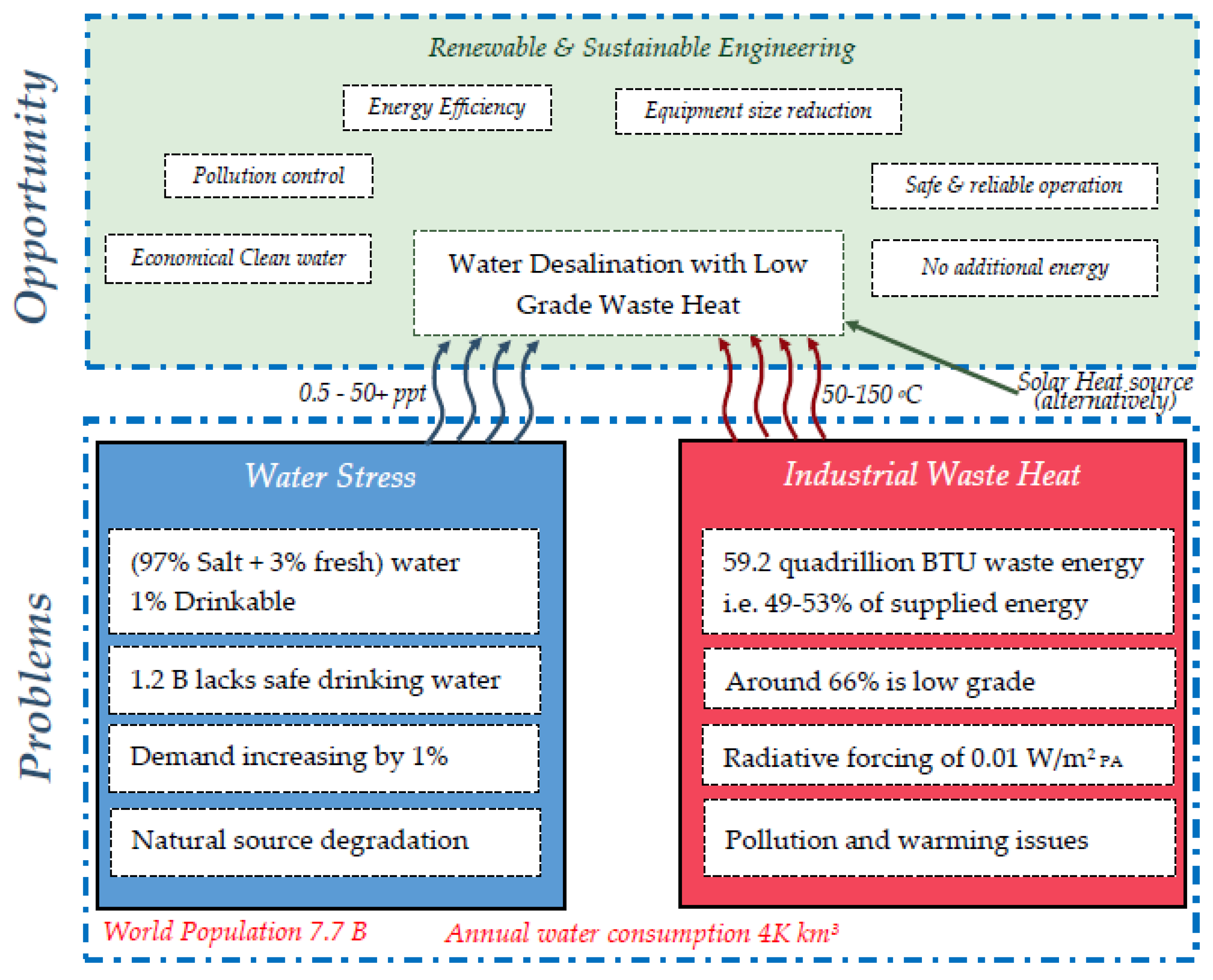
Modern day technology focuses on the improvement of process or product, from a sustainability perspective, to have persistent present enrichment, for the future. Sustainable engineering designs system and process, which uses energy and resources with positive assurance towards environment, economic and social challenge [1]. The energy efficiency concept on sustainability focuses on: more work being done with the same amount of used energy and the same work being done with lower amount of used energy [2]. Water stress and waste heat recovery are two separate global concerns. There has been a global initiative on complementing each other to reach a common economic and sustainable solution [3,4]. Figure 1 describes the severity of the concerns and solution by utilizing waste heat for desalination. Thus, the developed system has positive assurance on environmental impact, energy efficiency and economical water production prospects. This is a technology-based review on the technical capability and extent of ejectors for developing ejector-based water desalination systems using low grade (industrial waste/solar) heat sources.
Ejectors operate by the conversion of pressure energy in motive fluid (water) to velocity energy, which creates a low-pressure zone for suction of target fluid (water vapor). The prime objective of this study is to make a collective summary of progress on design criterion and its optimization associated with ejectors. Membrane distillation being a promising technology for water desalination using low grade heat sources, system integration for simple, economical, better and reliable technology has been sketched. The capability of ejectors integrated with membrane distillation processes address waste heat recovery and water supply with possible extended application in wastewater treatment [10,11].
Ejectors being a well-accepted existing technology, application-based timely study has been performed on it along with collective summary on research updates. Elbel et al. [12] reviewed advances in application technologies of ejectors and associated cycles, Takeya et al. [13] studied application of steam injectors for enhancement of safety of a water reactor and its performance status, Chunnanond et al. [14] focused on applications of ejectors in refrigeration technology, He et al. [15] summarized the progress of mathematical modelling on ejectors, Sarkar et al. [16] prioritized vapor compression and heat pump systems with ejectors and Besagni et al. [17] investigated ejector refrigeration systems; these are some of the associated reviews on application and modelling. Aidoun et al. [18] reviewed modelling, experiments and applications of single-phase ejectors for refrigeration and heat pumps. The existing literature indicates that summary of research attempts on design modification is lacking. Hence this work summarizes the existing practices implemented for design modification or performance optimization for relevant industrial applications.

2. Ejectors

Primarily, this mechanical concept was derived for steam injection, which was invented by Henri Giffard in 1858 and patented by Messrs Sharp Stewart & Co. of Glasgow, in the United Kingdom [19]. Ejectors have varying designs with various sizes, based on their application and fluid used. Despite having lower efficiency; low cost, self-priming, absence of moving parts, safety, versatility, motive-based control, easy installation, dual operation and no operation and maintenance costs makes it one of the most suitable technologies in numerous industrial applications.

2.1. Construction

A general ejector is constituted of the inlet pipe, nozzle, suction chamber, mixing chamber, throat and diffuser (Figure 2). Motive and suction fluid of the same or different phases flow through the inlet and suction port, mix in the mixing chamber, accelerate through the nozzle and recover pressure in the diffuser. Primary nozzles are usually of converging/diverging type (based on application). Carbon steel, stainless steel, brass, titanium, PTFE, carbon, poly propylene, UPVC, AB and Hastelloy are common materials used for their construction [20].

2.2. Applications

Operationally, ejectors can be single phase or multiphase systems with compressible or incompressible flow functioning as pump, compressor, heat exchanger, vacuum pump or condenser. Depending on the application, the primary fluid can be liquid, or gas and the secondary fluid can be liquid, gas or particles. Broadly, they are categorized as liquid–liquid, liquid–gas, gas–liquid, gas–gas, liquid–particle and gas–particles ejectors. The application and function of ejectors in several processes has been highlighted below:

2.2.1. Vacuum Pumping and Degassing

The fact of installation flexibility and efficient operation supports ejectors as a suitable alternative for vacuum generation. They are used in vacuum packing, drying, evaporation, gas ejection, etc. processes in industries. [21] There is zero secondary flow, while using ejectors as a vacuum pump. Macia et al. explains the influence of zero secondary flow on unsteady phenomenon in vacuum ejectors. [22] The physics of vacuum generation and formation of recirculation bubbles on circumference of jets has been visually explained by Kumar et al. [23]. In steel industries, larger rejection due to voids and strength led to adaptation of ejector-aided vacuum cooling. After placing of the ladle/mold in the cooling chamber, degassing is performed, which ejects hydrogen, oxygen, nitrogen and other dissolved gases trapped within the mold, ensuring cleanliness, ductility and toughness of the steel. This vacuum is increased at different steps by regulating motive flow [24,25]. A case study from National Forge Company, PA, recommended vacuum degassing through ejector, as an essential step in producing high quality steel. The installed system was not able to meet the vacuum requirement after being in operation for thirty-six years, pumping hot and dirty gases from steel at a temperature of around 3000 °F. The new system was developed with SS 303 material and ensured periodic cleaning of scales [26].

2.2.2. Power Cycle

Although the operational limit of gas turbines is 1200 °C, cost, life and ash deposition limit the maximum steam temperature to 560 °C. The physical structure allows high temperature operation for better efficiency of Rankine cycle but the high steam pressure and resultant dynamic effect on blades limits the range. A topping cycle allows operation of high temperature boilers at low pressures by using very low vapor pressure top fluid, but they require high temperature turbines. [27] With an ejector-based topping cycle, they compress secondary gas which prevents loss of exergy through secondary work [28]. Oliveira et al. [29] developed a combined power generation and cooling cycle in ejector-based Rankine cycles. A part of turbine power output was utilized in running ejector-based cooling systems. The performance of these combined systems was also evaluated by Zhang et al. and Zhang et al. [30,31].

2.2.3. Other Applications

Desalination: is the major application objective of this work. The prospective application of ejectors in desalination systems for combined vacuum pumping and condensation with active vapor transport has been examined in the later section.
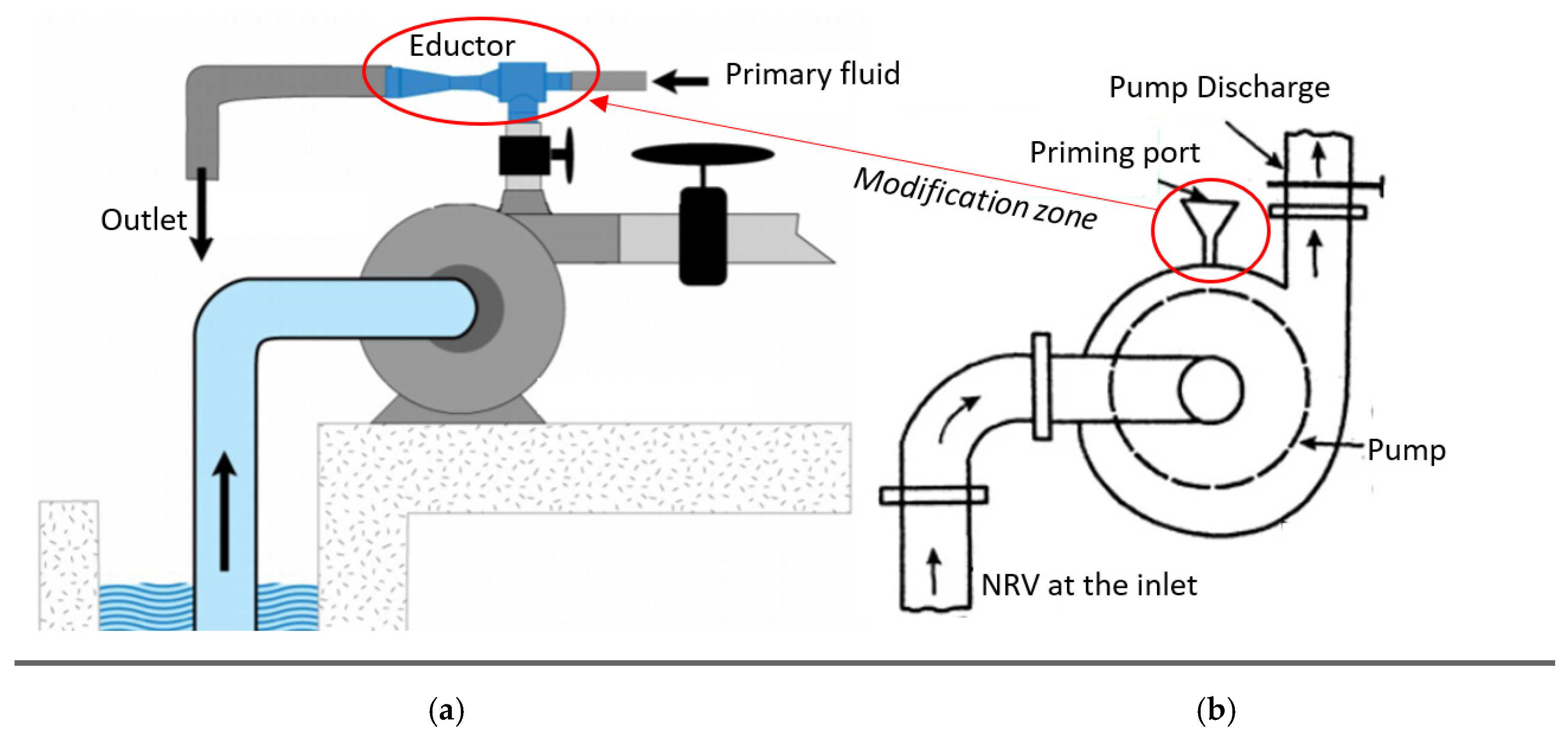
Pump priming: This is essential to minimize start-up damage on the impeller by reducing the gas boundary. Ejectors have been a compulsory part for priming of self-non-priming industrial centrifugal pumps [32]. Liquid/compressed air as motive fluid creates a vacuum inside the suction line of the pump, which draws the liquid to submerse the impeller (Figure 3). Vacuum pumps either require liquid supply or limit liquid injection during dry operation, hence ejectors stand out as superior (compared to vacuum pump, priming tank and foot valves). They were found to be installed in any orientation and recorded to be effective in priming up to 8 m suction head with primary fluid pressure of 4–10 bar [33]. The flexibility on adjustment of vacuum level and priming speed though primary flow and simple construction and installation makes it more favorable [34,35,36,37].
Refrigeration: The requirement of low capital and operational cost, low energy and simplicity has suggested ejector refrigeration systems as a strong alternative to mechanical compressor-based systems [38,39]. Details on the application in refrigeration technology has been reviewed by several reviewers in the past [14,17].
Figure 3. (a) Ejector priming, (b) manual priming (source [40]).
Fluids 06 00409 g003
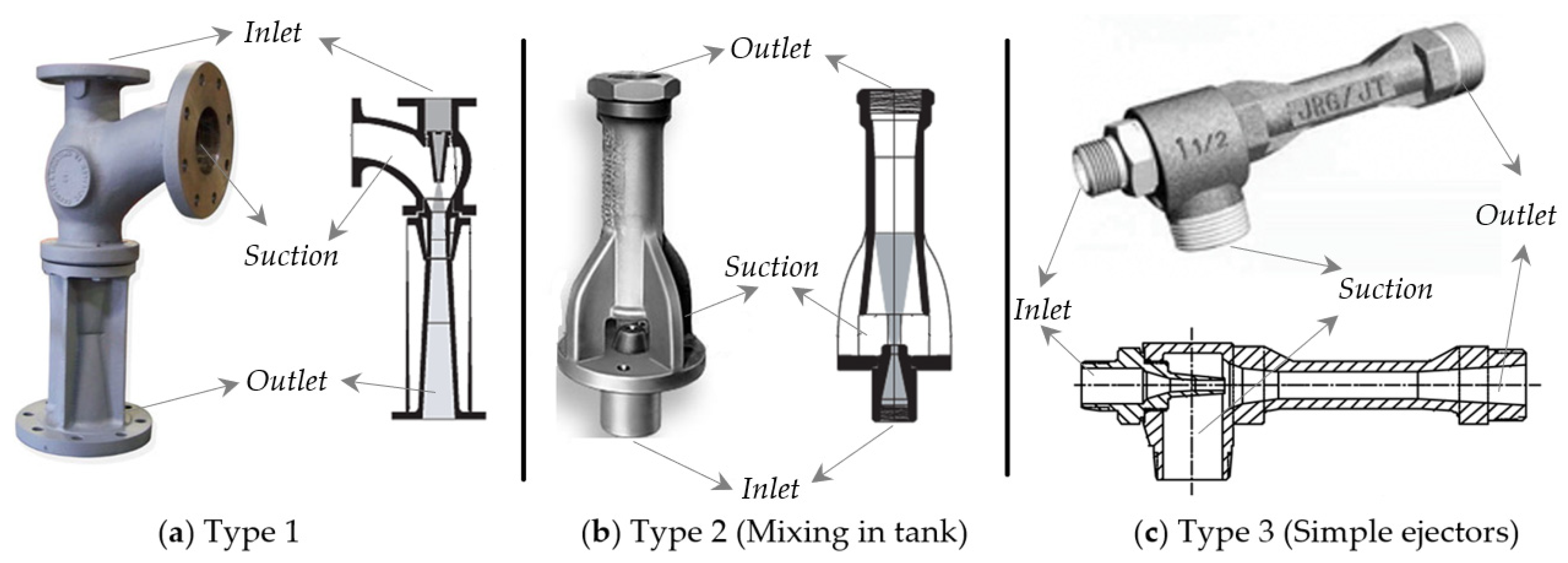
Based on the application in the industrial technologies various ejectors are available in the market. The construction and shapes of ejectors are shown in Figure 4.

2.3. Operational Principle

In the case of ejectors, the jet passing nozzle induces steady flow eddy current to its surroundings, at the suction chamber, due to momentum transfer, which accelerates the secondary flow. During this momentum exchange of primary fluid into secondary, the secondary phase forms dispersed bubbles inside the primary flow stream. This momentum exchange is defined by the momentum exchange coefficient which is a function of drag coefficient, bubble size and phase velocities [47]. The potential energy in two phases is converted to kinetic energy through a special case of Bernoulli—Venturi effect, where flow mixes and accelerates through the mixing chamber. The two-phase mixing results in the induction of pressure shock waves of high frequencies. The accelerated flow with dropped static pressure passes through the throat; this causes further movement of the secondary phase from the suction port into the motive stream. At the diffuser section, velocity decreases and hence the fluid recovers pressure energy and compress the secondary phase before discharge. Thus far, the system has been able to recover only about 40% of pressure energy. Here, the system is performing three operations at once, causing suction of low-pressure fluid, mixing it with mainstream and discharging at a higher pressure. The discharge occurs at an intermediate of motive and suction pressure [48,49].
The static pressure difference in the two-phase flow through a narrow constriction, may result in fan out of primary flow core and form a fictive throat, where flow continues after the secondary flow attains sonic condition. Although not practiced, but concepts on the use of additional suction nozzle for pre-acceleration of stagnant suction fluid has been discussed to reduce large shearing loss during mixing of phases at the high-velocity difference. It can also be a supporting factor to minimize the fan out phenomenon. Performance characteristics of ejectors are defined through suction pressure ratio and mass entrainment ratio. The ratio of system exits to suction flow pressure is suction pressure ratio and the ratio of suction to motive mass flow rate is entrainment ratio. A system is said to be well designed if it has large suction pressure and mass entrainment ratios at the same time [50].

2.4. Performance Estimation Parameters

For almost all applications, performance is measured through entrainment ratio (ER) and compression ratio (CR). Compression ratio is the fraction of delivery pressure to suction pressure and entrainment ratio is a fraction of suction mass to motive mass flow rate, numerically defined by equations.
E R = m ˙ s m ˙ m
C R = P d P s
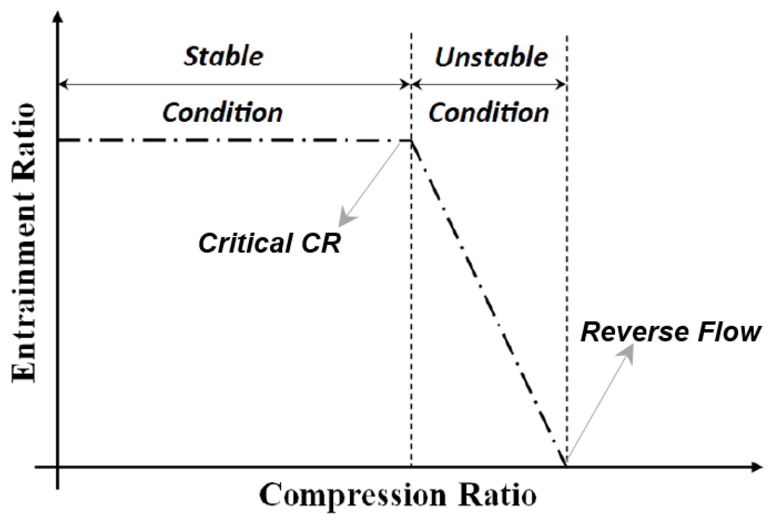
Calculated values of ER for each of the cases of CR are plotted for Figure 5, which forms performance characteristics for the ejector. There are two operational conditions, stable and unstable. With momentum induction of motive flow, secondary flow continuously entrains, resulting in declination of secondary flow pressure, this causes a gradual increment in CR of the ejector. Figure 4 describes three prime operation modes, stable, critical and unstable. At stable, the entrainment ratio remains unchanged until its critical CR is reached. At critical CR, the highest suction occurs, hence it is called maximum discharge point (MDP). Post this, fluctuation and drop in entrainment ratio were observed along with reversed flow. Reversed flow condition is the minimum ER above which motive flow reverses in the loop. Practically, the performance curve is drawn by varying back pressure, at constant inlet pressure and temperature [51].
Experimental methods with implementation of pressure and flow sensors or orifices have been used to log the result for performance estimation. Computational methods with pressures as boundary conditions were found to be abundantly implemented, along with an additional definition of condensation model in some of the cases.

3. Design Modifications of Ejector

Ejectors are broadly of two types based on geometric construction, constant area mixing (CAM) and constant pressure mixing (CPM). Eames [52] proposed a new design with constant rate of momentum change, which has the advantage of both CAM and CPM. Computational and experimental studies show better overall performance of ejectors [53] with increases in critical condensing temperatures and higher entrainment ratios. Kumar et al. [54] considered the rate of energy change as a primary consideration for ejector design. The constant rate of kinetic energy change method allows overcoming the thermodynamic shock by shifting to a description of flow physics.

3.1. Nozzle

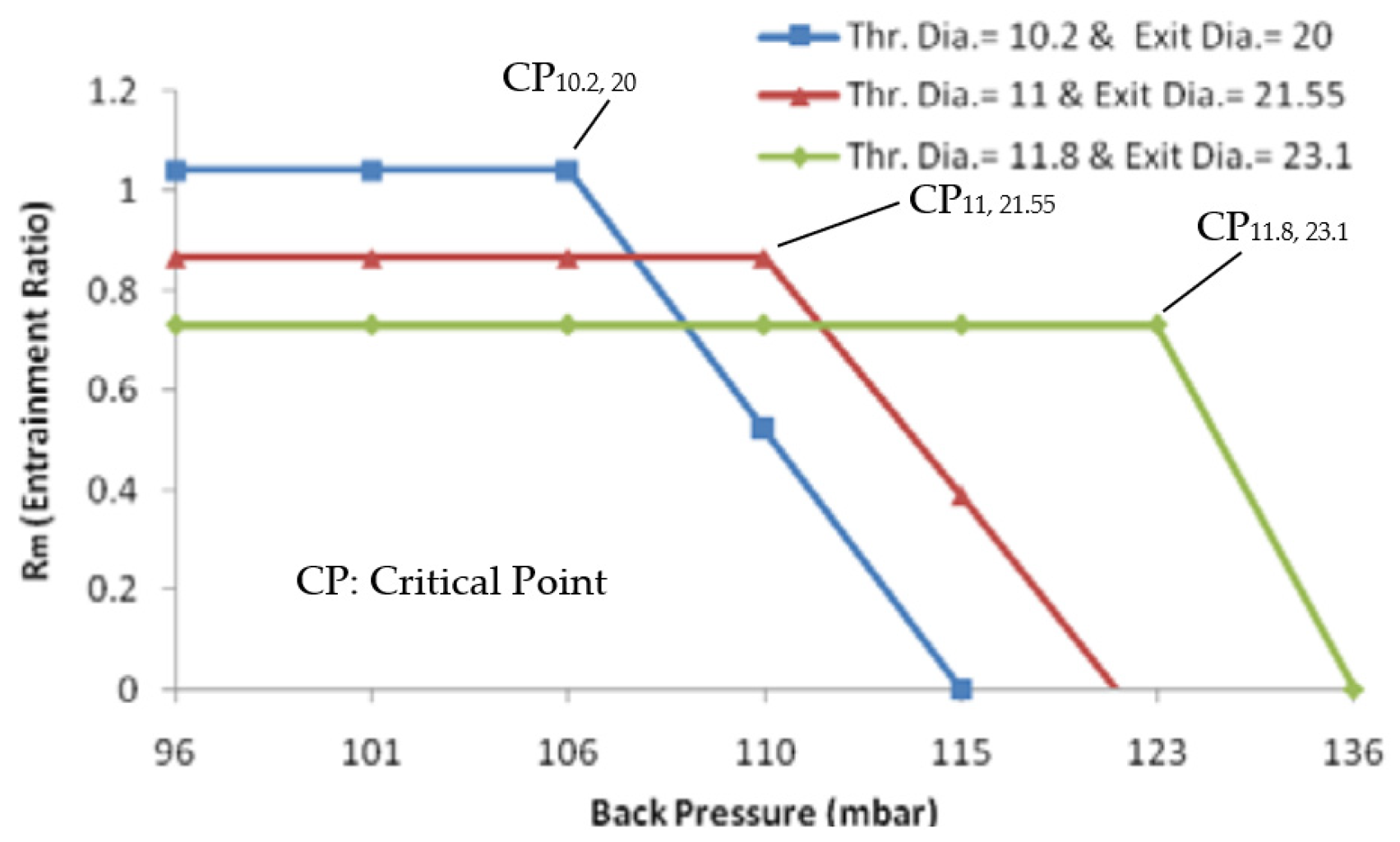
Ariafar et al. [55] numerically studied the effect of three different nozzle geometries (throat diameter ranging from 10.2 to 12 mm) on the performance of the thermo compressor, using water vapor as motive fluid with pressure ranging from 1.25 to 1.75 bar. With larger nozzle diameter, higher mass flow rate occurs resulting in higher momentum and kinetic energy hence it results in the formation of high critical back pressure at the system outlet. This in turn has been found to decrease the entrainment ratio (Figure 6).
Behtash et al. [56] discussed the effect of different primary flow geometries (two circular nozzles of diameter 15 and 30 mm, two elliptical nozzles with minor and major axis ratios of 0.4 and 0.6 with b = 30 mm, a square nozzle with length 30 mm and two exits) on the interaction of diffracted shock wave patterns and resulting vortex loop emissions.
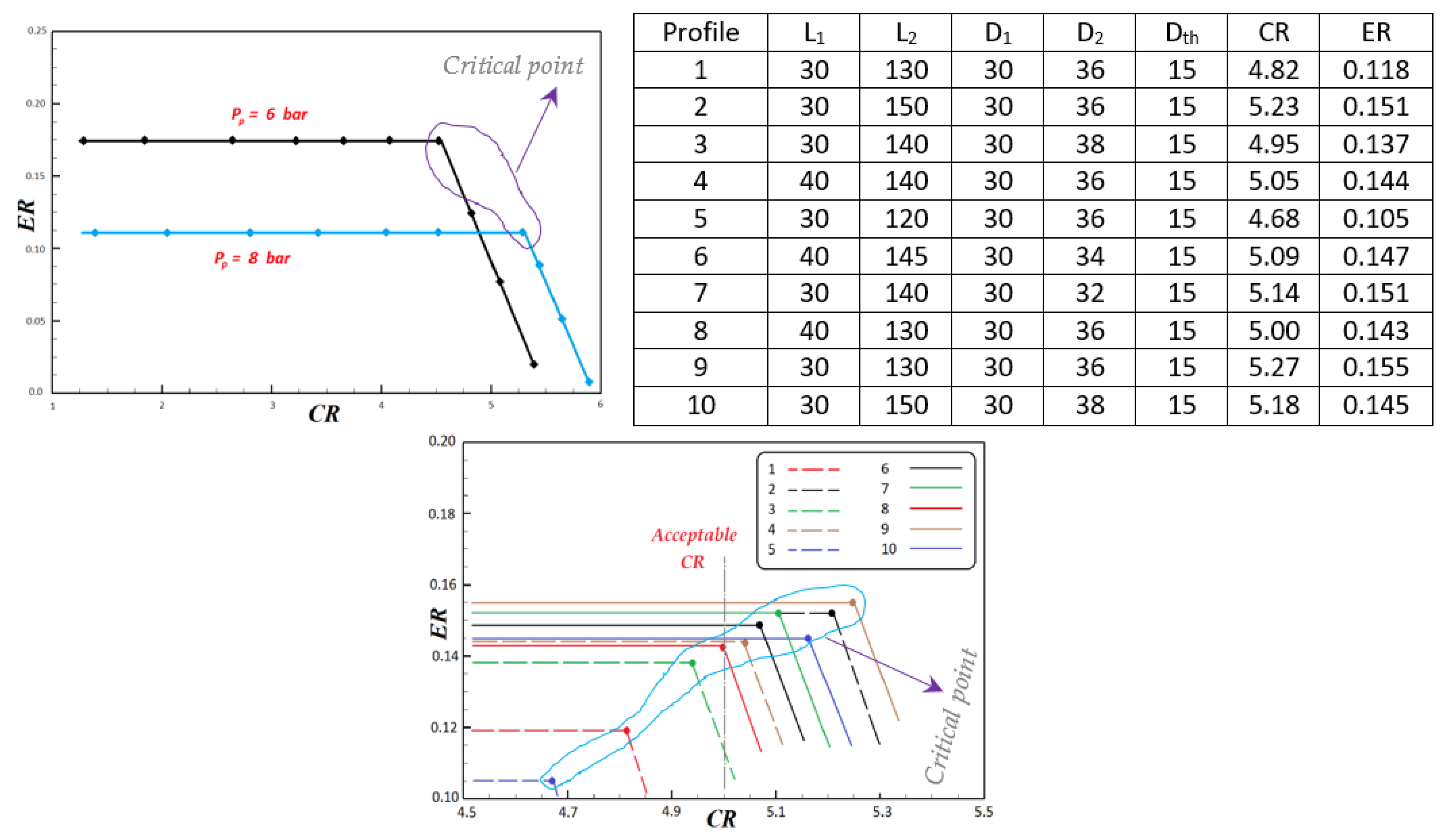
Sharifi et al. [57] numerically optimized and verified the performance of a malfunctioning steam jet ejector, for its compression ratio, as the designed primary pressure was 6 bar while its operational requirement of vacuum was achieved when raised to 8 bar. Focusing its application for the MED desalination process for maintaining low pressure inside the evaporator, the study was performed on ten different nozzle geometries for highest entrainment at constant boundary condition. Figure 7 is the result of numerical simulation for the designed pressure of 6 bar and operating pressure of 8 bar. Compared to operating pressure, the designed pressure condition has higher entrainment ratio as the motive mass flow through choked nozzle is higher, while maximum discharge point (MDP) is higher with operating pressure because of larger compression ratio caused by high energy motive steam at high pressure entering the system. Optimization may be affected by several methods but one of the important factors is improving geometries. For technical and financial feasibility, with a goal of attaining desired vacuum level at suction chamber at nominal operating condition of 6 bar, optimization was performed. A nozzle has major dimension parameters, namely, converging and diverging length, inlet, outlet and throat diameters. Higher ER refers to higher suction flow, the 9th profile in the observation shows the highest ER of 0.155 with CR of 5.27.
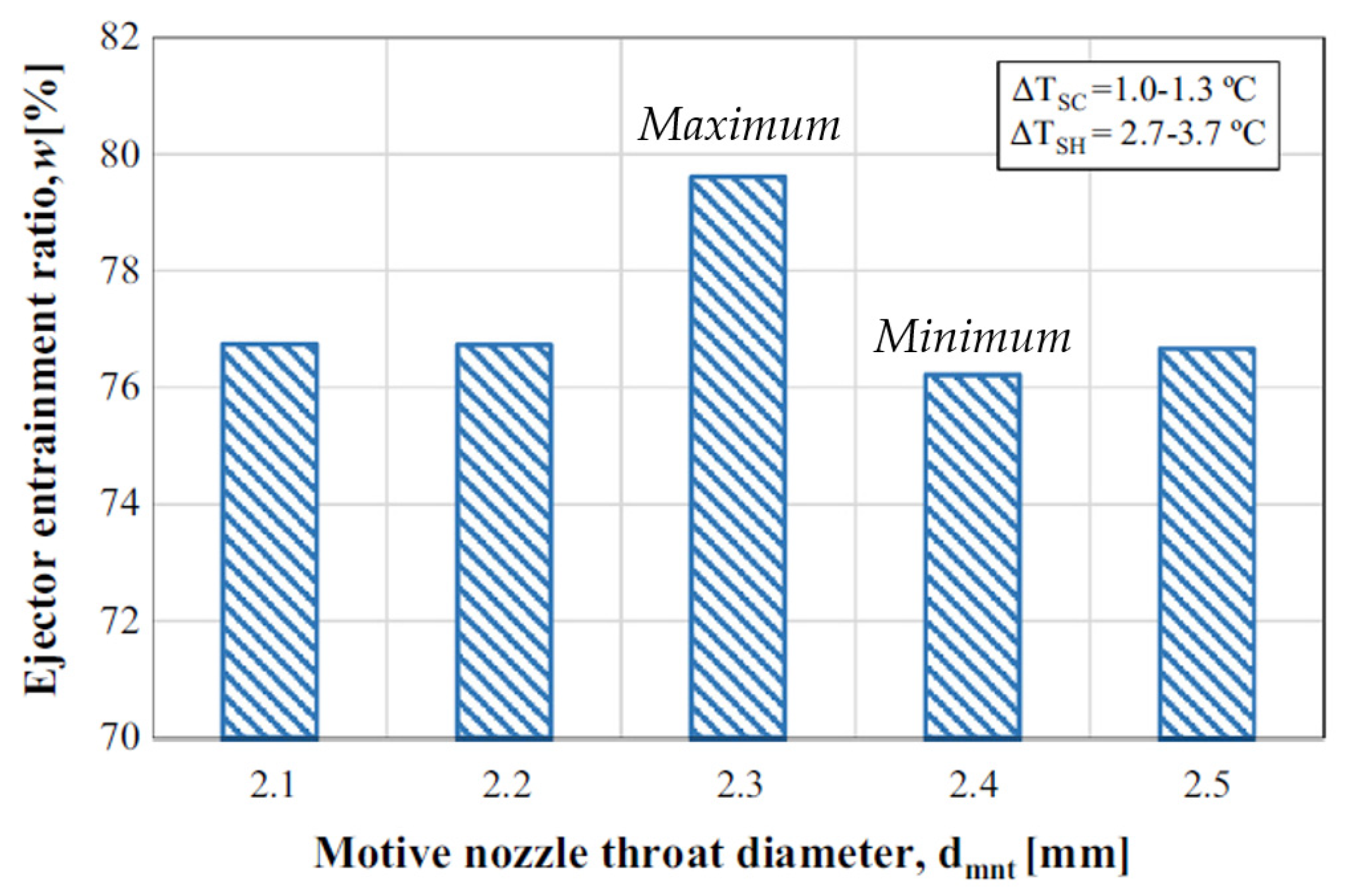
Sag et al. [58] experimentally studied the effect of throat diameter and position of primary nozzle on performance of the vapor compression system, with design and manufacturing of ejectors based on established mathematical relations. The system operates on motive fluid such as R134a, causing entrains from the evaporator. Primary nozzles have diameters of 12 mm and angles of 36°, with primary nozzle throat diameters of 2.1, 2.2, 2.4 and 2.5 mm, having constant section throat and mixing chamber of 9 mm. Figure 8 shows entrainment ratios at different motive nozzle throat diameters; at 2.3 mm, the maximum entrainment ratio was observed since the ratio of missing chamber cross-section to cross-sectional area of nozzle throat is optimum. The variation of around 4% with geometry was observed.
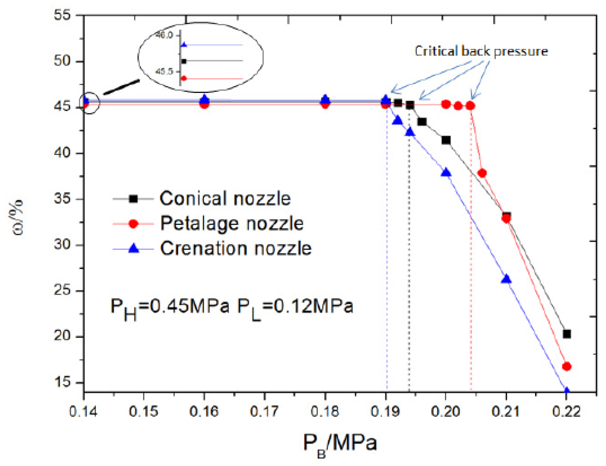
Xue et al. [59] used a computational method to study the effect of three nozzles (conical, petalage and crenation nozzles) on performance of supersonic ejectors. Except for outlet shape, all other parameters are kept constant (area ratio, area of throat of mixing chamber to nozzle throat = 3.24, primary throat diameter = 10 mm, length of ejector’s throat is 6 times its diameter; 18 mm, with constant, exiting area). The study focused on critical, sub-critical and back flow operational modes where both back pressure and entrainment ratio were examined to explore the highest back pressure and entrainment ratios. Figure 9 is the plot for entrainment ratio versus back pressure, computed from the numerical study; at initial conditions, entrainment ratio is higher for crenation while at critical back pressure, petalage has highest entrainment as well as back pressure.
Elhub et al. [60] studied the optimum position of nozzle exit for cooling cycle in R134a refrigeration systems, through computational method. An extended work is presented with a provision for a movable ejector at varying distance from 2 to 8 mm, to accommodate varying operational requirements and conditions. At low distance, improper mixing between primary and secondary flow resulted in low entrainment, while at higher distance, outlet pressure is found to be more dominant in causing back pressure, hence 3 mm is the optimum distance at which entrainment ratio of about 0.7 was achieved.
Seckin [61] used an empirical method to study the effect of constant pressure two-phase ejector primary nozzle throat diameter, on the ejector expansion refrigeration cycle using R134a as the refrigerant. At condenser temperatures of 50, 60 and 70 °C and evaporator temperatures of 0 °C, nozzle throat diameter, condenser temperature and entrainment ratio are affected. With increasing temperature of condenser, larger diameter nozzles are required.
Xu et al. [62] performed experimental investigation on supersonic (converging-diverging with throat diameter of 1.3 mm and exist diameter of 1.36 mm) and subsonic (converging with throat diameter of 1.3 mm) nozzle with variable geometry ejector to utilize unstable solar heat as driving energy for stable refrigeration systems. The diameter and length of mixing sections are 2.08 and 10.0 mm, respectively. Driving and suction flow are induced through generator and evaporator, respectively, using R134a as working fluid. Variable geometry ejectors were found to have achieved better performance in varying operating conditions and supersonic nozzles were found to demonstrate better performance compared to subsonic nozzles. Figure 10 shows the performance of ejectors for varying nozzle openings for two different nozzle geometries, where optimum point for best performance was observed, which decreases on both sides.

3.2. Primary Nozzle Position

Conventional ejectors are designed to operate at a single optimum point; in practice operation may vary from it, which results in performance deterioration. Nozzle optimum position is to be set such that no secondary flow occurs.
In the mixing section, motive and suction fluid mixes in the phenomena of heat and mass transfer, during pressure recovery of this flow shock waves are induced in the diffuser. Zhang et al. [63] computationally studied the effect of varying primary nozzle openings on ejector operation. Pressure of 300 kPa, 80 kPa and 220 kPa were selected for motive inlet, suction and outlet, with water vapor as motive fluid. Results based on turbulence models k-e standard, k-e RNG and k-e RSM, were compared with experiments and were compared with experimental conditions. Performance deterioration with exceeding discharge pressure beyond critical pressure was observed, where computational results with k-e RSM, were in better agreement with experiments. A difference in entrainment ratio of 0.1 was observed, which is around a 47% improvement.
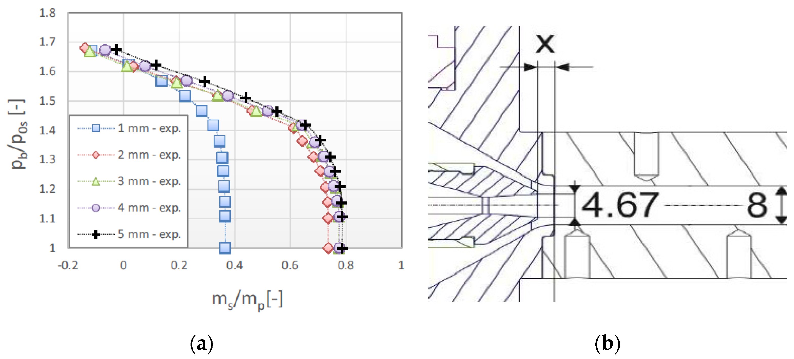
Kracik et al. [64] investigated the effect of primary nozzle axial position with air as working fluid maintaining Mach number of 2.06 at the primary nozzle exit (Figure 11). Two-dimensional axisymmetric computational study and experimental validation of results were performed for each of the cases with nozzle distance from 1 to 5 mm at unit interval. Deviations were observed in off-design regions, with the possibility of inclusion of simple computational model. At 1 mm the performance is distinct while in other spacing they seem to be almost similar, with maximum entrainment of 0.78.
Dong et al. [65] used movable primary nozzles of three kinds and diffusers of two kinds for identifying its optimum position and design, respectively, experimentally in the refrigeration cycle (described in Figure 12). Variation in optimum operational position was observed in all the cases with better coefficient of performance for nozzle 1, location of position optimum position is dependent on the kind of nozzle being used and it is independent of the type of diffuser being used.
Mani et al. [66] used UDF function to define oscillation between two points, for computational analysis of oscillating primary nozzle. Figure 13a,b is the velocity contour plot for oscillation at 5 Hz frequency at 2° and 10° angles, with inlet, suction and outlet pressure boundary conditions as 4.5 bar, 1 bar and 1 bar respectively. It shows that velocity waves transport along with the axial plane of the system. Figure 13c is the plot for varying frequency at different oscillation angles. In observed cases, ER is lower compared to the steady result, but comparing absolute oscillating ranges, it shows improvement in results with increasing oscillation angle; R&D can focus on discovering a suitable combination of amplitude and frequency to enhances performance. There are challenges in integration of actuator for consistency in oscillation in the technology.

3.3. Inlet Swirling Vanes

Performance of the ejector system can be enhanced by proper mixing of motive and suction flow. Improvement in entrainment ratio by inducing swirl in primary flow has been studied [67], it has been highlighted to have increased contact time between primary and secondary flow with increased shear force effect.
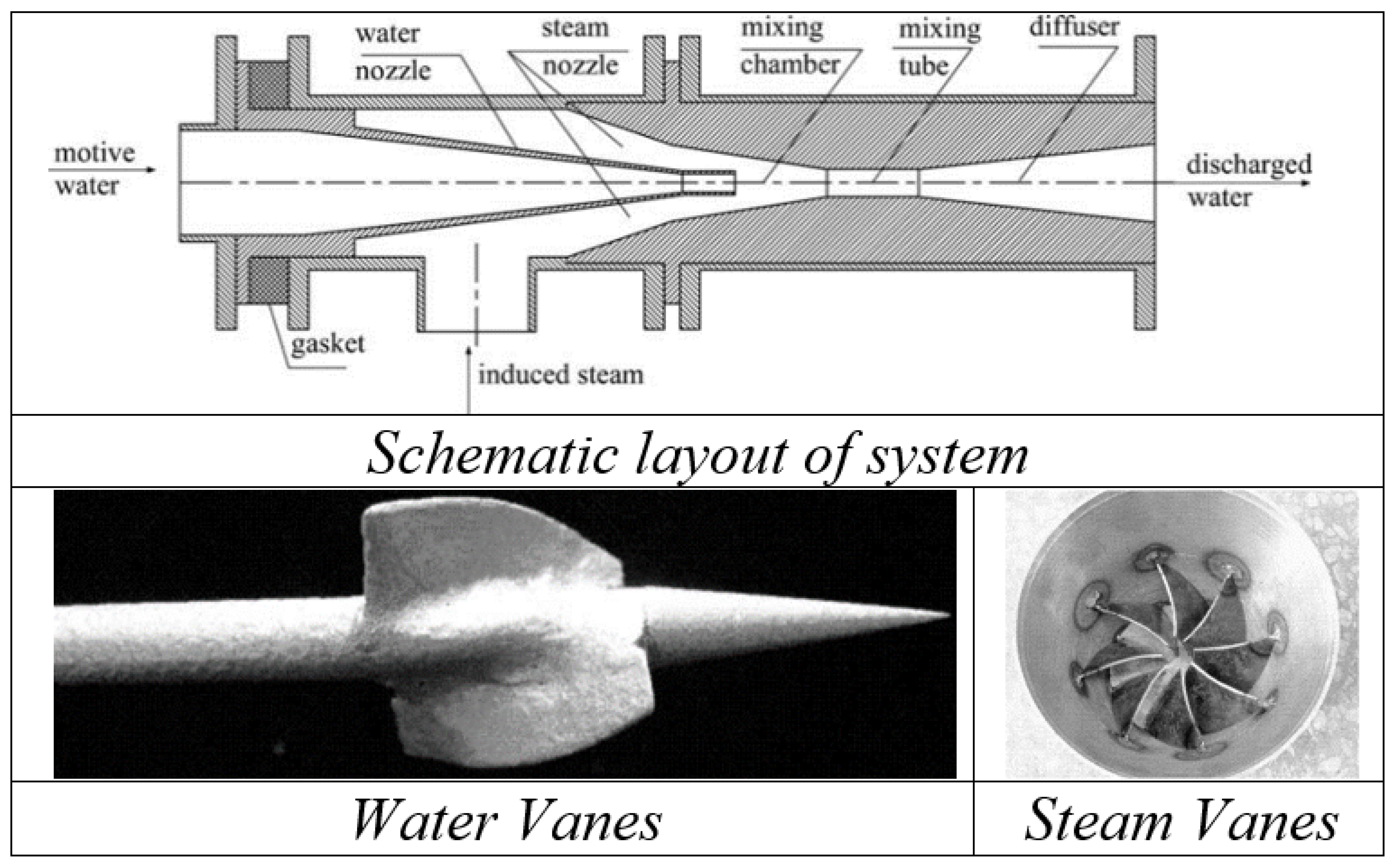
Yan et al. [68] studied the effect of swirling vanes (for both steam and water) on injectors with central water jets (Figure 14). Two swirling water vanes were present at the beginning of nozzle throat while eight steam swirling vanes were present, which caused disturbance in the velocity field inducing vortexes when flow passes through it. Observations for entrainment ratio and resistance coefficient were performed for an inlet pressure of steam and water and temperature. Water swirling vanes were found to be efficient in improving entrainment ratios, exergy and resistance coefficients, while steam swirling vanes caused degradation in performance.
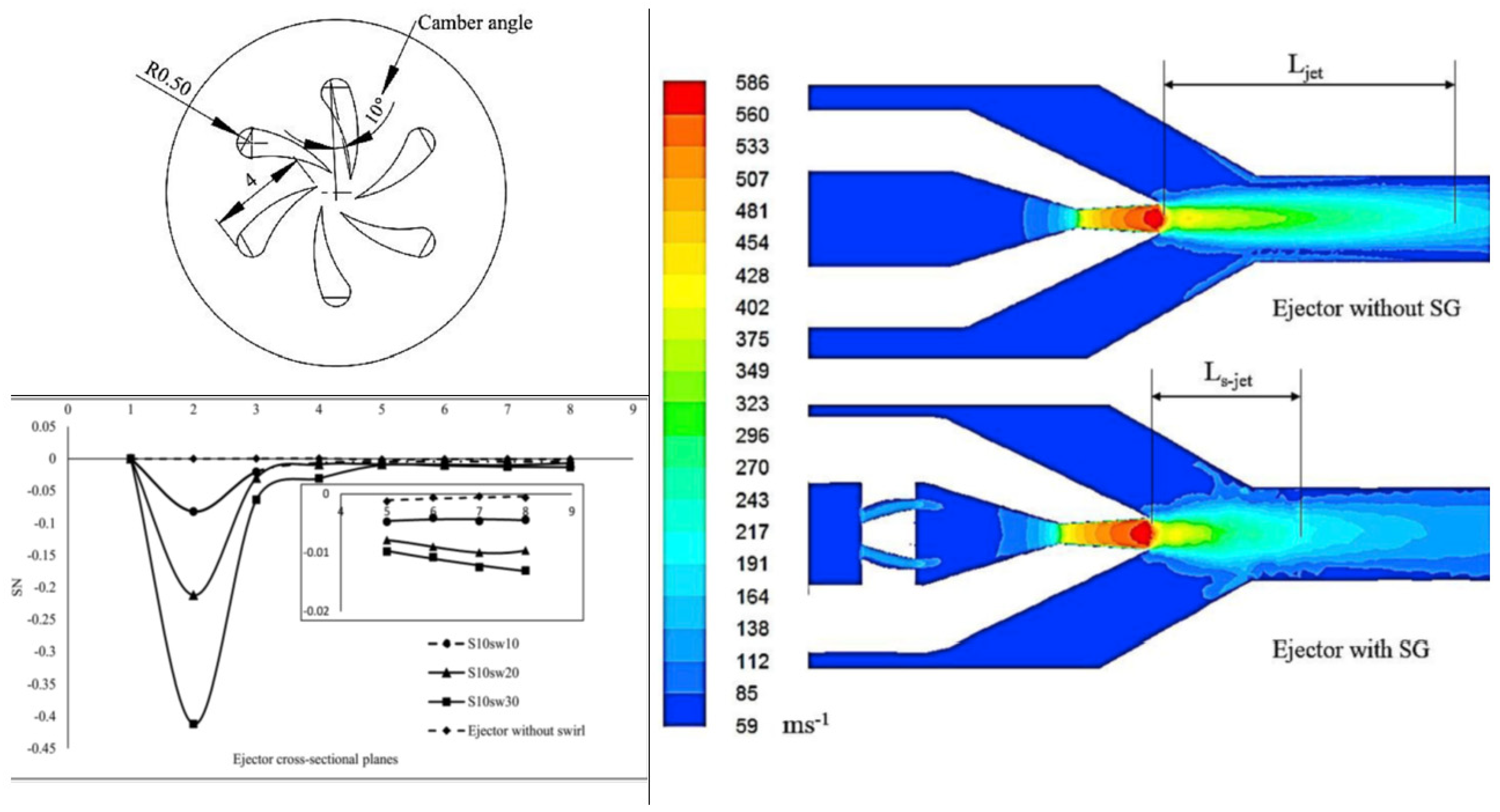
Banu et al. [69] focused on an air ejector system to analyze the influence of swirl for prospective application in vapor jet refrigeration. A three-dimensional numerical approach basis, with and without swirl, has been studied and verified through PIV technique. Figure 15 depicts the aerofoil cross-sectioned swirl generators, type-I and type-II, implemented in the system, placed at convergent section upstream. For geometry with primary nozzle diameter and area ratio of 3.2 mm and 2.56, an air compressor system with 100 L reserve was used in a transparent system. Primary flow measurement was performed through rotameter while secondary is measured with an orifice meter. With an increase in radial velocity compared to no swirl, there has been an enhancement of performance by 5% [70], 2% and <2% for cases with type-I, type-II with 5 vanes and type-II with 3 vanes.
Banu et al. [71], performed 3D numerical simulations for a different arrangements of type-I swirl generators with sweep angles of 10°, 20° and 30°, discussed in [39] along with verification through PIV. The swirling intensity was quantified with the non-dimensional parameter swirl number (SN); a ratio of the axial flux of tangential momentum to axial momentum as defined by the following equation [72].
S N = 0 R ρ   U x   U θ   r   d A R 0 R ρ   U x 2   d A
Figure 16 shows a reduction in axial velocity with primary stream pressure due to decreasing static pressure at the throat, causing velocity decay exponentially along the ejector. A sweep of 30° in cavity type swirl generator showed 15% improvement in ER.
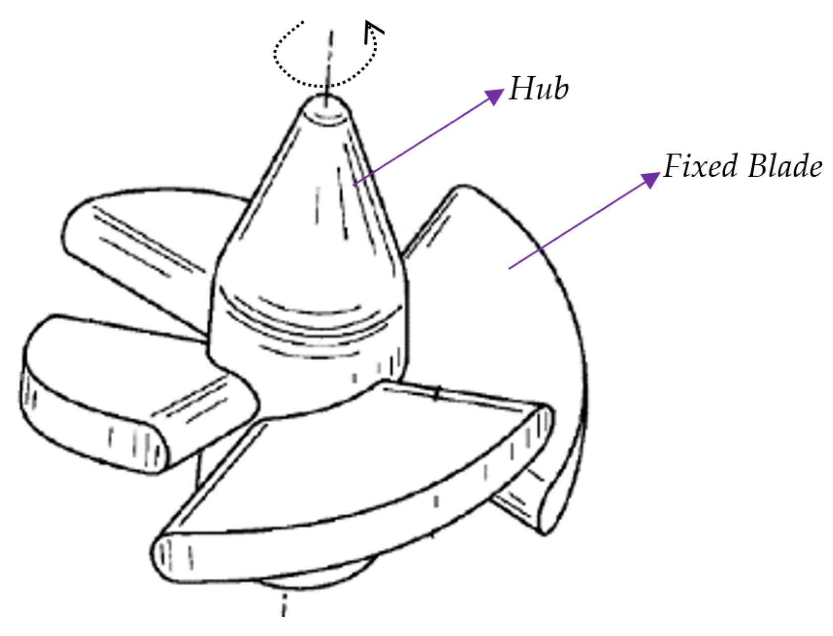
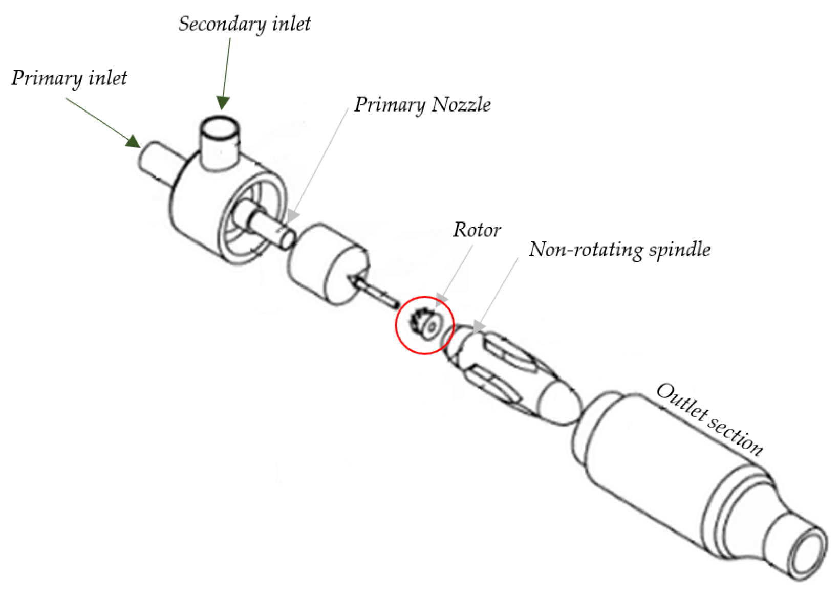
Chlappetta et al. [73] created a US patent for swirl vanes in vapor compression refrigeration systems shown in Figure 17. In addition to stationary swirling vanes, free spinning rotors were actively used in exchanging pressure and enhancing mixing. Garris et al. [74] mounted a free-spinning rotor on a fixed spindle (Figure 18). It uses non-steady fluid and supersonic flow principles to obtain compression of induced flow. This reduces losses during turbulent mixing, allowing better adiabatic efficiency during the topping cycle of rankine and gas cycles and refrigeration cycles. Hong et al. [75] updated the research status of this novel design computationally, with various geometrical arrangements; the geometry of rotor vanes was prioritized with leading and trailing edge and cross-sectional shape [76].

3.4. Throat Sizes

Water is an excellent refrigerant with high latent heat of vaporization, specific heat, suitable heat transfer characteristics, non-corrosive and adoptable by environmental concerns. In refrigeration systems, ejector performance is the deciding factor governing overall coefficient of performance. Ejector efficiency is governed by the entropy generation process, where conventional systems have two major sources: turbulent mixing and strong normal shock waves.
Alhussan et al. [77] varied the throat diameter ratio to investigate the structure of flow induction in an unsteady supersonic fluid with steam as the motive fluid. The pressure exchange ejector showed the mass flow ratio to be near to unit with high-pressure recovery.
In a vapor compression refrigeration cycle, throttling is a significant loss, hence modification through adaption of ejectors ensure optimized performance. Chaiwongsa et al. [78] studied the effect of throat diameter of the motive nozzle (0.8 mm, 0.9 mm and 1 mm) on CoP of a refrigeration systems with R134a for primary and secondary flow. A system with smaller diameter is found to have larger COP.
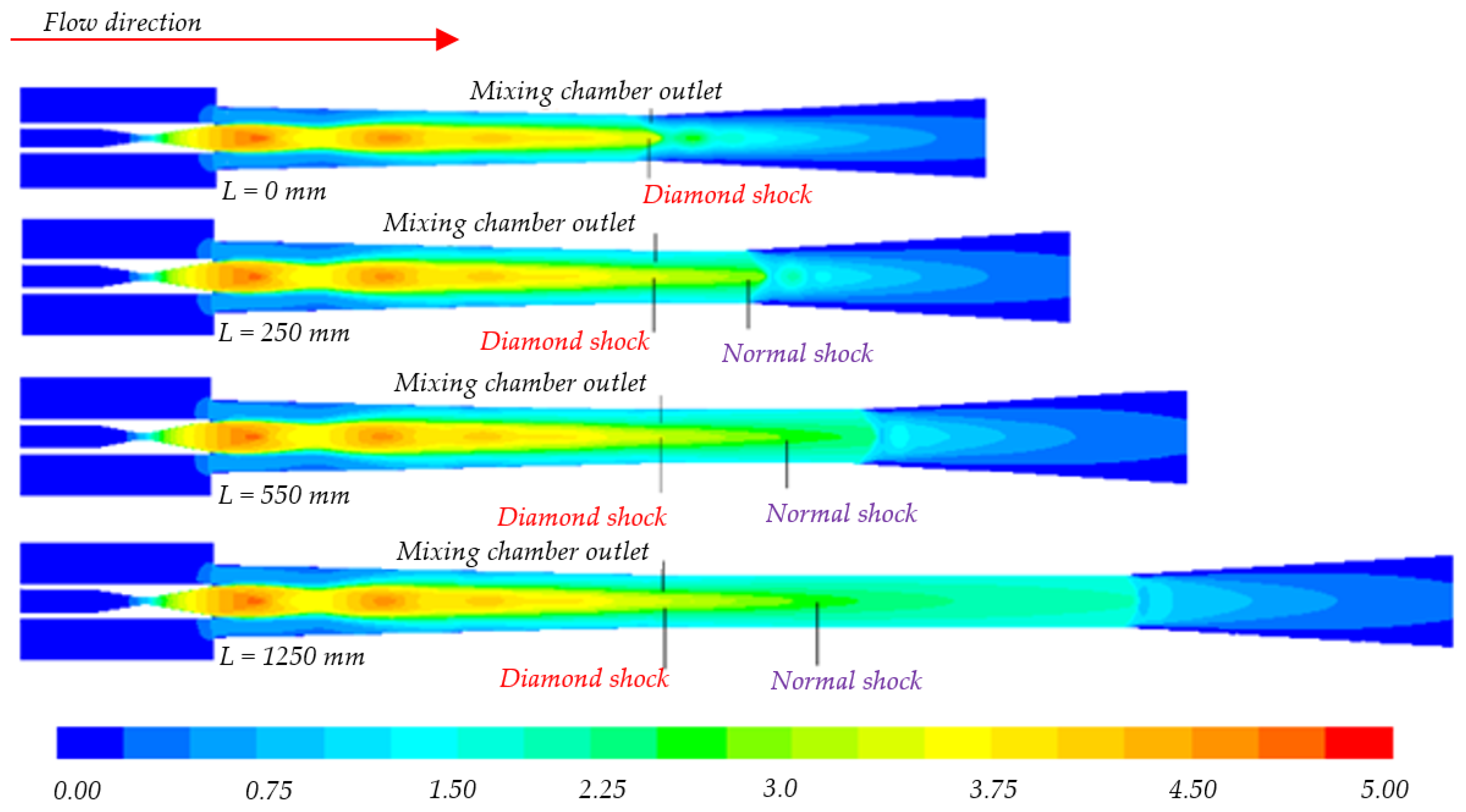
Bi et al. [79] developed a computational model to study the effect of throat diameter. Their results showed no significant change in the entrainment ratio location of diamond shock (abrupt standing shock wave variation) (Figure 19). Increasing length increased friction resistance, which eventually increased the critical back pressure up to its maximum value of operation and then decreases. For operational conditions, there is always an optimum point, and in this case, it was 550 mm.
Saini et al. [80] experimentally studied vacuum pressure for three throat lengths (10 cm, 20 cm and 30 cm) with constant throat diameter of 2 cm. Suction capacity was examined based on the absorbed weight of saw dust from the suction port. At 30 cm, a minimum pressure of 87.5 kPa and maximum suction of saw dust 32.2 grams were measured, as compressive strength at the top of the ejector will be converted to flow velocity with longer length.
Ren et al. [81] used a two-throat nozzle ejector in a TPERC (two-phase ejector refrigeration cycle) system and experimentally observed the consequent entrainment ratio using R134a refrigerant. Figure 20 provides the geometric description for de Laval and two throat nozzles, in both cases entrainment ratio was increased with cross-sectional area, but the value was larger (i.e., 0.375) for the two-throat system.
Wang et al. [82] used compressible turbulent flow with a real-gas model on a structured meshed 2D geometry for a solar-driven air conditioner system. Entrainment ratios for throat diameters 11, 12, 13, 14, 15, 16, 17 and 18 mm were analyzed and found to increase up to 17 mm before decreasing at 18 mm. At 11 mm, ER was negative and reached a peak value of 0.52 at 17 mm. In a larger diameter, the back pressure decreased from 0.133 to 0.085 MPa; while the operating condition of the condenser was 0.094 MPa, hence it is a priority to have critical back pressure simultaneously calculated along with entrainment ration to ensure the performance of ejectors. A larger throat diameter may not lead to better performance of ejectors.

4. Flow in Ejectors

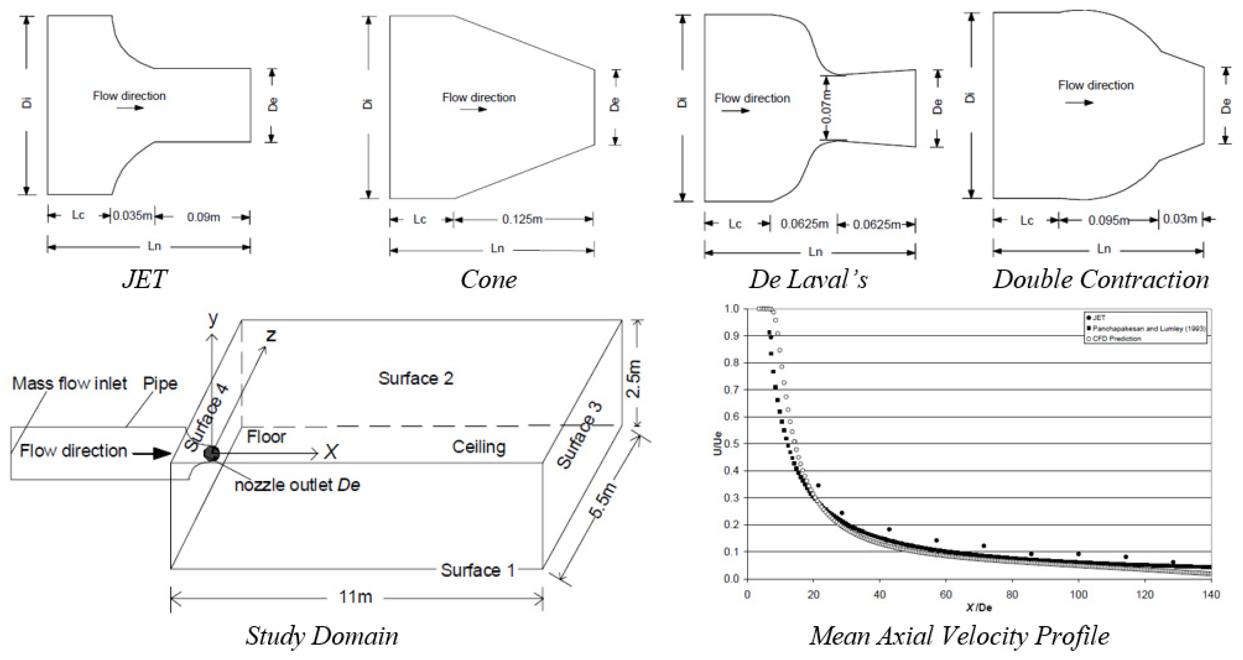
Khan [83], 2007, studied the effect of upstream nozzle geometry on air flow jets and temperature distribution in an enclosed space, with experimental validation of standard case and computational analysis using an RNG k-ε model. The study focused on axial mean streamwise velocity decay, mass entrainment, turbulence characteristics and temperature distribution in the closed space. The presence of three zones in free jet at nozzle exit (core zone, transition zone and main zone) was also discussed. Higher decay in axial mean velocity increase in length of potential core, reduction in throw and adverse effect on near flow field mixing was found. Potential core length was found to be lowest for double contraction and highest for de Laval’s nozzle. For turbulence kinetic energy, the highest value is observed for double contraction. A significant increase in TKE with a change in X/De was reported (Figure 21).
Liao et al. [84], 2017, studied the flow field of a nozzle water jets based on a mathematical model adhering to the theory of hydrodynamics. The study was focused on the impact of convergence angle and diameter of nozzle on water jet flow field.
In a water jets, the longest instance of acceleration was found with a 13° angle where the water jet velocity is maximum and forms longest core length. When increased to 30° and 60° the velocity core length and acceleration length decreased. For diameter variation it has also been summarized, that with large nozzle diameter, higher axial pressure can be achieved. Figure 22 shows the nozzle geometry and contour plot.
Kwidzinski [85] developed a mathematical model to predict the flow parameters in a characteristic cross-section of steam water injector (Figure 23). It is a steam driven system with accelerated and expanded steam being mixed with water, which is being drawn due to low static pressure at MC. Two phases at different temperature and velocities exchange mass, momentum and energy, during condensation. With pressure wave developed post t, two-phase flow gets compressed, with decreasing flow velocity and complete condensation.
Despite having a simple structure, two-phase mixing and condensation is a complex phenomenon to describe as this includes mechanical and thermodynamics in-equilibrium, heat transfer between fluids and fluid flow properties. The developed model has good convergence for injectors of motive steam, which expands in the steam nozzle to a sub- or supercritical velocity. The model solved mass, momentum and energy transfer between the domains, where segments were divided into various control volumes: water nozzle, steam nozzle, mixing chamber, condensation wave region and diffuser. The system development was based on the following assumptions: adiabatic system of steam nozzle, constant pressure outlet of water and steam nozzle with negligible effect from irreversible thermal losses at water nozzle and presence of saturated vapor phase homogeneous mixture at the throat in the mixing chamber. The model can predict outlet conditions based on inlet inputs.
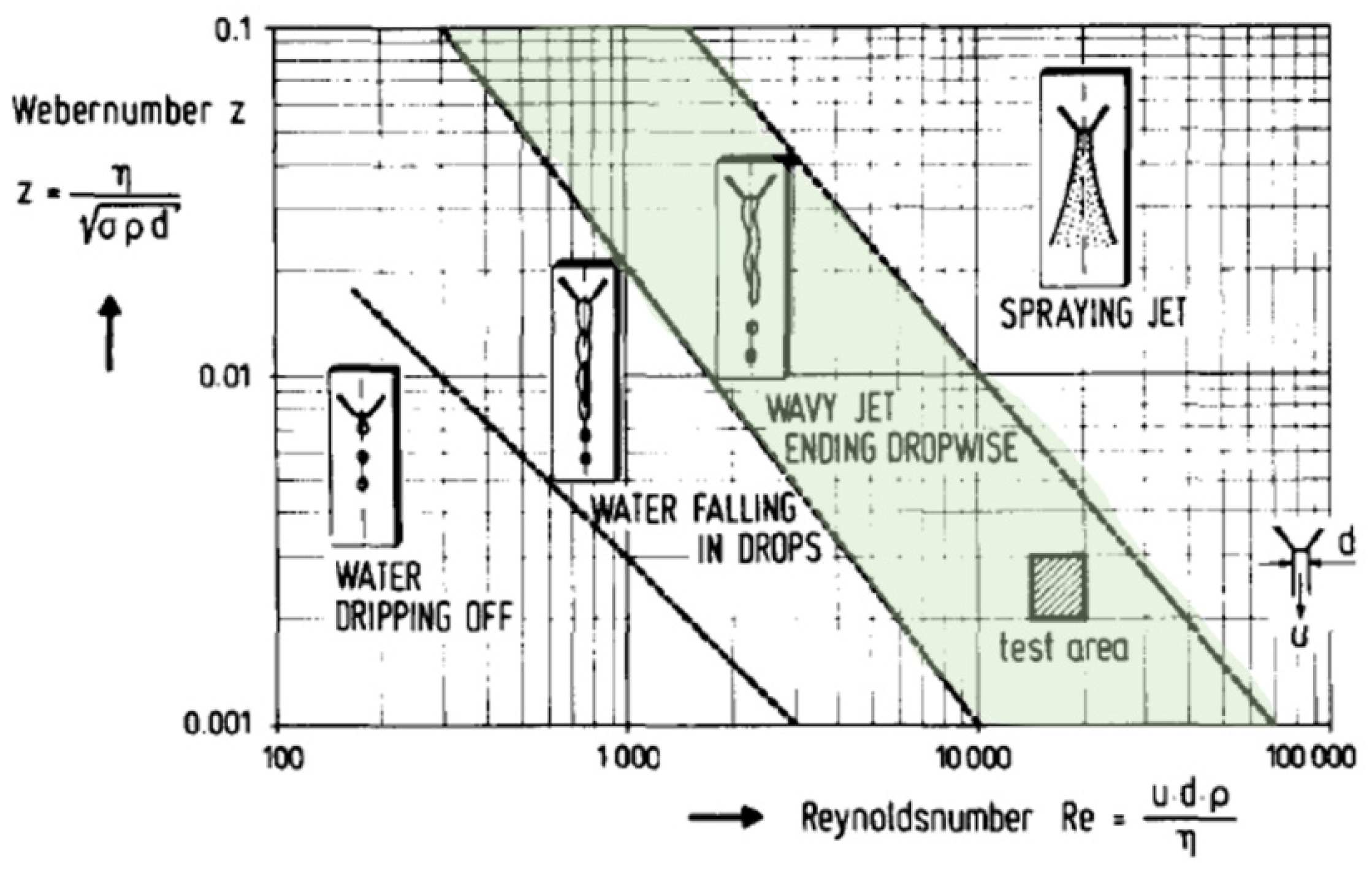
Schio et al. [86], presented a zero-dimensional mixing model of liquid water and steam, based on thermodynamics analytical study compared with experimental results, relating to time dependency of experimental pressure and theoretical internal energy. Fuchs et al. [87] studied water jet flow in a vacuum, for dumping excess water in a space lab cabin into space. Primarily, the differences for decomposition in atmosphere and vacuum were suggested. Atmospheric deposition is best described in Figure 24. The flow in the vacuum exists in the nozzles in bundled form but abruptly bursts to droplets. This bursting occurs at a certain point downstream, where the location is dependent on stagnation pressure, temperature, nozzle shape and gas content.
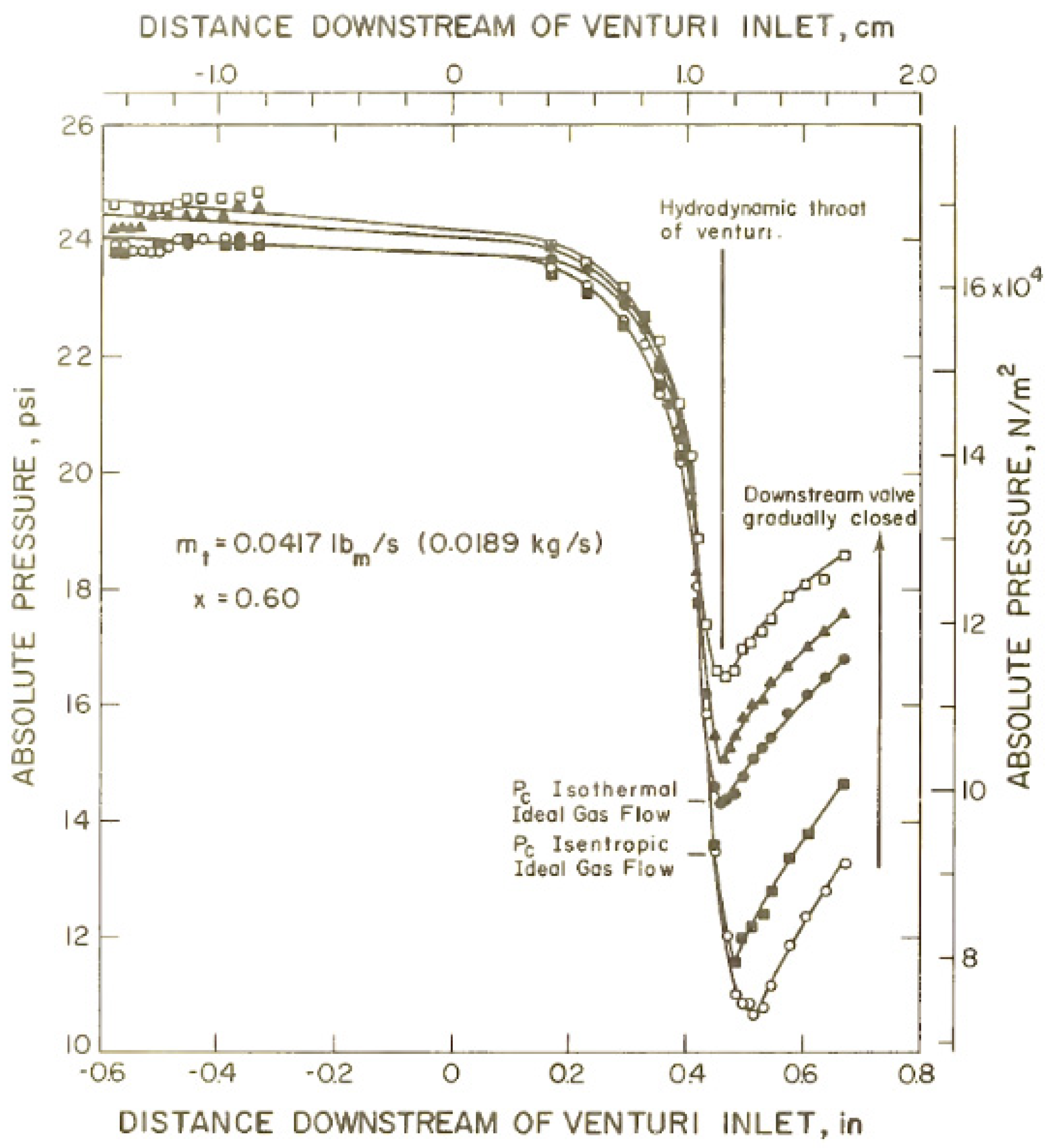
Smith et al. [88] carried out the second part of the two-phase critical flow program of the US National Bureau of Standards, Department of Commerce, based on the hypothesis that—at higher quantities, behavior of gas controls critical two-phase flow. Past literature focused on the point of occurrence of critical flow, study of which has several limitations: flow condition varies over the downstream region since the system does not achieve complete equilibrium during the process. The author identified another prime issue as being identification of phase velocities, which so far, has been identified with uncertain data. Figure 25 shows the downstream pressure distribution in the system which concluded that gas flow behavior is the prime factor that governs the critical flow of the two-phase system. The analytical model for critical pressure ratios, considered with energy and momentum, agreed with experimental results, neglecting mass transport (vaporization and condensation).
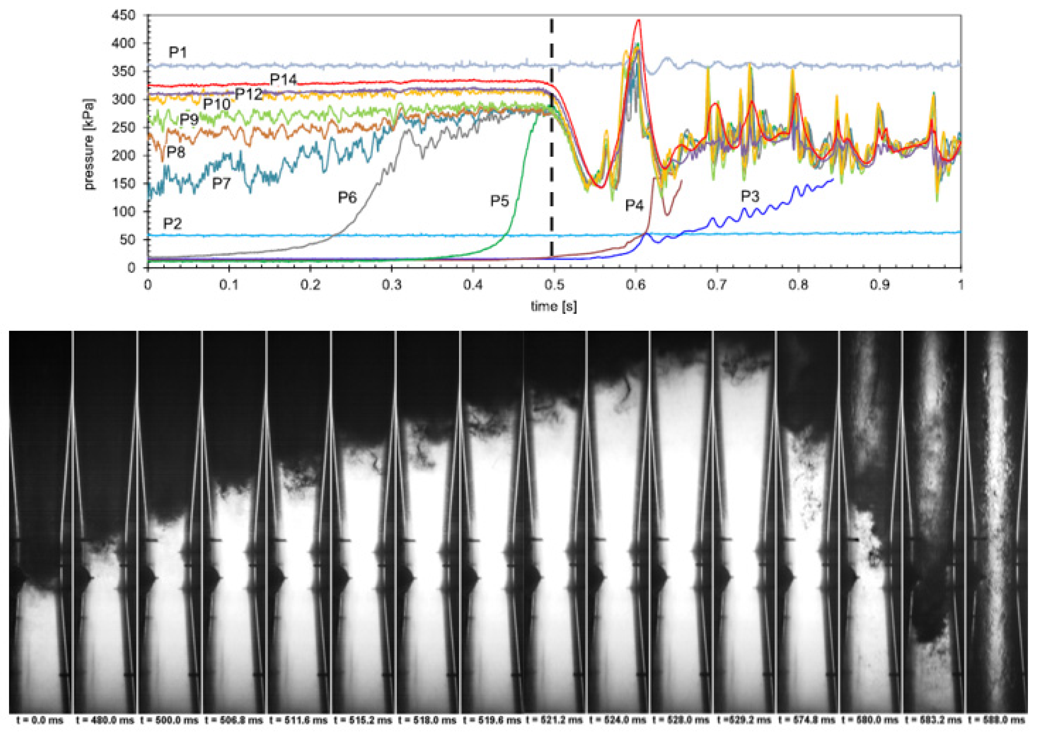
Kwidzinski [89] experimentally investigated the effect of condensation wave structure in steam-water injector systems, using high-speed videography technique, along with parallel monitoring of pressure, temperature and flow rates. The system under study has five main parts: converging-diverging steam nozzle, water nozzle, mixing chamber, throat and diffuser as shown in the Figure 26 with locations of pressure and temperature sensors.
On varying the back pressure at constant operating conditions, there was a shift in condensation wave towards the mixing chamber and better condensation formed at the diffusers. Flow instability was induced after introducing flow instability with a gradual rise in back pressure, termed stalling. The Figure 27 shows transient pressure recording during stalling at inlet steam pressure and flow of 360 kPa and 120 kg/h, respectively, with inlet water temperature and flow of 15 °C and 3000 kg/h. When completely mixed flow in the mixing chamber occurs, the flow is supercritical, where vapour condenses in a narrow shock region, resulting in pressure pulsation, with its amplitude dependent on an axial location in the system.
Shah et al. [90] implemented a thermal equilibrium model for direct contact condensation (DCC) of steam in subcooled water, which is a two-resistance model. This includes heat transfer on both interfaces considering variable diameter of steam bubbles. The two-phase Eulerian model has a separate set of equations for mass, momentum and energy transfer, phase coupling is defined through interphase exchange coefficients. A DCC model as condensation model and symmetric model for interphase drag was implemented for computation. The condensation model considered interfacial area, interfacial heat transfer coefficient and interfacial mass transfer as three key parameters. The interfacial area is defined through variable steam bubble diameter as a local liquid sub cooling linear function. Convective heat transfer coefficient in the continuous fluid was defined through Nusselt number with a separate set of calculations from one phase to another. Mass transfer is defined through a user defined function (UDF) of the solver system. The solution of three-dimensional flow study was compared with published results and was found to have agreement of supersonic steam jet condensation into subcooled water.
Shah et al. [91] experimentally and numerically studied flow in steam jet pump systems, for the application of radioactive and hazardous liquids (Figure 28). A Eulerian two-phase flow with a direct contact condensation model was used to solve the 3D flow in the system. Each phase was defined with separate momentum, continuity and energy equations, with phase coupling through pressure and interphase exchange coefficient and turbulence through k-ε model. Drags between phases were defined with a symmetric model. The condensation model by Shah et al. [90] was implemented in this study. The rate of energy transfer during the direct contact condensation was dependent on interfacial area, interfacial heat transfer coefficients and interfacial mass transfer. Boundary conditions of steam and water pressure were defined at the inlet, pressures at outlets and the walls were modelled to be adiabatic.
Shah et al. [92] also studied the effect of a mixing section length on direct contact condensation in stream jet pumps. Mixing was found to be strongly dependent on section length which in turn induces higher suction for the water nozzle; hence, with proper modification better design can be achieved. Figure 29 shows the axial pressure measure.
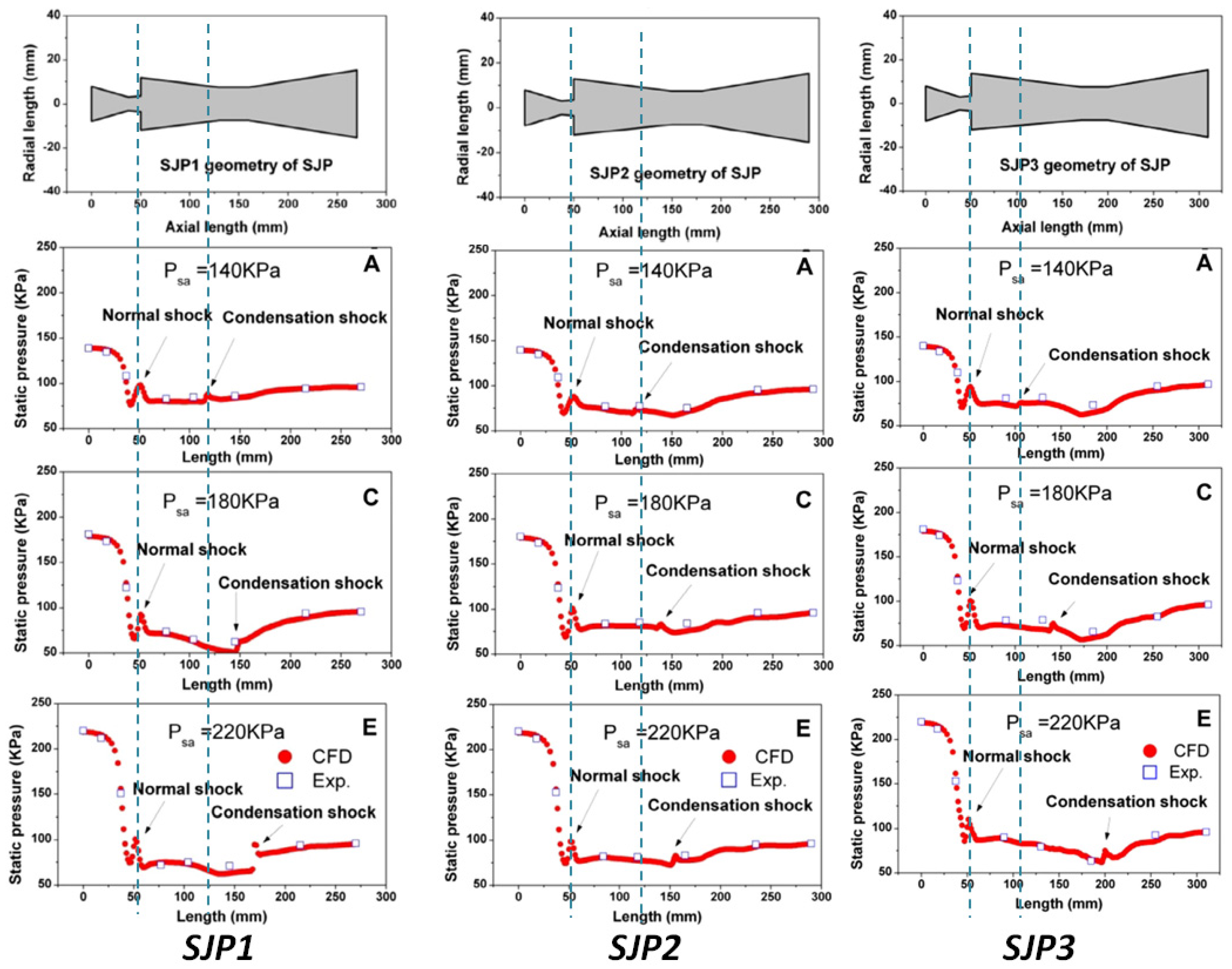
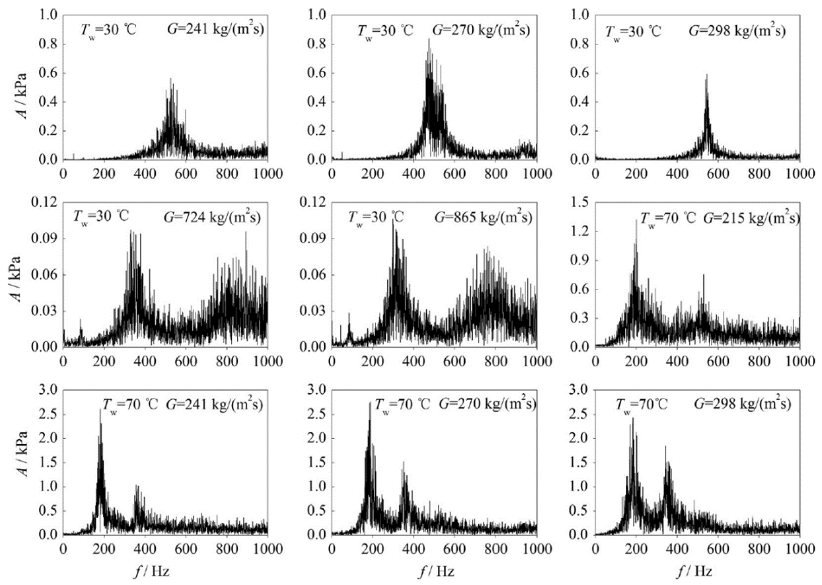
Yang et al. [93] performed an experiment with simplified test setup to predict pressure oscillation during direct contact condensation of steam jet in water. The high-speed videography technique in SS setup had a rectangular flow section and de Laval nozzle, with adjacent side fitted with glass for observation. Non-invasive pressure measurement techniques were implemented for simultaneous pressure measurement (Figure 30). Post-processing of acquired data was performed with image processing (grey scaling image) and FFT of pressure data. Two dominant frequencies were observed: the first was due to periodic variation of condensation jet length and the second with large bubbles in the steam plume. The study focused on the first dominant frequency, which is at constant position despite observation post variation of x/de ratio. Through high-speed videography, it was observed to have undistinguished separation layers between motive and suction fluid in subsonic flow, this, in turn, was found to be distinguished when flow becomes supersonic. At the interface region with steam flux rate of 250 kg/m2s, water Reynolds number 148,000 and water temperature 45 °C, formation of tail during two-phase mixing has been discussed, where water surrounds steams bubbles from the tail of steam and condensation occurred. This phenomenon occurs at a frequency of 581 Hz which was the first predominant frequency caused by periodical variation of interface tail. This frequency increased with increasing water Reynolds number and decreased with increasing water temperature and steam mass flux.
During pressure oscillation, two dominant frequencies were observed, the first is due to periodical variation of steam plume and the second due to generation and rupture of bubbles surrounded by water. Qiu et al. [94] performed an experimental study of dominant pressure oscillation frequency for the sonic steam jet in subcooled water. At low-pressure oscillation frequency, resonance can occur with the wall which may result in major fatality in nuclear power plants. The test setup had flow loop, sonic nozzle, and flow data acquisition module, including high-speed camera (1000 FPS) videography technique. Flow meter, pressure transducer and temperature sensor accuracy were calculated to be 1%, 0.2% and 0.5 K respectively. The supersonic saturated stem was injected into the subcooled water pool, resulting in a rise in water temperature due to condensation. With an increase of water temperature, steam mass flux was adjusted to attain the required test condition. The expression of this frequency was dependent on operating conditions, with low water temperature and steam mass flux, single frequency is expressed while with higher above values the second one expresses. There have been several statements, for amplitude of frequency, but experimental observations show that either one can have higher amplitude based on operating conditions. The frequency is shown in Figure 31.
Zhdanov et al. [95] performed a simplified experiment on mixing of coaxial jet mixer flow for two mixing regimes (Figure 32). The first regime was just beyond the nozzle with recirculation and the second is while the jet mixes with secondary flow without recirculation, over a range of 0.1 < x/D < 9.1 in the system. The formation of the second regime was initiated by interaction between backflow and co-flow. Measurements were taken with the aid of laser Doppler anemometer and LIF method with rhodamine 6G solution.

5. Operational Problems and Challenges in Ejector

Ejectors being a standard industrial product, exposed to prolonged operation, is natural experience operational issues. Research activities should be able to mitigate existing operational challenges and be prepared for forthcoming technical circumstances. Since industrial problems are not reported much in academic publications, limited issues were noted. We examine industrial problems associated with the ejector application.
Lines et al., at the Graham Corporation [96], examined the ejector’s operational challenges and troubleshooting during vacuum generation in industries. The backflow through the suction chamber can be observed while operating at lower steam pressure; optimum operating ranges were defined and was essential to operate within the range. Instabilities were observed in the ejector if the discharge pressure exceeds the maximum discharge pressure (MDP) at the outlet. The loose nozzle and steam leakage lead to fouling of the system.
Lieberman [97] studied the four issues associated with vacuum ejectors in a refinery. Erosion in nozzle threads, sealing issue, quality of primary fluid and galvanic corrosion in the nozzle were the major problems. The galvanic corrosion in the primary nozzle can be reduced with superheated steam. The primary nozzle thread erosion or improper fitting affects the distance between nozzle and converging section affects sealing. A study by Unique Systems Incorporated [98] suggested periodic field checking of steam pressure and quality. The low-pressure steam and wet steam deteriorate the physical property and performance of the system. Inner wall corrosion is another important physical damage observed in the vacuum ejector. The periodic monitoring of diffuser throat and steam nozzle size was recommended. Engel et al. [99] studied the problems in design and operation of ejectors. The quality of primary flow was found to be the prime influencing factor in the performance. Hence, ensuring prolonged operation at a single designed point requires controlled input and continuous monitoring of deviation from the design point.

6. Ejector Based Membrane Distillation Process

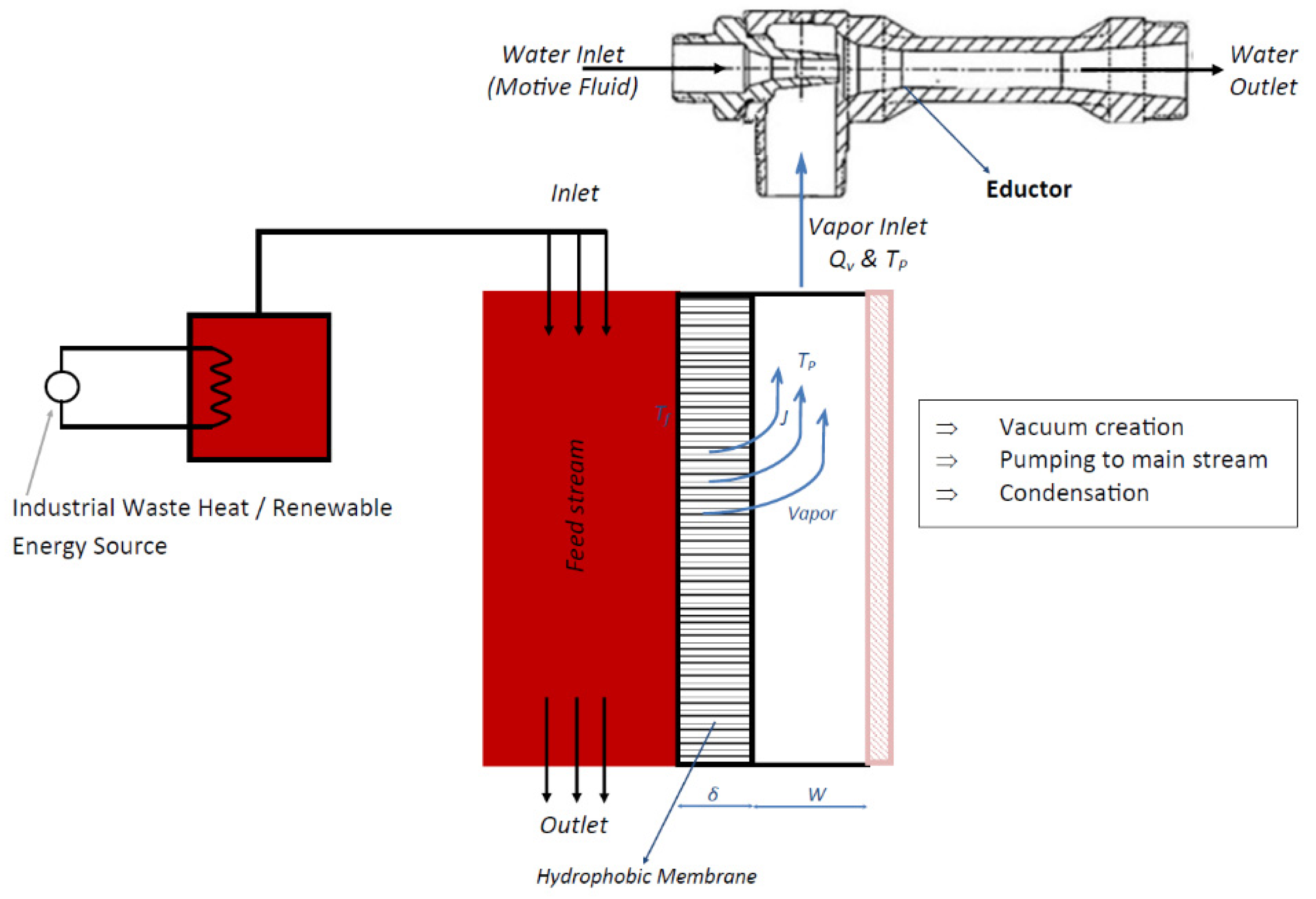
Membrane distillation desalination process is a freshwater production process by separation technique, driven by vapor pressure difference between the feed and permeate sides of the hydrophobic membrane [100]. This vapor pressure difference is maintained through the temperature difference between the two sides [101]. The vacuum membrane distillation (VMD) process is among the promising technologies, having comparatively lower convective heat loss and mass transfer resistance [102,103], which are operationally suitable for integration with ejectors. For a general VMD process, feed pressure and temperature, permeate side pressure, permeate vapor suction, condensation and freshwater transfer are prime operations and variables. Review of operations and construction of ejectors summarized the vacuum generation, pumping, mixing, heat and mass transfer and higher-pressure discharge capability of ejectors, which adheres completely with the permeate side operational requirements of a VMD. Figure 33 is the technical layout of ejectors based on the VMD process. The vapor separates from the feed through a hydrophobic membrane (details on VMD can be accessed through [104,105]), since the permeate chamber pressure is lower than the vapor pressure, condensation does not occur, vapor is entrained to ejectors (where there is already primary fluid flow), primary and secondary fluid mixes, transfers mass followed by heat and finally discharges single phase fluid at pressure higher than the secondary pressure.
Numerical modelling based on the maximum suction pressure developed by ejectors and operation of vacuum membrane distillation were performed as a pre-estimation for viability of operation of such a system. Figure 34 is the numerical algorithm implemented for this application. Permeate side pressure were imported from maximum vacuum pressure from the ejector [106,107,108].

7. Conclusions

Ejectors create a low-pressure zone by utilizing pressure energy in the motive fluid to perform suction of secondary fluid in mainstream, established to be a well-developed sustainable industrial application. The objective of this review is to identify implemented research prospects of ejectors on enhancing current performance of ejectors, for their prospective application in the water desalination process. The major findings of this review are listed below:
  • Ejectors are in successful applications for vacuum generation, secondary fluid pumping, mixing and heat and mass transfer.
  • The operational characteristics were found to be dependent on geometric shape and sizes. Primary nozzle geometry and position, secondary inlet geometry and size, mixing chamber D/L ratio, length of throat and diffusing length were identified to be prime influencing factors. In addition, dynamics and property of primary flow were other associated factors.
  • The operational requirement of VMD completely adheres with the outcome characteristics of ejectors. Hence integration of ejectors with VMD can result in sustainable freshwater production. Possible application in industrial wastewater treatment, could bring about significant impact. Section 5 of the work aids the viability of the system.
  • Although the functionality satisfies operationality of the desalination process; the ejectors were never focused on for this specific application. Hence, design optimization is essential, for possible enhanced capacity harnessing. The following criteria are to be prioritized:
    • Pressure recovery—the major drawback of the system is in pressure recovery at the outlet. Most of the energy is lost when fluid passes from high pressure to low pressure (inlet to nozzle outlet) and returns to high pressure (suction to outlet).
    • Mixing enhancement—heat and mass transfer is directly proportional to the mixing index. The quality of mixing increases the effectiveness of the system. Technically, increasing the mixing layer thickness at two-phase interfaces ultimately increases it.
    • Interphase shear stress—lagging and leading velocity difference at the interface absorbs energy in motive fluid due to interphase shear stress. Hence, increasing the velocity of entrained phase will increases the entrainment in the system.
    • Suction enhancement—the most influential factor is suction capacity, flux, needs to be balanced with entrainment ratio, to ensure all VMD flux transfer will reach inside the ejector.
  • Achievement of (iv) criterion, will support wider industrial acceptance and application. In addition, the methodology to achieve it, will further support in application-based design, analysis and manufacturing for one or multiple functionalities of the ejectors (vacuum generation, mixing or heat and mass transfer, etc.)
However, the modification in design may introduce design and operational complexity in the technology, which might affect the simple design feature of the ejector. The enhanced performance must complement the design effort aimed at application viability.

Author Contributions

Conceptualization, R.K., A.D. and K.I.; original draft preparation, R.K.; Review and editing, A.D., Q.L.V., K.I. and B.Z., Supervision, A.D. and K.I. All authors have read and agreed to the published version of the manuscript.

Funding

This research received no external funding.

Institutional Review Board Statement

Not applicable.

Informed Consent Statement

Not applicable.

Data Availability Statement

Not applicable.

Conflicts of Interest

The authors declare no conflict of interest.

References

  1. University of Cambridge. Industrial Sustainability. 2016. Available online: https://www.ifm.eng.cam.ac.uk/research/industrial-sustainability/ (accessed on 10 July 2018).
  2. Battles, S.J.; Burns, E.M. United States Energy usage and efficiency: Measuring changes over time. Energy Inf. Adm. 1999. [Google Scholar]
  3. Rahimi, B.; Christ, A.; Regenauer-Lieb, K.; Chua, H.T. A novel process for low grade heat driven desalination. Desalination 2014, 351, 202–212. [Google Scholar] [CrossRef]
  4. Zhang, X.; Liu, Y.; Wen, X.; Li, C.; Hu, X. Low-grade waste heat driven desalination with an open loop heat pipe. Energy 2018, 163, 221–228. [Google Scholar] [CrossRef]
  5. WWAP UNESCO. The United Nations World Water Development Report 2019: Leaving No One behind; UNESCO: Paris, French, 2019. [Google Scholar]
  6. Haddad, C.; Perilhon, C.; Danlos, A.; François, M.-X.; Descombes, G. Some Efficient Solutions to Recover Low and Medium Waste Heat: Competitiveness of the Thermoacoustic Technology. Energy Procedia 2014, 50, 1056–1069. [Google Scholar] [CrossRef]
  7. Alfa Laval. How Technology Can Help Combat Water Scarcity. 2019. Available online: https://www.alfalaval.com/media/stories/municipal-wastewater-treatment/how-technology-can-help-combat-water-scarcity/ (accessed on 25 April 2019).
  8. Population Pyramid. Population Pyramids of the World from 1950 to 2100. 2019. Available online: https://www.populationpyramid.net/world/2019/ (accessed on 1 October 2019).
  9. INTERREG. Available online: https://www.interreg-central.eu/Content.Node/CE-HEAT/Low-grade-waste-heat-utilization-in-the-European-Union.html (accessed on 28 June 2017).
  10. Youssef, P.; Al-Dadah, R.; Mahmoud, S. Comparative Analysis of Desalination Technologies. Energy Procedia 2014, 61, 2604–2607. [Google Scholar] [CrossRef] [Green Version]
  11. Deshmukh, C.; Boo, V.; Karanikola, S.; Lin, A.; Straub, T.P.; Tong, D.; Warsinger, M.; Elimelech, M. Membrane distillation at the water-energy nexus: Limits, opportnities and challenges. Energy Environ. Sci. 2018, 11, 1177–1196. [Google Scholar] [CrossRef]
  12. Stefan, E.; Neal, L. Review of recent developments in advanced ejector technology. Int. J. Refrig. 2016, 62, 1–18. [Google Scholar]
  13. Takeya, Y.; Miwa, S.; Hibiki, T.; Mori, M. Application of steam injector to improved safety of light water reactors. Prog. Nucl. Energy 2015, 78, 80–100. [Google Scholar] [CrossRef]
  14. Chunnanond, K.; Aphornratana, S. Ejectors: Applications in refrigeration technology. Renew. Sustain. Energy Rev. 2004, 8, 129–155. [Google Scholar] [CrossRef]
  15. He, S.; Li, Y.; Wang, R. Progress of mathematical modeling on ejectors. Renew. Sustain. Energy Rev. 2009, 13, 1760–1780. [Google Scholar] [CrossRef]
  16. Sarkar, J. Ejector enhanced vapor compression refrigeration and heat pump systems—A review. Renew. Sustain. Energy Rev. 2012, 16, 6647–6659. [Google Scholar] [CrossRef]
  17. Besagni, G.; Mereu, R.; Inzoli, F. Ejector refrigeration: A comprehensive review. Renew. Sustain. Energy Rev. 2016, 53, 373–407. [Google Scholar] [CrossRef] [Green Version]
  18. Aidoun, Z.; Ameur, K.; Falsafioon, M.; Badache, M. Current advances in Ejector Modeling, Experimentation and Applications for Refrigeration and Heat Pumps. Part 1: Single-Phase Ejectors. Inventions 2019, 4, 1–73. [Google Scholar] [CrossRef] [Green Version]
  19. Snell, J.B. Mechanical Engineering: Raiways; Arrow Books: London, UK, 1973. [Google Scholar]
  20. Berkeley, F.D. Ejectors; Graham Manufactring Company Inc.: Batavia, IL, USA, 1958; Available online: https://www.graham-mfg.com/usr/pdf/TechLibVacuum/25.PDF (accessed on 1 June 2019).
  21. Shaozhi, Z.; Luo, J.; Wang, Q.; Chen, G. Step utilization of energy with ejector in a heat driven freeze dring system. Energy 2018, 164, 734–744. [Google Scholar]
  22. Macia, L.; Castilla, R.; Gámez, P.J. Simulation of ejector for vacuum generation. In Proceedings of the IOP Conference Series: Materials Science and Engineering; IOP Publishing: Bristol, UK, 2019; Volume 659, pp. 1–7. [Google Scholar]
  23. Kumar, R.A.; Rajesh, G. Physics of vacuum generation in zero-secondary flow ejectors. Phys. Fluids 2018, 30, 066102. [Google Scholar] [CrossRef]
  24. Knight, J.; Met, M. The use of steam Ejectors for the Vacuum Degassing of steel. Proc. Inst. Mech. Eng. 1966, 181, 225–241. [Google Scholar] [CrossRef]
  25. Kuznetsov, V.A.; Kats, Y.L. Economical vacuum degassing of steel with the use of mechanical pumps. Metallurgist 2007, 51, 220–225. [Google Scholar] [CrossRef]
  26. Winter, R.D.; Caldwell, J.E. Vacuum Degassing with Ejector Technology; National Forge Company: Irivne, CA, USA, 1997. [Google Scholar]
  27. Freedman, B.Z.; Lior, N. A Novel High-Temperature Ejector-Topping Power Cycle. J. Eng. Gas Turbines Power 1994, 116, 1–7. [Google Scholar] [CrossRef]
  28. Garris, C.A. Pressure Exchange Ejector. USA Patent US7497666B2, 20 September 2005. [Google Scholar]
  29. Oliveira, A.; Afonso, C.; Matos, J.; Riffat, S.; Nguyen, M.; Doherty, P. A combined heat and power system for buildings driven by solar energy and gas. Appl. Therm. Eng. 2002, 22, 587–593. [Google Scholar] [CrossRef]
  30. Zhang, C.; Lin, J.; Tan, Y. A theoretical study on a novel combined organic Rankine cycle and ejector heat pump. Energy 2019, 176, 81–90. [Google Scholar] [CrossRef]
  31. Zhang, K.; Chen, X.; Markides, C.N.; Yang, Y.; Shen, S. Evaluation of ejector performacne for an organic Rankine cycle combined power and cooling system. Appl. Energy 2016, 184, 404–412. [Google Scholar] [CrossRef] [Green Version]
  32. The Process Piping. Introduction to Priming in Pumps, The Process Piping. 2020. Available online: https://www.theprocesspiping.com/introduction-to-priming-in-pumps/ (accessed on 17 October 2020).
  33. Sulzer. Sulzer Ejector for Priming. 2020. Available online: https://www.sulzer.com/china/-/media/files/products/pumps-accessories/pump-and-lifiting-station-accessories/brochures/ejectorforpriming_e10514.ashx?la=en (accessed on 17 October 2020).
  34. Techmon. Variator Priming Ejector–VG. 2020. Available online: https://www.techmon.eu/products/varitor-priming-ejector-vg/ (accessed on 7 July 2020).
  35. Iron Pump. P-type Ejectors—Dimensions & Weights. 2020. Available online: https://ironpump.com/images/Products/Ejector-P-Type-Data-Sheet.pdf (accessed on 17 October 2020).
  36. G.A. Hanrahan Pty. Ltd. Ejector for Steam or Air Operation. 2020. Available online: http://www.hanrahanengineering.com.au/brown-ejector/ (accessed on 17 October 2020).
  37. Prime Tech Ejectors. Pump Priming Eductor-E-PM-3501/3502. 2020. Available online: http://primetechejectors.com/pdf/pump_priming_eductor.pdf (accessed on 17 October 2020).
  38. Ullah, K.R.; Saidur, R.; Ping, H.W.; Akikur, R.K.; Shuvo, N.H. A review of solar thermal refrigeration and cooling methods. Renew. Sustain. Energy Rev. 2013, 24, 499–513. [Google Scholar] [CrossRef]
  39. Vakiloroaya, V.; Samali, B.; Fakhar, A.; Pishghadam, K. A review of different strategies for HVAC energy saving. Energy Convers. Manag. 2014, 77, 738–754. [Google Scholar] [CrossRef]
  40. Fox Venturi Products, Pup Priming Ejectors, Fox Venturi Products. 2020. Available online: https://www.foxvalve.com/air-gas-steam-vacuum-ejectors/pump-priming-ejectors/ (accessed on 17 October 2020).
  41. SWT Water. Eductors. 2018. Available online: https://www.swtwater.com/catalog/eductors_index.htm (accessed on 7 September 2018).
  42. Cebeco. Products-Eductors. 2010. Available online: http://www.cebeco.com.au/products/eductors/jt-eductors (accessed on 28 July 2018).
  43. Schutte & Koerting. Eductors & Syphons–Water Jet Eductor. 2018. Available online: https://www.s-k.com/eductors-syphons/water-jet-eductors.cfm (accessed on 15 January 2020).
  44. Fox Valve, Fox Mini-Eductors. 2017. Available online: https://www.foxvalve.com/mini-eductors/introduction/ (accessed on 1 April 2021).
  45. Bamford & Morris Ltd. Custom Eductor Solutions for Pumping Gases. 2018. Available online: http://www.bamfordandmorris.com/eductors-for-gas.html (accessed on 15 January 2020).
  46. Applied Vacuum. Liquid Eductors. 2017. Available online: http://www.appliedvacuum.co.za/products/liquid-educators/ (accessed on 5 January 2020).
  47. Boysan, F. A Two-Fluid Model for Fluent; Flow Simulation Consultants Ltd.: Sheffield, UK, 1990. [Google Scholar]
  48. Oh, J.-T.; Ngoc, C.N. Development of heat pump system using thermobank and ejector for heating room and cold storage. In Electric Vehicles and the Future of Energy Efficient Transportation; IGI Global: Hershey, PA, USA, 2015; pp. 784–802. [Google Scholar]
  49. AB Progetti, Liquid Ejectors. 2018. Available online: http://www.abprogetti.com/liquid-ejectors.html (accessed on 25 December 2020).
  50. Elbel, S.; Hrnjak, P. Ejector Refrigenration: An Overview of Historical and Present Developments with an Emphasis on Air-Conditioning Applications. In Proceedings of the International Refrigeration and Air Conditioning Conference at Purdue, West Lafayette, IN, USA, 14–17 July 2008. [Google Scholar]
  51. Chen, X.; Somer, S.; Worall, M.; Riffat, S. Recent developments in ejector refrigeration technologies. Renew. Sustain. Energy Rev. 2013, 19, 629–651. [Google Scholar] [CrossRef]
  52. Eames, W. A new prescription for the design of supersonic jet-pumps: The constant rate of momentum change method. Applied Therm. Eng. 2002, 22, 71–87. [Google Scholar] [CrossRef]
  53. Kitrattana, B.; Aphornratana, S.; Thongtip, T.; Ruangtrakoon, N. Comparison of traditional and CRMC ejector performance used in a steam ejector refrigeration. Energy Precedia 2017, 138, 476–481. [Google Scholar] [CrossRef]
  54. Kumar, V.; Singhal, G.; Subbarao, P. Realization of novel constant rate of kinetic energy change (CRKEC) supersonic ejector. Energy 2018, 164, 694–706. [Google Scholar] [CrossRef]
  55. Ariafar, K.; Toorani, A. Effect of nozzle geometry on a model thermocompressor performance—A numerical evaluation. In Proceedings of the Annual International Conference on Mechanical Engineering, Shiraz, Iran, 16–18 May 2012. [Google Scholar]
  56. Zare-Behtash, H.; Gongora-Orozco, N.; Kontis, K. Effect of primary jet geometry on ejector performance: A cold-flow investigation. Int. J. Heat Fluid Flow 2011, 32, 596–607. [Google Scholar] [CrossRef] [Green Version]
  57. Sharifi, N.; Sharifi, M. Experimental improvement of ejector performance through numerical optimization of nozzle geometry. In Proceedings of the ASME 2013 International Mechanical Engineering Congress and Exposition, San Diego, CA, USA, 15–21 November 2013. [Google Scholar]
  58. Sag, N.B.; Ersoy, H.K. Experimental investigation on motive nozzle throat diameter for an ejector expasion refrigeration system. Energy Convers. Manag. 2016, 124, 1–12. [Google Scholar]
  59. Xue, K.; Li, K.; Chen, W.; Chong, D.; Yan, J. Numerical Investigation on the performance of different primary nozzle structures in the supersonic ejector. In Proceedings of the Eigth International Conference on Applied Energy, Beijing, China, 8–11 October 2016. [Google Scholar]
  60. Elhub, B.; Mat, S.; Sopian, K.; Elbreki, A.; Ruslan, M.H.; Ammar, A. Performance evaluation and parametric studies on variable nozzle ejector using R134A. Case Stud. Therm. Eng. 2018, 12, 258–270. [Google Scholar] [CrossRef]
  61. Seckin, C. Investigation of the effect of the primary nozzle throat diameter on the evaporator performance of an Ejector expansion refrigeration cycle. J. Therm. Eng. 2018, 4, 1939–1953. [Google Scholar] [CrossRef]
  62. Xu, J.; Zhozhou, C.; Chaobin, D.; Eiji, H. Study on the Performance of a Variable Geometry Ejector. In Proceedings of the 12th IEA Heat Pump Conference 2017, Rotterdam, The Netherlands, 15–18 May 2017. [Google Scholar]
  63. Zhang, S.; Shen, S.; Yang, Y. Numerical investigation on performance of the adjustable ejector. Int. J. Low Carbon Technol. 2010, 5, 51–56. [Google Scholar] [CrossRef]
  64. Kracik, J.; Dvorak, V. Preliminary study of the primary nozzle position of a supersonic air ejector with a constant-area mixing chamber. In EPJ Web of Conferences; EDP Sciences: Les Ulis, France, 2017; Volume 143, p. 2056. [Google Scholar]
  65. Dong, J.; Ma, H.B. Study of optimum nozzle exit position (NXP) in a steam ejector refrigeration system. In Proceedings of the 7th International Symposium on Multiphase Flow, Heat Mass Transfer and Energy Conversion, Xi’an, China, 26–30 October 2013; pp. 115–123. [Google Scholar] [CrossRef]
  66. Mani, K.; Tiwari, S.; Annamalai, M. Computational analysis of ejector with oscillating nozzle. In Proceedings of the International Refrigeration and Air Conditioning Conference at Purdue, West Lafayette, IN, USA, 9–12 July 2018. [Google Scholar]
  67. Park, S. Enhancement of entraining performance on Thermal vapor compressor for Multi-Effect Desalination Plants by Swirl Effects of Motive Steam. Numer. Heat Transf. 2009, 56, 406–421. [Google Scholar] [CrossRef]
  68. Yan, J.; Chong, D.; Wu, X. Effect of swirling vanes on performance of steam-water jet injector. Appl. Therm. Eng. 2010, 30, 623–630. [Google Scholar] [CrossRef]
  69. Banu, P.; Mallikarjuna, J.M.; Mani, A. Experimental and numerical investigation of ejector jet refrigeration system with primary stream swirl. In Proceedings of the 16th International Refrigeration and Air Conditioning Conference at Purdue, West Lafayette, IN, USA, 11–14 July 2016. [Google Scholar]
  70. Banu, P.; Tiwari, J.S.; Mani, A. Three-dimensional numerical investigations on ejector of vapour jet refrigeration system. In Proceedings of the Purdue Conference at Purdue, West Lafayette, IN, USA, 14–17 July 2014. [Google Scholar]
  71. Banu, J.P.; Mani, A. Numerical studies on ejector with swirl generator. Int. J. Therm. Sci. 2019, 137, 589–600. [Google Scholar] [CrossRef]
  72. Gupta, K.; Lilley, D.G.; Syred, N. Swirl Flows; Abacus Press: Tunbridge Wells, UK, 1984. [Google Scholar]
  73. Chlappetta, L.; Verma, P.; Radcliff, T.D. Ejector with Motive Flow Swirl. Farmington Patent US2014/0083121 A1, 10 April 2012. [Google Scholar]
  74. Garris, A. Pressure Exchanging Ejector and Methods to Use. USA Patent US6138456A, 31 October 2000. [Google Scholar]
  75. Hong, W.J.; Alhussan, K.; Zhang, H.; Garris, C.A., Jr. A novel thermally driven rotor-vane/pressure-exchange ejector refrigeration system with environmental benefits and energy efficiency. Energy 2004, 29, 2331–2345. [Google Scholar] [CrossRef]
  76. Hong, W.; Alhussan, K.; Garris, J.C. The supersonic/rotor-vane/pressure-exchange ejector. In Proceedings of the 39th Aerospace Sciences Meeting and Exhibit; American Institute of Aeronautics and Astronautics (AIAA): Reston, VA, USA, 2001. [Google Scholar]
  77. Alhussan, K.; Garris, C. Effect of Changing Throat Diameter Ratio on A Steam Supersonic Pressure Exchange Ejector. Mod. Phys. Lett. B 2005, 19, 1715–1718. [Google Scholar] [CrossRef]
  78. Chaiwongsa, P.; Wongwises, S. Effect of throat diameters of the ejector on the performance of the refrigeration cycle using a two-phase ejector as an expansion device. Int. J. Refrig. 2007, 30, 601–608. [Google Scholar] [CrossRef]
  79. Bi, R.; Hu, M.; Wang, S.; Tan, X.; Zheng, S. Effect of Throat Length on Stream Ejector Critical Back Pressure. Chem. Eng. Trans. 2017, 61, 1945–1950. [Google Scholar]
  80. Saini, S.; Yunus, R.; Nur, I. Effect of variations throat length on Ejector Performance. Int. J. Eng. Inf. Sci. Appl. Sci. 2018, 1, 1–6. [Google Scholar]
  81. Ren, Q.; Guo, X.M.; Guo, X.W.; Li, T.L. Experimental study on Performance of Two Phase Ejector Refrigeration cycle system with Two-throat Nozzle. In Proceedings of the International Refrigeration and Air Conditioning Conference at Purdue, West Lafayette, IN, USA, 14–17 July 2014. [Google Scholar]
  82. Wang, J.; Xie, J.; Wang, Y.-H.; Tao, L.-R. Study of vapor ejector performance on ejector throat diameter. In Proceedings of the 2011 International Conference on Materials for Renewable Energy & Environment, Shanghai, China, 20–22 May 2011; Volume 2, pp. 1779–1783. [Google Scholar]
  83. Khan, M.I. Effects of Nozzle Geometry on Air Flow and Temperature Distribution in an Enclosed Space. Int. J. Vent. 2007, 5, 405–415. [Google Scholar] [CrossRef]
  84. Wen, L.; Xiao, D. Study on Flow Field Characteristics of Nozzle Water Jet in Hydraulic cutting. In Proceedings of the IOP Conference Series: Earth and Environmental Science, Zhuhai, China, 28–30 April 2017; Volume 81. [Google Scholar]
  85. Kwidziński, R. Control-volume-based model of the steam-water injector flow. Arch. Thermodyn. 2010, 31, 45–59. [Google Scholar] [CrossRef]
  86. Di Schio, E.R.; Pulvirenti, B.; Celli, M. A New Approach for the Modelization of Water and Steam Mixing at High Pressure Conditions. Energy Procedia 2016, 101, 34–41. [Google Scholar] [CrossRef]
  87. Fuchs, H.; Legge, H. Flow of a water jet into vacuum. Acta Astronaut. 1979, 6, 1213–1226. [Google Scholar] [CrossRef]
  88. Smith, R. Steam-Water, Critical Flow in a Venturi, National Bureau of Standards; United States Department of Commerce: Boulder, CO, USA, 1971.
  89. Kwidziński, R. Experimental investigation of condensation wave structure in steam–water injector. Int. J. Heat Mass Transf. 2015, 91, 594–601. [Google Scholar] [CrossRef]
  90. Shah, I.; Chughtai, R.; Inayat, M.H. Numerical Simulation of Direct-contact Condensation from a Supersonic Steam Jet in Subcooled Water. Chin. J. Chem. Eng. 2010, 18, 577–587. [Google Scholar] [CrossRef]
  91. Shah, I.; Chughtai, R.; Inayat, M.H. Experimental and numerical analysis of steam jet pump. Int. J. Multiph. Flow 2011, 37, 1305–1314. [Google Scholar] [CrossRef]
  92. Shah, I.; Chughtai, R.; Inayat, M.H. Experimental and numerical investigation of the effect of mixing section length on direct contact condensation in steam jet pump. Int. J. Heat Mass Transf. 2014, 72, 430–439. [Google Scholar] [CrossRef]
  93. Yang, X.; Chong, D.; Liu, J.; Zong, X. Pressure oscillation induced by steam jet condensation in subcooled water flow in a channel. Int. J. Heat Mass Transf. 2016, 98, 426–437. [Google Scholar] [CrossRef]
  94. Qiu, B.; Yan, J.; Liu, J.; Chong, D.; Zhao, Q.; Wu, X. Experimental investigation on the second dominant frequency of pressure oscillation for sonic steam jet in subcooled water. Exp. Therm. Fluid Sci. 2014, 58, 131–138. [Google Scholar] [CrossRef]
  95. Zhdanov, V.; Kornev, N.; Hassel, E.; Chorny, A. Mixing of confined coaxial flows. Int. J. Heat Mass Transf. 2006, 49, 3942–3956. [Google Scholar] [CrossRef]
  96. Lines, J.; Smith, R. Ejector System Troubleshooting; Graham Corporation: Batavia, NY, USA, 1997. [Google Scholar]
  97. Lieberman. Troubleshooting Steam Ejectors; Digital Refining: Croydon, UK, 2014. [Google Scholar]
  98. Unique Systems Incorporated. Installation, Operation, Maintenance & Troubleshooting of Ejector Systems; Heat Exchange Insititute Incorporated: Towaco, NJ, USA, 2009. [Google Scholar]
  99. Engel, O. Some problems in the Design and Operation of Jet Ejectors. Proc. Inst. Mech. Eng. 1963, 177, 347–362. [Google Scholar]
  100. Jantaporn, W.; Ali, A.; Aimar, P. Specific energy requirement of direct contact membrane distillation. Chem. Eng. Res. Des. 2017, 128, 15–26. [Google Scholar] [CrossRef] [Green Version]
  101. González, D.; Amigo, J.; Suárez, F. Membrane distillation: Perspectives for sustainable and improved desalination. Renew. Sustain. Energy Rev. 2017, 80, 238–259. [Google Scholar] [CrossRef]
  102. Banat, F.; Simandl, J. Membrane distillation for dilute ethanol: Separation from aqueous streams. J. Membr. Sci. 1999, 163, 333–348. [Google Scholar] [CrossRef]
  103. Urtiaga, M.; Gorri, E.D.; Ruiz, G.; Ortiz, I. Parallelism and differences of pervaporation and vacuum membrane distillation in the removal of VOCs from aqueous streams. Seperation Purif. Technol. 2001, 22–23, 327–337. [Google Scholar] [CrossRef]
  104. Hassan, A.; Darwish, M.; Fath, H.; Abdulrahim, H. Vacuum Membrane Distillation: State of the Art. In Proceedings of the Euromed 2015 Desalination for Clean Water and Energy, Palermo, Italy, 10–14 May 2015. [Google Scholar]
  105. Khayet, M.; Matsuura, T. Vacuum Membrane Distillation. In Membrane Distillation; Elsevier BV: Amsterdam, The Netherlands, 2011; pp. 323–359. [Google Scholar]
  106. Zhang, J.; Li, J.-D.; Duke, M.; Hoang, M.; Xie, Z.; Groth, A.; Tun, C.; Gray, S. Modelling of Vacuum Membrane distillation. J. Membr. Sci. 2013, 434, 1–9. [Google Scholar] [CrossRef] [Green Version]
  107. Lee, J.-G.; Kim, W.-S. Numerical modeling of the vacuum membrane distillation process. Desalination 2013, 331, 46–55. [Google Scholar] [CrossRef]
  108. Abu-Zeid, M.A.E.-R.; Zhang, Y.; Dong, H.; Zhang, L.; Chen, H.-L.; Hou, L. A compressive review of vacuum membrane distillation technique. Desalination 2015, 356, 1–14. [Google Scholar] [CrossRef]
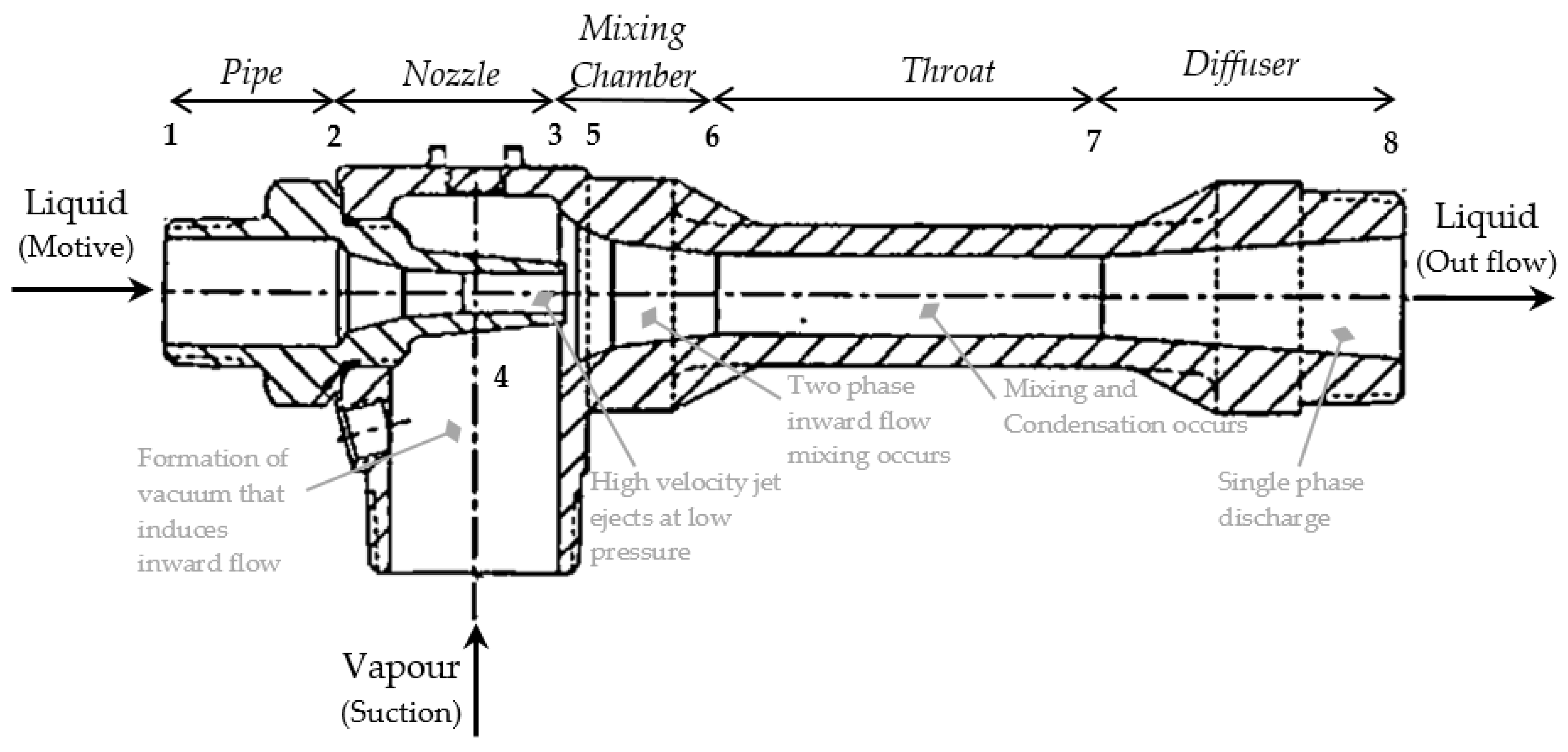
Figure 1. Problem driven opportunity for water treatment [5,6,7,8,9].
Fluids 06 00409 g001
Figure 2. Components in simple ejectors.
Fluids 06 00409 g002
Figure 4. Commercial products available on the market [41,42,43,44,45,46].
Fluids 06 00409 g004
Figure 5. Ejector performance curve.
Fluids 06 00409 g005
Figure 6. Entrainment ratio vs. back pressure for the ejector (source [55]).
Fluids 06 00409 g006
Figure 7. Performance curve of an ejector for designed and operating pressures, 6 bar and 8 bar (source [57]).
Fluids 06 00409 g007
Figure 8. Effect of primary nozzle throat diameter on entrainment ratio [58].
Fluids 06 00409 g008
Figure 9. Entrainment ratio vs. back pressure for different nozzle geometries [59].
Fluids 06 00409 g009
Figure 10. Performance with different nozzle structure at condensing temperature of 30 °C [62].
Fluids 06 00409 g010
Figure 11. (a) are the velocity contour plots for oscillation at 5 Hz frequency at 2° and 10° angles, with inlet, suction and outlet pressure boundary conditions as 4.5 bar, 1 bar and 1 bar, respectively. It shows that velocity waves transport along with the axial plane of the system. (b) the plot for varying frequency at different oscillation angles. Experimental observation of performance for different nozzle positioning [64].
Fluids 06 00409 g011
Figure 12. Geometry considered for this study [65].
Fluids 06 00409 g012
Figure 13. (a,b) Velocity contours at different oscillation angles with 5 Hz frequency (c) ER plot at different frequency and oscillation angles (source [66]).
Fluids 06 00409 g013
Figure 14. Schematic test setup with swirling vanes for water and stem nozzle [68].
Fluids 06 00409 g014
Figure 15. Swirl generator of Banu et al. [69,70].
Fluids 06 00409 g015
Figure 16. Swirl generator design, its intensity and effect on flow passing jet [71].
Fluids 06 00409 g016
Figure 17. Swirl vanes proposed by Chlappetta et al. [73].
Fluids 06 00409 g017
Figure 18. Free spinning pressure exchange device in ejector by Garris et al. [74].
Fluids 06 00409 g018
Figure 19. Mach number contour for varying throat length [79].
Fluids 06 00409 g019
Figure 20. Schematic diagram of two-throat nozzle ejector with throat CSA (mm2) [81].
Fluids 06 00409 g020
Figure 21. Different kinds of nozzle being studied and respective performance [83].
Fluids 06 00409 g021
Figure 22. Velocity of water at 30° angle [84].
Fluids 06 00409 g022
Figure 23. Schematic view of the steam injector SN—steam nozzle, WN—water nozzle, MC—mixing chamber, DF—diffuser, t—mixing chamber throat, CW—condensation wave [85].
Fluids 06 00409 g023
Figure 24. Modes of decomposition of water jets in atmosphere [86].
Fluids 06 00409 g024
Figure 25. Downstream pressure distribution in Venturi system [88].
Fluids 06 00409 g025
Figure 26. Flow channel and points of study of steam jet ejector [89].
Fluids 06 00409 g026
Figure 27. Two phase mixing and condensation phenomena with increasing back pressure [89].
Fluids 06 00409 g027
Figure 28. Condensation of steam in central steam jet-water ejector [91].
Fluids 06 00409 g028
Figure 29. Axial static pressure along the wall of the ejector [92].
Fluids 06 00409 g029
Figure 30. Simplified setup for condensation modelling [93].
Fluids 06 00409 g030
Figure 31. Pressure pulsation frequency at different operating conditions [94].
Fluids 06 00409 g031
Figure 32. (a) Schematic diagram of the experimental setup. (b) Instantaneous flow patterns of the scalar field in the mixing regime at a time interval of 1 s [95].
Fluids 06 00409 g032
Figure 33. Proposed layout of ejector-based vacuum membrane distillation desalination process.
Fluids 06 00409 g033
Figure 34. Numerical model algorithm of ejector based VMD.
Fluids 06 00409 g034
Publisher’s Note: MDPI stays neutral with regard to jurisdictional claims in published maps and institutional affiliations.