Abstract
An Eulerian method to numerically solve incompressible bifluid problems with high density ratio is presented. This method can be considered as an improvement of the Ghost Fluid method, with the specificity of a sharp second-order numerical scheme for the spatial resolution of the discontinuous elliptic problem for the pressure. The Navier–Stokes equations are integrated in time with a fractional step method based on the Chorin scheme and discretized in space on a Cartesian mesh. The bifluid interface is implicitly represented using a level-set function. The advantage of this method is its simplicity to implement in a standard monofluid Navier–Stokes solver while being more accurate and conservative than other simple classical bifluid methods. The numerical tests highlight the improvements obtained with this sharp method compared to the reference standard first-order methods.
1. Introduction
Bifluid problems are ubiquitous in nature and in many industrial applications such as combustion in engines, water waves energy converters, and jet printers to cite only a few. In such applications, the density ratio between the two fluids can be large, for instance the ratio is equal to 1000 between water and air. Accurate numerical modeling and numerical simulations of these kind of phenomena are then necessary, in particular to optimize such devices.
In this paper we are thus concerned with the numerical modeling of incompressible bifluid flows with large density ratios, like air and water, and by the accurate description of the phenomena occurring at their interface. We present a sharp Cartesian method for the simulation of incompressible flows with high density and viscosity ratios. This method is an extension of the second-order Cartesian method for elliptic problems with immersed interfaces developed in [1].
Cartesian grids are an attractive alternative to body fitted meshes. Indeed, they avoid complex mesh generation as well as mesh adaptation when unsteady interfaces are considered. Moreover, the numerical resolution of the governing equations can be simplified with an easy parallelization and the use of standard linear algebra libraries. Generally speaking, numerical schemes are easy to implement on a Cartesian mesh because a dimensional splitting is often possible; however, some numerical modeling is necessary near a complex interface that does not fit the background Cartesian grid. This is the case for fluid structure interface and moreover for bifluid interface where the properties of the flow are discontinuous. Indeed, applying naively a numerical scheme originally devised for a flow with constant or continuously varying density will lead to a non-consistent treatment of the interface. Most of the time, it will result in severe stability issues if the density ratio is large as highlighted in [2] and references therein; therefore, as already mentioned, one has to devise specific numerical schemes at the vicinity of the interface. This region is called narrow band and is the set of numerical points that have at least one neighbor on the other side of the interface.
Conservative or non-conservative approaches can both be used to face this issue. Among the non-conservative approaches, one solution is to regularize the properties of the fluids in the vicinity of the interface, so that the density, viscosity, and their derivatives are continuous in the whole computational domain. This idea leads to the well-known "Continuous Surface Force" (CSF) method [3], where the discontinuous quantities are smoothed near the interface, and in case of a fluid with surface tension, this surface tension is taken into account as a smooth volume force instead of a surface force. This method is widely used (see for instance [4,5]) because it offers a straightforward way to implement the presence of two fluids in an already existing monofluid Navier–Stokes code. However, the exact way that the regularization should be performed is not always clear, and spurious oscillations at the bifluid interface can appear due to errors in the pressure gradient computations. Another non-conservative method introduced by Kang, Fedkiw, and Liu [6] after the CSF is the Ghost Fluid Method (GFM). It is based on a first-order method developed in [7] to solve an immersed interface elliptic problem, with a dimensional splitting making the method easy to implement. The resulting linear system is symmetric and has the same structure as the usual matrix to discretize a Poisson equation with variable coefficient on a Cartesian grid. This method has been used successfully in a lot of works, for instance [8,9]. One drawback is that the method is only first-order accurate near the interface [2] and a loss of conservativity of the momentum of each fluid near the interface can occur leading to erroneous velocities.
Non-conservative methods are often associated with a level-set representation of the interface [4] because the level-set method is itself intrinsically non-conservative at the discrete level, and convenient to use on a Cartesian grid.
The other family of methods is based on the conservative form of the Navier–Stokes equations, where mass and momentum fluxes of each fluid are explicitly computed, see for instance [2,10,11,12,13]. An explicit interface representation is necessary even if the interface do not coincide with grid points. Conservative methods are generally more stable than non-conservative methods. The price for this increased stability is an additional amount of numerical developments due to the interface reconstruction, which can be performed from information carried by Lagrangian markers or by cell quantities such as volume fractions.
Another approach has been developed recently [14,15] to deal with large density ratio. In this approach, a fully second-order method is obtained at the interface (for both velocity and pressure) with several physical boundary treatments, including velocity and traction boundary conditions.
In this paper we aim to preserve as much as possible the simplicity of the Ghost Fluid method of [6], avoiding an explicit identification of the volume fractions near the interface, while improving the accuracy and stability of the pressure computation. We thus propose a method, mainly based on the improvement of the Ghost Fluid method, where the discontinuities across the interface are taken into account in a sharp way with a second-order scheme inspired from [1]. This second-order treatment improves the conservativity of the method, as it will be proved numerically in the section devoted to numerical validations.
After having described the governing equations for the incompressible bifluid flows that we consider (Section 2), the discretization of these equations in each fluid and at the interface are presented (Section 3 and Section 4). The second-order numerical resolution of the elliptic problem arising from the computation of the pressure is introduced (Section 5), and the overall is validated on several two-dimensional numerical test cases (Section 6).
2. Governing Equations
2.1. Flow Equations
We consider a rectangular domain filled with two viscous incompressible fluids with different densities and viscosities. The subdomains and corresponding to the two fluids are separated by an interface as depicted in Figure 1.
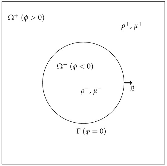
Figure 1.
Sketch of the computational domain.
In this work, these domains are implicitly defined with a scalar function , usually called the level-set function, see Section 2.2, that takes different values in each subdomain with a fixed value on the interface. For instance we chose on , in and in . The unit normal to the interface is denoted and the unit tangent vector is denoted . The density is denoted
and the viscosity is denoted
where H is the Heavyside function, i.e., if and if . Finally, the two-dimensional velocity vector is denoted .
The flow is modeled in the whole domain with the incompressible Navier–Stokes equations:
with the gravitational acceleration vector, the viscous stress tensor:
and the term accounting for the surface tension effects, with the surface tension itself and the local curvature of the interface between the fluids. This formulation of the bifluid incompressible Navier–Stokes equations contains a singular term which is not trivial to handle.
Alternatively, the flow can also be modeled in each subdomain with the incompressible Navier–Stokes equations:
The above equations are completed by jump conditions at the interface between the two fluids. In what follows, jumps are defined by the notation . The first jump conditions describe the balance between the normal stresses at the interface and the surface tension , with the local curvature of the interface ,
Others jump conditions can be derived from continuity properties across the interface. For instance, for a viscous fluid, the velocity field is continuous across the interface
The jump condition for the pressure p can be simplified. We differentiate the jump on the velocity in the tangential direction:
Moreover, because the velocity is divergent-free on each side of the interface,
Combining the two last relationships, we obtain
Consequently
2.2. Interface Description
The interface between the two fluid subdomains is implicitly defined by a scalar function . Local geometrical information on the function is needed to obtain an accurate discretization of the interface. To this purpose we use the level set method, introduced by Osher and Sethian [16] and described in [17,18,19]. A common choice for the level-set function is the signed distance function to the interface:
The zero isoline of thus represents implicitly the interface immersed in the computational domain.
We assume that the interface is smooth enough, so that the derivatives of the level-set function in the vicinity of the interface are well-defined. A useful property of the level-set function is a straightforward computation of its normal with the formula
In the same way, the curvature of the interface can be computed with the formula
We impose a curvature threshold , with h the grid spacing, corresponding to the minimum size of a bubble for a given spatial discretization.
For a moving interface as it is usually the case for bifluid problems, the flow density and viscosity are updated with tracking the interface thanks to the transport equation
where the velocity fields coincides with the flow velocity field on the interface . Different choices for the value of in and can be a priori used. A natural choice we have considered is in the whole domain:
Another possible choice is the extension velocity introduced in [20].
5. Numerical Resolution of Elliptic Problems with Immersed Interfaces
The elliptic problem with discontinuous values across an interface (28)–(30) is solved with the second-order method developed in [1]. The interface points are used to impose the jump conditions across the interface in the numerical scheme. Since the pressure is discontinuous across the interface, two unknowns are created, one for each side of the interface. The accuracy of this method is based on the use of unknowns located at the interface. The size of this linear system is thus augmented with two unknowns for each interface point. These interface unknowns are used to discretize the flux jump conditions and the elliptic operator accurately enough to get a second-order convergence in maximum norm. Actually, to this purpose, near the interface the elliptic operator needs to be discretized with a first-order truncation error, and the fluxes with a second-order truncation error. For a visual explanation of the discretization we refer to Figure 4. The advantage of using this method, compared to the reference work of [6] is that the jump conditions in the correction step are solved with second-order accuracy instead of first-order. The drawback is that the linear system is not symmetric anymore and it is solved with the preconditioned GMRES method.
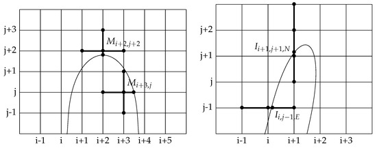
Figure 4.
Left: points involved in the discretization of the elliptic operator at grid nodes and in black, right: Example of stencils for the discretization of jump conditions. Points involved in the discretization of the x-derivative of the pressure at interface point and of the y-derivative of the pressure at interface point in black. For both derivatives are expressed with second-order accuracy while for the left derivative is expressed with second-order and the right derivative with first-order accuracy.
5.1. Discrete Elliptic Operator
We use a standard five-point stencil including the grid point and its nearest neighbors in each direction: interface or grid points. More precisely, we denote the value of the solution on the nearest point in the south direction, with coordinates . Similarly, we define , , and and the associated coordinates , , and . Since the density is piecewise constant, the discretization reads
where stands for or .
5.2. Discrete Flux Transmission Conditions
As written before, at each interface point we create two additional unknowns, called interface unknowns. We denote them by with or S. The interface unknowns carry the values of pressure on each side of the interface.
Contrarily to [1], we do not have a jump condition on the normal derivative, but on the whole gradient, as expressed in formula (30). To obtain the same number of equations and unknowns we have to chose in which direction we want to project this gradient equality. As we use a Cartesian grid, it is easier to discretize the and derivatives than derivatives in other directions. Consequently, we discretize the following jump conditions at each interface point , with .
We want the truncation error of the discretization of flux equality (34) and (35) to be second-order accurate in order to solve the problem with a second-order accuracy. A possible configuration of the interface is illustrated in Figure 4. In the x-direction, it is straightforward to compute a second-order approximation of the x-derivative with three a priori nonequidistant points. For example we approximate the flux on the left side of interface point , if it exists, with the values of p on the points , and with the formula:
The right x-derivative is approximated in the same way.
The same discretization holds for the y-derivative. The formulas (36) and (37) are consistent if both grid points involved in the formula, for instance and , belong to the same domain. If on one side of the interface the two closest grid points aligned with the intersection point do not belong to the same subdomain, then the second-order discretization is not possible anymore. In this case, we use a first-order discretization involving only two points: the interface point and the closest grid point on the same side of the interface. Such a case is illustrated on Figure 4. In fact, this first-order discretization is equivalent to the Ghost Fluid method [6].
Let us notice that, because we use a dimensional splitting for the jump conditions across the interface, it is quite straightforward to eliminate the interface unknowns from the linear system. We simply inject expressions (36) and (37) in the jump condition (34), and use the resulting equality to express as a function of , , and . This expression for can then be used in the discretization of the elliptic operator (32).
The local curvature at the interface point is computed in the following way. We first compute on all irregular grid points the value
with centered second-order finite-difference formulas. Then we perform a one-dimensional linear interpolation of these values on the interface points.
6. Numerical Results and Validations
This section is devoted to the numerical simulations and validations.
After having studied the well-balanced behavior of the proposed approach, i.e., the capacity of the method to preserve equilibria state for a bubble, in Section 6.1, we perform a quantitative validation for the well-known dam break problem from Section 6.2. We then present other numerical simulations for the rising of bubbles with different sizes that can qualitatively been compared to some reference results in Section 6.3.
6.1. Equilibria Preservation for a Bubble: The Parasitic Oscillations
This first test case aims to assess the influence of the interface curvature error on the stability of the numerical scheme. A bubble is located at the center of the computational domain in Section 6.1.1 and Section 6.1.2. Due to the Laplace law and the concavity of the interface, the pressure inside the bubble is larger than the pressure outside. If the curvature of the interface is computed numerically, the errors due to the numerical approximation in the right-hand side of Equation (33) cause small errors in the resolution of the pressure equation and the system is thus not well balanced. These errors create artificial values of the velocity near the interface which should theoretically be zero. These artificial velocities are often called parasitic currents. The amplitude of the parasitic currents is an indication of the stability and the accuracy of the numerical method, and especially of the pressure computational step. Indeed, they are the only source of numerical errors.
In what follows several comparisons with other references methods, the Ghost Fluid and the CSF methods in Section 6.1.1 and the Volume of Fluid method in Section 6.1.2, are presented on slightly different test cases.
6.1.1. Comparison with the Ghost Fluid and the CSF Methods
We use the same parameters as in [8], where a Ghost Fluid and a CSF method were implemented. The amplitude of the parasitic currents, compared to the results in [8], are reported in Table 1. The and norms are computed over the whole domain . The initial configuration is described in Figure 5. As it can be observed, the amplitude of the parasitic currents generated by our method is several orders of magnitude smaller than those of the CSF method, and significantly lower than those of the Ghost Fluid method when the grid is refined.

Table 1.
Comparison between the new method and the numerical results obtained in [8] for the Ghost Fluid method and the CSF method for parasitic oscillations, at time .
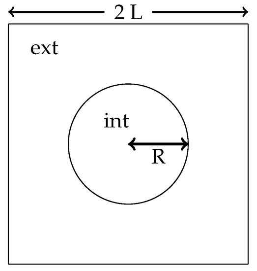
Figure 5.
Test case of the static bubble with parasitic oscillations.
6.1.2. Comparison with a Volume of Fluid Method
We now compare the behavior of our method to the Volume of Fluid method developed in [12]. The density and viscosity ratio are both chosen to be one for this test case. The coefficient is chosen so as to obtain an Ohnesorge number satisfying . The maximum velocity is computed for varying grids at non-dimensional time , with .
A comparison between our method and the Volume of Fluid method is presented in Table 2. The new method provides a better accuracy than the Volume of Fluid method for the coarsest grid. As expected, the Volume of Fluid method outperforms our new approach for finer meshes due to more sophisticated schemes near the interface. Nonetheless, Table 2 show a second-order accuracy for our new method.

Table 2.
Numerical results for parasitic oscillations at non-dimensional time for [12] and our method.
6.2. Collapse of a Water Column: The Dam Break Problem
This test case is studied in [2,34], and based on experiments conducted in [35]. The initial configuration is a water column at rest in air. The initial height and width of the column are both 5.715 cm. The domain size is 40 cm × 10 cm. The physical constants are the same than for the rising bubble (Section 6.1.1). For more details, we refer the reader to [2]. We present in Figure 6 the interface evolution at non-dimensional times , with H the initial height of the water column. The computations are performed with points.
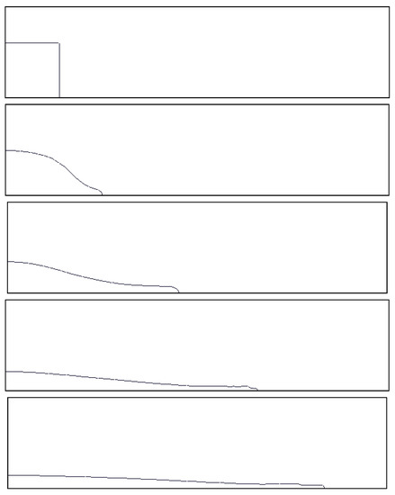
Figure 6.
Evolution of the interface for the dam break problem at non-dimensional times .
Figure 7 present the temporal evolution of the water front, compared to the experimental results [35], to results with the Ghost Fluid method used for pressure resolution, and to the conservative method of Raessi and Pitsch [2]. We observe that the front propagation is in agreement with the experimental results and the results of the conservative method [2]. This means that, though the method is not strictly conservative, the numerical errors due to momentum transfer across the interface are not large enough to slow down the propagation of the front. It is not the case for instance for the Ghost Fluid method, as it can be noticed in Figure 7 and has been reported in [2].
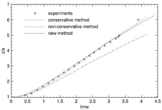
Figure 7.
Evolution of the front of propagation: comparison between experimental data and several numerical methods: the Ghost Fluid method (non-conservative method), the conservative method of Raessi and Pitsch and our new method, The dimensionless location of the front is plotted as a function of the dimensionless time .
6.3. Rising of Air Bubble in Water
We study the evolution of fluid bubbles rising in an heavier fluid, and compare our results to several methods in the literature. The initial configuration is described in Figure 8.
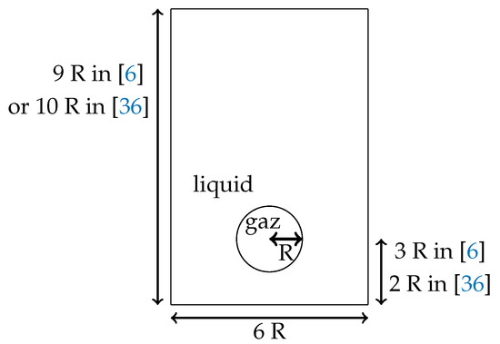
Figure 8.
Initial fluid domain for the test case of the rising bubble in water in the References [6,36].
6.3.1. Comparison with the Ghost Fluid Method
We consider air bubbles rising in water, as in the test case proposed for the Ghost Fluid method in [6]. The value of the physical parameters are
We consider two cases: a small bubble with m and a large one m. In the first case, the surface tension plays an important role in the evolution of the interface because of the high bubble curvature. In the second case, the surface tension has less influence, and larger deformations occur. The interface of the small bubble and the vorticity values are plotted at times t= 0, 0.02, 0.035, 0.05 in Figure 9. The interface of the large bubble and the vorticity values are plotted at times t= 0, 0.2, 0.35, 0.5 in Figure 10. Our numerical results are in good agreement with [6].
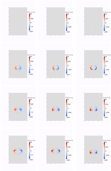
Figure 9.
Evolution of the interface and vorticity values for the small bubble test case, at times 0, 0.02, 0.035, 0.05, resolution: 40 × 60 (left); 80 × 120 (middle); 160 × 240 (right).
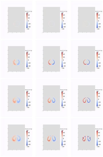
Figure 10.
Evolution of the interface and vorticity values for the large bubble test case, at times 0, 0.2, 0.35, 0.5, resolution: 40 × 60 (left); 80 × 120 (middle); 160 × 240 (right).
6.3.2. Comparison with SPH and the Level-Set Method
This test case is taken from [36], and inspired from a test case presented in [4]. It gives us the opportunity to compare our method to another class of methods, based on the SPH formulation. The initial configuration is described on Figure 8. The values of the physical parameters are
The evolution of the interface and the vorticity values are plotted on Figure 11, for 120 × 200 grid points. We observe that the interface deforms in a way similar to the results in [36].
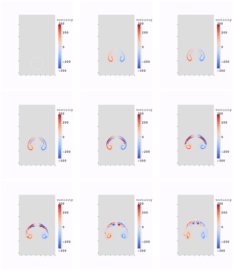
Figure 11.
Evolution of the interface and vorticity values for the bubble test case from [36] at non-dimensional times , resolution 120 × 200.
6.4. Two Air Bubbles in Water
Two air bubble are initially at rest in water, see Figure 12. At the same time that they are rising, their interaction produces larger deformations than for a single bubble. This test case is meant to assessing the conservativity of the new method, as the increase in pression resolution is meant to increase this conservativity.
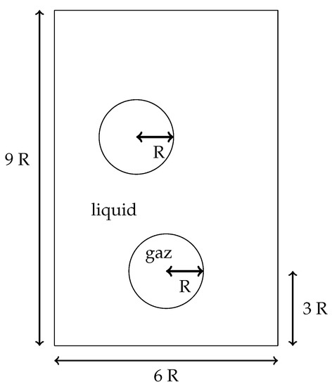
Figure 12.
Initial fluid domain for the test case of the two rising bubbles in water.
The value of the physical parameters are
In Figure 13, the interface evolution and the vorticity values for the Ghost Fluid method (used for the pressure computation) and the new method are plotted. One observes small oscillations of the vorticity near the interface between two fluids for the Ghost Fluid method, but not for the new method. The conservation of the partial mass of air and momentum of air in each dimension for the new method, and the Ghost Fluid method are depicted in Figure 14, Figure 15 and Figure 16 respectively. As air is the less dense fluid, it is more prone to big oscillations if erroneous mass and momentum transfers between the two fluids occur. One can observe that with the new method and its second-order pressure resolution, the oscillations of these quantities are notably less present than for the Ghost Fluid. The partial mass is better conserved too.
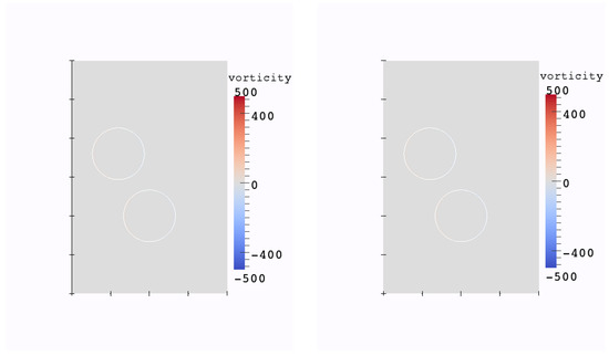
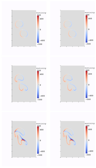
Figure 13.
Evolution of the interface and vorticity values for the two bubbles test case at times , resolution 120 × 180, (left): new method for pressure, (right): Ghost Fluid method for pressure.
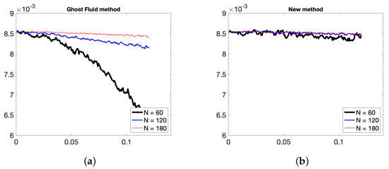
Figure 14.
Evolution in time of partial mass of air with N = 60, 90, 120 points in x-direction with (a) Ghost Fluid method, (b) new method.
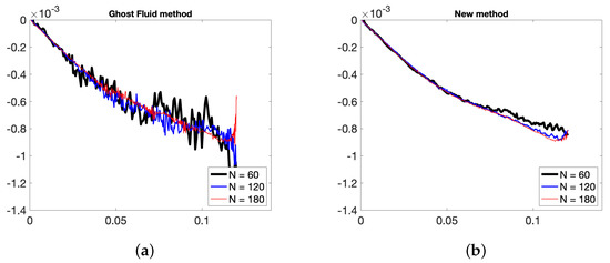
Figure 15.
Evolution in time of partial x-momentum of air N = 60, 90, 120 points in x-direction with (a) Ghost Fluid method, (b) new method.
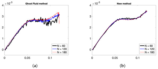
Figure 16.
Evolution in time of partial y-momentum of air N = 60, 90, 120 points in x-direction with (a) Ghost Fluid method, (b) new method.
7. Conclusions
We have developed a new method on Cartesian grids for the simulation of incompressible flows with large density ratios. This method relies on a sharp resolution of the pressure term across the interface defined by a level-set function. The advantage of the proposed approach is its simplicity to implement in an existing Cartesian monofluid Navier–Stokes solver as for instance the Ghost Fluid or CSF methods. It is only necessary to modify the stencil for the pressure equation at some irregular grid points by adding one additional point. This Cartesian scheme uses thus additional unknowns located on the interface to discretize with second-order accuracy the jump conditions across the interface. The viscous term is treated with a regularizing approach that allows us to eliminate terms in the jump conditions. Indeed, it has been shown [32,33] that the regularization has no significant impact on the accuracy of the results. Numerical results show that this method leads to more accurate and stable results than some reference methods as for instance the well known Ghost Fluid or CSF methods. The conservation of volume of each phase is also better conserved. We thus take advantage of both the regularity of the interface defined by the level-set function (curvature is numerically consistent), and the mass conservation of each phase. The CLSVOF [11] can also provide good mass conservation and precision of the interface but with a more complex numerical implementation.
Future works include an extension of the method to three-dimensional problems with interactions with solids including the numerical simulation of wave energy converters [37,38]. We also aim to study the sensibility of the reinitialization procedure of the level-set function defining the bifluid interface, as for instance the one developed in [31].
Author Contributions
M.B. and L.W. both contributed to all aspects: conceptualization, methodology, software, validation, formal analysis, investigation, resources, data curation, writing—original draft preparation, writing—review and editing, visualization, supervision, project administration, funding acquisition. All authors have read and agreed to the published version of the manuscript.
Funding
This study has been carried out with financial support from the French State, managed by the French National Research Agency (ANR) in the frame of the Investments for the future Programme IdEx Bordeaux (ANR-10-IDEX-03-02).
Conflicts of Interest
The authors declare no conflict of interest.
References
- Cisternino, M.; Weynans, L. A parallel second order Cartesian method for elliptic interface problems. Commun. Comput. Phys. 2012, 12, 1562–1587. [Google Scholar] [CrossRef]
- Raessi, M.; Pitsch, H. Consistent mass and momentum transport for simulating incompressible interfacial flows with large density ratios using the level set method. Comput. Fluids 2012, 63, 70–81. [Google Scholar] [CrossRef]
- Brackbill, J.U.; Kothe, D.B.; Zemach, C. A continuum method for modeling surface tension. J. Comput. Phys. 1992, 100, 335–354. [Google Scholar] [CrossRef]
- Sussman, M.; Smereka, P.; Osher, S. A level-set approach for computing solutions to incompressible two-phase flows. J. Comput. Phys. 1994, 114, 146–159. [Google Scholar] [CrossRef]
- Galusinski, C.; Vigneaux, P. On stability condition for bifluid flows with surface tension: Application to microfluidics. J. Comput. Phys. 2008, 227, 6140–6164. [Google Scholar] [CrossRef] [Green Version]
- Kang, M.; Fedkiw, R.P.; Liu, X.D. A Boundary Condition Capturing Method for Multiphase Incompressible Flow. J. Sci. Comput. 2000, 15, 323–360. [Google Scholar] [CrossRef]
- Liu, X.D.; Fedkiw, R.P.; Kang, M. A boundary capturing method for Poisson’s equation on irregular domains. J. Comput. Phys. 2000, 160, 151–178. [Google Scholar] [CrossRef] [Green Version]
- Couderc, F. Développement d’un code de calcul pour la simulation d’écoulements de fluides non miscibles: Application à la désintégration assistée d’un jet liquide par un courant gazeux. Ph.D. Thesis, ENSAE, Toulouse, France, 2007. [Google Scholar]
- Tanguy, S.; Menard, T.; Berlemont, A. A Level Set Method for vaporizing two-phase flows. J. Comput. Phys. 2007, 221, 837–853. [Google Scholar] [CrossRef]
- Rudman, M. A volume-tracking method for computing incompressible multifluid flows with large density variations. Int. J. Numer. Meth. Fluids 1998, 28, 357–378. [Google Scholar] [CrossRef]
- Sussman, M.; Puckett, E.G. A coupled level set and volume of fluid method for computing 3D and axisymmetric incompressible two-phase flows. J. Comput. Phys. 2000, 162, 301–337. [Google Scholar] [CrossRef] [Green Version]
- Sussman, M.; Smith, K.M.; Hussaini, M.Y.; Ohta, M.; Zhi-Wei, R. A sharp interface method for incompressible two-phase flows. J. Comput. Phys. 2007, 221, 469–505. [Google Scholar] [CrossRef]
- Hu, X.; Khoo, B.C.; Adams, N.A.; Huang, F.L. A conservative interface method for compressible flows. J. Comput. Phys. 2006, 219, 553–578. [Google Scholar] [CrossRef]
- Nangia, N.; Griffith, B.E.; Patankar, N.A.; Bhalla, A.P.S. A robust incompressible Navier-Stokes solver for high density ratio multiphase flows. J. Comput. Phys. 2019, 390, 548–594. [Google Scholar] [CrossRef] [Green Version]
- Nangia, N.; Patankar, N.A.; Bhalla, A.P.S. A DLM immersed boundary method based wave-structure interaction solver for high density ratio multiphase flows. J. Comput. Phys. 2019, 398, 108804. [Google Scholar] [CrossRef] [Green Version]
- Osher, S.; Sethian, J.A. Fronts propagating with curvature-dependent speed: Algorithms based on Hamiltonâ Jacobi formulations. J. Comput. Phys. 1988, 79, 12–49. [Google Scholar] [CrossRef] [Green Version]
- Sethian, J.A. Level Set Methods and Fast Marching Methods; Cambridge University Press: Cambridge, UK, 1999. [Google Scholar]
- Sethian, J.A. Evolution, Implementation, and Application of Level Set and Fast Marching Methods for Advancing Fronts. J. Comput. Phys. 2001, 169, 503–555. [Google Scholar] [CrossRef] [Green Version]
- Osher, S.; Fedkiw, R. Level Set Methods and Dynamic Implicit Surfaces; Springer: Berlin/Heidelberg, Germany, 2003. [Google Scholar]
- Adalsteinsson, D.; Sethian, J.A. The Fast Construction of Extension Velocities in Level Set Methods. J. Comput. Phys. 1999, 148, 2–22. [Google Scholar] [CrossRef]
- Rhie, C.; Chow, W. Numerical study of the turbulent flow past an airfoil with trailing edge separation. AIAA J. 1983, 21, 1525–1532. [Google Scholar] [CrossRef]
- Mittal, R.; Dong, H.; Bozkurttas, M.; Najjar, F.; Vargas, A.; von Loebbecke, A. A versatile sharp interface immersed boundary method for incompressible flows with complex boundaries. J. Comput. Phys. 2008, 227, 4825–4852. [Google Scholar] [CrossRef] [Green Version]
- Chorin, A. Numerical solution of the Navier-Stokes equations. Math. Comp. 1968, 22, 745–762. [Google Scholar] [CrossRef]
- Temam, R. Sur l’approximation de la solution des equations de Navier-Stokes par la méthode des pas fractionnaires II. Archiv. Rat. Mech. Anal. 1969, 32, 377–385. [Google Scholar] [CrossRef]
- Sethian, J. A fast marching level set method for monotonically advancing fronts. Appl. Math. 1996, 93, 1591–1595. [Google Scholar] [CrossRef] [Green Version]
- Rouy, E.; Tourin, A. A viscosity solutions approach to shape-from-shading. SIAM J. Numer. Anal. 1992, 29, 867–884. [Google Scholar] [CrossRef]
- Tsai, Y.H.R.; Cheng, L.T.; Osher, S.; Zhao, H.K. Fast sweeping algorithms for a class of Hamilton-Jacobi equations. SIAM J. Numer. Anal. 2003, 41, 673–694. [Google Scholar] [CrossRef]
- Jiang, G.S.; Shu, C.W. Efficient Implementation of Weighted ENO Schemes. J. Comput. Phys 1995, 126, 202–228. [Google Scholar] [CrossRef] [Green Version]
- Russo, G.; Smereka, P. A remark on computing distance functions. J. Comput. Phys. 2000, 163, 51–67. [Google Scholar] [CrossRef] [Green Version]
- duChene, A.; Min, C.; Gibou, F. Second-order accurate computation of curvatures in a level set framework using novel high-order reinitialization schemes. J. Sci. Comput. 2008, 35, 114–131. [Google Scholar] [CrossRef]
- Luddens, F.; Bergmann, M.; Weynans, L. Enablers for high-order level set methods in fluid mechanics. Int. J. Numer. Meth. Fluids 2015, 79, 654–675. [Google Scholar] [CrossRef] [Green Version]
- Desjardins, O.; Pitsch, H. A spectrally refined interface approach for simulating multiphase flows. J. Comput. Phys. 2009, 228, 1658–1677. [Google Scholar] [CrossRef]
- Herrmann, M. The influence of density ratio on the primary atomization of a turbulent jet in crossflow. Proc. Combust. Inst. 2011, 33, 2079–2088. [Google Scholar] [CrossRef]
- Chenadec, V.L.; Pitsch, H. A monotonicity preserving conservative sharp interface flow solver for high density ratio two-phase flows. J. Comput. Phys. 2013, 249, 185–203. [Google Scholar] [CrossRef]
- Martin, J.C.; Moyce, W.J. An experimental study of the collapse of liquid columns on a rigid horizontal plane. Philos. Trans. R. Soc. London, Ser. A 1952, 244, 312–324. [Google Scholar]
- Grenier, N.; Antuono, M.; Colagrossi, A.; Touze, D.L.; Alessandrini, B. An Hamiltonian interface SPH formulation for multi-fluid and free-surface flows. J. Comput. Phys. 2009, 228, 8380–8393. [Google Scholar] [CrossRef]
- Khedkar, K.; Nangia, N.; Thirumalaisamy, R.; Bhalla, A.P.S. The inertial sea wave energy converter (ISWEC) technology: Device-physics, multiphase modeling and simulations. Ocean Eng. 2021, 229, 108879. [Google Scholar] [CrossRef]
- Bhalla, A.P.S.; Nangia, N.; Dafnakis, P.; Bracco, G.; Mattiazzo, G. Simulating water-entry/exit problems using Eulerian–Lagrangian and fully-Eulerian fictitious domain methods within the open-source IBAMR library. Appl. Ocean Res. 2020, 94, 101932. [Google Scholar] [CrossRef]
Publisher’s Note: MDPI stays neutral with regard to jurisdictional claims in published maps and institutional affiliations. |
© 2021 by the authors. Licensee MDPI, Basel, Switzerland. This article is an open access article distributed under the terms and conditions of the Creative Commons Attribution (CC BY) license (https://creativecommons.org/licenses/by/4.0/).
