Article

Mantle Electrical Conductivity and the Magnetic Field at the Core–Mantle Boundary

Department of Physics and Astronomy, George Mason University, Fairfax, VA 22030, USA
Fluids 2021, 6(11), 403; https://doi.org/10.3390/fluids6110403
Submission received: 24 August 2021 / Revised: 21 October 2021 / Accepted: 2 November 2021 / Published: 8 November 2021
(This article belongs to the Special Issue Galactic, Astrophysical and Planetary Dynamos)

Abstract

:
The Earth’s magnetic field is measured on and above the crust, while the turbulent dynamo in the outer core produces magnetic field values at the core–mantle boundary (CMB). The connection between the two sets of values is usually assumed to be independent of the electrical conductivity in the mantle. However, the turbulent magnetofluid in the Earth’s outer core produces a time-varying magnetic field that must induce currents in the lower mantle as it emerges, since the mantle is observed to be electrically conductive. Here, we develop a model to assess the possible effects of mantle electrical conductivity on the magnetic field values at the CMB. This model uses a new method for mapping the geomagnetic field from the Earth’s surface to the CMB. Since numerical and theoretical results suggest that the turbulent magnetic field in the outer core as it approaches the CMB is mostly parallel to this boundary, we assume that this property exists and set the normal component of the model magnetic field to zero at the CMB. This leads to a modification of the Mauersberger–Lowes spectrum at the CMB so that it is no longer flat, i.e., the modified spectrum depends on mantle conductance. We examined several cases in which mantle conductance ranges from low to high in order to gauge how CMB magnetic field strength and mantle ohmic heat generation may vary.

1. Introduction

The geomagnetic field is important as it protects the Earth (and humanity) from the effects of cosmic rays and solar wind. The geomagnetic field is measured on and above the crust but originates in the Earth’s outer core, where a turbulent magnetohydrodynamic (MHD) dynamo exists. These geomagnetic field measurements provide a window through which we can peer into the workings of the outer core. However, this window offers a distorted view because between the Earth’s surface and the outer core lies a thick mantle whose electrical properties affect the transition of the magnetic field from the core to surface. The interface separating the mantle and the outer core is called the core–mantle boundary (CMB). We want to be able to project the geomagnetic field observed on the surface down onto the CMB to provide a clearer picture of the magnetic field directly above the outer core. This, in turn, provides a means to test and further develop various dynamo theories and to enhance our basic knowledge of rotating MHD turbulence.
The geomagnetic field at the surface is usually connected to that on the CMB by ignoring any electrical conductivity in the mantle. However, the mantle is observed to be electrically conductive, as is discussed below. This is critical because the turbulent magnetofluid in the Earth’s outer core produces a time-varying magnetic field that emerges into the mantle to induce electrical currents. The presence of these currents distorts our view of the outer core. Here, we recognized the importance of mantle electrical conductivity and developed a simple yet effective model that allows us to connect the geomagnetic field at the Earth’s surface to that on the CMB.
As stated above, the Earth’s mantle has nonzero electrical conductivity [1,2,3], a property we take into account using the ansatz of [4] to represent the effects of an electrically conducting layer through the presence of a spherical surface current. This leads to a new form for the geomagnetic power spectrum at the core–mantle boundary (CMB). Commensurate with these observations, the mantle, which lies (in a spherical polar coordinate system: r , θ , ϕ ) between the Earth’s surface at r = r e and the CMB at r = r o , is modeled as having an upper insulating part with no electrical current separated at r = r s from an electrically conducting lower part. This lower part, r o r r s , has a spherically symmetric volume of electrical conductivity σ ( r ) , which is taken to be exponential and parametrized by σ s = σ ( r s ) and σ o = σ ( r o ) . The effects of conductivity are modeled by replacing the volume current in the lower mantle by a spherical surface current at a radius r c , where r o < r c < r s , and σ ( r ) by a surface conductance σ c , which is the integral of σ ( r ) over the range r o r r s ; in turn, r c is the integral of r σ ( r ) / σ c over the same range.
This is a classical magnetic boundary value problem. There is a magnetic potential field, i.e., the International Geomagnetic Reference Field (IGRF) [5] for r c < r < , while for r o r < r c , there is another magnetic potential field interior to the mantle and above the CMB. There are two boundary conditions: (i) At the lower mantle current sheet, r = r c , the radial components of the IGRF and interior potential field must match. (ii) At the CMB, the interior potential field is taken to be purely transverse. Boundary condition (ii) is an approximation based on several related factors: numerical results validating the frozen-flux approximation [6], the phenomenon of dynamic alignment [7,8,9,10], and theoretical models in which a spherically confined, turbulent magnetofluid tends to a force-free state [11,12,13] in which the turbulent magnetic field is essentially transverse at the CMB [14].
The end result of this model is a significant modification of the Mauersberger–Lowes (M–L) spectrum [15,16] at the CMB so that it is no longer flat. Magnetofluid turbulence in the core is not expected to have an inertial range [17], so any suitable spectrum should become steeper than the Kolmogorov spectrum k 5 / 3 as the multipole order increases. Here, we discuss how the magnetic spectrum at the CMB is modified for various levels of mantle electrical conductivity and estimate the associated rates of ohmic dissipation.

2. Mathematical Model

2.1. Mantle Conductivity

As mentioned in Section 1, we used a spherical polar coordinate system ( r , θ , ϕ ), where the surface of the Earth is at r e = 6371.2 km, and the mantle lies between r e and the CMB at r o = 3480 km. The insulated upper mantle and electrically conducting lower mantle are separated at r = r s , and the spherical surface current is at r c , with r o < r c < r s . A suitable value for r s and means of finding r c are now discussed.
In order to determine an appropriate value for r s , we consider some recent estimates of mantle conductivity with depth. The estimates of [1,2] have some uncertainty and do not extend completely to the CMB but only to a depth of about 2000 km, while with the more recent results of [3], the estimates extend to a depth of 2900 km. The values for conductivity, when it becomes appreciable in the upper mantle, appear to be similar, though not the depth at which this value ensues. Ref. [1] found that conductivity σ becomes appreciable at a depth of ∼1000 km, while [2,3] found that it becomes appreciable around 650 km deep; at these depths, σ = σ s 4 S/m and seems to increase slightly with depth, but again, the estimates only extend to about 2000 or 2900 km deep. Above the onset of appreciable conductivity, values of σ quickly fall by a factor of ∼ 10 3 , so that the upper mantle r > r s is modeled as nonconducting.
Here, we assume that σ s = 4 S/m at r s = 5371.2 km (1000 km deep); at the CMB, the conductivity is σ o σ s . In the lower mantle, conductivity σ ( r ) is represented as:
σ ( r ) = σ s exp α r s r , r o r < r s ,
α = log σ o / σ s r s r o , σ o = σ ( r o ) .
A similar form of continuous conductivity for a two-layer mantle was used by [18], whereas [19,20] introduced a thin, electrically conducting layer in the mantle above the CMB, which (1) can approximate with large σ o . (Although there may be lateral variation, as noted by [21], we maintain spherical symmetry here).
In addition to the boundary conditions at the CMB, we differ from [18] in that we represent the influence of an electrically conducting lower mantle on the CMB magnetic field by the effect of a spherical surface current located within the lower mantle, an equivalence shown by [4] [Appendix G]. (A similar approach was used by [22], although the current sheet was placed directly on top of the outer core.) Here, surface conductance σ c and current sheet position r c are defined by:
σ c = r o r s σ ( r ) d r = σ o σ s α ,
r c = r o r s r σ ( r ) d r = r o + 1 α 1 σ s σ c ( r s r o ) .
As σ o σ s , we have: σ c ( r s r o ) σ s and r c ( r s + r o ) / 2 . In this model, the parameters σ s and σ o determine the values of σ c and r c . Although we keep σ s at 4 S/m below, various values of σ o are used to examine the effects of possibly increasing conductivity as the CMB is approached.
As previously noted, the presence of a conducting layer in the lower mantle was used before by [19,20] to couple the outer core to the mantle, affecting the relative rotation rates of both. Their conducting layer was 90 km thick, sat on the CMB, and had a conductivity equal to that of the outer core. They integrated radially over this layer to produce a magnetic boundary condition on the CMB. Implicitly, this permitted the magnetic field to transition from the nonpotential outer core field to an exterior potential field. Magnetic boundary conditions are such that the normal component of the magnetic field is continuous, whereas the difference between transverse parts of exterior and interior magnetic fields is related to a current in the conducting layer. In [19,20] and [22], the normal component of the magnetic field appeared very small at the CMB. Here, we assume that the normal, i.e., radial, component can be treated as zero at the CMB through the presence of a conducting layer; through this conducting layer, the radial component grows in its transition to the exterior geomagnetic field. We now proceed to a description of the magnetic fields and derive the electrical current in our model system.

2.2. Exterior Geomagnetic Field

The geomagnetic field B , appropriate for r > r c in our model, is due to a magnetic potential, and is conventionally expressed as
B = r e n = 1 N m = 0 n r e r n + 1 g n m C n m ( θ , ϕ ) + h n m S n m ( θ , ϕ ) .
Henceforth, we denote the double summation symbols above by n , m . g n m and h n m , n = 1 , , 13 , m = 0 , 1 , n are the Gauss coefficients of the IGRF [5], while C n m ( θ , ϕ ) and S n m ( θ , ϕ ) are the cosine harmonics and sine harmonics, respectively:
C n m ( θ , ϕ ) = P ¯ n m ( cos θ ) cos ( m ϕ ) ,
S n m ( θ , ϕ ) = P ¯ n m ( cos θ ) sin ( m ϕ ) .
The associated Legendre functions P ¯ n m ( cos θ ) are Schmidt quasi-normalized [23]. C n m and S n m satisfy the orthogonality relations
C p q S n m θ = 0 π ϕ = 0 2 π C p q S n m sin θ d θ d ϕ = 0 ,
C p q C n m = S p q , S n m = 4 π 2 n + 1 δ p n δ q m .
The Kroenecker delta symbol δ j k = 1 if j = k , and 0 if j k .

2.3. Intermediate Magnetic Field

Between the CMB and the surface current ( r o r < r c ), there is also a magnetic potential field, but of the form
β = r e n , m f n ( r ) G n m C n m ( θ , ϕ ) + H n m S n m ( θ , ϕ ) ,
f n ( r ) = r e r n + 1 + n + 1 n r e r o 2 n + 1 r r e n .
This intermediate field β has r ^ · β = 0 at r = r o in order to match the outer core magnetic field, which is approximated as purely transverse at the CMB.
We now connect g n m and h n m to G n m and H n m and then find the surface current J at r = r c . Since r ^ · ( B β ) = 0 at r = r c , we have
g n m h n m = 1 r c r o 2 n + 1 G n m H n m .
Applying r ^ × ( B β ) = μ o J at r = r c and using Equation (12) yields
J = n , m r e r c n + 2 r × J n m C n m ( θ , ϕ ) + K n m S n m ( θ , ϕ ) ,
J n m K n m = 1 μ o n 2 n + 1 1 r o / r c 2 n + 1 g n m h n m .
We now know the surface current in terms of the Gauss coefficients g n m and h n m of the IGRF.
In terms of the Gauss coefficients, we use (12) to see that the intermediate field β given by (10) at the CMB ( r = r o ) has the form
β = n , m F n r o g n m C n m ( θ , ϕ ) + h n m S n m ( θ , ϕ ) ,
F n ( r o ) = r e r o f n ( r o ) = r e r o n + 2 2 n + 1 n 1 r c r o 2 n + 1 1 .
This intermediate field β is, again, purely transverse at the CMB, i.e., has r ^ · β = 0 at r = r o .

2.4. Power Spectrum of the Geomagnetic Field

The traditional power spectral density R n ( r ) of the geomagnetic field on a spherical surface at radius r is called a Mauersberger–Lowes spectrum [15,16]:
R n ( r ) = ( n + 1 ) r e r 2 n + 4 m = 0 n g n m 2 + h n m 2 .
At the Earth’s surface, it is R n ( r e ) , and at the CMB, it is R n ( r o ) , where the connection between the two is
R n ( r o ) = r e r o 2 n + 4 R n ( r e ) .
Using Equations (9), (10), (12), (16), and (17), we integrate | β | 2 over the surface r = r o on which r ^ · β = 0 . As such, we see that instead of R n ( r o ) at the CMB, we have a spectrum
R n o ( r c ) = n ( n + 1 ) 2 n + 1 F n 2 ( r o ) m = 0 n g n m 2 + h n m 2 = G n ( r c ) R n ( r e ) ,
G n ( r c ) = 2 n + 1 n r c r o 2 n + 1 1 2 r e r o 2 n + 4 .
Note that in the integration that led to (17), in addition to the factor n ( n + 1 ) / ( 2 n + 1 ) given in (19), there is also a factor ( n + 1 ) 2 / ( 2 n + 1 ) due to the nonzero radial part of B ; adding these together produces the factor ( n + 1 ) appearing in (17).
Thus, the results presented here, using the magnetic field β as defined by Equations (15) and (16), suggest that rather than the factor ( r e / r o ) 2 n + 4 appearing in (18), the actual factor depends on the radius r c and takes the form described by (20).
The spectra R n o ( r c ) for the five cases with different σ o and thus r c are compared to the Mauersberger–Lowes spectrum R n ( r o ) at the CMB, as well as the surface spectrum R n ( r e ) in Figure 1. Additionally, a Kolmogorov spectrum k 5 / 3 ¯ is pictured, which takes into account that each multipole n has many associated wavenumbers k [24].
Consider the factor G n ( r c ) : as r c approaches r o , the core magnetic field is expected to continually increase at all n. However, as n becomes large, we have, in terms of the geometric mean r m ,
lim n G n ( r c ) = 2 r e 2 r c r o 2 r m r c 4 n , r m r e r o .
In the limit n , G n ( r c ) (i) proceeds to 0 for r c > r m , (ii) becomes the constant 4 ( r e / r o ) 3 for r c = r m , and (iii) proceeds to for r c < r m . Since r m = 4709 km, r m / r c > 0 for all the r c in Figure 1, and case (iii) applies. However, for all r c , we have
lim n R n o ( r c ) R n ( r o ) = 2 r o r c 4 n + 2 0 .
Thus, the modified spectrum R n o ( r c ) always falls increasingly farther below R n ( r o ) as n increases.
In Figure 1, R n o ( r c ) is pictured for r c = r i , i = 1 , , 5 . Now, r c is a function of σ o through Equation (4) and the definition of σ c in Equation (3); so, for ease of reference, we list their values in Table 1, along with the rms magnitudes of dipole magnetic intensity B D = R 1 c ( r c ) at the CMB, in units of milli-Tesla (mT). In addition, estimates of mantle ohmic heat production rate Q ( r c ) , discussed in Section 2.5 with respect to σ o , are also provided in Table 1.
Let us consider the different cases that appear in Figure 1 and Table 1. The closest r c to the CMB, r 5 , is 236 km above the CMB, and the modified core field at n = 1 is about 200 times the M–L field. For r 1 , which is 945 km above the CMB, the modified core field is about 40 times the M–L field; the other curves fall in between these two. The magnetic power spectrum in the core is not expected to have an inertial range [17], so any suitable spectrum should be steeper than the Kolmogorov spectrum k 5 / 3 . At any value of r c , the magnetic spectra in Figure 1 are close in shape to that shown in Figure 2 in [17], while conductivity close to the CMB only affects their vertical position in Figure 1. The magnetic spectrum of [17] falls by a factor of about 10 4 from n = 1 to n = 10 . The spectra in Figure 1 fall between 3 × 10 5 and about 3 × 10 3 , with the r 3 spectra falling almost exactly by 10 4 . Most of the modified CMB spectra in Figure 1 fall off, as might be expected from the MHD turbulence with a small or nonexistent inertial range, whereas the Mauersberger–Lowes spectrum at the CMB seems much too flat as it only falls by a factor of 10. We chose, somewhat arbitrarily, to compare n = 1 and n = 10 because the IGRF spectrum for n > 10 is not very exact and the n > 10 values have only been included since the year 2000 [5], although earlier work, e.g., [25], estimated that the spectrum was relatively accurate up to n = 13 . Better estimates of mantle electrical conductivity close to the CMB will help determine the value of r c that is most appropriate.
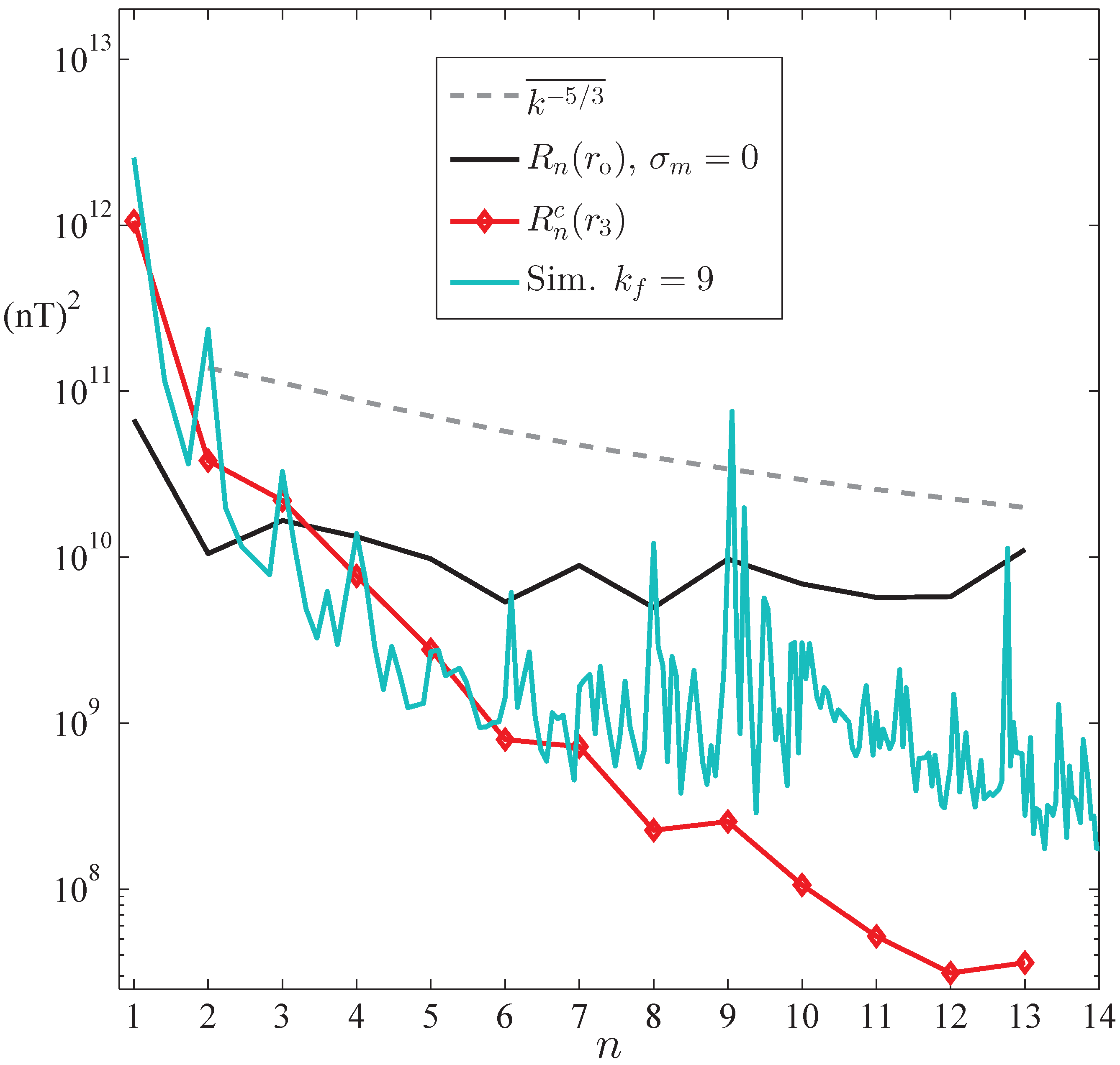
With regard to the magnetic spectra due to magnetohydrodynamic (MHD) turbulence, consider Figure 2, where we use, as an example, the spectrum R n o ( r 3 ) from Figure 1, and then scale and overlay on R n o ( r 3 ) a turbulent spectrum from simulation NM06 in [26]. This simulation was of rotating, dissipative, forced MHD turbulence run on a 64 3 grid for a very long time; the kinetic and magnetic Reynolds numbers were 285 and 200, respectively; the wavenumber range was 1 k < 32 ; and the forcing wave number was k f = 9 , which pushed the spectrum up for k k f . If k f was larger, the simulated spectrum would have had a greater fall-off. This simulation was used to study the low-k behavior of forced, dissipative MHD turbulence and a peak at lowest-k is what is predicted by the statistical theory of ideal MHD turbulence [24,27]. Figure 2 also shows the Mauersberger–Lowes spectrum R n ( r o ) on the CMB and a representative Kolmogorov spectrum k 5 / 3 ¯ . Figure 2 demonstrates that the presence of mantle electrical conductivity is needed to produce a magnetic spectrum on the CMB that is not flat and, at least at low-k, behaves as if it originated out of a turbulent outer core.

2.5. Heat Produced by the Surface Current at r = r c

The current density J on the sphere at r = r c is given by Equation (13); if we integrate, as defined in Equation (8), the squared surface current density J 2 = J · J over the sphere r = r c and divide by the estimated electrical conductance σ c from Equation (3), we arrive at an expression for the heating rate Q ( r c ) = r c 2 J 2 / σ c produced by the surface current J :
Q ( r c ) = 4 π r c 2 μ o 2 σ c n = 1 13 2 n + 1 n R n ( r c ) 1 r o / r c 2 n + 1 2 .
We use SI units in Equation (23), so the Gauss coefficients in R n ( r c ) , described in Equation (17), must be expressed in Tesla and r c in meters, giving Q ( r c ) in terms of watts. Although there is a lack of knowledge as to the actual value of the conductivity as the CMB is approached, a broad range of values for σ o , along with Equation (23), provides a representative range of values for Q ( r c ) .
Again, these estimated heating rates Q ( r c ) are listed in Table 1. The total power produced by the core is estimated to be 10 ± 4 TW [28], so that the values for Q ( r c ) given in Table 1 appear reasonable, decreasing as r c decreases, an effect that is due to the corresponding increase in σ c . These estimates of Q ( r c ) are very approximate, and more realistic values will depend on how σ actually varies with depth, but they provide a qualitative picture of the effects of mantle conductivity.

3. Conclusions

A new method for mapping the IGRF from the Earth’s surface to the CMB was developed and presented here. The proposed mode is not intended to represent the actual conductivity profile in the mantle, which is unknown, but instead to serve as a surrogate that allows the effect of mantle electrical conductivity to be factored into estimating the CMB magnetic field. This led to a modification of the Mauersberger–Lowes magnetic power spectrum at the CMB, by which it may be viewed as no longer flat, but instead falls off in a manner more consistent with a spectrum generated by magnetofluid turbulence.

Funding

This research received no external funding.

Data Availability Statement

Data can be generated from the formulas and the open source IGRF coefficients.

Acknowledgments

This research did not receive any specific grant from funding agencies in the public, commercial, or not-for-profit sectors.

Conflicts of Interest

The author declares no onflict of interest.

References

  1. Civet, F.; Thébault, E.; Verhoeven, O.; Langlais, B.; Saturnino, D. Electrical conductivity of the Earth’s mantle from the first Swarm magnetic field measurements. Geophys. Res. Lett. 2015, 42, 3338–3346. [Google Scholar] [CrossRef]
  2. Grayver, A.V.; Munch, F.D.; Kuvshinov, A.V.; Khan, A.; Sabaka, T.J.; Tøffner-Clausen, L. Joint inversion of satellite-detected tidal and magnetospheric signals constrains electrical conductivity and water content of the upper mantle and transition zone. Geophys. Res. Lett. 2017, 44, 6074–6081. [Google Scholar] [CrossRef] [Green Version]
  3. Velímský, J.; Knopp, O. Lateral variations of electrical conductivity in the lower mantle constrained by Swarm and CryoSat?2 missions. Earth Planets Space 2021, 73, 4. [Google Scholar] [CrossRef]
  4. Kuvshinov, A.; Semenov, A. Global 3-D imaging of mantle electrical conductivity based on inversion of observatory C–responses–I. An approach and its verification. Geophys. J. Int. 2012, 189, 1335–1352. [Google Scholar] [CrossRef] [Green Version]
  5. Thébault, E.; Finlay, C.C.; Beggan, C.D.; Alken, P.; Aubert, J.; Barrois, O.M.; Bertr, F.; Bondar, T.; Boness, A.; Brocco, L.; et al. International Geomagnetic Reference Field: The 13th generation. Earth Planets Space 2021, 73, 49. [Google Scholar] [CrossRef]
  6. Roberts, P.H.; Glatzmaier, G.A. A test of the frozen-flux approximation using a new geodynamo model. Phil. Trans. R. Soc. Lond. A 2000, 358, 1109–1121. [Google Scholar] [CrossRef]
  7. Dahlburg, R.B.; Picone, J.M.; Karpen, J.T. Compressible Dynamic Alignment. In Solar System Plasma Physics; Waite, J.H., Jr., Burch, J.L., Moore, R.L., Eds.; Amer. Geophys. Union: Washington, DC, USA, 1989; Volume 54, pp. 95–98. [Google Scholar]
  8. Mason, J.; Cattaneo, F.; Boldyrev, S. Dynamic Alignment in Driven Magnetohydrodynamic Turbulence. Phys. Rev. Lett. 2006, 97, 255002. [Google Scholar] [CrossRef] [PubMed] [Green Version]
  9. Boldyrev, S. Spectrum of Magnetohydrodynamic Turbulence. Phys. Rev. Lett. 2006, 96, 115002. [Google Scholar] [CrossRef] [PubMed] [Green Version]
  10. Telloni, D.; Perri, S.; Carbone, V.; Bruno, R. Selective Decay and Dynamic Alignment in the MHD Turbulence: The Role of the Rugged Invariants. AIP Conf. Proc. 2016, 1720, 040015. [Google Scholar]
  11. Chandrasekhar, S.; Kendall, C.P. On Force–Free Magnetic Fields. Astrophys. J. 1957, 12, 457–460. [Google Scholar] [CrossRef]
  12. Chandrasekhar, S.; Woltjer, L. On Force—Free Magnetic fields. Proc. Nat. Acad. Sci. USA 1958, 44, 285–289. [Google Scholar] [CrossRef] [Green Version]
  13. Taylor, J.B. Relaxation of toroidal plasma and generation of reverse magnetic fields. Phys. Rev. Lett. 1974, 33, 1139–1141. [Google Scholar] [CrossRef]
  14. Kageyama, A.; Tetsuya, S. Computer simulation of a magnetohydrodynamic dynamo. II. Phys. Plasmas 1995, 2, 1421–1431. [Google Scholar] [CrossRef]
  15. Huguet, L.; Amit, H. Magnetic energy transfer at the top of the Earth’s core. Geophys. J. Int. 2012, 190, 856–870. [Google Scholar] [CrossRef]
  16. Lowes, F. Spatial power spectrum of the main geomagnetic field. Geophys. J. R. Astr. Soc. 1974, 36, 717–730. [Google Scholar] [CrossRef]
  17. Frick, P.G.; Reshetnyak, M.Y.; Sokoloff, D.D. Cascade Models of Turbulence for the Earth’s Liquid Core. Doklady Earth Sci. 2002, 387, 988–991. [Google Scholar]
  18. Ballani, L.; Greiner–Mai, H.; Stromeyer, D. Determining the magnetic field in the core–mantle boundary zone by non–harmonic downward continuation. Geophys. J. Int. 2002, 149, 374–389. [Google Scholar] [CrossRef] [Green Version]
  19. Glatzmaier, G.A.; Roberts, P.H. A three-dimensional self-consistent computer simulation of a geomagnetic field reversal. Nature 1995, 377, 203–209. [Google Scholar] [CrossRef]
  20. Glatzmaier, G.A.; Roberts, P.H. A three-dimensional convective dynamo solution with rotating and finitely conducting inner core and mantle. Phys. Earth Planet. Int. 1995, 91, 63–75. [Google Scholar] [CrossRef]
  21. Yoshino, T.; Kamada, S.; Zhao, C.; Ohtani, E.; Hirao, N. Electrical conductivity model of Al-bearing bridgmanite with implications for the electrical structure of the Earth’s lower mantle. Earth Planet. Sci. Lett. 2016, 434, 208–219. [Google Scholar] [CrossRef]
  22. Bhattacharyya, A. Secular variation of the poloidal magnetic field at the core–mantle boundary. Geophys. J. Int. 1998, 132, 181–190. [Google Scholar] [CrossRef] [Green Version]
  23. Winch, D.E.; Ivers, D.J.; Turner, J.P.R.; Stening, R.J. Geomagnetism and Schmidt quasi-normalization. Geophys. J. Int. 2005, 160, 487–504. [Google Scholar] [CrossRef] [Green Version]
  24. Shebalin, J.V. Broken ergodicity, magnetic helicity, and the MHD dynamo. Geophys. Astrophys. Fluid Dyn. 2013, 107, 353–375. [Google Scholar] [CrossRef]
  25. Langle, R.A.; Estes, R.H. A Geomagnetic Field Spectrum. Geophys. Res. Lett. 1982, 9, 250–253. [Google Scholar] [CrossRef] [Green Version]
  26. Shebalin, J.V. Magnetohydrodynamic turbulence and the geodynamo. Phys. Earth Planet. Inter. 2018, 285, 59–75. [Google Scholar] [CrossRef] [Green Version]
  27. Shebalin, J.V. Magnetic Helicity and the Geodynamo. Fluids 2021, 6, 99. [Google Scholar] [CrossRef]
  28. Nimmo, F. Energetics of the Core. In Treatise on Geophysics 8: Core Dynamics; Olson, P., Ed.; Elsevier: Amsterdam, The Netherlands, 2009; pp. 31–65. [Google Scholar]
Figure 1. The modified CMB magnetic spectrum R n o ( r c ) , for r c = r i , i = 1 , , 5 ; here, in kilometers, r 1 = 4424.8 , r 2 = 4090.7 , r 3 = 3924.5 , r 4 = 3814.7 , and r 5 = 3720.8 ; the geometric mean is r m = r e r o = 4708.7 . For comparison, the Mauersberger–Lowes spectra R n ( r ) at the surface r e = 6371.2 km, and CMB, r o = 3480 km; a Kolmogorov spectrum k 5 / 3 ¯ is also given.
Fluids 06 00403 g001
Figure 2. The spectrum R n o ( r 3 ) from Figure 1 along with a scaled, overlaid turbulent spectrum from simulation NM06 discussed in [26]; NM06 was forced at wavenumber k f = 9 (please see text for more details). The Mauersberger–Lowes spectrum R n ( r o ) on the CMB and a representative Kolmogorov spectrum k 5 / 3 ¯ are also shown.
Fluids 06 00403 g002
Table 1. Model properties for five cases with different σ o . The associated σ c and radii r c = r i , i = 1 , , 5 in Figure 1 are given here, along with estimated values of heating rate Q ( r c ) and rms dipole magnetic intensity B D at the CMB. For comparison, the Mauersberger–Lowes values for B D are 0.0422 mT on the Earth’s surface and 0.259 mT on the CMB. (Conduction in the mantle starts at r s = 5371 km and finishes at the CMB at r o = 3480 km; its effects are modeled as due to a spherical surface current of conductance σ c at r = r c .)
Case, i = 12345
σ o (S/m)440200 10 3 10 4
σ c (kS)7.5629.594.73412414
r c = r i (km)44254091392538153721
B D (mT)0.4240.7171.031.412.01
Q ( r c ) (GW)53.433.720.19.932.72
Publisher’s Note: MDPI stays neutral with regard to jurisdictional claims in published maps and institutional affiliations.