Abstract
The injection of grouts is a consolidation technique suitable for overcoming the structural deterioration of old stone masonry walls. Grouting operations involve introducing a suspension (grout) into a masonry core with the aim of improving the load capacity of the wall, as well as reducing its brittle mechanisms. The yield stress of injection grouts will affect the injection pressure and their flow inside the masonry. However, the determination of some rheological properties such as yield stress in hydraulic grout is challenging, due to the combined effects of hydration reactions and interactions between the particles present in the suspension. In this study, the determination of the yield stress of natural hydraulic lime-based grouts with polypropylene fibers was carried out. The changes in yield stress with time, fibers content and hydration were evaluated by two measurement methods using a rotational rheometer. Additionally, the static and dynamic yield stress as well as the critical shear–strain rate were determined, which provided useful information on the grout design in order to achieve successful grouting operations.
1. Introduction
Ordinary or historical buildings in most european cities until the mid-20th century were built with stone masonry walls. Stone masonry is characterized by a certain vulnerability, mainly due to its irregular morphology and the presence of voids and loose adhesive material, which compromises its structural integrity. The injection of grouts (or grouting) is a consolidation technique to overcome masonry structural deterioration. Indeed, grout injections have been revealed to be an effective method to improve the load capacity of the walls, as well as reducing the brittle mechanisms [1]. Grouting operations involve introducing a suspension (grout) into the masonry core. For proper strengthening with this grouting technique, the compatibility of the new materials with the existing ones as well as good injectability are required. The grout’s injectability appears to be one of the most crucial characteristics in the grouting’s performance. In this context, rheology is used as a tool in the design and quality control of the injection grout [2,3]. Cementitious-based grouts are known for having a complex rheology [4,5], because interaction between the binder particles and grout hydration generates a microstructure that leads to a yield stress that is not constant over time. The yield stress of a grout will affect the relationship between the injection pressure and flow and, therefore, will set the distance that the grout can penetrate in the masonry inner core.
In the literature, some controversy about the existence of yield stress can be found. Some authors say that yield stress is not real and only seems to be present due to limitations in the rheological measurements [4]. On the other hand, others allege that, despite the fact that yield stress does not exist, it makes sense to consider it for practical issues [5,6]. Moreover, several studies show that yield stress in fact exists and, when the suspension is thixotropic, the yield stress strongly depends on a build-up and break-down of the material [7,8,9]. According to Barnes [10], the concept of yield stress has been proved and is still useful in a wide range of applications once it is properly delineated. Another study [11] that dealt with cementitious suspensions defined the yield stress based on two values, which are the static yield stress and dynamic yield stress. The static yield stress is associated with the yield after the suspension leaves the rest, while the dynamic yield stress is linked with the stress required so that the flow continues to occur. However, the reliability in determining yield stress depends on the rheological models used and several factors involved in the measurement apparatus—such as the gap between shearing surfaces, type of geometry and slippage of geometry at low shear–strain rates—which cause the determination of yield stress to be even more complicated [12]. More recently, yield stress has been pointed out as key parameter in the characterization of the pumpability of suspensions like drilling muds [13]. Notwithstanding the relevance of yield stress, no standard procedure is available to determine this parameter; very often, yield stress is used as a single value without considering certain phenomena, such as the thixotropy, the range of the applied shear–strain rate and the hydration of the binder. This work intends to contribute to filling this knowledge gap.
Natural hydraulic lime (NHL) is the most commonly used material for heritage masonry consolidation since it is a binder that provides adequate chemical, physical and mechanical compatibility with the original materials present in the masonry [14]. Nevertheless, one of NHL’s drawbacks is cracking due to drying shrinkage [15]. However, this issue can be overcome by adding fibers [16,17]. Fibers are additions that are frequently incorporated into cementitious materials aiming to increase their mechanical strength and reduce cracking [18,19]. There are various types of fibers that can be used in cementitious materials: natural, metallic, ceramic and polymeric [20]. They may be categorized according to the raw material and they can also be characterized in terms of their length, shape and diameter [17].
Polypropylene (PP) fiber is the most common type of fiber used in cementitious materials, but there are still a very limited number of studies on the effects of PP fiber on lime-based materials [21,22]. For instance, Chan and Bindiganavile [23,24] used it in NHL mortars with a dosage of up to 0.5% by volume. Moreover, Barbero-Barrera and Medina [25] analyzed the effect of PP fibers on graphite-natural hydraulic lime pastes. Besides the improvement of mechanical properties that PP fibers can provide, the rheological properties, especially the yield stress, of grouts containing PP fibers should also be examined for an accurate injection. Within this scope, this work aimed to determine both the static and dynamic yield stress of NHL grouts, including the contribution of thixotropy, time period and PP fibers content, by means of two measurement methods using a rotational rheometer. Additionally, several correlations between yield stress, time and critical shear–strain rate (marking the transition from dynamic to static yield stress) were developed.
2. Materials and Methods
2.1. Materials
The experimental program was conducted using a type of NHL, namely NHL5, produced according to the european Standard eN459-1:2010 [26]. NHL was chosen as the binder, since it is a hydraulic binder that has chemical and physical properties close to those of pre-existing materials in heritage masonries and can set both in dry and wet conditions [11,27]. The physical and chemical properties of NHL are listed in Table 1. The grain size distribution is represented in Figure 1.

Table 1.
Chemical composition and physical property of natural hydraulic lime (NHL5) (provided by the manufacturer).

Figure 1.
Particle size distribution of NHL.
A type of polypropylene (PP) fibers with a density of 0.9 g/cm3 was used. The average diameter and length of the PP fibers were 0.05 and 12 mm, respectively. To improve grout’s injectability, especially at a low water/binder ratio, superplasticizers are frequently used [28,29]. In this study, a commercially available polycarboxylate powder superplasticizer (i.e., high range water reducer) conforming to ASTM C494-05 [30] was used. It had a specific gravity, pH, and chloride content of 0.6, 4.2 and <0.1%, respectively.
2.2. Mixture Proportions and Procedure
In this study, all the grouts were based on a water-to-binder (w/b) ratio of 0.4 and the dosage of superplasticizer was set at 0.2% of the mass of NHL. Both the w/b ratio and superplasticizer dosage were chosen according to their typical usage in field applications [31]. The volume fractions of PP fibers by NHL mass were selected as 0%, 0.03% and 0.1%. The mix proportions of grouts are listed in Table 2.
Table 2.
Proportions of grouts used in this study.
All the grouts were prepared in laboratory in batches of 300 mL and mixed using a high shear mixer equipped with a helicoidal blade. The NHL and superplasticizer were first added into the mixer and dry-mixed at a low speed for 2 min, and the PP fibers were gradually introduced at the same time. Afterwards, water was added into the mixer and mixed at a high speed for 3 min. The grouts were prepared at an ambient temperature of 20 ± 2 °C and a relative humidity of 60% ± 5%. Following the completion of mixing, the rheological measurements were performed as described below.
2.3. Experimental Procedures
The rheological measurements were performed with a Bohlin Gemini HRnano rotational rheometer (Malvern Instruments). Parallel-plate geometry was used to perform all the measurements. The diameter of the geometry was 40 mm and the gap was 2 mm. The surface roughness of the upper plate was modified by means of an emery paper (grid 120) to minimize slippage during the measurements.
Rotational measurements with controlled shear rate (CSR) were performed. The measurements were made in the shear rate range of 0.5–300 s−1 followed by a downwards curve in order to evaluate the existence of thixotropy. It should be highlighted that the shear–strain rate range tested corresponded to the typical shear rate range during the grout injection process in order to reveal representative rheological parameters. This shear–strain rate range was associated with the pressures usually adopted during the consolidation of old masonries, which must be below 0.5–1 bar in order to not cause instability of the masonry [28].
A common approach to determine the yield stress is fitting a yield-stress-containing model to shear stress vs. shear–strain rate data. Over the years, useful progress has been made in applied rheology and different rheological models have been suggested [32,33,34,35,36,37,38]. The most popular rheological models that have been proposed to describe suspensions with yield stress are the Bingham, Casson and Herschel–Bulkley [3,35,36,37]. However, there is no single model that can adequately describe the behavior of all complex suspensions, in addition to the fact that none of these models have a limit on the maximum shear stress. Most models assume that the shear stress increases infinitely with the shear–strain rate, which does not reflect reality, since any fluid has a maximum shear stress value. To overcome this limitation, Vipulanandan and Mohammed [13] proposed a hyperbolic model that has been successfully used in the characterization of drilling muds [33,34]. However, for the materials used in this study and for the range of shear–strain rates experienced (i.e., below the maximum shear stress of the grout due to structural safety requirements of masonry) the Herschel–Bulkley proved to be the model that best described the behavior of NHL-based grouts, corroborating what has been concluded in previous studies [36,37]. The Herschel–Bulkley model is able to predict the yield stress at low shear rates and determine the shear-thinning behavior of cementitious suspensions [37]. Thus, the experimental data (shear stress vs. shear–strain rate) were adjusted to the Herschel–Bulkley equation (see Equation (1)) to calculate the yield stress.
where is yield stress (Pa), k is the correlation parameter (Pa.sn), is the shear–strain rate (s−1) and n is the flow index (-), which describes shear thinning (n < 1) and shear thickening behavior (n > 1).
Moreover, controlled shear stress (CSS) was adopted to carry out the stress ramp tests. The stress was increased from 0.006 to 140 Pa and followed by a down ramp with a linear ramp of 0.3 Pa/s. The subsequent apparent viscosity and shear rate were measured for 50 min. It is known that, when a grout exceeds the yield stress, an abrupt and profound change in their microstructure is observed, leading to a state of less resistance. This microstructure change can be graphically portrayed in plots of apparent viscosity against shear stress, where it is possible to verify that below a critical shear stress the fluid in question appeared to have an infinite viscosity, and above the critical stress a shear-thinning behavior. All the rheological measurements were carried out with a constant temperature of 20 °C, maintained by means of a temperature unit control. A solvent trap was used to prevent drying of the grout samples during testing.
3. Results and Discussion
3.1. Thixotropy and Yield Stress by CSR Method
In general, a yield stress fluid does not depend on shear history and a linear proportionality between the shear stress and the shear–strain rate can be established. However, although the NHL-based grout exhibits yield stress, its behavior is time-dependent and a non-linear relationship between the shear stress and shear–strain rate is often observed [2,11]. Considering these statements, a series of controlled shear–strain rate measurements was carried out on the same sample for 50 min with 10 min intervals between each measurement. This is shown in Figure 2 for the case of the grout without PP fibers.
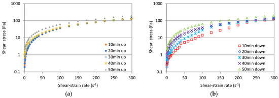
Figure 2.
Shear stress curves of the reference grout: (a) up curve, (b) down curve.
From Figure 2, it can be seen that the shear stress constantly increases with time, which is a consequence of the hydration process of NHL. Additionally, the characteristic behavior of a thixotropy material, in which the up curve has higher shear stresses values than the down curve, can also be noted. Nevertheless, the thixotropy tends to become less pronounced over time, which can be associated with the formation of hydration products that are not destroyed by the application of the shear–strain rate [38,39]. In Figure 3 and Figure 4, the results for the grouts with PP fibers are represented. As expected, the PP fibers had an influence on the rheological curves of fresh grouts by increasing their shear-thinning behavior [40]. It can be noted that the addition of the PP fibers increased the measured shear stress of grouts, especially for the dosage of 0.1%, at low shear–strain rates (see Figure 4).
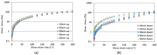
Figure 3.
Shear stress curves of grout with 0.03% polypropylene (PP) fibers: (a) up curve, (b) down curve.
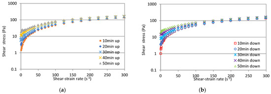
Figure 4.
Shear stress curves of grout with 0.1% PP fibers: (a) up curve, (b) down curve.
The increase in shear stress and the consequent loss of workability resulting from the increase in fiber content was also obtained in studies by Banfill et al. [41] and Tabata-Baeian et al. [42]. This occurs due to mechanical interlocks and bridges between binder particles and fibers. The results show that the effect of thixotropy is less pronounced in the presence of PP fibers and becomes almost non-existent for grouts with a higher fiber dosage, which reflects a nondependent shearing history caused by a high volume of PP fibers. However, as time passes, the thixotropy becomes less evident, as happened with the reference grout. Based on the Herschel–Bulkley model, two yield stresses were calculated, namely the static and dynamic yield stress for the up and down curves, respectively (see Figure 5). Since the samples were resting prior to measurement, the up curve is supposed to provide the static yield stress while the down curve provides the dynamic yield stress [11].
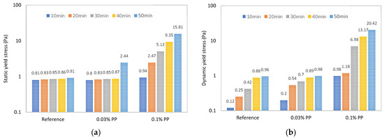
Figure 5.
Effects of PP fibers on yield stress values by controlled shear rate (CSR) measurement: (a) static yield stress, (b) dynamic yield stress.
From Figure 5, it can be observed that the yield stress gradually increases with the addition of PP fibers, which is consistent with References [40,41]. However, there is a greater increase in yield stress values between the dosage of 0.03% and 0.1%. This occurred because the interconnections between the suspension systems were modified by adding PP fibers [37,40]. This means that the fibers fill the gaps between binder particles, which contributes to the formation of a more cohesive microstructure that results in higher yield stress [43]. Notwithstanding, it can be seen from Figure 5b that the dynamic yield stress is lower than the static one for very low contents of PP fibres. On the other hand, for the highest fiber content, it is possible to observe that for time periods above 30 min, the dynamic yield stress is higher than the static one, which may be due to the combined effects of the grout hydration and the very cohesive microstructure.
3.2. Yield Stress by CSS Method
CSS measurements were performed due to their wide-ranging suitability for the determination of yield stress [9,10]. So, as previously described, the grout samples were subjected to a CSS from 0.006 to 140 Pa for the up curve and down curve. As shown in Figure 6, for the grout with 0.03% PP fibers, the change in the apparent viscosity in the up curve before yielding and after yielding is rather sudden; i.e., the apparent viscosity has a high value at low shear stresses and tends to a low constant viscosity value at higher shear stresses.
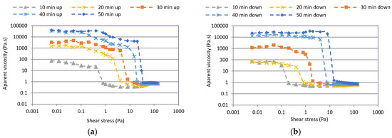
Figure 6.
Curves obtained from the shear stress ramp for grout with 0.03% PP fibers: (a) up curves (b) down curves.
Based on the results presented in Figure 6, it can be noticed that the up curve shows a higher apparent viscosity and yield stress than the down curve due to the thixotropy. The other grout compositions showed an analogous trend. The yield stresses increased with time from 0.4 to 20 Pa. The yield stress increased to 4 Pa after 20 min, and between 20 and 40 min the yield value increased from 4 to 15 Pa. A comparison of the static and dynamic yield stress results for all the grout compositions is shown in Figure 7. As predicted, the static yield stress values are higher compared to the dynamic yield stress. This can be explained by the particle bonds that are broken down due to the shearing from the up ramp, which reduces the dynamic yield stress values. An interesting fact is that, even though both yield stresses increase with the addition of fibers, the yield stresses appear to increase more significantly over time. This can be justified by the hydration reactions of NHL, since during the hydration process a build-up of the microstructure occurs and, consequently, the yield stress increases [38,39].
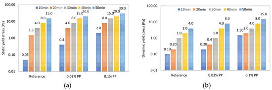
Figure 7.
Effects of PP fibers on yield stress values by controlled shear stress (CSS) measurement: (a) static yield stress, (b) dynamic yield stress.
3.3. Comparison between Yield Stress, Critical Shear–Strain Rate and Time Period
In Figure 8, the yield stress values obtained by the fitting of the Herschel–Bulkley model to the experimental data obtained by CSS and CSR methods are compared. From these results, it can be noted that the yield stress values show just moderate differences between both measurement methods; however, the CSR leads to smaller values than the CSS. There are several reasons for this difference, such as the internal cohesion force of the sample’s microstructure and the sample shear history. However, it is known that measurements taken with CSS often provide better results than measurements with controlled CSR [44]. Nevertheless, the results confirm the efficiency of the Herschel–Bulkley model to determine the yield stress of the NHL grouts, regardless of the measurement method used [45].
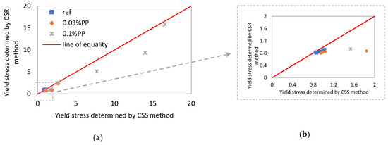
Figure 8.
Comparison of static yield stress modeled by CSS and CSR: (a) all yield stress range; (b) focus on lower yield stress values.
In order to highlight the ability of the different measurement methods to characterize NHL grouts, a comparison between the experimental curves of the CSS and CSR methods at 20 min for the reference grout and the one with 0.03% PP fibers are shown in Figure 9 and Figure 10, respectively (the other time periods and compositions presented similar behavior). Based on the results obtained, it can be seen that regardless of the measurement method performed, the flow curves show similar behavior. However, the addition of PP fibers caused a slight difference between the CSS and CSR curves at high shear–strain rates (see Figure 10).
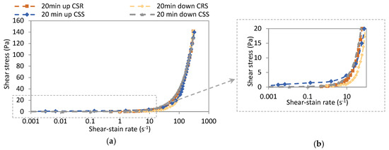
Figure 9.
Flow curve obtained by CSS and CRS methods for the reference grout: (a) all shear-strain rate range; (b) focus on lower shear-strain rates.
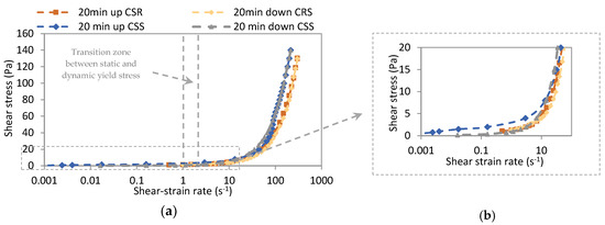
Figure 10.
Flow curve obtained by CSS and CRS methods for grout with 0.03% PP fibers: (a) all shear-strain rate range; (b) focus on lower shear-strain rates.
From the results presented in Figure 10, a slight linear increase in shear stress can be noted until 1 s−1 for both the up and down curves. Moreover, a considerable increase in shear stress can be observed for shear–strain rates above 3 s−1, which explains the change of apparent viscosity presented in Figure 6. Based on these results, it can be seen that the shear–strain rate range of between 1 and 3 s−1 is the transition zone between the two yield stresses, or, in other words, a shear–strain rate of up to 1 s−1 would lead to a static yield stress, while shear–strain rates higher than 3 s−1 would provide a dynamic yield stress. It should be noted, however, that this transition zone between the two different yield stresses is time-dependent, as shown in Table 3.
Table 3.
Evolution of shear–strain rate range for the yield stress transition as a function of time.
By analyzing the results of Table 3, it is possible to conclude that the shear–strain rate, which is necessary for the grout to start to flow or to continue flowing (depending on the case), increases significantly over time. Increases in the critical shear–strain rate of up to 60% and more than 90% between 10–20 min and 10–30 min were found, respectively. This behavior can be seen as a consequence of hydration reactions [46], which can significantly affect the success of the masonry consolidation operation if proper precautions are not taken during the grouting design, such as adjusting the grout’s yield stress to the shear–strain rate range to which the grout will be subjected during injection.
From a practical point of view, the grout is in a broken-down state when it reaches the masonry core in the first moments of the injection operation; however, when the grout is at a distance significantly away from the injection point, the maximum yield stress may be reached due to the reduction of the shear–strain rates. So, as previously highlighted, the yield stress value must be chosen according to the shear–strain rate range of interest. In this sense, a dynamic yield stress should be used at the beginning of the injection operation when the grout is in a fully broken-down state or, in other words, subjected to high shear rates. Meanwhile, static yield stress should be a design parameter only for lower shear–strain rates (i.e., at later stages of the grouting operation) when the links between NHL particles start to take place. This is also effective in situations involving sudden stoppages of the injection process. In order to better illustrate the relationship between time and the shear–strain rate range that causes the transition between static and dynamic yield stress, a regression analysis was made. Shear–strain rate values for all grout compositions were achieved by using the CSS method and measurement instances of 10, 20, 30, 40 and 50 min were considered. As shown in Figure 11, a good correlation was obtained (r2 > 0.9) and two equations were proposed in order to allow the estimation of critical shear–strain rate values based on the time period after the grout mixing process was completed.

Figure 11.
Correlation between the shear-strain rate range and time.
In addition, correlations between yield stresses and shear–strain rates were also established (see Figure 12). Since good correlations between the yield stress values and shear–strain rate were found, several equations were proposed. In this way, the shear–strain rate values could be forecasted by knowing the yield stress values and, therefore, predications of the critical shear–strain rate below which there is a transition fromdynamic to static yield stress could be made. It should be highlighted that the validity domain of the proposed models is limited to a given set of materials and assumptions, so any extrapolations must be done carefully.
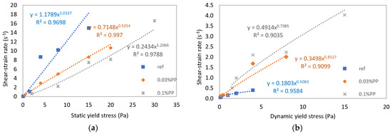
Figure 12.
Correlation between the shear–strain rate range and (a) static yield stress, (b) dynamic yield stress.
The results and measurements performed show that these methods enable the evaluation of the yield stress of NHL-based grouts and the critical shear–strain rate range. In addition, to maximize the injectability of the grout, it is imperative not to stop the grouting operation for a long time (for instance time periods greater than 20 min) in order to prevent the yield stress from increasing. To restart the flow, it is necessary to increase the shear–strain rate or, in other words, increase the injection pressure, which can consequently cause additional damage to the masonry.
4. Conclusions
In this study, the yield stress of NHL-based grouts over a range of time periods and with different polypropylene fiber contents was investigated. The grouts were made with a polycarboxylate powder superplasticizer and PP fibers in amounts of up to 0.1% of PP fiber content (by weight). Yield stress is a key parameter in the design and optimization of grouts for the consolidation of old masonries. Two yield stress values, namely the static and dynamic yield stress, were determined based on different experimental measurement methods. The results obtained allow us to draw the following conclusions:
- The static yield stress values were higher compared to the dynamic yield stress. Differences between both yield stresses were obtained in a range of 33% to 670%, depending on the content of PP fibers. This can be explained by the semi-disturbed state of the grout’s microstructure when the dynamic yield stress was determined, which was mainly due to the shear history dependence of the grout.
- The PP fibers influenced on the rheology of the NHL grouts by increasing their shear-thinning behavior. Moreover, both yield stress values increased with the presence of PP fibers. For example, for the reference grout (without fibers), the minimum and maximum values of the static yield stress varied from 0.05 to 15 Pa, while for the grout with 0.1% PP fibers, the values varied between 2 and 30 Pa. The amount of changes in the yield stress values was due to the structural build up and flocculation, which was a consequence of the mechanical interlocks between the NHL particles and fibers.
- The yield stress values depended on the measuring method. However, the yield values determined by CSS and CSR only showed moderate differences between them, which confirmed the efficiency of the Herschel–Bulkley model in determining the yield stress of NHL grouts whatever the measurement method used.
- The results and measurements performed showed that these methods enable us to evaluate the existence of a critical shear–strain rate range of 0.1 to 17.0 s−1 (depending on time period). Below this, there was a transition between dynamic and static yield stress.
- The dynamic yield stress should be used as design parameter at early stages of the grout injection process, whilst at a later stage, when the shear rate is slowing down, the static yield stress should be considered.
- Several equations that allow the estimation of the critical shear–strain rate as a function of time and yield stress have been proposed in order to promote better design of injection grouts.
- The critical shear–strain rate range increases over time. Therefore, to maximize the injectability of the grout, it is imperative to avoid stopping the grouting operation for periods longer than 20 min.
The findings from this study are relatively promising for further understanding the evolution of yield stress of NHL grouts as a function of time, shear–strain rate and PP fiber content. Furthermore, the results presented contribute helpful information on the design input of grouting operations.
Author Contributions
Conceptualization, L.G.B., F.M.A.H. and M.T.C.; methodology, L.G.B.and M.T.C.; writing—original draft preparation, L.G.B.; writing—review and editing, L.G.B., M.T.C. All authors have read and agreed to the published version of the manuscript.
Funding
This work is funded by National Funds through FCT/MCTeS—Portuguese Foundation for Science and Technology, Reference UID/CTM/50025/2013 and FeDeR funds through the COMPeTe 2020 Programme under the project number POCI-01-0145-FeDeR-007688.
Conflicts of Interest
The authors declare no conflict of interest.
References
- Kalagri, A.; Miltiadou-Fezans, A.; Vintzileou, E. Design and evaluation of hydraulic lime grouts for the strengthening of stone masonry historic structures. Mater. Struct. 2010, 43, 1135–1146. [Google Scholar] [CrossRef]
- Baltazar, L.G.; Henriques, F.M.A.; Cidade, M.T. Rheological characterization of injection grouts using rotational rheometry. In Advances in Rheology Research; Nova Science Publishers: New York, NY, USA, 2017; pp. 13–42. ISBN 978-1-53612-876-5. [Google Scholar]
- Baltazar, L.G.; Henriques, F.M.A.; Cidade, M.T. Rheology of natural hydraulic lime grouts for conservation of stone masonry—Influence of compositional and processing parameters. Fluids 2019, 4, 13. [Google Scholar] [CrossRef]
- Barnes, H.A.; Walters, K. The yield stress myth? Rheol. Acta 1985, 24, 323–326. [Google Scholar] [CrossRef]
- Hartnett, J.P.; Hu, R.Y.Z. Technical note: The yield stress—An engineering reality. J. Rheol. 1989, 33, 671. [Google Scholar] [CrossRef]
- Schurz, J. The yield stress—An empirical reality. Rheol. Acta 1990, 29, 170–171. [Google Scholar] [CrossRef]
- Keentok, M. The measurement of the yield stress of liquids. Rheol. Acta 1982, 21, 325–332. [Google Scholar] [CrossRef]
- Dzuy, N.Q.; Boger, D.V. Yield stress measurement for concentrated suspensions. J. Rheol. 1983, 27, 321. [Google Scholar] [CrossRef]
- Coussot, P.; Nguyen, Q.D.; Huynh, H.T.; Bonn, D. Viscosity bifurcation in thixotropic, yielding fluids. J. Rheol. 2002, 573–589. [Google Scholar] [CrossRef]
- Barnes, H.A. The yield stress—A review or ‘παντα ρει’—Everything flows? J. Non Newton Fluid 1999, 81, 133–178. [Google Scholar] [CrossRef]
- Hakansson, U. Rheology of Fresh Cement-Based Grouts. Ph.D. Thesis, The Royal Institute of Technology, Stockholm, Sweden, 1993. [Google Scholar]
- Al-Martini, S.; Nehdi, M. Effect of chemical admixtures on rheology of cement pastes at high temperature. J. ASTM Int. 2007, 4, 1–17. [Google Scholar] [CrossRef]
- Vipulanandan, C.; Mohammed, A.S. Hyperbolic rheological model with shear stress limit for acrylamide polymer modified bentonite drilling muds. J. Petrol Sci. Eng. 2014, 122, 38–47. [Google Scholar] [CrossRef]
- Collepardi, M. Degradation and restoration of masonry walls of historical buildings. Mater. Struct. 1990, 23, 81–102. [Google Scholar] [CrossRef]
- Pozo-Antonio, J.S. Evolution of mechanical properties and drying shrinkage in lime-based and lime cement-based mortars with pure limestone aggregate. Constr. Build. Mater. 2015, 77, 472–478. [Google Scholar] [CrossRef]
- Puertas, F.; Amat, T.; Fernández-Jiménez, A.; Vázquez, T. Mechanical and durable behaviour of alkaline cement mortars reinforced with polypropylene fibres. Cem. Concr. Res. 2003, 33, 2031–2036. [Google Scholar] [CrossRef]
- Banthia, N.; Gupta, R. Influence of polypropylene fiber geometr on plastic shrinkage cracking in concrete. Cem. Concr. Res. 2006, 36, 1263–1267. [Google Scholar] [CrossRef]
- Noushini, A.; Samali, B.; Vessalas, K. Effect of polyvinyl alcohol (PVA) fibre on dynamic and material properties of fibre reinforced concrete. Constr. Build. Mater. 2013, 49, 374–383. [Google Scholar] [CrossRef]
- Liu, J.; Sun, W.; Miao, C.; Liu, J.; Li, C. Assessment of fiber distribution in steel fiber mortar using image analysis. J. Wuhan Univ. Technol. Mater. Sci. 2012, 27, 166–171. [Google Scholar] [CrossRef]
- Campello, E.; Pereira, M.V.; Darwish, F. The effect of short metallic and polymeric fiber on the fracture behavior of cement mortar. Procedia Mater. Sci. 2014, 3, 1914–1921. [Google Scholar] [CrossRef][Green Version]
- Lucolano, F.; Liguori, B.; Colella, C. Fibre-reinforced lime-based mortars: A possible resource for ancient masonry restoration. Constr. Build. Mater. 2013, 38, 785–789. [Google Scholar] [CrossRef]
- Di Bella, G.; Fiore, V.; Galtieri, G.; Borsellino, C.; Valenza, A. Effect of natural fibers reinforcement in lime plasters (kenaf and sisal vs. polypropylene). Constr. Build. Mater. 2014, 58, 159–165. [Google Scholar] [CrossRef]
- Chan, R.; Bindiganavile, V. Toughness of fibre reinforced hydraulic lime mortar. Part 1: Quasi-static response. Mater. Struct. 2010, 43, 1435–1444. [Google Scholar] [CrossRef]
- Chan, R.; Bindiganavile, V. Toughness of fibre reinforced hydraulic lime mortar. Part 2: Dynamic response. Mater. Struct. 2010, 43, 1445–1455. [Google Scholar] [CrossRef]
- Barbero-Barrera, M.M.; Medin, N.F. The effect of polypropylene fibers on graphite-natural hydraulic lime pastes. Constr. Build. Mater. 2018, 184, 591–601. [Google Scholar] [CrossRef]
- CEN. Building Lime-Part 1: Definitions, Specifications and Conformity Criteria; EN 459-1; CEN, European Committee for Standardization: Brussels, Belgium, 2010. [Google Scholar]
- Binda, L.; Saisi, A.; Tedeschi, C. Compatibility of materials used for repair of masonry buildings: Research and applications. Fracture Failure Nat. Build. Stone 2006, 167–182. [Google Scholar] [CrossRef]
- Jorne, F.; Henriques, F.M.A.; Baltazar, L.G. Influence of superplasticizer, temperature, resting time and injection pressure on hydraulic lime grout injectability. Correlation analysis between fresh grout parameters and grout injectability. J. Build. Eng. 2015, 4, 140–151. [Google Scholar] [CrossRef]
- Baltazar, L.G.; Henriques, F.M.A.; Cidade, M.T. Experimental study and modeling of rheological and mechanical properties of NHL grouts. J. Mater. Civil Eng. 2015, 27. [Google Scholar] [CrossRef]
- ASTM. Standard Specification for Chemical Admixtures for Concrete; ASTM C494; ASTM International: West Conshohocken, PA, USA, 2005. [Google Scholar]
- Baltazar, L.G.; Henriques, F.M.A.; Cidade, M.T. Combined effect of silica fume and nanosilica on the performance of injection grouts for consolidation of heritage buildings. In Advances in Rheology Research; Nova Science Publishers: New York, NY, USA, 2019; Volume 32, pp. 197–238. ISBN 978-1-53616-684-2. [Google Scholar]
- Yoshimura, A.S. A comparison of techniques for measuring yield stresses. J. Rheol. 1987, 31, 699. [Google Scholar] [CrossRef]
- Sugiura, J.; Samuel, R.; Oppelt, J.; Ostermeyer, G.P.; Hedengren, J.; Pastusek, P. Drilling modeling and simulation: Current state and future goals. J. Pet. Technol. 2015, 67, 140–142. [Google Scholar] [CrossRef]
- Mohammed, A.; Mahmood, W.; Ghafor, K. TGA, rheological properties with maximum shear stress and compressive strength of cement-based grout modified with polycarboxylate polymers. Constr. Build. Mater. 2020, 235, 117534. [Google Scholar] [CrossRef]
- Bala, M.; Zentar, R.; Boustingorry, P. Comparative study of the yield stress determination of cement pastes by different methods. Mater Struct. 2019, 52, 102. [Google Scholar] [CrossRef]
- Vance, K.; Sant, G.; Neithalath, N. The rheology of cementitious suspensions: A closer look at experimental parameters and property determination using common rheological models. Cem. Concr. Compo. 2015, 59, 38–48. [Google Scholar] [CrossRef]
- Jiao, D.; Shi, C.; Yuan, Q.; Zhu, D.; De Schutter, G. Effects of rotational shearing on rheological behavior of fresh mortar with short glass fiber. Constr. Build. Mater. 2019, 203, 314–321. [Google Scholar] [CrossRef]
- Jiao, D.; Shi, C.; Yuan, Q. Time-dependent rheological behavior of cementitious paste under continuous shear mixing. Constr. Build. Mater. 2019, 226, 591–600. [Google Scholar] [CrossRef]
- Mostafa, A.M. Physical and Chemical Kinetics of Structural Build-Up of Cement Suspensions. Ph.D. Thesis, Université de Sherbrooke, Sherbrooke, QC, Canada, 2016. [Google Scholar]
- Zhang, K.; Pan, L.; Li, J.; Lin, C.; Cao, Y.; Xu, N.; Pang, S. How does adsorption behavior of polycarboxylate superplasticizer effect rheology and flowability of cement paste with polypropylene fiber? Cem. Concr. Compos. 2019, 95, 228–236. [Google Scholar] [CrossRef]
- Banfill, P.F.G.; Starrs, G.; Derruau, G.; McCarter, W.J.; Chrisp, T.M. Rheology of low carbon fibre contente reinforced cement mortar. Cem. Concr. Compos. 2006, 28, 773–780. [Google Scholar] [CrossRef]
- Tabatabaeian, M.; Khaloo, A.; Joshaghani, A.; Hajibandeh, E. Experimental investigation on effects of hybrid fibers on rheological, mechanical, and durability properties of high-strength SCC. Constr. Build. Mater. 2017, 147, 497–509. [Google Scholar] [CrossRef]
- Beigi, M.H.; Berenjian, J.; Omran, O.L.; Nik, A.S.; Nikbin, I.M. An experimental survey on combined effects of fibers and nanosilica on the mechanical, rheological, and durability properties of self-compacting concrete. Mater. Des. 2013, 50, 1019–1029. [Google Scholar] [CrossRef]
- Mezger, T.G. The Rheology Handbook: For Users of Rotational and Oscillatory Rheometers; Vincentz Network: Hannover, Germany, 2006; ISBN 978-3-87870-174-3. [Google Scholar]
- De Larrard, F.; Ferraris, C.; Sedran, T. Fresh concrete: A Herschel-Bulkley material. Mater. Struct. 1998, 31, 494–498. [Google Scholar] [CrossRef]
- Benyounes, K. Rheological behavior of cement-based grout with Algerian bentonite. SN App. Sci. 2019, 1, 1037. [Google Scholar] [CrossRef]


© 2020 by the authors. Licensee MDPI, Basel, Switzerland. This article is an open access article distributed under the terms and conditions of the Creative Commons Attribution (CC BY) license (http://creativecommons.org/licenses/by/4.0/).