Article

Effect of Vertical Vibration on the Mixing Time of a Passive Scalar in a Sparged Bubble Column Reactor

by
Shahrouz Mohagheghian
,
Afshin J. Ghajar
and
Brian R. Elbing
*
Mechanical and Aerospace Engineering, Oklahoma State University, Stillwater, OK 74078, USA
*
Author to whom correspondence should be addressed.
Submission received: 14 November 2019 / Revised: 20 December 2019 / Accepted: 3 January 2020 / Published: 4 January 2020
(This article belongs to the Special Issue Coupled Flow and Heat or Mass Transport)

Abstract

:
The present study used a sparged bubble column to study the mixing of a passive scalar under bubble-induced diffusion. The effect of gas superficial velocity (up to 69 mm/s) and external vertical vibrations (amplitudes up to 10 mm, frequency <23 Hz) on the mixing time scale were investigated. The bubble-induced mixing was characterized by tracking the distribution of a passive scalar within a sparged swarm of bubbles. Void fraction and bubble size distribution were also measured at each test condition. Without vibrations (static), the bubble column operated in the homogenous regime and the mixing time scale was insensitive to void fraction, which is consistent with the literature. In addition, the temporal evolution of the static column mixing was well approximated as an error function. With vertical vibrations at lower amplitudes tested, the bubble-induced mixing was restrained due to the suppression of the liquid velocity agitations in the bubble swarm wake, which decelerates mixing. Conversely, at higher amplitudes tested, vibration enhanced the bubble-induced mixing; this is attributed to bubble clustering and aggregation that produced void fraction gradients, which, in turn, induced a mean flow and accelerated the mixing. The vibration frequency for the range studied in the present work did not produce a significant effect on the mixing time. Analysis of the temporal evolution of the concentration of the passive scalar at a fixed point within the column revealed significant fluctuations with vibration. A dimensionally reasoned correlation is presented that scales the non-dimensional mixing time with the transient buoyancy number.

Graphical Abstract

1. Introduction

Bubble columns offer a robust and cost-effective low-shear mixer; this is particularly important when working with shear sensitive liquids. In a homogeneous bubble swarm, the slip velocity at the gas-liquid interface creates a complex wake region that, in turn, contributes to liquid velocity agitations (bubble-induced turbulence); this promotes the mixing of species in the absence of a mean flow. Correct prediction of the mixing time scale is of great importance when working with chemical reactions or shear-sensitive products. Moreover, quantifying the mixing time is a critical step in characterizing and scaling the hydrodynamics of a bubble column. Despite the significant need for understanding and scaling the mixing time, little is known about the mechanism of bubble-induced diffusion. Besnaci et al. [1] argued that in a homogenous bubble swarm, two (synergic) mechanisms are responsible for mixing, namely wake transport (WT) and bubble-induced turbulence (BIT). Both WT and BIT were observed in the current study and are depicted in Figure 1. Characterization of the properties of BIT has been the focus of several studies [2,3,4,5,6,7] that have shown that bubble-induced velocity agitations are substantially different from shear-induced turbulence. The most distinct and intricate feature of BIT is the slope of the energy spectra within the inertia subrange. Within a uniform bubble swarm, there is no mean liquid flow; therefore, velocity agitations are the main engine for mixing. In contrast, the heterogeneous regime features void fraction gradients that produce large-scale recirculation regions. Considering a mixing experiment in the heterogeneous regime, the mixing takes place via mean flow within the recirculation regions. Therefore, the study of bubble-induced mixing requires an experimental setup capable of producing a uniform swarm of bubbles. A mono-dispersed homogenous bubble swarm produces no global recirculation in a batch bubble column; hence, guarantees that mixing takes place only via bubble wake and velocity agitations at the bubble surface. Previous studies [7,8,9,10,11,12] have primarily focused on the mixing mechanism in simplified geometries (2D bubble columns) and studies on mixing time as well as physics-based models for prediction of the mixing time are scarce in the literature. The present work explored mixing characteristics of a batch bubble column and provides insights into the effect of forced vertical vibrations on mixing of a passive scalar under bubble-induced diffusion.
Bubble induced mixing is a multiscale process [13]. At the bubble scale, it is a diffusion phenomenon and therefore, bubble size distribution and bubble dynamics are to be fully understood prior to scaling the diffusion time scale. In the literature, mixing via the bubble-induced diffusion process has been modeled using two diffusion-coefficients in vertical (flow) and horizontal (cross-flow) directions [10,11,12,14,15,16]. Alméras et al. [7] showed that the diffusion coefficient in the vertical direction (buoyancy driven) is larger than in the horizontal direction (cross buoyancy). Moreover, both diffusion coefficients exhibit a direct correlation with void fraction (ε). However, the diffusion coefficients (both in horizontal and vertical directions) are insensitive to void fraction when ε > 2.5%.
Wiemann and Mewes [17] used numerical simulations to study the mass transfer and mixing in a bubble column. This study employed a one-dimensional dispersion model (macromixing) in the longitudinal direction of the bubble column and calculated the dispersion coefficient. The resulting diffusion coefficients were in a good agreement with experimental data. Radl and Khinast [18] studied mixing in the presence of mass transfer and chemical reaction using a numerical simulation of a diluted bubble swarm in a thin rectangular bubble column. This study provided insights into the physics of bubble mixing by introducing a quantitative measure of the mixing driving force Φ (i.e., scale of segregation). Furthermore, these results show a direct relationship between the mixing time scale (t) and the phase interfacial area (a). It is worth mentioning that both Wiemann and Mewes [17] and Radl and Khinast [18] provided detailed information on the time evolution of concentration within the entire flow field.
In summary, the mixing performance of bubble columns is an active area of research with little known about the physics of specific phenomena associated with bubble mixing. Although the literature has taken critical steps to explain the bubble mixing mechanism, there is still no correlation available for prediction of mixing time of a passive scalar in a bubble swarm at bubble column scale. The computational simulations of the bubble mixing lack proper modeling of the bubble wake interactions and the resulting velocity fluctuations. The experimental investigations of bubble mixing have focused on bubble size length scales without considering the input power from bubble injection. In addition, to the authors’ knowledge, there is no study in the literature focusing on the effect of external loading on the mixing performance of a homogenous bubbly flow. From the above, there is a gap in the literature for scaling the mixing time of a passive scalar in a bubble swarm. Precise energy considerations, system properties (e.g., density and viscosity) as well as multiphase parameters (e.g., void fraction, and bubble size) can be used to produce a correlation for mixing time using a dimensional analysis. It is the goal of the current work to scale the mixing time of a passive scalar and contribute to the current understanding of the bubble-induced mixing mechanism. This paper is organized as follows. Section 2 describes the experimental setup as well as instrumentation used. Bubble-induced mixing as well as the characterization of bubble size and void fraction within a static column and a vertically vibrated column are presented in Section 3 and Section 4, respetively. Finally, the conclusions and remarks of the current work are given in Section 5.

2. Experimental Methods

2.1. Vibrating Bubble Column Facility

The present study was conducted in the same vibrating bubble column test facility used in several previous studies [19,20,21,22]. Figure 2 provides a schematic of the vibrating bubble column test facility. The bubble column was made of cast acrylic to achieve strength and optical clarity. It was 1.2 m in length with an internal diameter of 102 mm. Particle-filtered (~5 μm; W10-BC, American Plumber, Pentair Residential Filtration, Minneapolis, MN, USA) tap water was used in the experiments. The surface tension of the filtered water and other tested liquids was measured with a force tesiometer (K6, Krüss GmbH, Hamburg, Germany) and platinum ring (RI0111-282438, Krüss GmbH, Hamburg, Germany). Over several days, the surface tension of the supply-filtered water was measured to be 72.6 ± 0.4 mN/m, which is comparable to the nominal surface tension of the pure water (~72.8 mN/m). Liquid phase temperature was measured using a thermocouple (HSTC-TT-K-20S-120-SMPW-CC, Omega Engineering, Norwalk, CT, USA). Figure 2 also shows the compressed airflow control panel. Airflow passes through a cartridge filter (SGY-AIR9JH, Kobalt, Lowe’s Companies, Inc., Mooresville, NC, USA) with 5 μm nominal filtration. The mass flow of air was controlled and monitored with a combination of a pressure regulator, a rotameter (EW-32461-50, Cole-Palmer, Vernon Hills, IL, USA), and a thermocouple (5SC-TT-K-40-39, Omega Engineering, Norwalk, CT, USA). The rotameter measured the volumetric flow of air with an accuracy of 2% of the full scale. The thermocouple measured the air temperature immediately upstream of the rotameter with an accuracy of ±0.1 °C. All tests were conducted with the air temperature between 20 °C and 22 °C, and the temperature difference between the air and liquid phase was within ±2 °C. It is also worth mentioning that the liquid (water) height in the bubble column was held constant at H = 9D (D is the inner column diameter) following the recommendation of Besagni et al. [23] in order to study the void fraction and bubble size independent of the column aspect ratio [24].
The bubble column was mounted on top of a shaker table that provided a vertical oscillation motion via an eccentric drive mechanism with an adjustable cam-arm linkage, which allowed the amplitude to be varied from 0.5 mm to 10 mm independent of the vibration frequency. The shaker was powered by a three-phase, 2.2 kW (3 HP) motor (00336ES3EF56C, WEG, Jaraguá do Sul, Santa Catarina, Brazil). The frequency was controlled with a variable frequency drive (ATV12HU22M2, Schneider Electric, Rueil-Malmaison, France), which could be varied from 7.5 Hz to 30 Hz. Interested readers are referred to Still [25] for details on the design of the shaker table and its operation characteristics.
The air sparger was comprised of a porous air stone covering ~90% of the cross section of the column that was mounted on a cylindrical plenum. The porous air stone was fed from a 350 mL plenum which used porous material identical to the air stone to supply pressure drop for cross-sectional uniformity of air injection. The sparger was designed to be pressurized up to 7 bar. A differential pressure transducer (PX2300-DI, Omega Engineering, Norwalk, CT, USA) measured the pressure drop within the line supplying the plenum. Bubble size distribution depends heavily on the average pore size in a homogenous bubbly flow; therefore, it was attempted to calculate and report the average pore radius rp in the present work. The average pore size (rp) was calculated from
r p = 2 σ Δ P c a p   ,
where σ is the surface tension and ∆Pcap is the differential pressure measured across the sparger at the onset of bubbling. Equation (1) was adopted from Houghton et al. [26], which explains that the ∆Pcap measured in the aforementioned fashion represents the average capillary pressure at the onset of bubbly. In the current work, the average pore size was 85 ± 10 μm.
The refraction index mismatch (water, acrylic, and air) as well as the round geometry of the acrylic column introduced a significant image distortion for any optical measurements. A refractive index matching box (water-box) is the common solution to mitigate this problem. The water-box used in the current study (0.2 m × 0.15 m × 0.15 m) was made from cast acrylic and filled with water. A spatial calibration was carried out using a costume-made calibration plate; the residual image distortion after mounting the water box was found to be negligible and is not a factor in bubble size measurement.

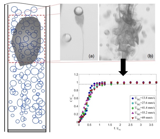
2.2. Mixing Time Measurement

The mixing experiments consisted of the measurement of the evolution of a passive scalar (i.e., dye) within the bubble column. The passive scalar (food color, chef-o-van) was injected at the column mid-height using a vertical tube with an inner and outer diameter of 0.6 mm and 1.6 mm, respectively. The tube was placed in a vertically downward orientation to inject the dye at the center of the column. The injection point was located 0.45 m above the sparger. For each experiment, 0.6 mL of dye was injected at a constant rate of 0.4 mL/min using a volumetric syringe pump (NE-300, New Era Pump Systems, Inc., Farmingdale, NY, USA). The Reynolds number (Reps = 4Qps/πdinjνps) based on dye properties (i.e., νps), dye volumetric flow rate (Qps), and injector tube diameter (dps) was calculated to be Reps ~ 20 in all the experiments. The 90 s delay was to allow the dye to come to rest at the bottom of the bubble column. Inspections showed that within the measurement section, the dye concentration remained negligible prior to air injection. The start of air bubble injection sets the origin of diffusion time in each test and quantitative measurements continued until one minute after air injection.
A Canon EOS 70D DSLR camera was used to capture monochrome images of the bubble mixing. This camera had an APS-C CMOS image sensor (22.5 mm × 15 mm) with a maximum resolution of 5472 × 3648 pixels. The camera pixel size was 4.1 μm × 4.1 μm with a 14-bit depth. A Canon 60 mm 1:2.8 camera lens was employed for image acquisition. Recordings of bubble mixing were carried out at a resolution of 1280 × 720 pixels, which produced a field-of-view of 120 mm × 67 mm. For the current work, recordings were acquired from before dye injection until after the dye was fully mixed (homogeneous). Recordings of bubble mixing at 60 Hz were acquired to obtain the temporal evolution of the dye concentration. During the experiments, the camera exposure time was set to 312 μs. The column was backlit with a LED panel (Daylight 1200, Fovitec StudioPRO, Irvine, CA, USA). The LED panel could deliver up to 13,900 illumination flux (5600 K color temperature) at 1 m. Light was uniformly diffused using a 3 mm thick white acrylic sheet.
The temporal evolution of the dye concentration was quantified from the change in the grayscale value of the images from the mixing process. First, an in-situ calibration was carried out to correlate the grayscale value of the images with the injected mass of dye. Figure 3 shows the calibration curve that Elbing et al. [27] recommended, whereby mixing characterization via tracking the light intensity in optical images should be carried out in a range at which exists a linear correlation between the concentration of additive solution and light intensity. In the current work, a maximum of 0.6 mL of the dye was used for mixing time. In all the experiments, prior to air injection, a batch of dye forms at the bottom of the column; mixing time begins as soon as bubbles reach and pass through the dye cloud. The average grayscale across the column section at the column mid-height was used for characterizing the mixing process. When the dye reached the measurement section due to bubble diffusion, it obstructs the light and reduces the grayscale in the background of the bubble images. The mixing time ( t ) was defined as the time required for the dye concentration to reach the 95% level of the fully mixed condition. In all conditions tested, the dye concentration after five minutes of bubble injection was used as the fully mixed condition, which was determined based on visual inspection.
ImageJ (1.49v, National Institutes of Health (NIH), Bethesda, MD, USA) [28,29,30,31], a common open access image-processing program, was used for obtaining the grayscale levels from the bubble mixing images. Grayscale levels were measured at the mid-height location. Bubbles were identified and filtered out of the processed images to obtain the grayscale within the liquid phase. Figure 4 shows example results of the grayscale distribution along the column diameter. Filtering the bubbles causes the post-processed profile to be non-continuous. However, there are sufficient data points, even at the highest void fractions tested, to approximate the distribution of dye in the radial direction. In addition, Figure 4 shows that the aforementioned approach successfully captures the temporal evolution of the dye concentration in bubble mixing.

2.3. Bubble Size Measurement

Bubble images were processed to measure the bubble size using the ImageJ software. Within ImageJ, an edge detection algorithm was used to sharpen the bubble edges, subtract the background, and apply a grayscale threshold to convert the 12-bit images to binary images. A subset of images from each condition were manually processed and then used to determine the appropriate grayscale threshold. It is worth mentioning that the bubble images became darker in the background as the number of bubbles increased. Therefore, a range of acceptable threshold values was explored and had a 2% variation on the measured bubble size. Interested readers are referred to Mohagheghian et al. [20,21] for more details on the image processing scheme used in the current work. Uncertainty associated with the spatial calibration and image processing was estimated to result in a bubble size uncertainty of less than 8%. In the current work, the imaging system and processing scheme are able to resolve bubbles ≥0.2 mm in diameter. Figure 5 provides an example of a bubble image with the identified bubbles using the appropriate threshold outlined. Figure 5 also depicts that the processing algorithm would only identify in-focus bubbles and exclude out-of-focus bubbles, which minimizes the impact of out-of-plane bubble locations on the spatial calibration. Figure 5 also shows that even with a proper threshold, overlapping and defective bubbles can contaminate the size distributions. Consequently, each image was manually inspected for the aforementioned issues and impacted bubbles were removed from the population sample.
Bubbles were approximated as ellipsoids in shape and the equivalent diameter (d) of a sphere with the same cross sectional area (Ab),
d = α 2 A R   ,
was used as the bubble size representative length scale (Ab = παβ/4). Here, α and β are the major and minor bubble axes, respectively, (see Figure 5) and AR is the aspect ratio (α/β) of the bubble. The cross-sectional area, the bubble centroid location, and the aspect ratio were calculated for identified bubbles in ImageJ. The Sauter mean diameter (d32) is a common measure of average bubble size for a sample of bubbles (di, where each individual bubble is calculated from Equation (2)) and is defined as the ratio of the representative bubble volume to the bubble surface area,
d 32 = i = 1 n d i 3 i = 1 n d i 2   .

2.4. Void Fraction Measurement

Void fraction is defined as the ratio of gas volume to the total volume of the system. In the current work, void fraction was calculated from the differential pressure (∆P) along the column height during operation. A U-tube monometer was employed to obtain the average void fraction between two pressure taps that had 8D vertical separation along the column height (see Figure 2). Void fraction was calculated using
ε = ( ρ o ρ L 1 ) Δ h Δ H   ,
where ∆H is the vertical distance between the pressure taps, ρL and ρo are the density of liquid (water) and the monometer working fluid, respectively, and ∆h is the reading (height difference) from the monometer. Red gage oil (SG = 0.826) was used as monometer working fluid.

2.5. Test Matrix

To characterize the mixing time, the effect of gas superficial velocity (USG = 4QG/πD2) on mixing time was investigated in a static bubble column. A series of experiments were carried out to investigate the temporal evolution of the passive scalar within a homogenous bubble swarm. Table 1 gives the details of each tested condition in a static air-water bubble column. Within the gas superficial velocity range tested in the present work, the bubble column operated in the homogenous regime and the void fraction was a linear function of gas superficial velocity. Following the static bubble column experiments, a systematic study of mixing under vertical vibration was carried out.
Table 2 provides the test matrix used to study the effect of vibration condition on mixing time in a vibrating (air-water) bubble column. In each test, bubble size distribution and void fraction were measured along with the mixing time. The specific input power in both static and vibration scenarios were calculated using the following relationship,
P m = g U S G + 1 2 A 2 ω 3 .
Here A and ω are the vibration amplitude and angular velocity (2πf), respectively. Thus, for the static case, the second term on the right hand side is zero. It is worth mentioning that Equation (3) was presented and used by Knopf et al. [32] in vibrating bubble column research.

3. Bubble Induced Mixing in a Static Bubble Column

The effect of gas superficial velocity on bubble induced mixing was tested by tracking the temporal evolution of the normalized concentration of a passive scalar at the column mid-height. To assure that the present approach provides consistent results, a series of experiments were conducted to investigate the repeatability of the results. Five different gas superficial velocities were selected (see Table 1), and at different times, each condition was repeated ten times. Figure 6 shows the averaged temporal mixing of all ten repetitions for each gas superficial velocity tested. Here, C is the temporal concentration of the dye and C is the concentration of the dye when it was fully mixed. The mixing time ( t ) was defined as the time when the normalized concentration C/C exceeds 0.95 and remains steady. Figure 6 shows that for all conditions, the mixing rate is relatively constant and it is fair to say that the time evolution of the dye concentration is insensitive to gas superficial velocity and the data collapsed within the measurement uncertainty on a single curve using this normalization. For all the data in Figure 6, t = 16 s, which suggests that the mixing time is not sensitive to the gas superficial velocity within the range tested.
Bubble images were manually inspected to verify that the mixing time was constant and independent of gas superficial velocity within the range tested. Figure 7 shows representative images of bubble mixing at t = 8 s, where t is measured from the start of mixing. It can be seen that increasing the gas superficial velocity increases the void fraction, number of the bubbles, and bubble size. However, the mixing rate remained unchanged. The dominant mixing mechanism was identifying by performing detailed analysis of the bubble images. There was no observation of a mean flow or wake capture. Therefore, in the absence of liquid circulation (e.g., oscillating bubble plume) the primary active mixing mechanism was associated with the induced liquid velocity fluctuations. Consequently, this suggests that bubble mixing due to induced liquid velocity fluctuations was independent of void fraction within the range tested (2% < ε < 6%). These results are in agreement with the results of Alméras et al. [7] and Bouche et al. [8], which found that the diffusion coefficient(s) are insensitive to void fraction within the aforementioned range. A generalized correlation was formulated to provide a mathematical model for the temporal evolution of dye concentration under bubble-induced diffusion in the present work. It was found that an error-function (erf) provides a reasonable fit to the data; Figure 8 provides an example of this temporal evolution. It is worth mentioning that the error bars in Figure 8 represent 4% of the C/C value. The normalized temporal evolution data are well represented with the error-function curve fit,
C C = 0.55 e r f ( 2.7 t t 1 ) + 0.45 .
The effect of viscosity on the mixing time under bubble induced diffusion was tested by fixing the gas superficial velocity (USG = 27.6 mm/s, ε = 4.4%) and testing with 85% (aqueous) solution of glycerin (ρL = 1224 kg/m3; μL = 0.16 Pa.s; σ = 0.065 N/m), which significantly increased the dynamic viscosity relative to water (by two orders of magnitude). Figure 9 compares the average bubble-induced mixing time in water with that of a single test with the glycerin solution. Note that increasing the dynamic viscosity increases the void fraction (by 30%), but it was still within the range tested by Alméras et al. [7]. Thus, these results show that increasing the dynamic viscosity decreases the bubble-induced mixing rate. Viscosity dissipates the velocity agitations induced by the bubble wakes. This suggests that bubble-induced diffusion is a (bubble) Reynolds number depended mechanism. Detailed observations were carried out to inspect the mixing mechanism in the glycerin solution. In the present study, the bubble mixing was primarily via bubble-induced velocity agitations and not wake capture to even with increased dynamic viscosity (i.e., reducing the bubble Reynolds number).

4. Effect of Vertical Vibration on Bubble-Induced Mixing

This work intended to study the effect of vertical vibration on the mixing time of a passive scalar under bubble-induced mixing. Table 2 provides all thirty-two tested vibration conditions as well as measured bubble size (d32—Sauter mean diameter), void fraction (ε), and the mixing time ( t ). Comparison between the mixing time in static and vibrating experiments shows that at lower amplitudes tested, bubble terminal velocity experiences significant retardation, which, in turn, lowers the intensity of the induced velocity agitations, resulting in an increased mixing time (Table 2, experiments 1–22). This observation suggest that bubble mixing is related to the bubble Reynolds number and shows minimal sensitivity to void fraction within the tested range. Figure 10 and Figure 11 show the temporal mixing between static and vibrating conditions to compare the mixing rate in static and vibrating experiments at equivalent instances. Figure 10 presents the static experiment #1 from Table 1 versus vibrating experiment #1 from Table 2, and shows that the vibration decelerates the bubble-induced mixing. This could be observed in Figure 10 and Figure 11 by comparing the background darkness of each image pair in the same column. Figure 11 presents the static experiment #5 from Table 1 versus vibrating experiment #4 from Table 2, and shows that as vibration frequency was increased, the bubble breakage and deformation from the oscillating pressure field under vibration enhanced the intensity of the bubble induced velocity agitations and compensated for the retardation effect. Note that even when frequency was increased, the vibration mixing was still slightly slower than the static condition. So far, it can be seen that vibration provides no enhancement of bubble-induced mixing. More experiments were carried out to better explore the effect of vibration on bubble-induced mixing.
Detailed observations from additional test conditions (Table 2 experiments 23–32) revealed that higher amplitudes enhance the bubble mixing by means of aggregated bubble clouds and void fraction gradients that in turn produce a large-scale recirculation in the bubble column. Note that under vibration, the operation range was limited since higher frequency and amplitude combinations produced unintended surface entrainment and surface sloshing, which results in an uncontrolled test environment. For all conditions tested (Table 2), the vertical vibrations produced solid body movement within the column and consequently, no manipulation of the liquid flow field occurs in the absence of bubble injection. This was experimentally confirmed via flow visualization (dye) over the range of vibration conditions without bubble injection. Mohagheghian et al. [21] reported that the current experimental setup surface sloshing occurs when the transient buoyancy number,
B j = ρ L H A 2 ω 4 p 0 g ,
is larger than 0.3. In the current study, all the vibrating test conditions had Bj < 0.3. Note that in Equation (7), p0 is the ambient pressure and g is the gravitational acceleration. The transient buoyancy number is the product of scaled vibration acceleration (2/g) and scaled vibration pressure amplitude (ρLHAω2/p0) and has been widely used in vibrating bubble column research to identify the levitation condition [33,34,35,36,37,38,39]; in more recent studies, Bj was used to scale the void fraction and mass transfer in vibrating bubble columns [21,25,40,41,42,43,44].
The effect of vertical vibration on mixing of a passive scalar under bubble induced diffusion was further studied by investigating the effect of vibration frequency and amplitude independently. First, a set of tests were performed with the vibration amplitude fixed (A = 0.6 mm) and the frequency varied (f = 8, 15, 18.8 and 23.3 Hz). The gas superficial velocity was also held constant (USG = 11 mm/s). Figure 12 presents the temporal evolution of the normalized dye concentration under these vibration conditions as well as the static mixing curve represented by Equation (6). In Section 3 (static experiments), it is shown that in the conditions listed in Table 1, the mixing time is independent of gas superficial velocity; therefore, it is appropriate to use Equation (6) to compare the mixing time in static and vibrating experiments. These results show a measurable deceleration in mixing (i.e., increase in mixing time) relative to the static cases, for which the mixing times and operation conditions are provided in Table 3. In addition, the temporal concentrations exhibit larger fluctuations with vibration than the static results. Figure 12 shows that increasing the frequency accelerates the mixing process within the first 15 s of the experiment and that vibration produces significant fluctuations in the normalized concentration. Detailed inspections showed that these fluctuations are created by high-concentration flow structures in the bubble column. In other words, vibration produces a gradient of void fraction via modifying the special distribution of the gas phase which, in turn, creates large-scale recirculation. The mixing time ( t ) in vibrating experiments was defined as the time required for the dye concentration to reach the 95% level of the fully mixed condition and remains the same value or higher for the rest of tests. With this in mind, the results show that for all vibrating experiments listed in Table 3, vibration decelerated the bubble-induced mixing process.
Manual inspection of raw bubble images revealed that in addition to retardation, vibration modifies the spatial distribution of the gas phase (bubbles). Representative instantaneous images of the bubbles mixing under vibration at various frequencies are shown in Figure 13. These images show that vibration modifies the bubble size (Figure 13a–c) as well as the spatial distribution (Figure 13d). The spatial distribution creates void fraction gradients, which induces large scale recirculation within the column that translates the dye cloud along the column. Therefore, vibration has a dual effect on bubble-induced mixing; on the one hand, vibration decelerates the mixing due to retardation, and on the other hand, vibration improves mixing by creating large-scale recirculation zones due to void fraction gradients.
Next, the effect of vibration amplitude on the mixing time was investigated by holding the frequency (f = 9.5 Hz) and superficial gas velocity (USG = 11 mm/s) constant while varying the vibration amplitude (A = 1.2, 1.6, 1.9, 3.3 and 5.7 mm). The temporal evolution of the mixing for these conditions is shown in Figure 14. The resulting mixing times, as well as the corresponding operation conditions, are provided in Table 4. The transient behavior (i.e., prior to being fully mixed) appears to be relatively insensitive to the vibration amplitude, unlike that observed with variations in the frequency. This is apparent when examining the first 5 s during bubble injection. However, the mixing time appears to be insensitive to the vibration amplitude until above ~1.4 mm and above this limit, there is a decrease in the mixing time that is proportional to the vibration amplitude.
Investigating the raw images from the bubble induced mixing shows that a similar effect to that observed with vibration frequency is occurring; increasing the amplitude has a significant impact on bubble size and spatial distribution. This can be seen in Figure 15, where instantaneous images of the bubble mixing under vibration at various amplitudes are shown. At the highest amplitudes tested in the present work (A = 3.3 and 5.7 mm), a sensible improvement in the mixing performance was noticed (see Table 4). The improved mixing time is due to large-scale recirculation zones in the column. Therefore, based on the results of the present work, it is concluded that within these operation ranges, vibration has a dual effect on mixing, bubble retardation decelerates the mixing process and void fraction gradients produce recirculation and accelerate the mixing.
The mixing times for all the test conditions are included in Table 2; these results show that the mixing times are consistently lower than static conditions when Bj ~ 0.1. A dimensionally reasoned scaling was used to identify a correlation between the observed mixing times scaled with the bubble time scales (tUSG/εd32) and the transient buoyancy number (Bj). Note that from the definition of superficial gas velocity and void fraction, control volume shows that the average bubble rise velocity is equal to USG/ε. The experimental data are scaled using this proposed correlation and then fitted with a power-law curve fit,
t U S G ε d 32 = 2.0749 [ B j ] 1.256 .
The scaled experimental data are plotted in Figure 16 along with the resulting fitted correlation from Equation (8). The results follow the general trend of the proposed correlation.

5. Conclusions

This study presents a characterization of mixing time of a passive scalar under bubble-induced diffusion in a vertically vibrated bubble column. Bubble size and void fraction were measured in addition to the mixing time to study the effect of multiphase parameters as well as the specific input power on the mixing time. A passive scalar was introduced into the column using a volumetric pump forming a stationary cloud (batch) of dye, mixing was initiated by bubbling the column, and the entire process was timed and recorded from the dye injection until the reaching a fully mixed condition. The temporal evolution of the mixing was characterized by tracking of the background grayscale level in the bubble images. A series of image processing tools was developed for this task to filter the bubbles from each image and track the grayscale value within only the liquid phase.
In the static tests, increasing the gas superficial velocity did not accelerate the bubble-induced mixing process. A detailed study of the temporal evolution of dye concentration in the static bubble column shows that the temporal concentration of the dye can be accurately represented with an error function (erf) of time. Investigation of the mixing time within a highly viscous liquid suggests that the bubble-induced diffusion is a Reynolds number based on bubble properties depended phenomenon. In addition, investigation of the mixing time under vibration showed that vibration has a dual effect on the mixing time. In lower vibration amplitude, vibration decelerates the mixing due to bubble retardation. However, bubble aggregation at higher vibration amplitude provides a slightly faster mixing performance due to void fraction gradients. A dimensional analysis was employed to find a correlation between the non-dimensional mixing time and the transient buoyancy number (Bj).

Author Contributions

Conceptualization, S.M. and B.R.E.; Data curation, S.M.; Formal analysis, S.M.; Funding acquisition, B.R.E.; Investigation, S.M.; Methodology, S.M., A.J.G. and B.R.E.; Project administration, B.R.E.; Resources, A.J.G. and B.R.E.; Supervision, A.J.G. and B.R.E.; Validation, S.M.; Visualization, S.M.; Writing—original draft, S.M.; Writing—review & editing, S.M., A.J.G. and B.R.E. All authors have read and agreed to the published version of the manuscript.

Funding

This research was funded, in part, by B.R.E.’s Halliburton Faculty Fellowship endowed professorship.

Acknowledgments

The authors would like to thank Adam Still for the initial design and fabrication of the facility as well as assistance with the initial operation of it.

Conflicts of Interest

The authors declare no conflict of interest.

Nomenclature

SymbolDescriptionUnit
aPhase interfacial area[mm2]
AVibration amplitude[mm]
ARBubble aspect ratio[-]
BjTransient buoyancy (Bjerknes) number[-]
CConcentration of the passive scalar[ppm]
dDiameter[mm]
DBubble column diameter[mm]
fVibration frequency[s−1]
gGravitational acceleration[ms−2]
HLiquid column height[mm]
PPower input[kgm3s−3]
ppressure[kgm−1s−2]
QVolumetric flow rate[mLmin−1]
rPore radius[μm]
ReReynolds number[-]
SGSpecific gravity[-]
tTime[s]
UPhase velocity[mms−1]
Greek Letters and Symbols
∆HVertical distance between two pressure taps[m]
∆hMonometer reading[m]
∆PDifferential pressure[kg m−1s−2]
αBubble major axis[mm]
βBubble minor axis[mm]
εVoid fraction[-]
μDynamic Viscosity[kgm−1s−1]
νKinematic viscosity[m2s−1]
ρDensity[kgm−3]
σSurface tension[kgs−2]
Φscale of segregation[-]
ωVibration angular velocity[s−1]
Subscripts
injInjector tube
psPassive scalar (dye)
pCharacteristics of the pore sparger
SGSuperficial gas
LLiquid (phase)
oMonometer working fluid
mSpecific quantities
32Suater mean diameter
0Ambient properties
GGas phase
bBubble
capCapillary
Steady state condition

References

  1. Besnaci, C.; Roig, V.; Risso, F. Mixing induced by a random dispersion at high particulate Reynolds number. In Proceedings of the 7th International Conference on Multiphase Flow, Tampa, FL, USA, 30 May–4 June 2010. [Google Scholar]
  2. Lance, M.; Bataille, J. Turbulence in the liquid phase of a uniform bubbly air-water flow. J. Fluid Mech. 1991, 222, 95–118. [Google Scholar] [CrossRef]
  3. Martínez-Mercado, J.; Palacios-Morales, C.A.; Zenit, R. Measurement of pseudoturbulence intensity in monodispersed bubbly liquids for 10 < Re < 500. Phys. Fluids 2007, 19, 103302. [Google Scholar]
  4. Riboux, G.; Risso, F.; Legendre, D. Experimental characterization of the agitation generated by bubbles rising at high Reynolds number. J. Fluid Mech. 2010, 643, 509–539. [Google Scholar] [CrossRef]
  5. Mercado, J.M.; Gomez, D.C.; Van Gils, D.; Sun, C.; Lohse, D. On bubble clustering and energy spectra in pseudo-turbulence. J. Fluid Mech. 2010, 650, 287–306. [Google Scholar] [CrossRef] [Green Version]
  6. Mendez-Diaz, S.; Serrano-Garcia, J.C.; Zenit, R.; Hernandez-Cordero, J.A. Power spectral distributions of pseudo-turbulent bubbly flows. Phys. Fluids 2013, 25, 043303. [Google Scholar] [CrossRef]
  7. Alméras, E.; Risso, F.; Roig, V.; Cazin, S.; Plais, C.; Augier, F. Mixing by bubble-induced turbulence. J. Fluid Mech. 2015, 776, 458–474. [Google Scholar] [CrossRef] [Green Version]
  8. Bouche, E.; Cazin, S.; Roig, V.; Risso, F. Mixing in a swarm of bubbles rising in a confined cell measured by mean of PLIF with two different dyes. Exp. Fluids 2013, 54, 1552. [Google Scholar] [CrossRef] [Green Version]
  9. Bouche, E.; Roig, V.; Risso, F.; Billet, A.M. Homogeneous swarm of high-Reynolds-number bubbles rising within a thin gap. Part 2. Liquid dynamics. J. Fluid Mech. 2014, 758, 508–521. [Google Scholar] [CrossRef] [Green Version]
  10. Alméras, E.; Cazin, S.; Roig, V.; Risso, F.; Augier, F.; Plais, C. Time-resolved measurement of concentration fluctuations in a confined bubbly flow by LIF. Int. J. Multiph. Flow 2016, 83, 153–161. [Google Scholar] [CrossRef] [Green Version]
  11. Alméras, E.; Plais, C.; Euzenat, F.; Risso, F.; Roig, V.; Augier, F. Scalar mixing in bubbly flows: Experimental investigation and diffusivity modelling. Chem. Eng. Sci. 2016, 140, 114–122. [Google Scholar] [CrossRef] [Green Version]
  12. Alméras, E.; Plais, C.; Roig, V.; Risso, F.; Augier, F. Mixing mechanisms in a low-sheared inhomogeneous bubble column. Chem. Eng. Sci. 2018, 186, 52–61. [Google Scholar] [CrossRef] [Green Version]
  13. Besagni, G.; Inzoli, F.; Ziegenhein, T. Two-Phase Bubble Columns: A Comprehensive Review. ChemEngineering 2018, 2, 13. [Google Scholar] [CrossRef] [Green Version]
  14. Mareuge, I.; Lance, M. Bubble-induced dispersion of a passive scalar in bubbly flows. In Proceedings of the 2nd International Conference on Multiphase Flow, Kyoto, Japan, 3–7 April 1995. PT1-3–8. [Google Scholar]
  15. Abbas, M.; Billet, A.M.; Roig, V. Experiments on mass transfer and mixing in a homogeneous bubbly flow. In ICHMT Digital Library Online; Begel House Inc: Danbury, CT, USA, 2009. [Google Scholar]
  16. Loisy, A. Direct Numerical Simulation of Bubbly Flows: Coupling with Scalar Transport and Turbulence. Ph.D. Thesis, Université de Lyon, Lyon, France, 2016. [Google Scholar]
  17. Wiemann, D.; Mewes, D. Prediction of backmixing and mass transfer in bubble columns using a multifluid model. Ind. Eng. Chem. Res. 2005, 44, 4959–4967. [Google Scholar] [CrossRef]
  18. Radl, S.; Khinast, J.G. Multiphase flow and mixing in dilute bubble swarms. AICHE J. 2010, 56, 2421–2445. [Google Scholar] [CrossRef]
  19. Mohagheghian, S.; Elbing, B.R. Study of bubble size and velocity in a vibrating bubble column. In Proceedings of the ASME 2016 Fluids Engineering Division Summer Meeting Collocated with the ASME 2016 Heat Transfer Summer Conference and the ASME 2016 14th International Conference on Nanochannels, Microchannels, and Minichannels, Washington, DC, USA, 10–14 July 2016; p. V01BT33A012. [Google Scholar]
  20. Mohagheghian, S.; Elbing, B.R. Characterization of Bubble Size Distributions within a Bubble Column. Fluids 2018, 3, 13. [Google Scholar] [CrossRef] [Green Version]
  21. Mohagheghian, S.; Still, A.; Elbing, B.; Ghajar, A. Study of bubble size, void fraction, and mass transport in a bubble column under high amplitude vibration. ChemEngineering 2018, 2, 16. [Google Scholar] [CrossRef] [Green Version]
  22. Mohagheghian, S. Study of Bubbly and Annular Flow Using Quantitative Flow Visualization. Ph.D. Thesis, Mechanical & Aerospace Engineering, Oklahoma State University, Stillwater, OK, USA, 2019. [Google Scholar]
  23. Besagni, G.; Inzoli, F.; Ziegenhein, T.; Lucas, D. Computational Fluid-Dynamic modeling of the pseudo-homogeneous flow regime in large-scale bubble columns. Chem. Eng. Sci. 2017, 160, 144–160. [Google Scholar] [CrossRef]
  24. Wilkinson, P.M.; Spek, A.P.; van Dierendonck, L.L. Design parameters estimation for scale-up of high-pressure bubble columns. AICHE J. 1992, 38, 544–554. [Google Scholar] [CrossRef]
  25. Still, A. Multiphase Phenomena in a Vibrating Bubble Column Reactor. Master’s Thesis, Mechanical & Aerospace Engineering, Oklahoma State University, Stillwater, OK, USA, 2010. [Google Scholar]
  26. Houghton, G.; McLean, A.M.; Ritchie, P.D. Mechanism of formation of gas bubble-beds. Chem. Eng. Sci. 1957, 7, 40–50. [Google Scholar] [CrossRef]
  27. Elbing, B.R.; Winkel, E.S.; Ceccio, S.L.; Perlin, M.; Dowling, D.R. High-reynolds-number turbulent-boundary-layer wall-pressure fluctuations with dilute polymer solutions. Phys. Fluids 2010, 22, 085104. [Google Scholar] [CrossRef]
  28. Abràmoff, M.D.; Magalhães, P.J.; Ram, S.J. Image processing with ImageJ. Biophotonics Int. 2004, 11, 36–42. [Google Scholar]
  29. Peters, R.; Rasband, W.S. ImageJ; US National Institutes of Health: Bethesda, MD, USA, 2012.
  30. Rasband, W.S. ImageJ. Available online: http://imagej.nih.gov/ij (accessed on 16 April 2013).
  31. Schneider, C.A.; Rasband, W.S.; Eliceiri, K.W. NIH Image to ImageJ: 25 years of image analysis. Nat. Methods 2012, 9, 671. [Google Scholar] [CrossRef] [PubMed]
  32. Knopf, F.C.; Waghmare, Y.; Ma, J.; Rice, R.G. Pulsing to improve bubble column performance: II. Jetting gas rates. AIChE J. 2006, 52, 1116–1126. [Google Scholar] [CrossRef]
  33. Jameson, G.J.; Davidson, J.F. The motion of a bubble in a vertically oscillating liquid: Theory for an inviscid liquid, and experimental results. Chem. Eng. Sci. 1966, 21, 29–34. [Google Scholar] [CrossRef]
  34. Jameson, G.J. The motion of a bubble in a vertically oscillating viscous liquid. Chem. Eng. Sci. 1966, 21, 35–48. [Google Scholar] [CrossRef]
  35. Houghton, G. Particle trajectories and terminal velocities in vertically oscillating fluids. Can. J. Chem. Eng. 1966, 44, 90–95. [Google Scholar]
  36. Rubin, E. Behavior of gas bubbles in vertically vibrating liquid columns. Can. J. Chem. Eng. 1986, 46, 145–149. [Google Scholar] [CrossRef]
  37. Foster, J.M.; Botts, J.A.; Barbin, A.R.; Vachon, R.I. Bubble trajectories and equilibrium levels in vibrated liquid columns. J. Basic Eng. 1986, 90, 125–132. [Google Scholar] [CrossRef]
  38. Marmur, A.; Rubin, E. Viscous effect on stagnation depth of bubbles in a vertically oscillating liquid column. Can. J. Chem. Eng. 1976, 54, 509–514. [Google Scholar] [CrossRef]
  39. Still, A.L.; Ghajar, A.J.; O’Hern, T.J. Effect of amplitude on mass transport, void fraction and bubble size in a vertically vibrating liquid-gas bubble column reactor. In Proceedings of the ASME Fluids Engineering Summer Meeting-FEDSM2013-16116, Incline Village, NV, USA, 7–11 July 2013; pp. 7–11. [Google Scholar]
  40. Waghmare, Y.G.; Dorao, C.A.; Jakobsen, H.A.; Knopf, F.C.; Rice, R.G. Bubble size distribution for a bubble column reactor undergoing forced oscillations. Ind. Eng. Chem. Res. 2009, 48, 1786–1796. [Google Scholar] [CrossRef]
  41. Waghmare, Y.G.; Knopf, F.C.; Rice, R.G. The Bjerknes effect: Explaining pulsed-flow behavior in bubble columns. AICHE J. 2007, 53, 1678–1686. [Google Scholar] [CrossRef]
  42. Waghmare, Y.G.; Rice, R.G.; Knopf, F.C. Mass transfer in a viscous bubble column with forced oscillations. Ind. Eng. Chem. Res. 2008, 47, 5386–5394. [Google Scholar] [CrossRef]
  43. Budzyński, P.; Dziubiński, M. Intensification of bubble column performance by introduction pulsation of liquid. Chem. Eng. Process. 2014, 78, 44–57. [Google Scholar] [CrossRef]
  44. Budzyński, P.; Gwiazda, A.; Dziubiński, M. Intensification of mass transfer in a pulsed bubble column. Chem. Eng. Process. 2017, 112, 18–30. [Google Scholar] [CrossRef]
Figure 1. Diffusion of a passive scalar (dye shown as the darker regions) under bubble induced mixing via (a) wake transport and (b) bubble-induced turbulence.
Fluids 05 00006 g001
Figure 2. Schematic of the experimental setup.
Fluids 05 00006 g002
Figure 3. Change of grayscale value with dye injection.
Fluids 05 00006 g003
Figure 4. Grayscale measurement for evaluation of the temporal evolution of the dye concentration in bubble mixing.
Fluids 05 00006 g004
Figure 5. Sample of processed bubble-image using ImageJ for bubble size measurements.
Fluids 05 00006 g005
Figure 6. Temporal evolution of the normalized concentration and the effect of gas superficial velocity on mixing time in a bubble swarm.
Fluids 05 00006 g006
Figure 7. Instantaneous images of bubble mixing at t = 8 s for (a) USG = 13.8 mm/s, ε = 2.5%; (b) USG = 27.6 mm/s, ε = 3.3%; (c) USG = 41.4 mm/s, ε = 4.2%; and (d) USG = 55.2 mm/s, ε = 5.9%.
Fluids 05 00006 g007
Figure 8. A correlation for the temporal evaluation of the dye concentration under bubble-induced mixing without vertical vibration.
Fluids 05 00006 g008
Figure 9. A comparison between the mixing time in water (ε = 3.4%) and 85% (aqueous) solution of glycerin (ε = 4.4%) at USG = 27.6 mm/s.
Fluids 05 00006 g009
Figure 10. Instantaneous images of mixing of the dye in (ad) static (experiment #1 from Table 1) and (eh) vibrating (vibrating experiment #1 from Table 2) bubble column.
Fluids 05 00006 g010
Figure 11. Instantaneous images of mixing of the dye in (ad) static (experiment #5 from Table 1) and (eh) vibrating (vibrating experiment #4 from Table 2) bubble column.
Fluids 05 00006 g011
Figure 12. Effect of vibration frequency on mixing time, A = 0.6 mm and USG = 11 mm/s. The horizontal dashed line represents the fully mixed condition (C/C = 0.95) and the vertical dashed line t = 9 s.
Fluids 05 00006 g012
Figure 13. Instantaneous images of mixing at t = 8 s (A = 0.68 mm, USG = 11 mm/s) for (a) f = 8 Hz, Pm = 0.136 W/kg; (b) f = 15 Hz, Pm = 0.259 W/kg; (c) f = 18.8 Hz, Pm = 0.406 W/kg; (d) f = 23.3 Hz, Pm = 0.667 W/kg.
Fluids 05 00006 g013
Figure 14. Effect of vibration amplitude on mixing time with f = 9.5 Hz and USG = 11 mm/s.
Fluids 05 00006 g014
Figure 15. Instantaneous images of mixing at t = 10 s with various vibration amplitudes (f = 9.5 Hz, USG = 11 mm/s) for (a) A = 0.6 mm, Pm = 0.146 W/kg; (b) A = 1.2 mm, Pm = 0.261 W/kg; (c) A = 1.9 mm, Pm = 0.492 W/kg; (d) A = 3.3 mm, Pm = 1.266 W/kg.
Fluids 05 00006 g015
Figure 16. Scaled mixing time plotted versus scaled specific input power. The experimental data are compared against a dimensionally reasoned correlation.
Fluids 05 00006 g016
Table 1. Test matrix for the static bubble column configuration.
#USG (mm/s)Pm (W/kg)ε (-)d32 (mm)t (s)
113.80.142.6%2.3516
227.60.273.4%2.5116
341.40.414.2%2.5616
455.20.545.0%2.6916
569.00.685.9%2.8616
Table 2. Summary of test conditions with vertical vibrations.
#USG (mm/s)A (mm)f (Hz)Pm (W/kg)Bj (-)ε (-)d32 (mm)t (s)
19.60.69.70.130.0021.1%2.4525
212.40.614.50.260.0111.0%2.6425
327.60.615.40.430.0141.1%2.8825
431.70.620.10.670.0421.2%2.6020
5110.680.130.0011.1%2.4525
6110.6150.260.0131.0%2.6425
7110.618.80.400.0321.1%2.8825
8110.623.30.670.0761.2%2.6025
9110.69.50.150.0721.5%2.3525
10111.29.50.260.0081.7%2.0225
11111.211.50.380.0181.3%2.7735
12111.213.10.510.0301.7%3.0425
13111.214.30.630.0431.6%2.9430
14111.69.50.390.0071.5%2.7025
15111.6110.530.0161.4%3.0925
16111.6120.660.0271.4%3.1520
17111.6140.980.0382.5%2.3225
18111.99.50.490.0702.9%1.7416
19111.99.90.540.0252.1%2.7616
20111.910.80.670.0352.1%2.5417
21111.912.71.030.0672.2%2.7617
22111.9141.340.0992.5%2.7318
23113.39.51.270.0631.9%3.1310
24113.38.81.030.0473.0%3.0813
25113.39.71.340.0691.9%3.1310
26113.310.61.720.0982.0%3.0815
27113.311.52.160.1362.7%3.1313
28113.312.52.750.1902.3%2.9813
29115.782.170.0952.8%3.0211
30115.78.72.760.1333.9%2.8812
31115.79.53.560.1893.6%2.8211
32115.710.54.770.2823.9%2.4010
Table 3. Operation conditions used in Figure 12 to study the effect of vibration frequency on mixing time.
#USG (mm/s)A (mm)f (Hz)Pm (W/kg)t (s)
1110.680.1325
2110.6150.2625
3110.618.80.4125
4110.623.30.6725
Table 4. Operation settings used to study the effect of vibration amplitude on mixing time and the resulting mixing time.
#USG (mm/s)A (mm)f (Hz)Pm (W/kg)t (s)
1111.29.50.2625
2111.69.50.3925
3111.99.50.4916
4113.39.51.2710
5115.79.53.5611

