Article

Jovian Vortices and Jets

by
Glenn R. Flierl
1,*,
Philip J. Morrison
2,† and
Rohith Vilasur Swaminathan
1,†,‡
1
Department of Earth, Atmospheric and Planetary Sciences (EAPS), Massachusetts Institute of Technology (MIT), Cambridge, MA 02139, USA
2
Department of Physics and Institute for Fusion Studies, University of Texas at Austin, Austin, TX 78712, USA
*
Author to whom correspondence should be addressed.
Fluids 2019, 4(2), 104; https://doi.org/10.3390/fluids4020104
Submission received: 16 April 2019 / Revised: 15 May 2019 / Accepted: 16 May 2019 / Published: 3 June 2019
(This article belongs to the Collection Geophysical Fluid Dynamics)

Abstract

:
We explore the theory of isolated vortices in strongly sheared, deep zonal flows and the stability of these banded jets, as occur in Jupiter’s atmosphere This is done using the standard 2-layer quasigeostrophic model with the lower layer depth becoming infinite; however, this model differs from the usual layer model because the lower layer is not assumed to be motionless but has a steady configuration of alternating zonal flows. Steady state vortices are obtained by a simulated annealing computational method as generalized to fluid problems with constraints and also used in the used in the context of magnetohydrodynamics. Various cases of vortices with a constant potential vorticity anomaly atop zonal winds and the stability of the underlying winds are considered using a mix of computational and analytical techniques.

1. Introduction

A great red spot on Jupiter has been observed for centuries, with its present manifestation dating back to telescopic observation in 1830. With the technological observational advancements and spacecraft measurements of modern times, additional Jovian vortical features have been discovered as well as such features in other planets. Many theoretical ideas have been proposed, yet it seems at minimum the red spot is a vortex enmeshed in zonal flow.
The red spot has been modelled with various approaches. Solitary wave hlmodels [1] rely on long waves in the jets which are meridionally confined. Formally, they are highly asymmetric and weakly nonlinear. Theories of turbulent cascades leading to vortices in shear [2] generally do not have a complex alternating jet pattern and can be influenced by the walls. The more complex nonlinearity inherent in the shallow water equations predicts robust anticyclones but again these are generally embedded in a simpler external situation. Numerical studies with both shallow water [3] and conventional atmospheric models [4] have shown the possibility of robust vortices; our goal differs in that we will determine steady solutions for vortices in strong back-and-forth jets.
In this paper we investigate the conditions required for isolated vortices to exist in sheared zonal flows and the stability conditions for the maintenance of zonal winds. To this end we use the simple model of [3] to illustrate the basic concepts and to explore the sizes and shapes of the vortices. The model can be viewed as a version of the standard 2-layer quasigeostrophic (QG) model with the lower layer depth becoming infinite. Unlike the more common 1 1 2 -layer model, the lower layer is not assumed to be motionless but rather have a steady zonal flow, U ( y ) . Since vortex stretching produced in the lower layer by vertical movement of the interface is negligible, this flow can remain unchanged. We will call this a 1 3 4 -layer model to distinguish it from either the motionless deep layer case or the one in which the deep layer evolves.
In Section 2 we will review how the 1 3 4 -layer model emerges from the 2-layer model. Also in this section we review the noncanonical Hamiltonian formalism [5,6,7] and briefly describe the Dirac bracket formalism, a Hamiltonian technique for the imposition of constraints. Both formalisms will be used later when we describe the simulated annealing (SA) procedure for obtaining steady states [8] and our generalization, the Dirac bracket simulated annealing (DBSA) procedure, introduced in [9].
Since the jets we consider can have β U y y changing sign, by the Rayleigh criterion they may be subject to rapid instability and break-down in either the 1 1 2 -layer model or standard 2-layer model. We will re-examine the idea that steady deep flow can stabilize the jets [10] using the energy-Casimir method and relate it to the existence of isolated vortices in Section 3. Furthermore, in [11] it was shown that the “two-beta” model reduces the growth rates significantly and limits the unstable waves to small scales. In this system, the deep fluid has a strong reverse β effect because of large vertical extent of the flows in the direction parallel to the rotation vector, which is appropriate when the entropy gradients are small [12].
In Section 4 we describe steady states composed of localized vorticity anomalies, vortex patches, embedded in the layer zonal flows. From the equations for the dynamics relative to the jets we obtain integral conditions that are useful for identifying the allowed positions of the anomalies. Importantly, we obtain an artificial dynamics that is adaptable to a contour dynamics version of the simulated annealing technique [9], which we will subsequently use to explore vortices in sinusoidal shear flows.
Section 5 begins with a description of the Hamiltonian structure for contour dynamics in the usual incompressible two-dimensional Euler context. This structure, which applies to nonsingle-valued contours, was described briefly in [7], but is due to two of us (GRF and PJM) and has been used and described in talks over the past 25+ years. Next we describe the DBSA technique in the context of contour dynamics, then, as a warmup, show how to use it to construct the Kirchhoff ellipse and its generalization with a background shear. Lastly in Section 5, we describe constraints needed for application of DBSA to Jovian vortices.
In Section 6 a variety of Jovian vortices on jets are constructed by the contour dynamics DBSA technique with Dirac constraints chosen to be the linear momenta. The case with β = 0 and a depth independent background flow is first considered. The parametric dependence of vortices centered at y = 0 , where the background flow reverses, is investigated. Using DBSA with β 0 , a vortex initially centered at y 0 relaxes to a state consistent with the constraints. A triangular shape reminiscent of observations of Jupiter is seen to naturally emerge. Lastly in this section, a comparison of the contour dynamics solutions to DBSA applied to the full 1 3 4 -layer model is made.
Finally, we conclude and summarize the paper in Section 7.

2. Model and Technique

2.1. Layer Model Review

The standard 2-layer model of GFD [13] is composed of two coupled advection equations,
t q i + [ ψ i , q i ] = 0 , i = 1 , 2 ,
where the potential vorticity in each layer is given by
q i = 2 ψ i + F i ( ψ 3 i ψ i ) + β i y .
Here 2 ψ = ψ x x + ψ y y with subscript denoting partial derivative, [ ψ , q ] = ψ x q y ψ y q x is the Jacobian or ordinary bracket operator, and i = 1 corresponds to the upper layer. This formulation allows for two stretching terms, F i , and (non-standard) two values for β i . For convenience we let F 1 = F and F 2 = δ F , whence δ = H 1 / H 2 is the ratio of the respective heights of the two layers.
The standard 1 1 2 -layer model is obtained by letting H 2 keeping H 1 fixed, with the additional assumption that ψ 2 0 . However, in this limit, the bottom layer may remain dynamic with a vorticity q 2 = 2 ψ 2 + β 2 y that evolves independent of the upper layer. If the lower layer resides in a steady state, say ψ 2 ( x ) , then we arrive at the 1 3 4 -layer model, with the upper layer dynamics in the presence of a steady deep layer flow governed by
t q + [ ψ , q ] = 0
with
q = ( 2 F ) ψ + F ψ 2 ( x ) + β y = ( 2 F ) ψ + T ( x ) ,
where without risk of confusion we have dropped the upper layer subscript 1. In Section 4 we will modify the dynamics of this 1 3 4 -layer model of (3) and (4) in such a way as to make it amenable to contour dynamics, which we will use subsequently in our analyses. Beforehand, let us now turn to the Hamiltonian description possessed by the model of (3) and (4).

2.2. Hamiltonian Structure of 1 3 4 -Layer Model

The model is a Hamiltonian field theory with its Hamiltonian functional H naturally being the total energy, kinetic plus potential, written as a functional of the dynamical variable q:
H [ q ] = 1 2 d x d x q ( x ) T ( x ) G ( x x ) q ( x ) T ( x ) ,
with d x = d x d y and the Green’s function, G ( x x ) , satisfying
( 2 F ) G ( x x ) = δ ( x x ) .
Because the dynamical variable q does not constitute a set of canonically conjugate field variables, the system takes noncanonical Hamiltonian form (see e.g., [5,6,7] for review) in terms of the following Poisson bracket:
{ A , B } = d x q ( x ) δ A δ q , δ B δ q = : d x δ A δ q J QG δ B δ q ,
where J QG : = [ q , · ] , the usual Jacobian expression defined above, is the Poisson operator. The bracket of (7) is a binary, antisymmetric operator, on functionals A , B , expressed in terms of their functional derivatives, δ A / δ q and δ B / δ q . Most importantly, the bracket of (7) also satisfies the Jacobi identity,
{ { A , B } , C } + { { B , C } , A } + { { C , A } , B } = 0 ,
for all functionals A , B , C . The Jacobi identity is the essence of being Hamiltonian—it guarantees the existence of a coordinate change to the usual canonically conjugate variables. With the Hamiltonian of (5) and the bracket (7), the time evolution of a functional A [ q ] is given by
t A = { A , H } .
For example, if A = q ( x ) = d x q ( x ) δ ( x x ) , then δ A / δ q = δ ( x x ) and, from definition of H,
δ H δ q = d x G ( x x ) q ( x ) T ( x ) = ψ ( x ) ,
Using these in (8) and (7) yields the 1 3 4 -layer model of (3) and (4).
The antisymmetry of the bracket ensures conservation of energy d H [ q ] / d t = 0 , while invariants P μ associated with other Noether symmetries satisfy { P μ , H } = 0 . In particular, if T is a function only of y, the zonal linear momentum,
P = d x y q ,
will be conserved:
d P d t = { P , H } = d x q y , δ H δ q = d x q x δ H δ q = d x v q = 0 ,
where the last equality follows given either periodic conditions or channel walls in the north and south. In the following we will mostly work in a reference frame translating at speed c (yet to be determined); this is equivalent to generating the motion with the Hamiltonian H c = H c P rather than H since δ H c / δ q = ψ c y . Similarly, T may possess other symmetries giving rise to the possible class of invariants
P μ [ q ] = d x ϕ μ ( x ) q
where ϕ μ { x , y , x 2 + y 2 } , corresponding to the momenta arising from two possible translational symmetries and L, the angular momentum arising from rotational symmetry, respectively.
Noncanonical Poisson brackets like (7) are degenerate and have constants of motion associated with the null space of the Poisson operator, J , the so-called Casimir invariants that satisfy
{ C [ q ] , B [ q ] } = 0
for all B [ q ] . Thus, they are constants of motion for any Hamiltonian. The bracket of (7) and consequently the QG equations have Casimir invariants of the form
C [ q ] = d x C ( q ( x ) )
with C ( q ) an arbitrary ordinary function; commonly used examples of such conserved functionals are the mean of the PV itself and the potential enstrophy
Z [ q ] = 1 2 d x q 2 .

2.3. Dirac Constraints and Steady States

In our previous work [9] we used simulated annealing, a technique based on Hamiltonian structure, to obtain a variety of steady states for QG flows. Our work generalized a technique previously introduced in [8] by adding a smoothing metric and, importantly, Dirac constraints that allow for the relaxation to a larger class of steady states. Starting with an initial state, the technique produces a dynamical system that rearranges parcels of fluid conserving each bit’s potential vorticity to achieve a maximum or minimum value of the Hamiltonian functional. This is done via a time-stepping of the PV by advecting with an artificial non-divergent velocity obtained from a so-called Dirac bracket, a generalized Poisson bracket that builds in arbitrary invariants, e.g., for two such invariants C 1 , 2 it has the form
{ A , B } D = { A , B } + { A , C 1 } { C 2 , B } { C 1 , C 2 } + { A , C 2 } { C 1 , B } { C 2 , C 1 } ,
where { C j , B } D = 0 for any functional B. In Dirac’s original work [14], the bracket { , } of (13) was the usual canonical Poisson bracket; however, his construction gives a bracket that satisfies the Jacobi identity for any bracket { , } which itself satisfies the Jacobi identity (see [15,16]).
Analogous to (7), associated with a bracket of the form of (13) is a Dirac Poisson operator, which we denote by J D . The relaxation dynamics is obtained by using a velocity field for advection obtained by essentially squaring J D . For PV-like dynamics we refer the reader to [9]. In Section 5 we tell this story more explicitly for the contour dynamics that we use in the present work. Before doing so, we first consider the stability of jets in the 1 3 4 -layer model setting, followed by a discussion of localized steady states.

3. Deep and Shallow Jets: Stability

3.1. General Form

Equilibrium states in some frame of reference satisfy δ F / δ q = 0 , where
F [ q ] = H [ q ] λ μ P μ [ q ] + C [ q ] ,
with P μ defined by (11) being linear or angular momenta depending on the choice of the function ϕ μ ( x ) , which correspond respectively to jets and vortices, C being a Casimir invariant yet to be chosen, and λ μ is a Lagrange multiplier for a chosen ϕ μ . We split up q = Q + q , with the associated ψ = Ψ + ψ , where
( 2 F ) Ψ = Q T and ( 2 F ) ψ = q .
Then, if Q is an equilibrium solution of (3) in a uniformly translating or rotating frame, corresponding to a jet or a vortex, it solves
[ Ψ + λ μ ϕ μ , Q ] = 0 .
With these assumptions, (14) gives
Δ F [ q ] F [ q ] F [ Q ] = H [ Q + q ] H [ Q ] λ μ P μ [ Q + q ] + λ μ P μ [ Q ] + d x C ( Q + q ) C ( Q ) = d x d x q G ( Q T ) + q G q / 2 λ μ ϕ μ q + d x C ( Q + q ) C ( Q ) = d x q ( Ψ + λ μ ϕ μ ) d x d x q G q / 2 + d x C ( Q + q ) C ( Q ) .
Equation (16) implies Ψ + λ μ ϕ μ and Q are functionally related—if we make the choice C ( Q ) = Ψ + λ μ ϕ μ then
Δ F [ q ] = 1 2 d x d x q G q + d x C ( Q + q ) C ( Q ) C ( Q ) q .
Thus, the quantity Δ F [ q ] can serve as a Lyapunov functional for stability, by the energy-Casimir method. (See e.g., [6] for review and early references. See also [17,18] for detailed discussion.)
The flow will be stable if q = Q is an extremum; i.e., if
I ( q ) C ( Q + q ) C ( Q ) C ( Q ) q = 0 q d s C ( Q + s ) C ( Q )
is either positive (except, of course, for q = 0 ) or sufficiently negative to overcome the first term in (17), which is positive.
Suppose C ( q ) D 0 0 ; then we have the standard mean value theorem result:
C ( Q + s ) C ( Q ) = s C ( Q + s )
with s between 0 and s, and
I ( q ) D 0 0 q d s s = D 0 2 q 2 0 ,
so that the flow is stable if d d Q ( Ψ + λ μ ϕ μ ) 0 . This is often referred to as Arnold’s first theorem (A-1).
For the 1 3 4 layer model, we can also find cases with Δ F [ q ] negative because of the existence of a bound on the energy and PV terms: In particular,
E [ q ] 1 2 d x d x q G q < 1 F Z [ q ]
where Z is defined by (12). This follows from
Z [ q ] = 1 2 d x q ( 2 ψ F ψ ) = 1 2 d x ( 2 ψ F ψ ) 2 ψ F 2 d x q ψ = 1 2 d x ( 2 ψ ) 2 + F | ψ | 2 + F E [ q ] ,
where the first term of (18) is clearly positive definite. This means Δ F [ q ] of (17), will be negative if we have sufficiently negative values of C , i.e., if C ( q ) D 1 F 1 , then
I ( q ) D 1 2 q 2 and d x I ( q ) D 1 Z [ q ] 1 F Z [ q ] .
Therefore
Δ F [ q ] = E [ q ] + d x I ( q ) 1 F Z [ q ] + d x I ( q ) 1 F Z 1 F Z = 0
and the flow will also be stable; this is often referred to as Arnold’s second theorem (A-2).
Linearized theory would end up in the same place with I just replaced by the Taylor-series expansion
d x I ( q ) 1 2 d x C ( Q ) q 2 .

3.2. Localized Vortex in Jets

The upper layer equation written relative to the stationary jets in a frame moving at speed c takes the form,
t q + [ Ψ + c y + ψ , Q + q ] = 0 with q = ( 2 F ) ψ .
We seek steady states of this system that satisfy (19) with q / t = 0. In particular, we are interested in localized vorticity anomalies, which from (19) must satisfy
Q + q = Q ( Ψ + c y + ψ )
for an arbitrary function Q . If the vortex is decaying in all directions, the vanishing of q and ψ far from the vortex center implies
Q = Q ( Ψ + c y )
and therefore from (20)
q = Q ( Ψ + c y + ψ ) Q ( Ψ + c y )
outside closed streamlines. Far from the vortex center,
q Q ( Ψ + c y ) ψ or 2 ψ F ψ = 1 C ( Q ) ψ .
The conditions for stability C > 0 or C < 1 / F ensure that 2 ψ is everywhere related to ψ by a positive coefficient. Thus, when the jets are stable by the second theorem, we expect that we can find upper layer isolated vortices whose flows decay in both x and y.

3.3. Vortices and Jets with a Linear PV–Streamfunction Relationship

A particularly simple dynamics, solutions of which we call “linear structures”, has
Q = 2 Ψ F Ψ + T = α [ Ψ + λ μ ϕ μ ]
and
F [ q ] = 1 2 d x d x ( q T ) G ( q T ) λ μ d x q ϕ μ 1 2 α d x q 2 .
Note that this still leaves a great deal of freedom to choose the structure of the upper layer flows under the presumption that the deep flows are not well known: given a choice ot the upper layer flow Ψ ( y ) and α , together with λ μ ϕ μ = c y (with c the translation rate of the reference frame) and T = F ψ 2 + β y , we find the requisite deep flow ψ 2 ( y ) . If Ψ has a term linear in y plus a periodic function, corresponding to a zonal flow that is periodic, ψ 2 will have the same character. Of course, one may or may not regard the ψ 2 as reasonable.
Again, when we split into the background jet (or a vortex for the azimuthally symmetric problem), the term linear in q clearly vanishes, giving
Δ F [ q ] = F [ q ] F [ Q ] = 1 2 d x d x q G q 1 2 α d x q 2 = : E [ q ] 1 α Z [ q ] .
The expression of (24) is positive definite if α < 0 , whence we infer stability. But the flow will also be stable if Δ F [ q ] 0 with equality occurring only at q = 0 . We use
( 2 F ) ψ = q
and the Fourier decomposition of q , denoted q ^ , to obtain
E 1 α Z d k | q ^ | 2 1 | k | 2 + F 1 α ,
which will be negative if α < F . (Alternatively, the Poincaré inequality would yield this result.) Thus for linear structures we have the following two conditions for stability:
α < 0 or 0 < α < F .
For the specific case of zonal jets with a reference frame speed c, (23) becomes
2 y 2 Ψ F Ψ + T ( y ) = α ( Ψ + c y )
or
F ψ 2 ( y ) = 2 y 2 Ψ + F Ψ α Ψ ( β + c α ) y
For simplicity, we will take for the upper layer
Ψ = cos ( y ) U 1 y
(setting both the length and velocity scales for nondimensionalization based on the upper layer jets). Then substituting (27) into (26) gives for the lower layer
ψ 2 = D cos ( y ) U 2 y
with
D = 1 + 1 α F and U 2 = U 1 + β + α c α U 1 F .
Figure 1 shows the regions of stability for this solution, α < 0 or 0 < α < F , in terms of F and the ratio D of the deep to the upper layer jet strength.
The best and simplest guess from available information from the Galileo probe [3] is that D = 1 which occurs for α = 1 . In that case, the flow will be stable if F > 1 meaning the length scale of the jets is larger than the deformation radius F 1 / 2 .
Intimately related to the energy-Casimir method is a Rayleigh criterion (see Refs. [17,19] for general discussion); taking C ( Q ) = Ψ + c y , A-1 is obtained if C ( Q ) > 0 . However,
C ( Q ) Q y = ( U ( y ) c ) and U ( y ) = d Ψ d y
so that we can make the flow stable if Q y does not change sign. Thus sufficiently strong β , i.e., greater than one in the case D = 1 , will also stabilize the flow.
Finally, we note that the 1 1 2 layer model just has T = β y and ψ 2 = 0 so that (26) in the sinusoidal case implies α = 1 + F and (A.2) cannot hold. When β < 1 , the flow is indeed unstable, and the jets break up. The barotropic problem has F = 0 so that the 0 < a < F stable region no longer exists.

4. Steady State Vortices

4.1. Localized Vortex in Jets—Linear Structures

For linear background flow, where C = 1 / α and
2 ψ = ( F α ) ψ ,
one has decaying modified Bessel function solutions for F > α . The conditions for stability are exactly those that permit isolated vortices to be embedded in the flow. The case of sinusoidal jets just has α = 1 .
For comparison, in the 1 1 2 system, we would have
( 2 F ) ψ = ( 1 + F ) ψ ,
which cannot have isolated solutions in all directions.

4.2. Integral Conditions

From the x-moment of the equations for the PV anomalies
t d x x q = d x x [ Ψ + c y , q ] + x [ ψ , Q ] + x [ ψ , q ] = d x q [ x , Ψ + c y ] ψ [ x , Q ] + q [ x , ψ ] = d x q ( c U ) ψ Q y + q ψ y = d x c U q Q ψ = d x ( c U ) q 1 C ( Q ) ψ ,
where in proceeding from the third to the fourth equality (21) was used and the q ψ y -term vanishes by integration by parts. If we define
q ˜ : = q 1 C ( Q ) ψ = 2 ψ F + 1 C ( Q ) ) ψ
(which goes to zero in the far field), our moment equation tells us
t d x x q = d x U q ˜ c d x q ˜ ;
for steady propagation this leads to
c = d x U q ˜ d x q ˜ .
The constraint (31) places on the speed has to be considered along with the constraints implied by (26). In particular, for the linear, sinusoidal case, (26) implies α = 1 / C ( Q ) = 1 and c = β . A small vortex must then be centered where U = c = β . Note that the zero in the denominator of
Q = β U y y c U = β + U c U
matches with the zero in the numerator so that Q = 1 everywhere.

4.3. Linear Jets

Inserting Q = α ( Ψ + c y ) into (19) gives
t q = [ Ψ + c y + ψ , α ( Ψ + c y ) + q ] = [ Ψ + c y + ψ , α ( Ψ + c y + ψ ) + q + α ψ ] = [ Ψ + c y + ψ , q + α ψ ] = [ Ψ + c y + ψ , q ˜ ] ,
where the final form that uses (30) is convenient for seeking steady states, as we shall see in Section 4.4. We will be looking for contour dynamics type solutions with q ˜ = q 0 within an area A and zero outside. We then want to solve
[ 2 ( F α ) ] ψ = q 0 for x A .
The integral condition (31) gives
c = U 1 + 1 A A d x sin ( y ) ,
while the far-field condition, from eliminating α from (29), has
c = U 1 β + F ( U 1 U 2 ) 1 + F F D .
Given the parameters of the background flow, these two expressions for c imply that the north-south location of the vortex is determined, although it depends on the precise shape.
For the standard case, c = β and A sin ( y ) = β . For a small vortex, sin ( y c ) = β . When finding steady states, we shall choose the centriod of the vortex, let the algorithm calculate c which will satisfy (31) and then use that to determine the correct β value. We can then use the β ( y c ) values to find where the vortex will reside given instead the value of β .

4.4. Modified Dynamics

From Section 4.3 the problem of a vortex with a uniform PV anomaly under the linear jet assumption amounts to the following choice for Q ( Z ) :
Q ( Z ) = α Z + q 0 χ A ( x ) ,
with the characteristic function χ A ( x ) = 1 when x is in the patch area A and zero when it is outside. The boundary of the patch must be a contour of constant Z and the equation to solve is
2 ( F α ) ψ = q 0 χ A ( x )
with
Ψ + c y + ψ = const . on A .
We will use contour dynamics to evaluate u given the boundary shape and the Dirac-bracket synthetic annealing of [9] for a modified dynamical system, adapted for contour dynamics in Section 5, to find the shape.
To put (32) into a form where the DBSA tools can be applied, we again write q ˜ = q + α ψ giving the dynamical equation
t ( q ˜ α ψ ) + [ Ψ + c y + ψ , q ˜ ] = 0 with q ˜ = ( 2 F + α ) ψ .
However, if we are only interested in the steady states, we can just as well consider the modified dynamics of
t q ˜ + [ Ψ + c y + ψ , q ˜ ] = 0 ,
because (35) and (36) possess the same steady states: if we construct a simulating annealing dynamics that relaxes to steady states of (36), then we obtain steady states of (35). However, it should be borne in mind that unlike (3), which preserves q on particles, (36) preserves q ˜ on particles, and our DBSA algorithm will do this as well. For the case of interest here, where q ˜ is a piecewise constant patch, in the modified dynamics the anomaly within the patch and the area of the patch are conserved, whereas that is not the case for the original equation (35). Therefore, the modified dynamics can be treated by the methods of Hamiltonian contour dynamics that we describe next.

5. Hamiltonian Contour Dynamics and Synthetic Annealing

5.1. Hamiltonian Structure of Contour Dynamics

The equations of contour dynamics [20,21] are an example of a reduction of the two-dimensional Euler fluid equations. Consequently, contour dynamics inherits the Hamiltonian structure of vortex dynamics (see e.g., [5,6]), and can in fact be derived therefrom. The reduction is based on initial conditions where the dynamical variable is constant in a region bounded by a contour. Then for transport equations like that for two-dimensional vorticity it is known that this structure is preserved in time, with the dynamics restricted to be that of the moving bounding contour. The Hamiltonian structure of interest here is one with a noncanonical Poisson bracket, like that of Section 2, that does not require the contour bound a star-shaped region, i.e., the contour need not have a parameterization as a graph of an angle. Indeed the bounding contour is any plane curve (or curves) with an arbitrary parameterization. Here we will first describe the situation for the two-dimensional Euler fluid equations, where the scalar vorticity ω ( x , t ) = 2 φ is constant inside the contour, before showing how to apply this to the case of interest here.
The reduction to contour dynamics proceeds by replacing ω by a plane curve that bounds a vortex patch or patches X ( σ ) = ( X ( σ ) , Y ( σ ) ) . Here the curve parameter σ is not chosen to be arc length because arc length is not conserved by the dynamics of interest.
Because plane curves are geometrical objects, their Hamiltonian theory should be based on parameterization invariant functionals, i.e., functionals of the form
A [ X , Y ] = d σ A ( X , Y , X σ , Y σ , Y σ σ , X σ σ , ) ,
where X σ : = X / σ , etc. and A has an Euler homogeneity property making such functionals invariant under reparameterization σ ( σ ) say. A consequence of parameterization invariance is the Bianchi-like identity that ties together functional derivatives,
δ A δ X ( σ ) X σ + δ A δ Y ( σ ) Y σ 0 .
The constraint of (37) can be compactly written as τ ^ · δ A / δ X = 0 , where τ ^ = ( X σ , Y σ ) / | | X σ | | = X σ / | | X σ | | , with | | X σ | | 2 = X σ 2 + Y σ 2 , is the unit vector tangent to the contour and δ A / δ X : = ( δ A / δ X , δ A / δ Y ) . This is a result that follows from E. Noether’s second theorem [22].
The noncanonical Poisson bracket for the contours is given, in its most symmetrical form, by
{ A , B } = d σ Y σ δ A δ X X σ δ A δ Y X σ 2 + Y σ 2 σ Y σ δ B δ X X σ δ B δ Y X σ 2 + Y σ 2 ,
where we assume closed contours, although generalizations are possible. Observe that if the two functionals A and B are parameterization invariant, then so is their bracket { A , B } . The bracket of (38) can be rewritten as
{ A , B } = d σ δ A δ X · J CD · δ B δ X ,
where the noncanonical Poisson operator J for this bracket is the following skew-symmetric matrix operator:
J CD = Y σ | | X σ | | 2 σ Y σ | | X σ | | 2 Y σ | | X σ | | 2 σ X σ | | X σ | | 2 X σ | | X σ | | 2 σ Y σ | | X σ | | 2 X σ | | X σ | | 2 σ X σ | | X σ | | 2 .
The dynamical equations for the contour are generated by inserting the following compact form for the Hamiltonian into the bracket of (38):
H = d σ d σ ϕ τ ^ · τ ^ ,
where τ ^ and τ ^ are the unit vectors tangent to the contour, with τ being that for the contour parameterized by σ , and ϕ ( ρ ) satisfies 2 ϕ ( ρ ) = G ( ρ ) , where ρ = | x x | and G is the two-dimensional Green’s function. Note, in (39) the argument of ϕ is | X X | . This Hamiltonian can be obtained from that for the two-dimensional Euler equation by restricting to patch-like initial conditions and manipulating; furthermore, it can be shown to be parametrization invariant in accordance with our theory.
Upon insertion of (39) into (38) we obtain the contour dynamics equations of motion,
X ˙ = { X , H } = n ^ | | X σ | | σ n ^ | | X σ | | · δ H δ X = Y σ X σ 2 + Y σ 2 , X σ X σ 2 + Y σ 2 σ φ ( X , t ) = ( u ( X , t ) , v ( X , t ) ) ,
where n ^ = ( Y σ , X σ ) / | | X σ | | is the unit outward normal.
The area of a patch is evidently given as follows:
Γ : = D d x = 1 2 d x · x = 1 2 d σ ( X Y σ Y X σ ) ,
yielding finally a contour functional that is easily shown to be a Casimir invariant for the bracket (38), i.e., { Γ , B } 0 for all functionals B. Thus, a class of Hamiltonian field theories on closed curves that preserve area is defined by (38), for any Hamiltonian functional. Note, however, although area is preserved perimeter is not. Also note, Γ , like all functionals admissible in this theory, is parametrization invariant.
Starting from an expression for the angular momentum L (physically minus the angular momentum) of (11) one can reduce to obtain its contour dynamics form
L = D d x ( x 2 + y 2 ) = 1 4 D d x · x ( x 2 + y 2 ) = 1 4 d σ ( X 2 + Y 2 ) X Y σ Y X σ ,
which is a dynamical invariant following from Noether’s first theorem, i.e., an invariant not due to bracket degeneracy but tied to the Hamiltonian of interest (39) via { L , H } = 0 . Again observe L is parametrization invariant, as expected on physical grounds.

5.2. Dirac Brackets and Simulated Annealing

Now we use the development of Section 5.1 to construct a Dirac bracket analogous to that of (13) of Section 2.3, in order to apply our DBSA method. This is the contour dynamics version of the procedure in [9] with the Dirac bracket constructed using the contour dynamics bracket of (38). This will yield a system of the form
d X i d t = η H J CDD i j δ F δ X j + η S A J CDD i j G j k J CDD k j δ F δ X j ,
where we have set X 1 = X and X 2 = Y and used repeated index notation over j , k = 1 , 2 , η H and η S A are numbers that weight the contributions of each of the terms of (43) to the dynamics, F [ X ] is a functional analogous to that of (14) but now for contour dynamics, G is a symmetric smoothing metric that we are free to choose and, most importantly, J CDD is the Poisson operator that arises from (13) upon using (38) with constraints C 1 , 2 , constraints that we will choose explicitly below. We found in [9] that in order to obtain a rich class of steady states it was necessary to use the Dirac constraints C 1 , 2 chosen judiciously for the desired state. Ordinary SA corresponds to the case where J CD is used in (43), while DBSA uses J CDD that enforces the Dirac constraints.
Relaxation proceeds under the dynamics of (43) in a manner analogous to the H-theorem relaxation of the Boltzmann equation to thermal equilibrium. The functional F generates relaxation dynamics to δ F = 0 because d F / d t 0 , which follows from (43). In Section 5.3, we will demonstrate how this works in the simpler context of plain contour dynamics, before using this simulated annealing technique to calculate Jovian vortices in Section 5.4.

5.3. The Kirchhoff Ellipse with Shear

As a first example we calculate the Kirchhoff ellipse, the well-known exact solution of the two-dimensional incompressible Euler equation. Because there are many steady states in rotating frames, e.g., the V-states of rigidly rotating vortex patches with m-fold symmetry [23], something more is needed to select out the Kirchhoff ellipse. Extremization of δ F = δ ( H Ω L ) = 0 , where L is given by (42), an expression for the angular momentum, and Ω a constant, is insufficient—it need not preserve L and simply goes to a circle. For this reason we employ Dirac constraints in our DBSA algorithm. To this end we choose L, already an invariant, to play a dual role as one of our Dirac constraints. The other Dirac constraint is chosen as in [9] to be the x y -moment that enforces 2-fold symmetry. For contour dynamics this is
K = 2 D d x x y = 1 2 d σ X Y X Y σ Y X σ .
These are viable constraints because { L , K } 0 , a Dirac bracket requirement that ensures the denominator of (13) does not vanish.
Because the Dirac bracket is complicated we introduce the following shorthand notation:
δ F δ ω : = Y σ δ F δ X X σ δ F δ Y X σ 2 + Y σ 2
and obtain by direct calculation
δ L δ ω = X 2 + Y 2 and δ K δ ω = 2 X Y ,
which give
{ L , K } = d σ X 2 + Y 2 σ 2 X Y .
Similarly, we obtain
{ F , L } = d σ δ F δ q σ ( X 2 + Y 2 ) { G , K } = d σ δ G δ q σ ( 2 X Y )
{ X , L } = Y σ X σ 2 + Y σ 2 σ ( X 2 + Y 2 ) { Y , L } = X σ X σ 2 + Y σ 2 σ ( X 2 + Y 2 )
{ X , K } = Y σ X σ 2 + Y σ 2 σ ( 2 X Y ) { Y , K } = X σ X σ 2 + Y σ 2 σ ( 2 X Y ) ,
which when inserted into (13) with F give the following vector field analagous to (40):
u S A , v S A = ± Y σ X σ 2 + Y σ 2 , X σ X σ 2 + Y σ 2 × [ Φ + σ ( X 2 + Y 2 ) d σ 2 X Y Φ d σ X 2 + Y 2 σ 2 X Y σ ( 2 X Y ) d σ X 2 + Y 2 Φ d σ X 2 + Y 2 σ 2 X Y ] ,
with
Φ : = Y σ u X σ 2 + Y σ 2 X σ v X σ 2 + Y σ 2 .
Here the parameters η H and η S A have been set to zero and unity, respectively.
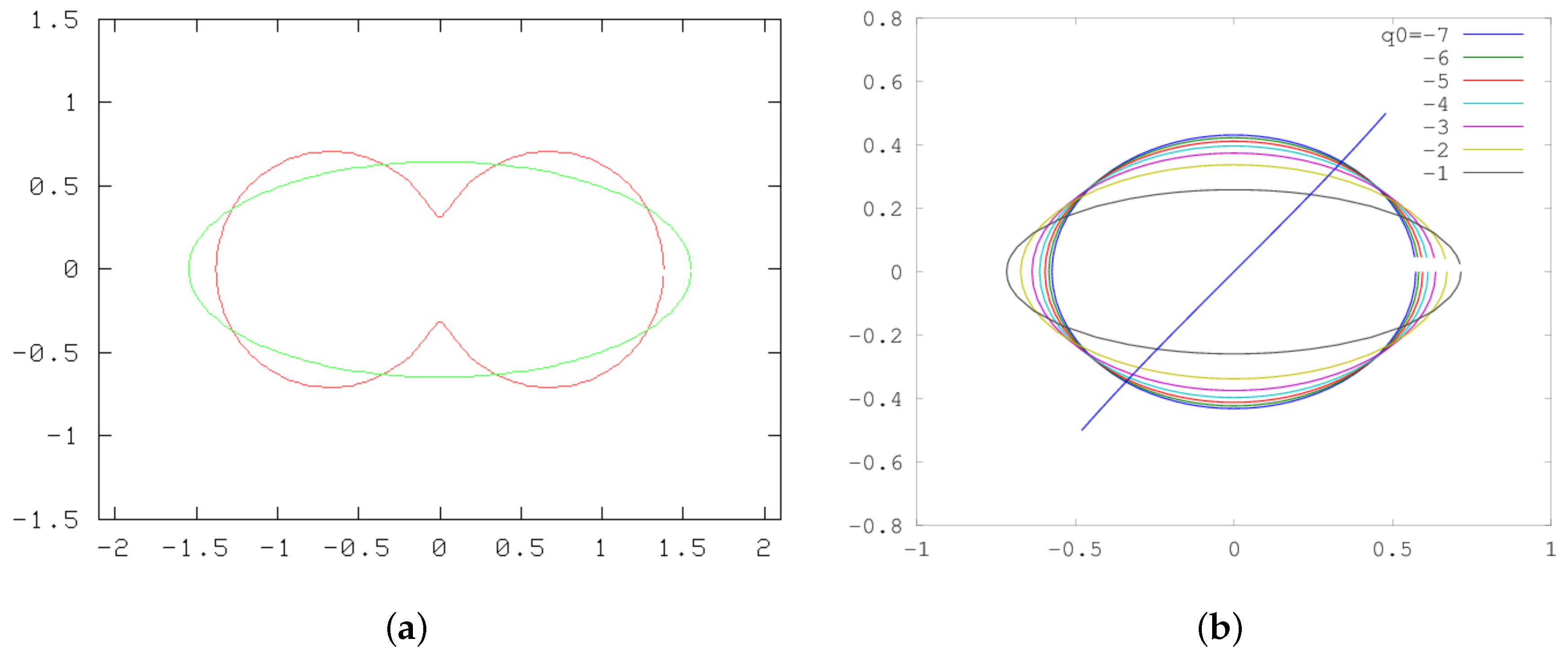
Figure 2 depicts two results for this case. Figure 2a shows an initial “dog bone” state relaxing to the Kirckhoff ellipse. In Figure 2b a background linear shear flow has been added to the Hamiltonian functional (see [24]) and the relaxation to a variety of Moore and Saffman [25] ellipses—the steady version of Kida ellipses [26]—are obtained.

5.4. Application to Jovian Vortices

Let us now describe how the formalism can be used to calculate Jovian vortices. For the modified dynamics of (36), vortex states will depend on the strength of the anomaly, q 0 , the initial radius, r 0 with A = π r 0 2 , and the initial center latitude y 0 . We use Ψ = cos ( y ) and let the procedure determine what the changes in c and U 1 need to be in order to have a steady equilibrium. We will use the linear momenta as Dirac constraints, which to within a sign are C 1 = x q ˜ and C 2 = y q ˜ . The DBSA routine then makes
[ cos ( y ) + ψ + a 1 x + a 2 y , q ˜ ] = 0 .
For this case the integral conditions (cf. Section 4.2) are obtained by multiplying (51) by y and x and integrating, yielding respectively
d x y [ a 1 x + a 2 y , q ˜ ] = a 1 d x q ˜ = d x y [ cos ( y ) + ψ , q ˜ ] = d x q ˜ x ψ = 0 d x x [ a 1 x + a 2 y , q ˜ ] = a 2 d x q ˜ = d x x [ cos ( y ) + ψ , q ˜ ] = d x sin ( y ) q ˜ + q ˜ y ψ = d x sin ( y ) q ˜ .
Consistent with symmetry, a 1 will be zero; comparing the second condition for a vortex patch of area A to the integral constraint of (33) of Section 4.3 gives
a 2 = c U 1 .
To match with the expressions from the full model, according to (29) this would need to be a 2 = [ β + F ( U 1 U 2 ) ] / α (or β in the linear jet case with U 1 = U 2 and α = 1 ), but that will generally not be the case. The DBSA algorithm will give c ( q 0 , A , y 0 ) ; we can adjust y 0 so that this agrees with the value stipulated by the far-field requirement. We shall simply look at the inverse problem: examining β ( q 0 , A , y 0 ) .

6. Results

6.1. CD–DBSA

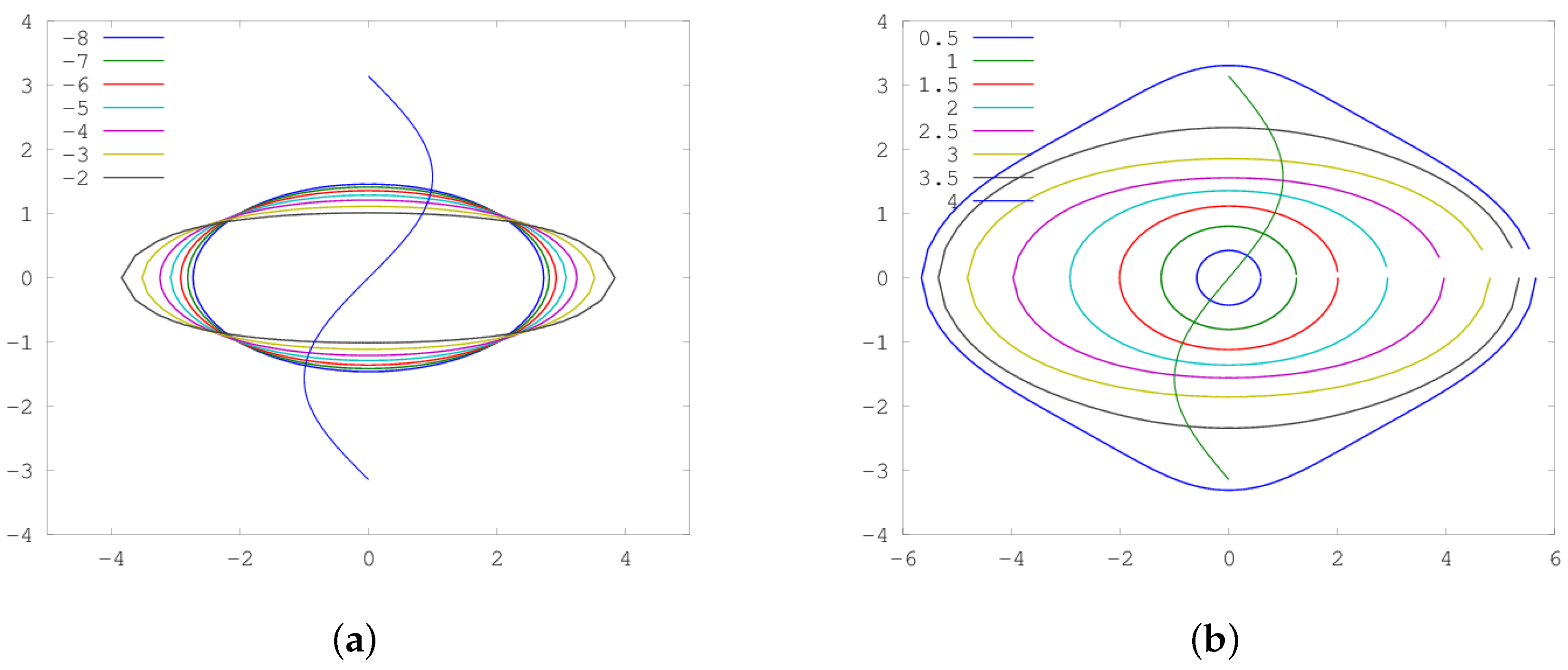
We first concentrate on the case in which the background flow does not vary with depth, U 1 = U 2 = 0 , D = 1 so that α = 1 (cf. (27), (28), and (29)). When β = 0 , the vortex center resides at y = 0 where the background flow changes sign, and it is symmetric both east-west and north-south as depicted in Figure 3. Observe in Figure 3a that it elongates as | q 0 | decreases.
In Figure 3b where the size increases, the vortex becomes visibly different from an exact ellipse, since it feels the changes in the shear. It is known that the Moore and Saffman [25] ellipse in uniform shear (the steady version of Kida’s solution [26]) has a smaller radius of curvature at the north and south for weaker shears relative to q 0 ; similarly, the solutions of Figure 3b have more curvature where the shear is small.
Although the solutions of Figure 3 were obtained using the full DBSA algorithm with Dirac constraints C 1 , 2 being the x and y moments, they could equally well be found by just applying SA; unlike the Kirchhoff ellipse [27] above which would, in the absence of the Dirac constraints, become circular. Essentially, the background shear locks in the position and orientation, with the amplitudes a i remaining zero throughout because of the symmetry. However, when we consider β 0 this is no longer the case and the constraints become critical.
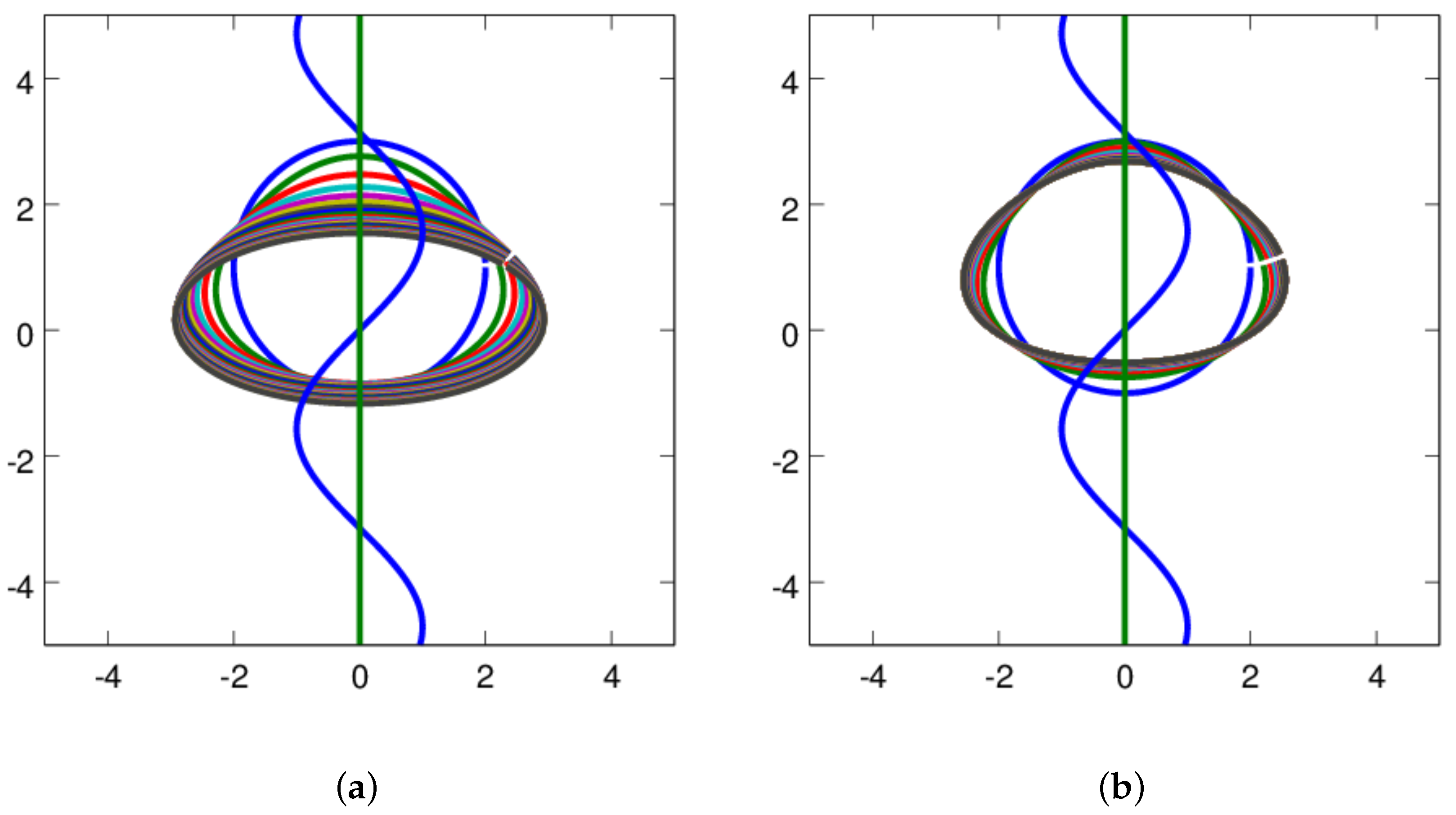
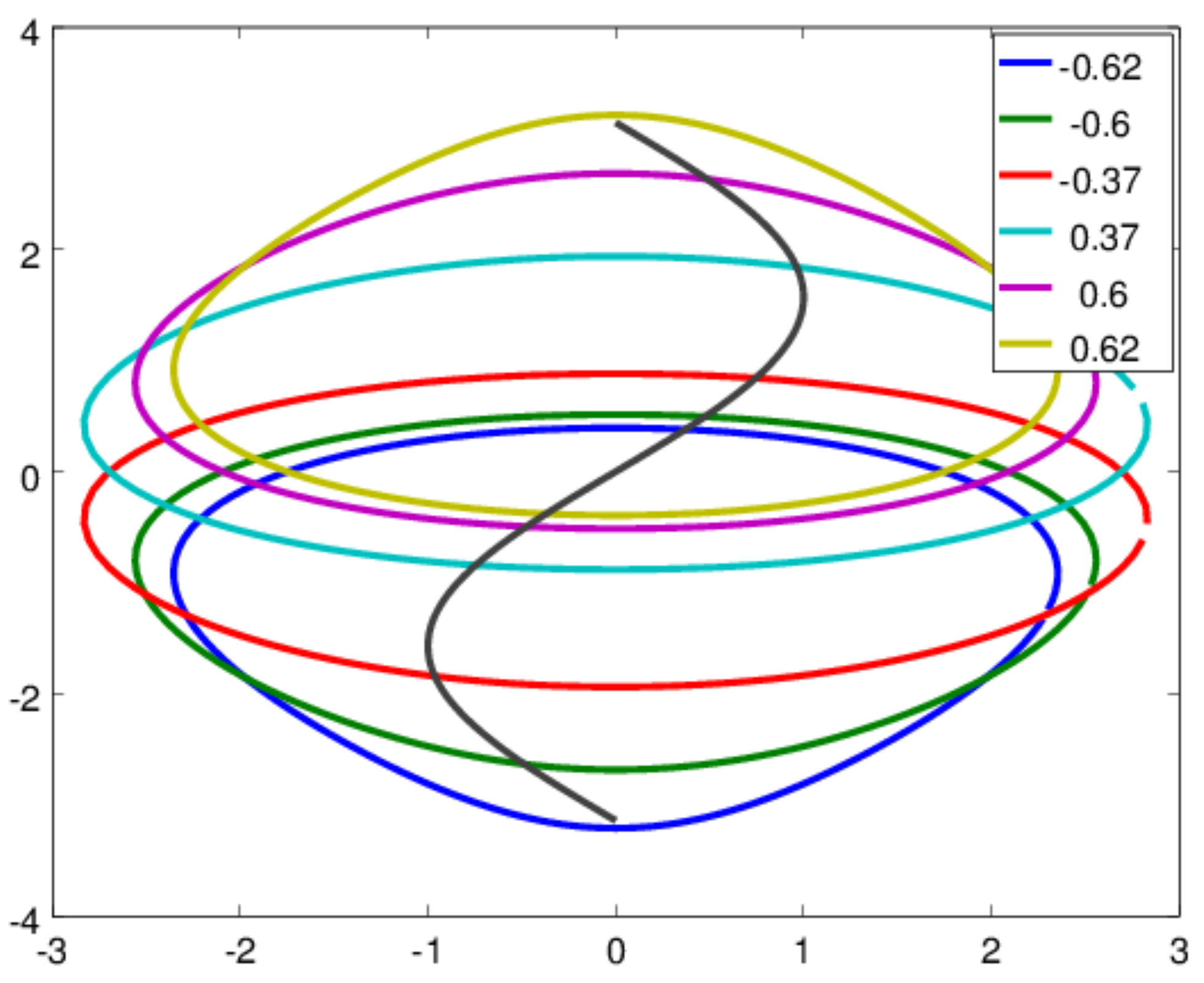
For the β 0 case, as mentioned in Section 5.4, we solve this problem in reverse by starting with a vortex centered at y = y 0 . Figure 4a shows that the standard synthetic annealing process moves this down to the y = 0 axis of symmetry and then reverts to the solution in Figure 3. In contrast, the constrained solution, Figure 4b, remains centered at y 0 in the sense that the integral d x q y is conserved; this is because that is built into the Dirac bracket as C 2 . When the solution settles, we now have a finite value of a 2 , which depends on the offset y 0 and which then determines the compatible value of β = α a 2 . Figure 5 shows a set of shapes and the corresponding β values. As β increases, the vortex resides further off the axis and has more of the m = 3 triangular mode.
Jupiter’s Great Red Spot is, of course, in the southern hemisphere, so the sense of circulation for an anticyclone is reversed. So we can take the β = 0.6 solution in Figure 5 and reverse the direction of the shear flow and the vortex circulation; the result has a slightly triangular shape pointing towards the equator with relatively rapid westward flow around the north side. These features can be seen in the Red Spot.

6.2. Comparison with Continuous Case

For the continuous version (see [28]), with β = 0 , DBSA is used directly on the original Equations (3) and (4) using a 512 2 doubly-periodic, pseudospectral QG model. The initial condition has sinusoidal zonal flows and a vortex represented by
q = exp ( [ r / r 0 ] 4 ) .
Because of the periodicity, the constraints are tapered to make them periodic at the boundaries, e.g.,
C 2 = 3 π 3 π d x q x 1 e 5 ( x 3 π ) 1 e 5 ( x + 3 π )
but otherwise the approach follows that in Ref. [9].
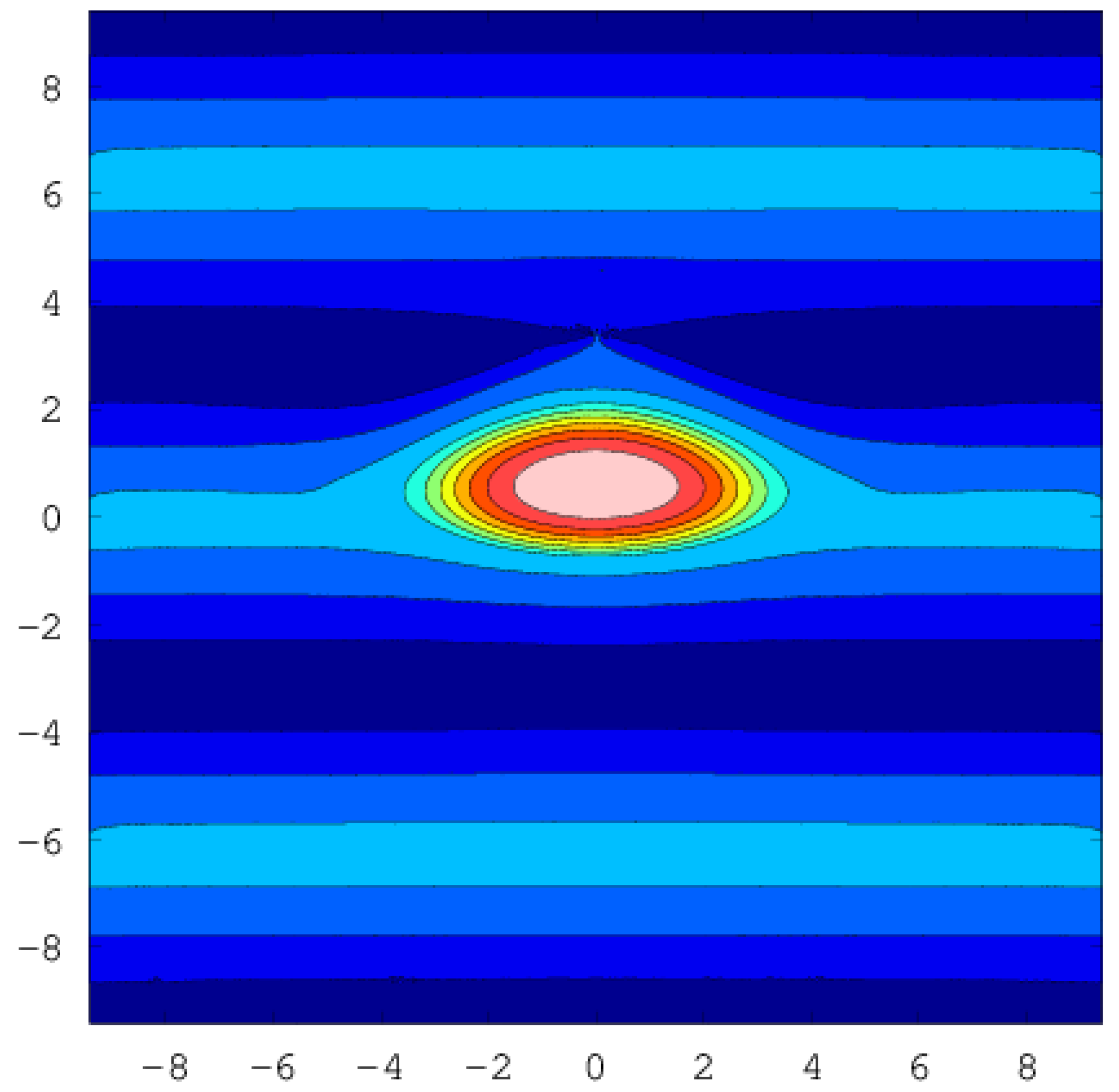
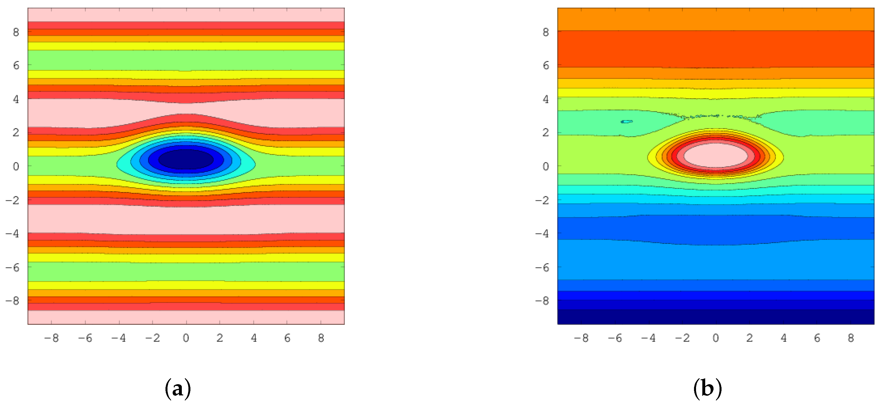
The case with the vortex centered is fairly straightforward, and gives solutions looking very similar to the CD solutions. Figure 6 shows an off-centered case with y 0 = 1 . We have used a southern hemisphere situation, consequently, the signs of the cos ( y ) and q 0 terms are reversed. The estimated phase speed is c = 0.575 .
When we include the beta-effect, the standard DBSA procedure works less well, perhaps because, at least initially, it tries to generate a net north-south flow which is problematic with the β v term. So we have taken a somewhat different tack: we solve the modified dynamics problem to find a steady state ( α = 1 )
[ ψ 0 cos y + c y , q 0 ] = 0 , q 0 = ( 2 F + 1 ) ψ 0
with the propagation speed c = q 0 sin y / q 0 . This can be rewritten by adding and subtracting cos y + c y as
[ ψ 0 cos y + c y , ( 2 F ) ψ 0 + cos y c y ] = 0
or, if we chooses β = c
[ ψ 0 cos y , q ] = β x q q = ( 2 F ) ψ 0 + cos y + β y ] = ( 2 F ) ( ψ 0 cos y ) F cos y + β y .
Thus, if we use as an initial condition the ψ 0 found from DBSA applied to the modified dynamics, the resulting structure should propagate at a speed c = β .
The q 0 field is fairly similar, while the ψ fields, as seen in Figure 7 are virtually indistinguishable. It shows the rapid flow crossing north of the vortex, with some more northerly streamlines turning back and merging into the jet above. These features, along with the asymmetric bulge to the north, are noticeable in the movies of the flow near the Red Spot.

7. Summary and Conclusions

We have studied the 1 3 4 layer model with deep sinusoidal jets and a vortex in the upper layer. The criterion for the stability of the upper layer jets, which are free to move relative to the deep flow, is that the scale of the jets (in the sense of the inverse of the wavenumber) must be larger than the deformation radius. This is also the necessary condition for isolated vortices to exist within the upper layer. In the absence of deep flow, the jets are not stable and the condition for isolated vortices cannot hold. Thus, the model argues that the long-lived vortices will be relatively shallow compared to the jets.
Using a Hamiltonian formulation of contour dynamics and synthetic annealing, we constructed vortex patch solutions in the sinusoidal flow in the absence of β . These are centered on the line where the shear flow has u = 0 . Because of the deformation radius and the variations in shear, these are not precisely elliptical in contrast to the Moore and Saffman [25] case.
With β , the shape-preserving vortices will no longer be centered and will propagate. To be able to apply the synthetic-annealing procedure, we introduced a modified form of the dynamics which has the same steady solutions but evolves according to (36). It should be noted that this procedure no longer preserves the potential vorticity on each particle as they are rearranged. But the final solution is a valid steady state and shows that the vortex is now off-center and asymmetrical. It has a triangular component reminiscent of the Red Spot.
Physically, there are, of course, other processes acting in the Jovian atmosphere. We have used a quasi-geostrophic model, which can become inaccurate in regions with high Rossby number or, perhaps more appropriately for large baroclinic vortices, with changes in thickness between isopycnals that are not small compared to the mean thickness. The deep layer is not necessarily completely steady. This can lead to radiation of waves that drain energy from the spot; however, estimates of the rate from full two-layer calculations with the two-beta model [12] suggest it is very slow. Observations show that eastward jets are sharper and narrower than westward jets, unlike our simpler sinusoidal profile. The stability analysis and conditions for isolated vortices in Section 3 do not rely on this assumption; the numerical simulated annealing approach should allow exploration of how such asymmetries affect vortex shape. Mergers with small spots may spin the large spots back up so that they can be maintained. The processes that maintain the deep jets remain unclear, but convection, moist convection, and baroclinic instability may all play a role. Despite the many unknowns, we believe that implications of the simple model—the shallow spots and the -induced asymmetries—remain valid.

Author Contributions

Conceptualization, G.R.F., P.J.M. and R.V.S.; formal analysis, G.R.F. and P.J.M.; investigation, R.V.S.

Funding

This research was supported by the U.S. Department of Energy Contract DE-FG05-80ET-53088 (P.J.M.) and the National Science Foundataion. grant OCE-1459702 (G.R.F.)

Acknowledgments

The authors warmly acknowledge the hospitality of the GFD summer program.

Conflicts of Interest

The authors declare no conflict of interest. The funders had no role in the design of the study; in the collection, analyses, or interpretation of data; in the writing of the manuscript, or in the decision to publish the results.

References

  1. Maxworthy, T.; Redekopp, L.G. A solitary wave theory of the great red spot and other observed features in the Jovian atmosphere. Icarus 1976, 29, 261–271. [Google Scholar] [CrossRef]
  2. Marcus, P.S. Numerical simulation of Jupiter’s Great Red Spot. Nature 1988, 331, 693–696. [Google Scholar] [CrossRef]
  3. Dowling, T.E.; Ingersoll, A.P. Jupiter’s Great Red Spot as a shallow water system. J. Atmos. Sci. 1989, 46, 3256–3278. [Google Scholar] [CrossRef]
  4. Williams, G.P. Jovian Dynamics. Part 1: Vortex Stability, Structure, and Genesis. J. Atmos. Sci. 1996, 53, 2685–2734. [Google Scholar] [CrossRef] [Green Version]
  5. Morrison, P.J. Poisson Brackets for Fluids and Plasmas. AIP Conf. Proc. 1982, 88, 13–46. [Google Scholar]
  6. Morrison, P.J. Hamiltonian Description of the Ideal Fluid. Rev. Mod. Phys. 1998, 70, 467–521. [Google Scholar] [CrossRef]
  7. Morrison, P.J. Hamiltonian and Action Principle Formulations of Plasma Physics. Phys. Plasmas 2005, 12, 058102. [Google Scholar] [CrossRef]
  8. Vallis, G.K.; Carnevale, G.; Young, W.R. Extremal Energy Properties and Construction of Stable Solutions of the Euler Equations. J. Fluid Mech. 1989, 207, 133–152. [Google Scholar] [CrossRef]
  9. Flierl, G.R.; Morrison, P.J. Hamiltonian-Dirac Simulated Annealing: Application to the Calculation of Vortex States. Physica D 2011, 240, 212–232. [Google Scholar] [CrossRef]
  10. Stamp, A.P.; Dowling, T.E. Jupiter’s Winds and Arnol’d’s Second Stability Theorem: Slowly Moving Waves and Neutral Stability. J. Geophys. Res. 1993, 98, 18847–18855. [Google Scholar] [CrossRef]
  11. Kaspi, Y.; Flierl, G.R. Formation of Jets by Baroclinic Instability on Gas Planet Atmospheres. J. Atmos. Sci. 2007, 64, 3177–3194. [Google Scholar] [CrossRef]
  12. Yano, J.I.; Flierl, G.R. Jupiter’s Great Red Spot: Compactness Condition and Stability. Annales Geophysicae 1994, 12, 1–18. [Google Scholar] [CrossRef]
  13. Pedlosky, J. Geophysical Fluid Dynamics; Springer: New York, NY, USA, 1987. [Google Scholar]
  14. Dirac, P. Generalized Hamiltonian dynamics. Can. J. Math. 1950, 2, 129–148. [Google Scholar] [CrossRef]
  15. Morrison, P.J.; Lebovitz, N.R.; Biello, J. The Hamiltonian Description of Incompressible Fluid ellipsoids. Ann. Phys. 2009, 324, 1747–1762. [Google Scholar] [CrossRef]
  16. Chandre, C.; Morrison, P.J.; Tassi, E. On the Hamiltonian formulation of incompressible ideal fluids and magnetohydrodynamics via Dirac’s theory of constraints. Phys. Lett. A 2012, 376, 737–743. [Google Scholar] [CrossRef]
  17. Balmforth, N.J.; Morrison, P.J. Hamiltonian Description of Shear Flow. In Large-Scale Atmosphere-Ocean Dynamics 2: Geometric Methods and Models; Norbury, J., Roulstone, I., Eds.; Cambridge University Press: Cambridge, UK, 2001. [Google Scholar]
  18. Hirota, M.; Morrison, P.J.; Hattori, Y. Variational Necessary and Sufficient Stability Conditions for Inviscid Shear Flow. Proc. R. Soc. A 2014, 470, 20140322. [Google Scholar] [CrossRef]
  19. Hagstrom, G.; Morrison, P.J. Continuum Hamiltonian Hopf Bifurcation II. In Nonlinear Physical Systems—Spectral Analysis, Stability and Bifurcations; Kirillov, O., Pelinovsky, D., Eds.; Wiley: Hoboken, NJ, USA, 2014. [Google Scholar]
  20. Roberts, K.V.; Christiansen, J.P. Topics in computational fluid mechanics. Comput. Phys. Commun. 1972, 3, 14–32. [Google Scholar] [CrossRef]
  21. Zabusky, N.J.; Hughes, M.H.; Roberts, K.V. Contour dynamics for the Euler equations in two dimension. J. Comput. Phys. 1979, 30, 96–106. [Google Scholar] [CrossRef]
  22. Noether, E. Invariante Varlationsprobleme. Nachrichten von der Gesellschaft der Wissenschaften zu Göttingen, Mathematisch-Physikalische Klasse 1918, 2, 235–257. [Google Scholar]
  23. Deem, D.S.; Zabusky, N.J. Vortex Waves: Stationary “V States”, Interactions, Recurrence, and Breaking. Phys. Rev. Lett. 1978, 40, 859–862. [Google Scholar] [CrossRef]
  24. Meacham, S.P.; Morrison, P.J.; Flierl, G.R. Hamiltonian moment reduction for describing vortices in shear. Phys. Fluids 1997, 9, 2310–2328. [Google Scholar] [CrossRef] [Green Version]
  25. Moore, D.W.; Saffman, P.G. Structure of a line vortex in an imposed strain. In Aircraft Wake Turbulence and Its Detection; Olsen, J.A., Goldburg, A., Rogers, M., Eds.; Plenum: New York, NY, USA, 1971; pp. 339–354. [Google Scholar]
  26. Kida, S. Motion of an elliptic vortex in a uniform shear flow. J. Phys. Soc. Jpn. 1981, 50, 3517. [Google Scholar] [CrossRef]
  27. Kirchhoff, G. Vorlesungen über Mathematische Physik, Mechanik c.XX; Teubner: Leipzig, Germany, 1867. [Google Scholar]
  28. Swaminathan, R.V. Vortices in Sinusoidal Shear, with Applications to Jupiter. Master’s Thesis, MIT, Cambridge, MA, USA, 2016. [Google Scholar]
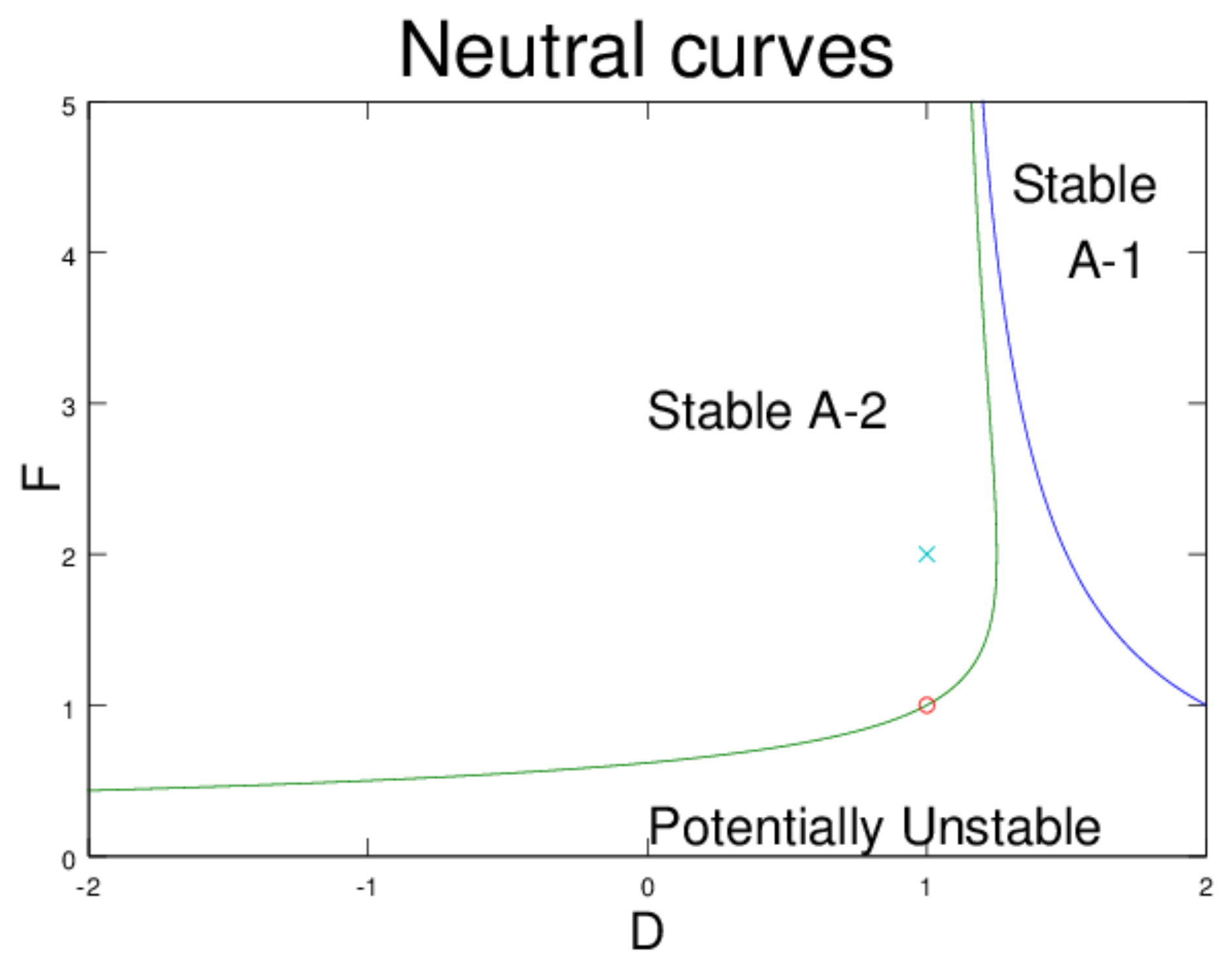
Figure 1. Regimes that are stable, based on F [ q ] being positive definite (marked A-1) or negative definite (marked A-2). Most of the derivations and simulations take the deep and shallow jets to match ( D = 1 ). The symbol × indicates the standard values D = 1 , F = 2 , well above the transition to stability at F = 1 , marked by ∘.
Fluids 04 00104 g001
Figure 2. DBSA for contour dynamics with the two constraints L and K of (42) and (44), respectively. (a) Relaxation to the elliptical V-state with 2-fold symmetry (Kirchhoff ellipse). (b) Relaxation to an elliptical state in the presence of shear (Kida ellipse) for various anomalies q 0 .
Fluids 04 00104 g002
Figure 3. DBSA with the two x and y moments taken as Dirac constraints. (a) Vortex shape as a function of q 0 from 8 to 2 . The jet vorticity is 1 at the centerline and the area is fixed at 4 π 2 . (b) Vortex shape as a function of area defined by the initial radius r 0 from 0.5 to 4. The PV anomaly is q 0 = 6 .
Fluids 04 00104 g003
Figure 4. Depiction of the evolution from a circular patch with (a) SA vs. (b) DBSA. Initially the patch is off axis (the y value being where the background flow U is antisymmetrical). Whereas SA moves it towards the axis, DBSA tries to find the distorted shape at that center.
Fluids 04 00104 g004
Figure 5. Vortex shape as a function of β , with q 0 and the area fixed. The vortex is initially centered at y 0 = 1.25 , 1 , 0.5 , 0.5 , 1 , 1.25 ; labels give the value of β (to be compared with m a x U ( y ) = 1 ) for which this would be the equilibrium solution.
Fluids 04 00104 g005
Figure 6. Potential vorticity q for a vortex centered at y = 1 . The translation speed is c = 0.575 .
Fluids 04 00104 g006
Figure 7. (a) Streamfunction for a vortex centered at y = 1 . The translation speed is c = 0.5 = β . The vortex is offset in x because it has been allowed to propagate freely for 120 time units. (b) Potential vorticity for a vortex centered at y = 1 . The translation speed is c = 0.5 = β .
Fluids 04 00104 g007