Design of a Novel μ-Mixer


Abstract
:
1. Introduction
2. Numerical Methodology
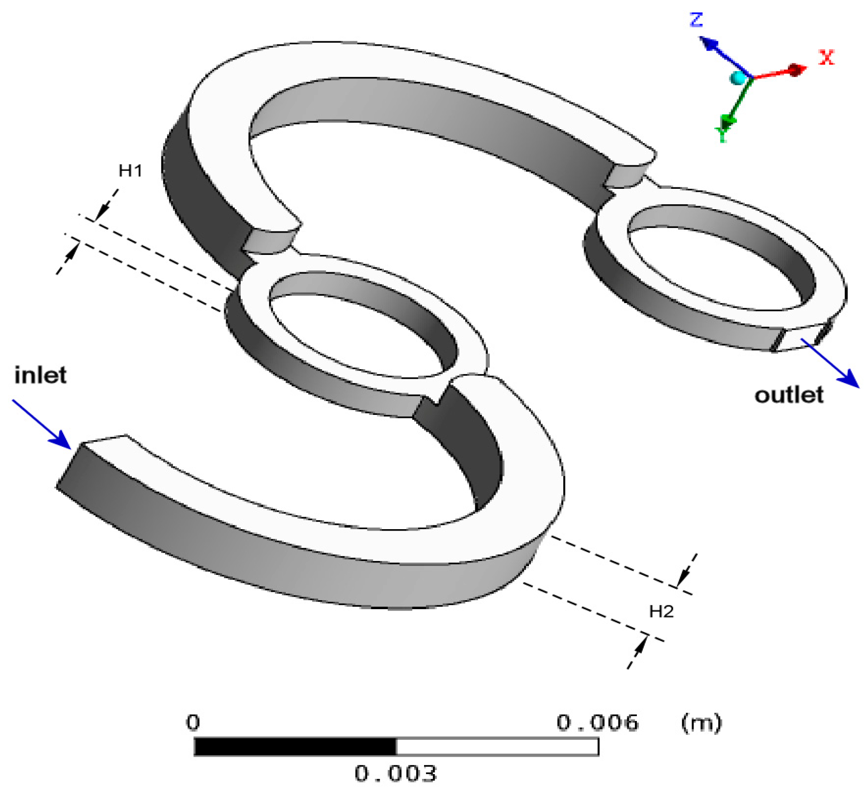
- velocities of the two fluids, on each of the two semicircles comprising the inlet,
- non-slip boundary condition at all walls,
- zero relative pressure at the outlet.
3. Results
3.1. Screening Experiments
3.2. Parametric Study
4. Conclusions
Acknowledgments
Author Contributions
Conflicts of Interest
Nomenclature
| A | cross-section of the device | mm2 |
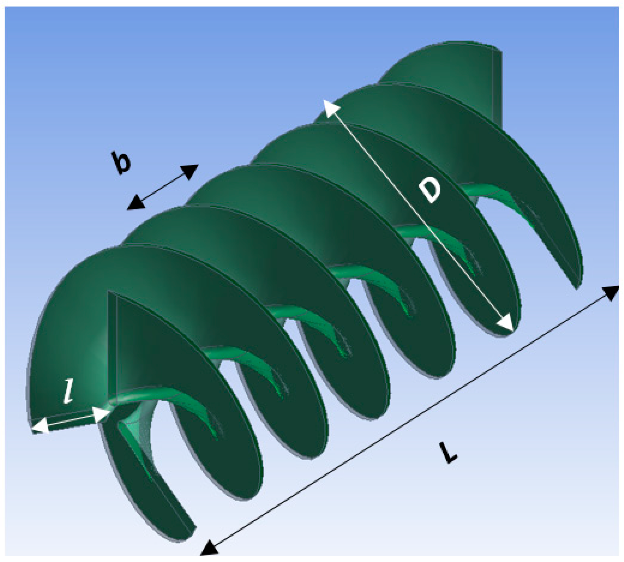
| b | blade pitch | mm |
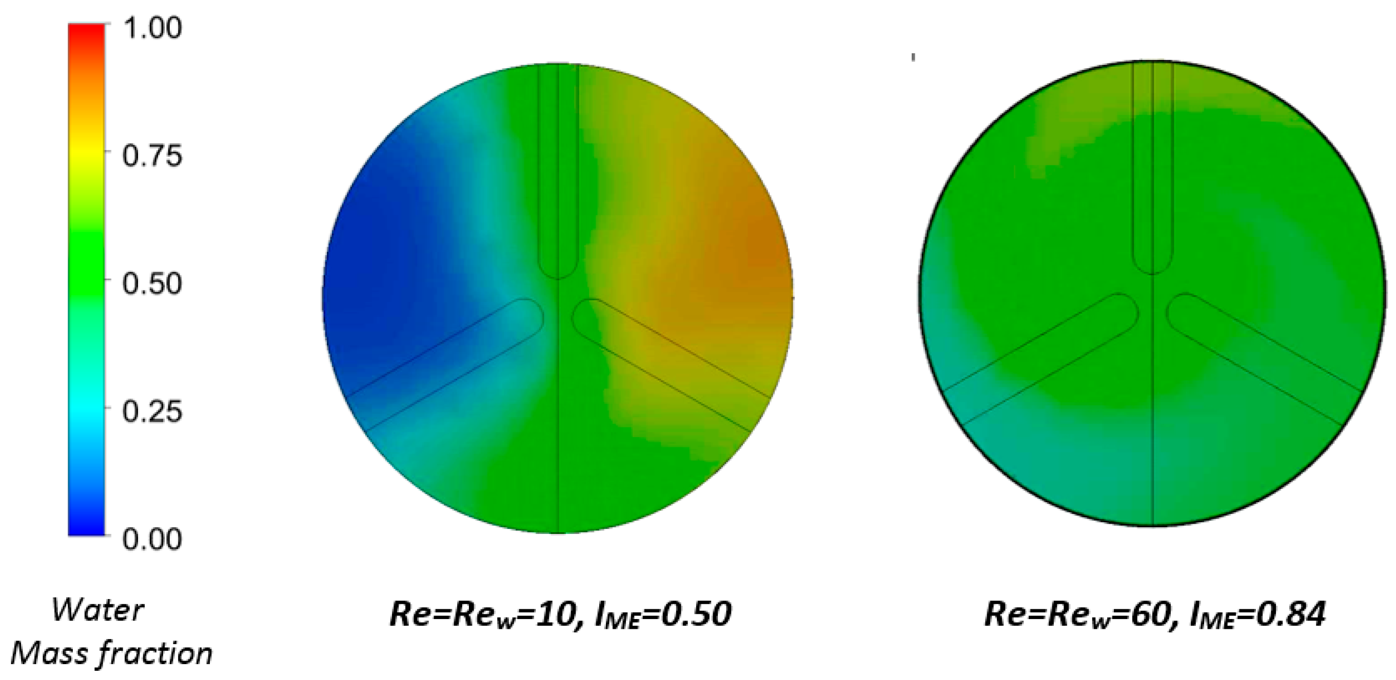
| c | mass fraction in each cell of a cross-section A | dimensionless |
| mean concentration over a cross-section A | dimensionless | |
| D | diameter of the insert | mm |
| Dm | inside diameter of the device | mm |
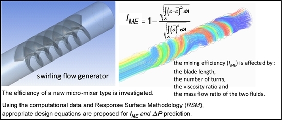
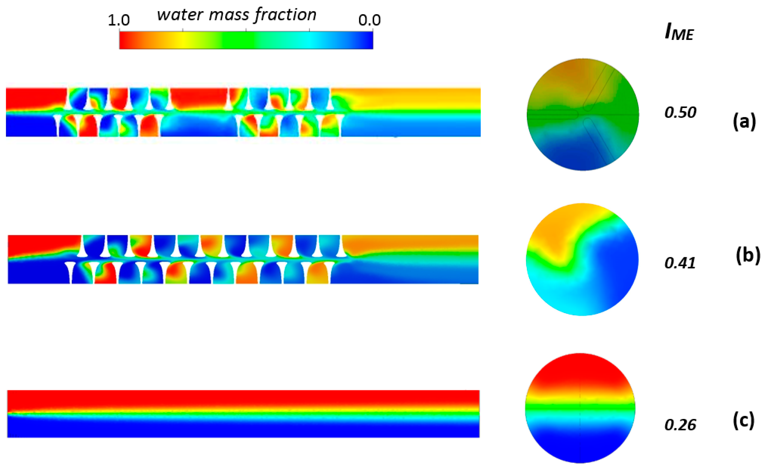
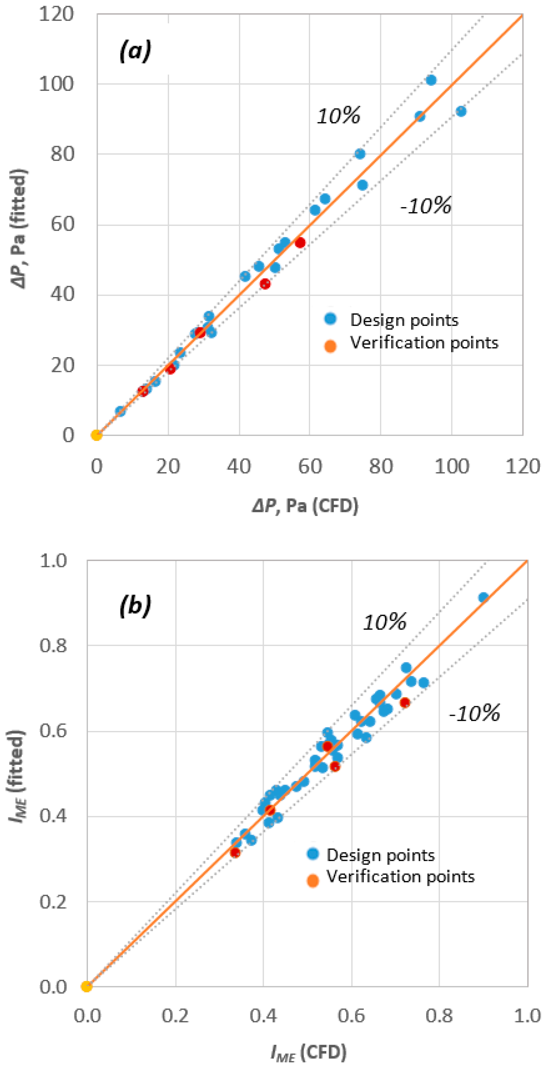
| IME | index of mixing efficiency | dimensionless |
| l | blade length | mm |
| L | length of the insert | mm |
| Lm | total length of mixer | mm |
| n | number of turns of the insert | dimensionless |
| Re | Reynolds number of each liquid based on D | dimensionless |
| ΔP | pressure drop | Pa |
| μ | liquid viscosity | Pa s |
| ρ | liquid density | kg/m3 |
| φ | angle between blade | deg |
References
- Hessel, V.; Löwe, H.; Schönfeld, F. Micromixers—A review on passive and active mixing principles. Chem. Eng. Sci. 2005, 60, 2479–2501. [Google Scholar] [CrossRef]
- Nguyen, N.-T. Micromixers—A review. J. Micromech. Microeng. 2005, 15, R1. [Google Scholar] [CrossRef]
- Hardt, S.; Drese, K.S. Passive micromixers for applications in the microreactor and μTAS fields. Microfluid. Nanofluid. 2005, 1, 108–118. [Google Scholar] [CrossRef]
- Mansur, E.A.; Ye, M. A state-of-the-art review of mixing in microfluidic mixers. Chin. J. Chem. Eng. 2008, 16, 503–516. [Google Scholar] [CrossRef]
- Kanaris, A.G.; Stogiannis, I.A.; Mouza, A.A.; Kandlikar, S.G. Comparing the mixing performance of common types of chaotic micromixers: A numerical study. Heat Transf. Eng. 2015, 36, 1122–1131. [Google Scholar] [CrossRef]
- Aref, H.; Blake, J.R. Frontiers of chaotic advection. Rev. Mod. Phys. 2017, 89, 025007. [Google Scholar] [CrossRef]
- Kanaris, A.G.; Mouza, A.A. Numerical investigation of the effect of geometrical parameters on the performance of a micro-reactor. Chem. Eng. Sci. 2011, 66, 5366–5373. [Google Scholar] [CrossRef]
- Yuan, F.; Isaac, K.M. A study of MHD-based chaotic advection to enhance mixing in microfluidics using transient three dimensional CFD simulations. Sens. Actuators B Chem. 2017, 238, 226–238. [Google Scholar] [CrossRef]
- Aref, H. The development of chaotic advection. Phys. Fluids 2002, 14, 1315–1325. [Google Scholar] [CrossRef]
- Mouza, A.A.; Patsa, C.M.; Schönfeld, F. Mixing performance of a chaotic micro-mixer. Chem. Eng. Res. Des. 2008, 86, 1128–1134. [Google Scholar] [CrossRef]
- Huang, S.-W.; Wu, C.-Y. Fluid mixing in a swirl-inducing microchannel with square and T-shaped cross-sections. Microsyst. Technol. 2017, 23, 1971–1981. [Google Scholar] [CrossRef]
- Pahl, M.H.; Muschelknautz, E. Static mixers and their applications. Int. Chem. Eng. 1982, 92, 205–228. [Google Scholar]
- Rawool, A.S.; Mitra, S.K.; Kandlikar, S.G. Numerical simulation of flow through microchannels with designed roughness. Microfluid. Nanofluid. 2006, 2, 215–221. [Google Scholar] [CrossRef]
- Versteeg, Η.Κ.; Malasekera, W. Computational Fluid Dynamics; Longman Press: London, UK, 1995. [Google Scholar]
- Box, G.E.P.; Hunter, J.S.; Hunter, W.G. Statistics for Experimenters: Design, Innovation and Discovery, 2nd ed.; J. Wiley and Sons, Inc.: Hoboken, NJ, USA, 2005. [Google Scholar]


| Parameter | Value |
|---|---|
| Total length of the mixer, Lm | 52 mm |
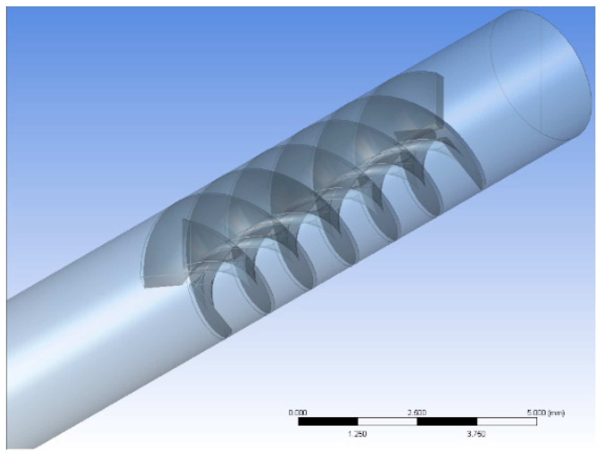
| Internal diameter of the mixer, Dm | 3.1 mm |
| Diameter of the insert, D | 3.0 mm |
| Position of the insert (distance from mixer inlet), e | 3.0 mm |
| Length of the insert, L | 7.5 mm |
| Angle between blades, φ | 120° |
| Blade length, l | 0.60–1.74 mm |
| Blade pitch, b | 0.625–2.75 mm |
| Parameter | Lower Bound | Upper Bound |
|---|---|---|
| Number of turns, n | 1 | 3 |
| Blockage ratio, l/D | 0.20 | 0.58 |
| Dynamic viscosity ratio, μ/μw | 1.0 | 20.0 |
| Density ratio, ρ/ρw | 0.6 | 1.0 |
| Inlet velocity ratio, u/uw | 1.0 | 3.0 |
| Run# | Turns, n | l/D | μ/μw | ρ/ρw | u/uw | Run# | Turns, n | l/D | μ/μw | ρ/ρw | u/uw |
|---|---|---|---|---|---|---|---|---|---|---|---|
| DP01 | 3 | 0.20 | 10.5 | 0.8 | 2 | DP22 | 2 | 0.39 | 10.5 | 0.8 | 2 |
| DP02 | 1 | 0.20 | 10.5 | 0.8 | 2 | DP23 | 2 | 0.39 | 20.0 | 0.8 | 1 |
| DP03 | 1 | 0.39 | 10.5 | 0.6 | 2 | DP24 | 2 | 0.39 | 20.0 | 0.8 | 3 |
| DP04 | 1 | 0.39 | 1.0 | 0.8 | 2 | DP25 | 2 | 0.39 | 1.0 | 1.0 | 2 |
| DP05 | 1 | 0.39 | 10.5 | 0.8 | 1 | DP26 | 2 | 0.39 | 10.5 | 1.0 | 1 |
| DP06 | 1 | 0.39 | 10.5 | 0.8 | 3 | DP27 | 2 | 0.39 | 10.5 | 1.0 | 3 |
| DP07 | 1 | 0.39 | 20.0 | 0.8 | 2 | DP28 | 2 | 0.39 | 20.0 | 1.0 | 2 |
| DP08 | 1 | 0.39 | 10.5 | 1.0 | 2 | DP29 | 2 | 0.58 | 10.5 | 0.6 | 2 |
| DP09 | 1 | 0.58 | 10.5 | 0.8 | 2 | DP30 | 2 | 0.58 | 1.0 | 0.8 | 2 |
| DP10 | 2 | 0.20 | 10.5 | 0.6 | 2 | DP31 | 2 | 0.58 | 10.5 | 0.8 | 1 |
| DP11 | 2 | 0.20 | 1.0 | 0.8 | 2 | DP32 | 2 | 0.58 | 10.5 | 0.8 | 3 |
| DP12 | 2 | 0.20 | 10.5 | 0.8 | 1 | DP33 | 2 | 0.58 | 20.0 | 0.8 | 2 |
| DP13 | 2 | 0.20 | 10.5 | 0.8 | 3 | DP34 | 2 | 0.58 | 10.5 | 1.0 | 2 |
| DP14 | 2 | 0.20 | 20.0 | 0.8 | 2 | DP35 | 3 | 0.39 | 10.5 | 0.6 | 2 |
| DP15 | 2 | 0.20 | 10.5 | 1.0 | 2 | DP36 | 3 | 0.39 | 1.0 | 0.8 | 2 |
| DP16 | 2 | 0.39 | 1.0 | 0.6 | 2 | DP37 | 3 | 0.39 | 10.5 | 0.8 | 1 |
| DP17 | 2 | 0.39 | 10.5 | 0.6 | 1 | DP38 | 3 | 0.39 | 10.5 | 0.8 | 3 |
| DP18 | 2 | 0.39 | 10.5 | 0.6 | 3 | DP39 | 3 | 0.39 | 20.0 | 0.8 | 2 |
| DP19 | 2 | 0.39 | 20.0 | 0.6 | 2 | DP40 | 3 | 0.39 | 10.5 | 1.0 | 2 |
| DP20 | 2 | 0.39 | 1.0 | 0.8 | 1 | DP41 | 3 | 0.58 | 10.5 | 0.8 | 2 |
| DP21 | 2 | 0.39 | 1.0 | 0.8 | 3 | DP42 | 2 | 0.20 | 10.5 | 0.8 | 2 |
| Parameter | ΔP | ΙΜΕ |
|---|---|---|
| α | 0.817014 | 0.026161 |
| β | 5.456162 | −1.48235 |
| γ | 0.594749 | −0.34662 |
| δ | 0.312127 | −0.18884 |
| ε | 0.72966 | −0.42494 |
| ζ | 1.472507 | −0.99062 |
| η | −0.02689 | 0.097432 |
| θ | 0.014815 | −0.16046 |
| ι | 0.126574 | 0.092324 |
| cst | 5.91789 | −0.66962 |
| Run# | Turns, n | l/D | μ/μw | ρ/ρw | u/uw |
|---|---|---|---|---|---|
| VP01 | 3 | 0.20 | 10.5 | 0.8 | 2 |
| VP02 | 1 | 0.20 | 10.5 | 0.8 | 2 |
| VP03 | 1 | 0.39 | 10.5 | 0.6 | 2 |
| VP04 | 1 | 0.39 | 1.0 | 0.8 | 2 |
| VP05 | 1 | 0.39 | 10.5 | 0.8 | 1 |
| VP06 | 1 | 0.39 | 10.5 | 0.8 | 3 |
© 2018 by the authors. Licensee MDPI, Basel, Switzerland. This article is an open access article distributed under the terms and conditions of the Creative Commons Attribution (CC BY) license (http://creativecommons.org/licenses/by/4.0/).
Share and Cite
Kanaris, A.G.; Mouza, A.A. Design of a Novel μ-Mixer. Fluids 2018, 3, 10. https://doi.org/10.3390/fluids3010010
Kanaris AG, Mouza AA. Design of a Novel μ-Mixer. Fluids. 2018; 3(1):10. https://doi.org/10.3390/fluids3010010
Chicago/Turabian StyleKanaris, Athanasios G., and Aikaterini A. Mouza. 2018. "Design of a Novel μ-Mixer" Fluids 3, no. 1: 10. https://doi.org/10.3390/fluids3010010
APA StyleKanaris, A. G., & Mouza, A. A. (2018). Design of a Novel μ-Mixer. Fluids, 3(1), 10. https://doi.org/10.3390/fluids3010010