Article

Numerical Simulation of Separation Characteristics of Particles Enhanced by Synergistic Extraction–Shearing

1
Guorui Scientific Innovation Rare Earth Functional Materials (Ganzhou) Co., Ltd., Ganzhou 341100, China
2
Jiangxi Provincial Key Laboratory of Green and Low-Carbon Metallurgy for Strategic Nonferrous Metals, College of Metallurgy Engineering, Jiangxi University of Science and Technology, Ganzhou 341000, China
3
National Engineering Research Center for Ionic Rare Earth, Ganzhou 341001, China
*
Authors to whom correspondence should be addressed.
Fluids 2026, 11(5), 126; https://doi.org/10.3390/fluids11050126
Submission received: 8 April 2026 / Revised: 14 May 2026 / Accepted: 15 May 2026 / Published: 20 May 2026

Abstract

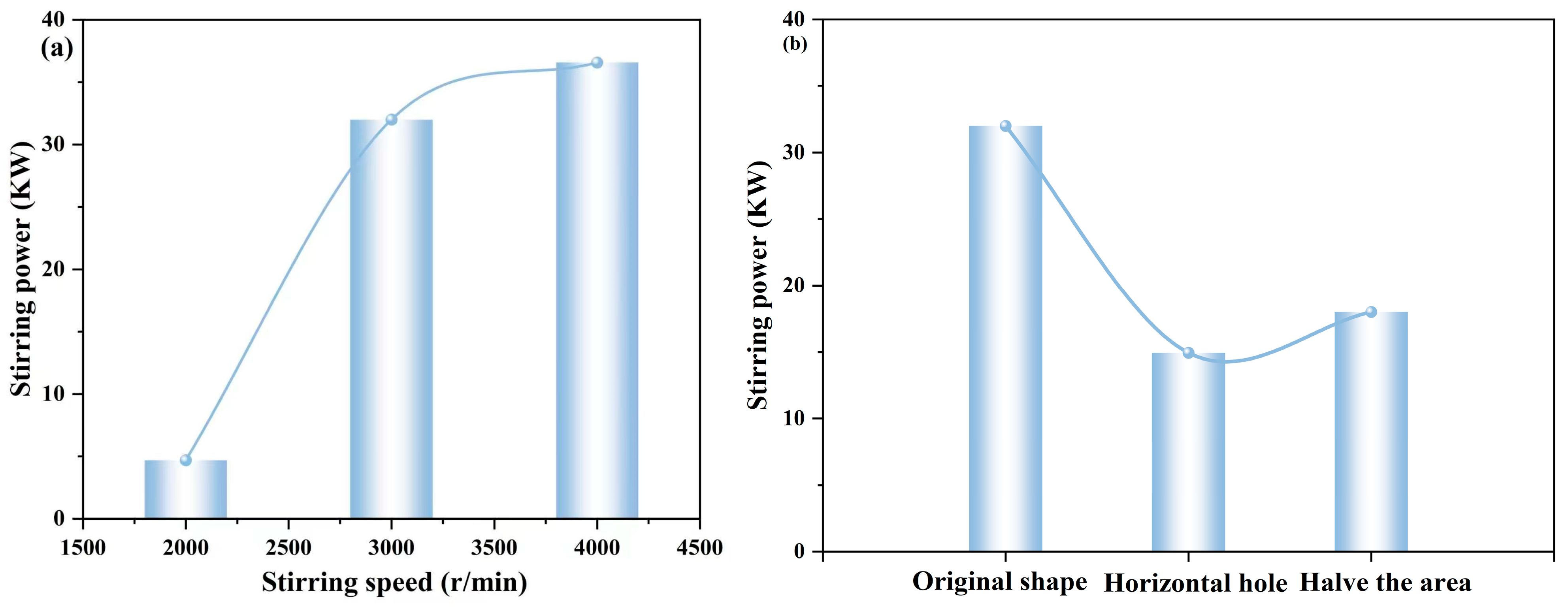
This study utilizes computational fluid dynamics (CFD), numerical simulation of particle separation characteristics enhanced by synergistic extraction–shearing is performed, and the two-phase flow in a liquid–solid stirred tank is simulated using the Eulerian–Eulerian two-fluid model and the standard k ε model. The effects of impeller speed, the hole arrangement pattern of the annular shroud, and the hole area on the multiphase fluid dynamics behavior and stirring power inside the tank are systematically studied. The results show that stirring speed is a key operating parameter affecting turbulence intensity and particle mixing uniformity. When the stirring speed increases from 2000 r/min to 4000 r/min, the overall tank turbulence increases significantly, but the stirring power increases from 4.69 kW to 36.57 kW. The annular cover at the bottom is arranged with vertical openings, which enables full energy transfer within the tank and effectively enhances the turbulence intensity in the middle and lower sections of the flow field; the horizontal opening form is more conducive to the radial diffusion of particles in the middle layer. Reducing the hole area by half increases the fluid jet velocity and local shear stress, effectively improving particle distribution uniformity, while the stirring power decreases by 43.75%, thereby achieving the collaborative optimization of mixing efficiency and energy consumption.

1. Introduction

Liquid–solid stirring equipment is widely used in industries such as petroleum, chemical, pharmaceutical, and metallurgy due to its excellent performance in homogenizing material mixing and enhancing particle suspension [1,2,3,4,5]. The complex structure of the stirring impeller and its rotational motion lead to complex quasi-periodic three-dimensional unsteady turbulence within the stirred tank. The flow field performance inside the stirred tank directly determines the mixing effect and serves as an important foundation for studying and optimizing processes such as fluid mixing, reaction, heat transfer, mass transfer, and momentum transfer within the tank. Therefore, a deep understanding of the internal flow characteristics and particle distribution patterns under various operating conditions is essential for improving mixing efficiency and reducing energy consumption.
In recent years, a multitude of researchers worldwide have optimized the design of stirring equipment in accordance with process requirements across various industries, aiming to achieve the desired stirring performance. Zhang et al. [6] perform single-factor experiments on mechanical stirring parameters and find that seeding performance is optimal at a stirring speed of 30 r/s, a ratio of stirrer length to seed box diameter of 0.69, and a spacing of 0.11 cm between the pump tube and the stirrer. Dong et al. [7] introduce a modulated electromagnetic stirring (MM-EMS) strategy and find that the optimized MM-EMS with a peak current intensity of 300 A yields equivalent performance to conventional 300 A electromagnetic stirring in reducing superheat, improving the uniformity of the solidified shell and the efficiency of inclusion removal, while exhibiting superior behavior in alleviating near-surface negative segregation. Silva et al. [8] examine the influences of propeller types (naval type and ARA-S type) and stirring speeds (180 r/min and 360 r/min) on the rheological, physicochemical and sensory properties of creamed honey in mechanical stirrers. They observe that samples stirred with naval propellers present higher apparent viscosity, emulsified honey displays pseudoplastic and liquid-like rheological behavior, and its crystalline structure possesses relatively low thermal stability. Although experimental studies reflect the macroscopic performance of stirring systems, the detailed flow structures within the internal flow field are hardly observable. Hence, in-depth investigations by means of numerical simulation are of great necessity.
CFD has proved to be a useful tool in analyzing the impact of these factors on the flow characteristics of such systems [9,10,11,12,13,14]. Montante et al. [15] investigate the application of large-blade impellers in turbulent single-phase and two-phase mixing and find that efficient turbulent two-phase mixing is achieved using large-blade impellers in baffled vessels. Xiong et al. [16] examine the power consumption, flow patterns and flow field instabilities of three systems, namely unbaffled stirred tanks, conventional baffled stirred tanks and perforated baffled stirred tanks, and reveal that the system with perforated baffles exhibits superior mixing characteristics. Wang et al. [17] propose a stirring device integrating a modified frame and propeller blades, which significantly improves mixing efficiency and thermal uniformity and greatly accelerates the esterification process. Dakshinamoorthy et al. [18] adopt the multiple reference frame (MRF) method to simulate fluid flow in a standard Rushton turbine stirred vessel, providing insights into the suppression of local runaway and runaway reactions inside the vessel under incomplete mixing conditions. Vilardi et al. [19] use computational fluid dynamics techniques to optimize the production conditions of nano-iron particles in stirred tank reactors equipped with two classical impellers: the Rushton turbine and the four-blade propeller. The results show that the optimal performance is obtained at an impeller speed of 1500 r/min, with the clearance between the Rushton turbine and the reactor wall being 0.25 times the vessel diameter, and the clearance between the four-blade propeller and the reactor wall being 0.4 times the vessel diameter. Gu et al. [20] compare the solid–liquid mixing performance of four pitched-blade impellers and fractal impellers via CFD simulation. Fractal impellers can reduce trailing vortices, lower power consumption, and improve energy efficiency and particle suspension uniformity. Performance improves with higher fractal iterations. The suitable impeller spacing is T5/6 and T. The suitable blade angles are 45° and 60°. Fractal blades are more efficient than jagged blades. Larger particles and higher solid loading lead to poorer mixing uniformity. The simulation results agree well with experimental data. Rao et al. [21] modify the conventional turbine impeller by introducing single/double rectangular and V-shaped notches and investigate the system power consumption through experiments and CFD simulations. The results demonstrate that the power consumption of double V-shaped notched blades is lower than that of rectangular notched blades. Jiang et al. [22] conduct CFD simulations of dense solid–liquid mixing in stirred tanks at 35% solid volume fraction using the Euler–Euler and standard k ε models. Multi-impeller systems exhibit better shear rate uniformity and near-complete particle off-bottom suspension than the single-impeller system, which show band-shaped particle accumulation. Multi-impeller tanks generate stronger free-surface vortices, while circumferential triangular baffles effectively suppress vortices, strengthen axial flow, eliminate bottom particle buildup, and improve mixing homogeneity, offering guidance for industrial mixing optimization. The above studies remain insufficiently in-depth. Mixing in liquid–solid stirred tanks involves fluid flow and mass transfer processes with highly complex temporal and spatial structures. Further research is therefore required to provide more effective guidance for multiphase stirring applications.
Therefore, based on computational fluid dynamics, this study employs the Eulerian–Eulerian two-fluid model to describe the flow characteristics of the liquid–solid two-phase system, and proposes a novel four-blade straight paddle agitator with an annular shroud for numerical simulation. The study systematically investigates the effects of agitation speed, hole arrangement pattern, and hole area on the turbulent kinetic energy (TKE), turbulent kinetic energy dissipation rate (TDR), Y2O3 particle volume fraction field, agitation power, agitation dead zone, and average motion velocity of Y2O3 particles within the stirred tank. This study aims to provide a theoretical basis for the synergistic enhancement of extraction and shearing and guide the structural optimization of stirring equipment and the optimization of process parameters towards high efficiency and low consumption.

2. Mathematical Model

The Eulerian multiphase flow model is adopted to describe the liquid–solid two-phase flow, in which each phase is regarded as an interpenetrating continuum, and the mass and momentum conservation equations for each phase are solved separately within the Eulerian framework. The relevant expressions are as follows:
α q ρ q t + α q ρ q u q = 0
α q ρ q u q t + α q ρ q u q u q = α q P + μ eff   , q α q u q + u q T + α q ρ q g + F inter  
where α q is the phase volume fraction, with the sum of the liquid and solid volume fractions equal to 1 (αl + αs = 1). ρ q and uq represent the density and velocity vector of phase q in the computational domain, respectively. P, μ eff , q , and g denote the fluid pressure, effective viscosity, and gravitational acceleration, respectively. The symbol Finter represents the sum of interphase interaction forces, including drag force (FD), lift force (FL), turbulent diffusion force (FTD), wall lubrication force (FWL), and virtual mass force (FVM).
F inter   = F D + F L + F T D + F W L + F V M
F D = 3 4 α s ρ l C D d p u s u l ( u s u l )
F L = C L r l ρ g u l u g × × u l
F T D = C T D 3 4 α s ρ l C D d p u s u l ν t σ t α l
F W L = max 0 , C w 1 + C w 2 d p y w α s ρ l u s u l 2 n w
F VM = C VM r g ρ l D l u l D t D g u g D t
Here, d b is the particle diameter and C D is the drag coefficient. CL is a suitable proportionality coefficient. CTD is the turbulent dispersion force coefficient, which is typically taken as 1.0. The value 0.5 for CVM holds true in the case of spherical particles and was adopted here in absence of more precise information. According to the research by Tamburini et al. [23], when the particle-to-fluid density ratio ρβα > 2, the contributions of non-drag forces can be neglected. Therefore, only the drag force is considered in the present work, and all other interphase forces are reasonably neglected.
In the Euler–Euler two-fluid model, the Gidaspow model is used for the solid-phase viscosity and the Lun-et-al model is used for the solid-phase particle pressure as suggested by Xie et al. [24].
μ s = 5 96 ρ s d s π Θ s 1 + 4 5 ( 1 + e ) g 0 α s 2
p s = α s ρ s Θ s 1 + 2 ( 1 + e ) g 0 α s
Here, μ s represents the shear viscosity of the solid phase, d s is the particle diameter, p s is the pressure of the solid-phase particles, and α s is the volume fraction of the solid phase.
According to Guha et al. [25], when the particles are approximately spherical and the particle concentration is low, the Shiller–Naumann model outperforms other models. As these conditions apply to the current study, the Shiller–Naumann model is employed here.
C D = 24 R e p ( 1 + 0.15 R e p 0.687 ) , R e p 1000 0.44 , R e p > 1000
R e p = ρ l d p u s u l μ l
According to the study of Aubin et al. [26], standard k ε has higher calculation accuracy and moderate calculation time compared to other models, so the standard k ε model is considered in this study.
The equations for the turbulent kinetic energy k and turbulent dissipation rate ε are as follows:
x i ρ k u i = x j μ + μ t σ k k x j t ( ρ k ) + G k ρ ε
x i ρ ε u i = x j μ + μ t σ ε ε x j t ( ρ ε ) + C 1 ε ε k G k C 2 ε ρ ε 2 k
μ t = ρ C μ k 2 ε
where μ t is the turbulent viscosity, and G k represents the generation of turbulent kinetic energy due to mean velocity gradients. C 1 ε , C 2 ε , σ k , σ ε , and C μ are model constants determined through fundamental turbulence experiments, with default values of 1.44, 1.92, 1.0, 1.3, and 0.09, respectively.

3. Numerical Model

3.1. Simulation Configuration

In this paper, the open source computational fluid dynamics software package OpenFOAM 7 is used to conduct numerical simulation studies.
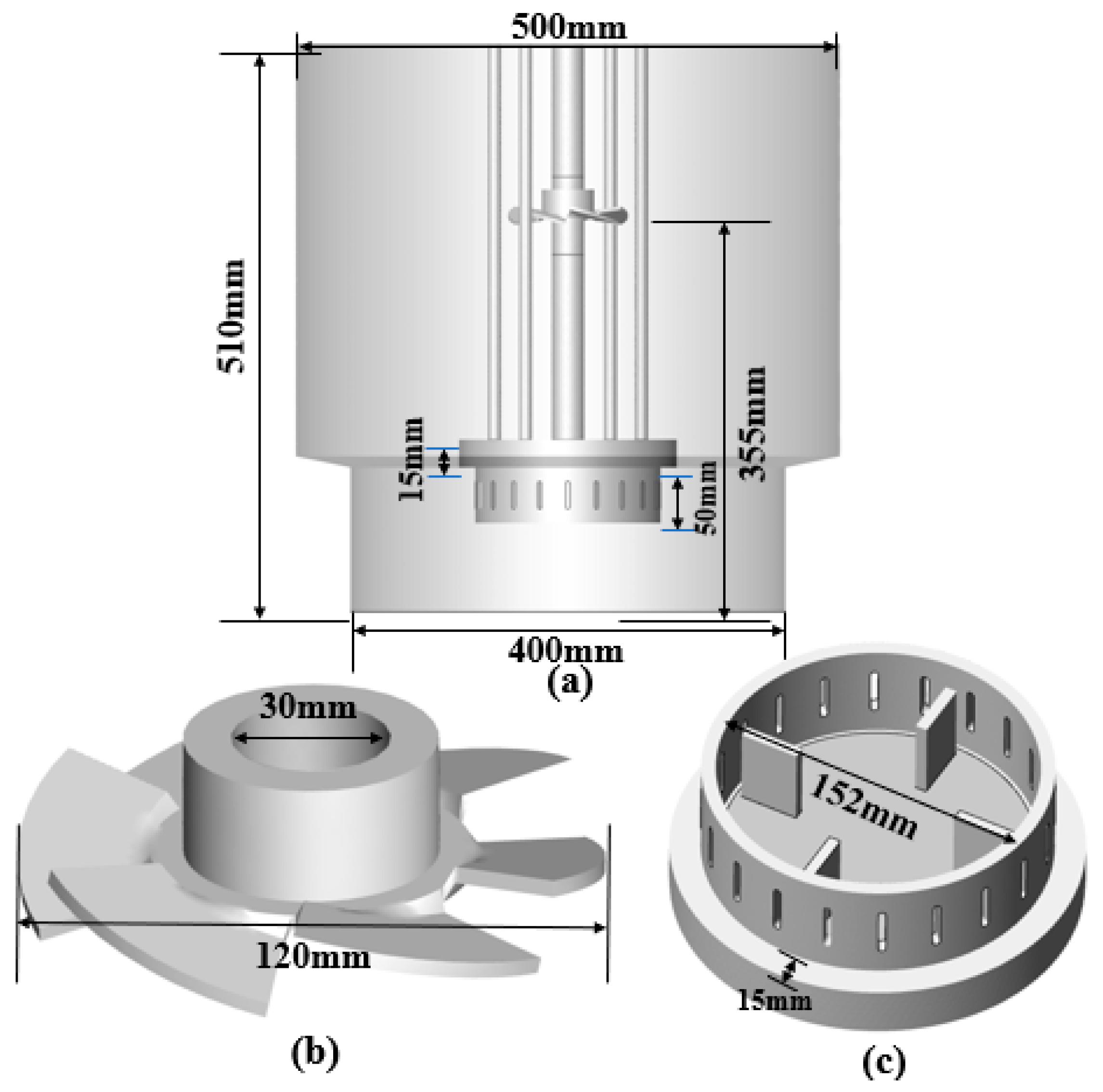
The geometric structure of the stirred tank with dual impellers is shown in Figure 1a. The stirred tank consists of two cylinders of unequal diameters, with a total height of 510 mm, an upper cylinder diameter of 500 mm, and a lower cylinder diameter of 400 mm. The stirrer shaft has a diameter of 30 mm. The upper impeller is a six-bladed axial-flow impeller (Figure 1b) with a diameter of 120 mm. The lower impeller is a four-bladed straight paddle with an annular shroud (Figure 1c). It is equipped with four support rods, giving it a total diameter of 146 mm, and the four embedded straight blades each measure 30 mm in length, 6 mm in thickness, and 40 mm in height. The annular shroud is uniformly perforated with 20 holes. The clearance between the lower impeller and the tank bottom is 100 mm, and the distance between the upper and lower impellers is 220 mm.
A yttrium-containing solution and Y2O3 particles are considered. The density of the yttrium-containing solution is 1100 kg/m3, and its viscosity is 0.0075 kg/(m·s). The density of the Y2O3 particles is 5000 kg/m3. The tank wall, impellers, and central shaft are all set to no-slip wall conditions. The multiple reference frame method is adopted to model the counterclockwise rotation of the impellers, with a rotational speed of 3000 r/min. The computational domain is divided into a stationary zone and a rotating zone, with data exchange between the two zones through an interface. The phase coupled SIMPLE algorithm is employed for pressure–velocity coupling, and the initial condition is a uniform mean solid concentration of 0.1.

3.2. Model Validation

The model validation of this study follows the research method of Zhang et al. [27].
The model employs a cylindrical mixing vessel with both a diameter and height of 400 mm, and the stirrer has a diameter of 180 mm, with the blade distance from the bottom of the vessel being 170 mm. By comparing the dimensionless velocities obtained from the simulation with the experimental data, the accuracy and reliability of the established model were verified.

3.3. Grid Validation

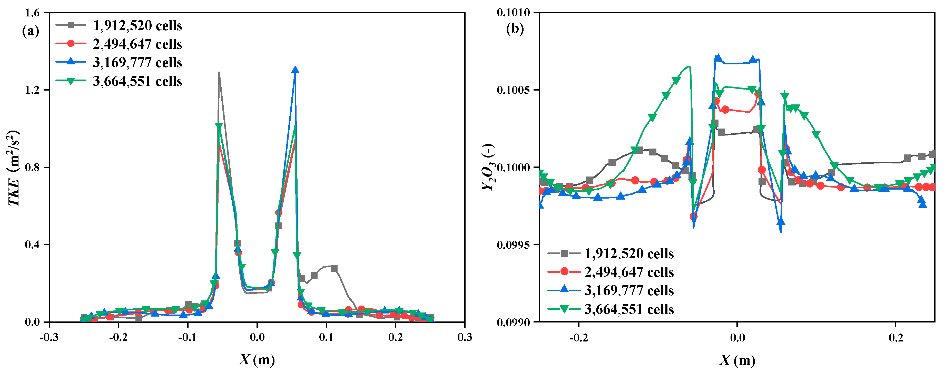
Figure 2 presents the verification of grid independence based on turbulent kinetic energy and the volume fraction of Y2O3. To assess mesh independence, four poly-hexcore grids with 1,912,520, 2,494,647, 3,169,777, and 3,664,551 cells are tested. The results show minor discrepancies between the coarser meshes (1,912,520 and 2,494,647 cells) and the finer solutions, whereas deviations for the 3,169,777 and 3,664,551 cells grids are negligible. Accordingly, the poly-hexcore mesh with 3,169,777 cells is selected for all subsequent simulations.

4. Results and Discussion

4.1. Effect of Stirring Speed

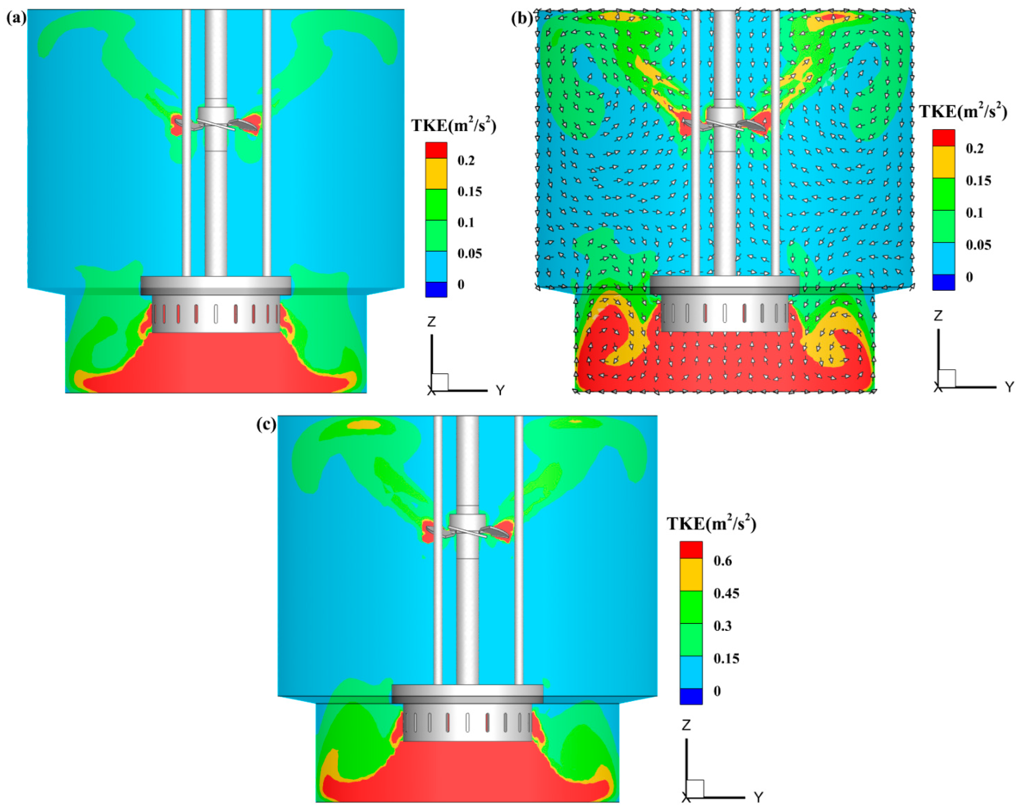
Figure 3 shows the contours of TKE distribution at different rotational speeds. Similar TKE distribution patterns are observed across the three rotational speeds. As the rotational speed is increased from 2000 r/min to 4000 r/min, the turbulent kinetic energy (TKE) in the near-impeller region and the core flow area below the impeller exhibits a substantial increase of over 200%, accompanied by a considerable expansion of the high-TKE region. This enhancement can be attributed to the intensified fluid motion resulting from the higher impeller rotational speed, which in turn strengthens the TKE. In contrast, TKE is found to decrease markedly in regions far from the impeller due to energy dissipation. Figure 3b illustrates the fluid velocity vector with arrows representing its flow direction. A radial jet is generated by the rotation of the lower impeller, which, upon impacting the tank wall, splits into upward and downward flows, leading to the formation of an upper large-scale recirculation vortex and a lower suction-type circulation vortex. This flow structure not only improves liquid–solid mixing efficiency through global circulation but also effectively prevents solid particle sedimentation by virtue of strong bottom turbulence and upward velocity.
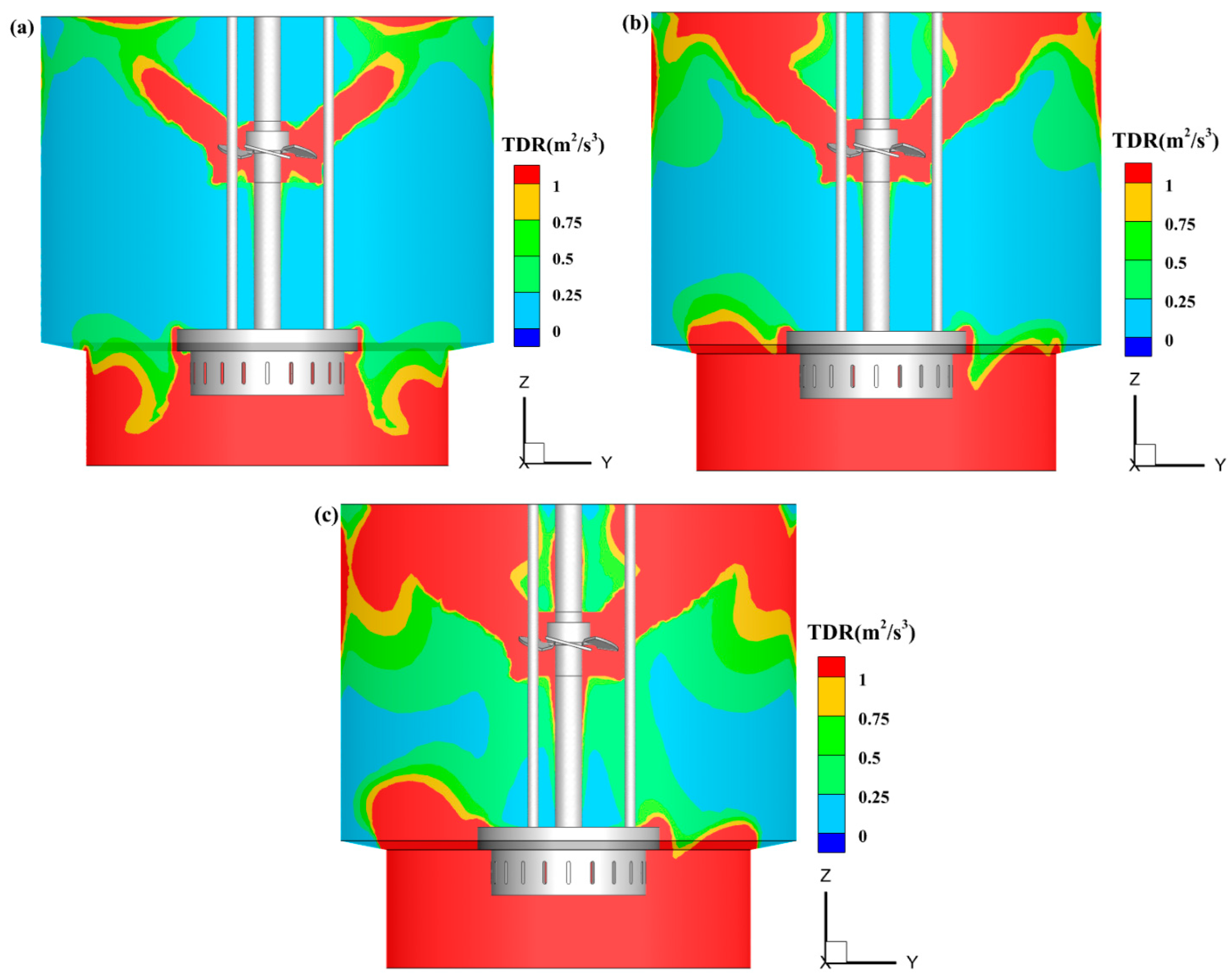
Figure 4 illustrates the contours of the TDR at different rotational speeds. TDR is a key parameter in fluid mechanics by which the rate of turbulent kinetic energy dissipation is quantified. Under all three rotational speeds, a similar overall distribution pattern is observed for TDR, with high values concentrated near the impellers and in the lower part of the tank. Moreover, TDR is found to decrease progressively from the impeller region toward the tank walls, especially in the vicinity of the upper axial-flow impeller, indicating that a stronger shear is imposed on the fluid by the lower impeller with the annular shroud compared with the upper impeller. As the rotational speed is increased, the shearing effect of the impellers is intensified and the shearing region is expanded, leading to a pronounced enhancement of TDR in the axial direction.
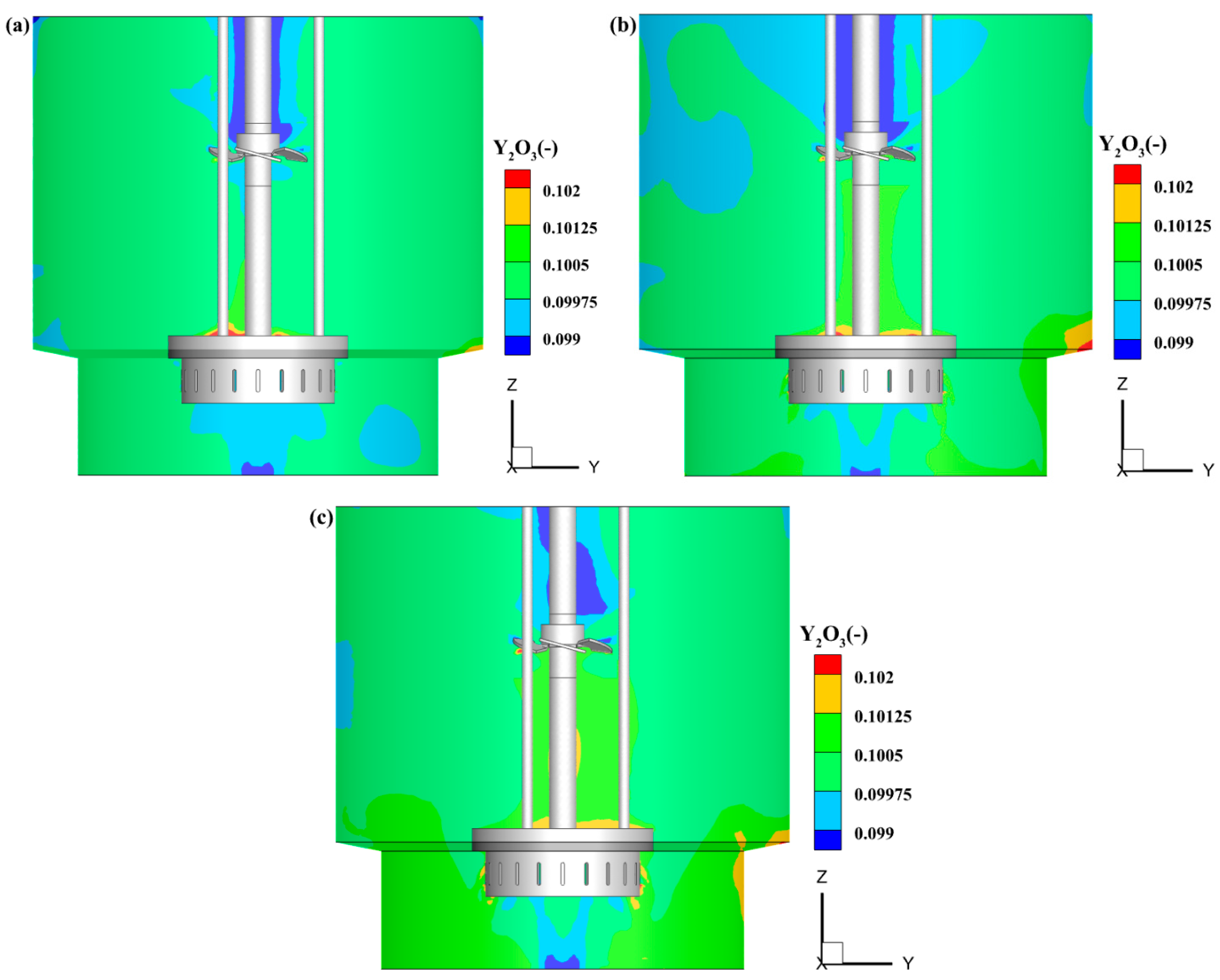
To analyze particle separation characteristics enhanced by synergistic extraction-shearing, the effect of different rotational speeds on the volume fraction of Y2O3 is displayed in Figure 5. At a low rotational speed of 2000 r/min, the volume fraction distribution of Y2O3 is highly uneven, with large dead zones where solid particles are prone to sedimentation. When the rotational speed is increased to 3000 r/min, the turbulent intensity is enhanced, resulting in a significant improvement in the uniformity of the volume fraction distribution and a substantial reduction in dead zones. At a high rotational speed of 4000 r/min, the Y2O3 volume fraction is uniformly distributed throughout the entire tank, with only slight local differences. This improvement is attributed to the increased rotational speed, which enhances TKE and fluid shear forces, effectively breaking up particle agglomerates and intensifying global circulation, thereby dispersing the solid particles more evenly throughout the mixing space.
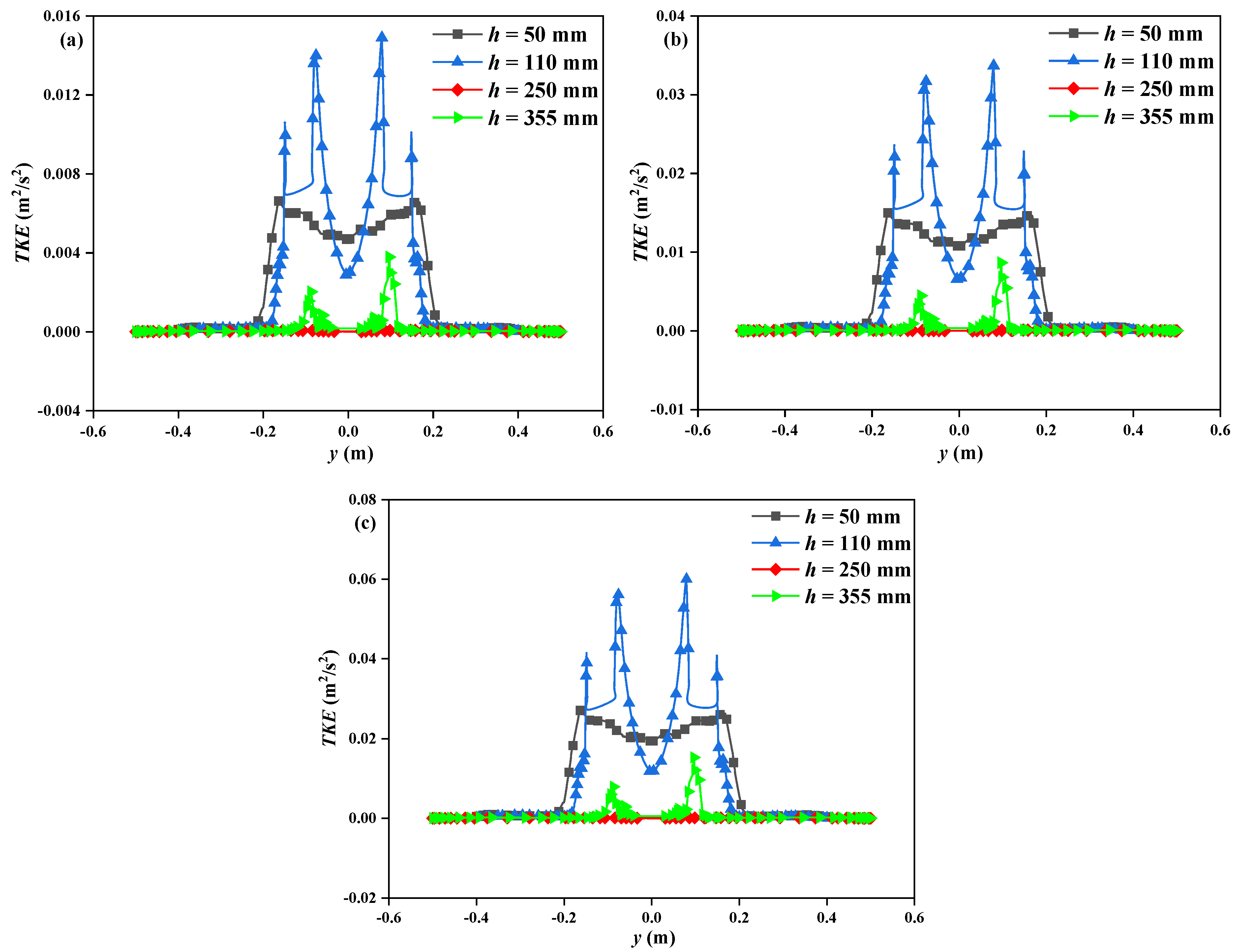
The effect of different rotational speeds on the radial distribution of TKE at different heights is shown in Figure 6. At heights of 50, 110, and 350 mm, the peak TKE increases significantly with increasing rotational speed. This is because these three heights are all located in the near-impeller region, and the increase in rotational speed promotes fluid circulation throughout the stirred tank, leading to an increase in TKE. Meanwhile, the increase in rotational speed significantly enhances TKE in the near-impeller region. It is worth noting that TKE is notably higher in the region near the center of the stirrer shaft, whereas it approaches zero in the wall region away from the stirrer shaft. This can be attributed to the rotation of the impeller directly drives fluid motion in the adjacent region and in the wall region far from the impeller, the no-slip boundary condition significantly suppresses the generation of turbulent structures, resulting in low TKE intensity.
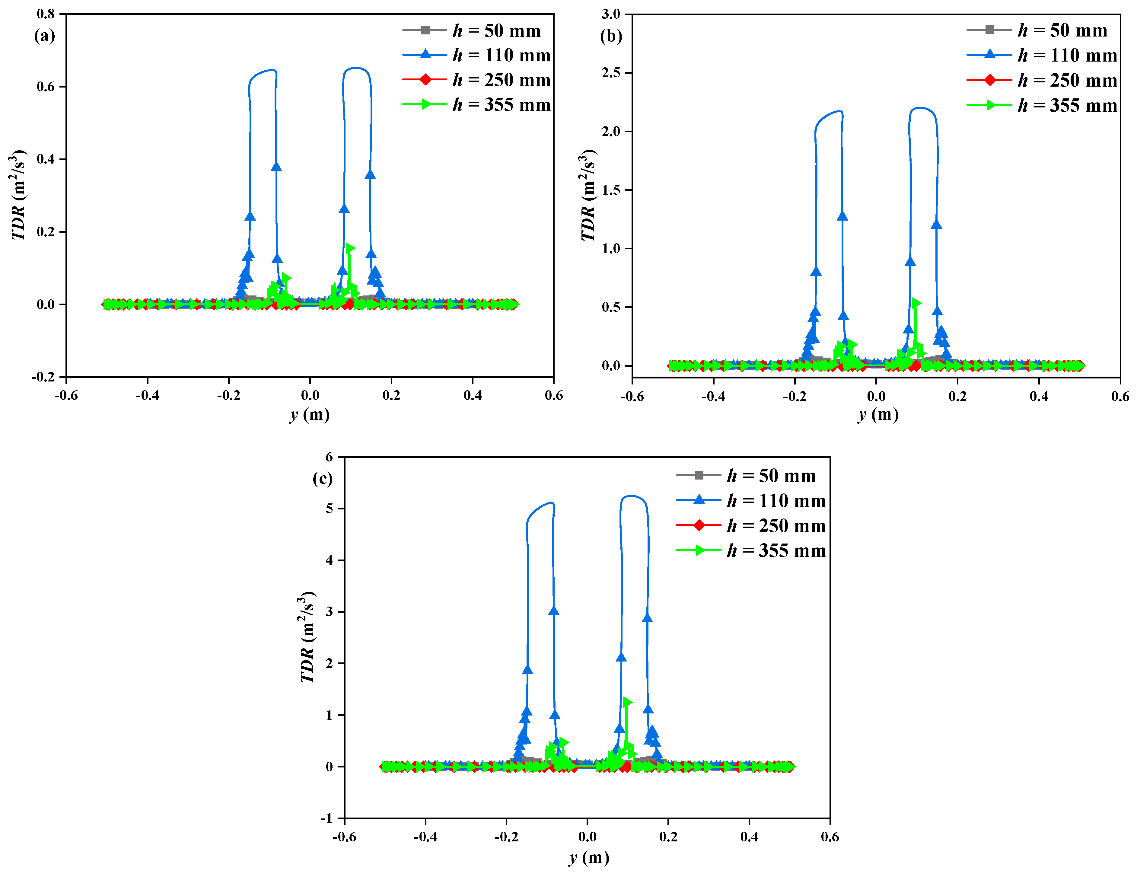
Figure 7 demonstrates the effect of different rotational speeds on the radial distribution of the TDR at different heights. At heights of 110 mm and 355 mm, distinct peaks in the TDR are observed due to the direct strong agitation of the fluid by the impellers. In contrast, in the axial regions far from the impellers, the radial distribution of the TDR is relatively uniform, with no obvious peaks. Overall, the effect of rotational speed on the TDR is almost negligible.

4.2. Effect of Hole Arrangement Direction

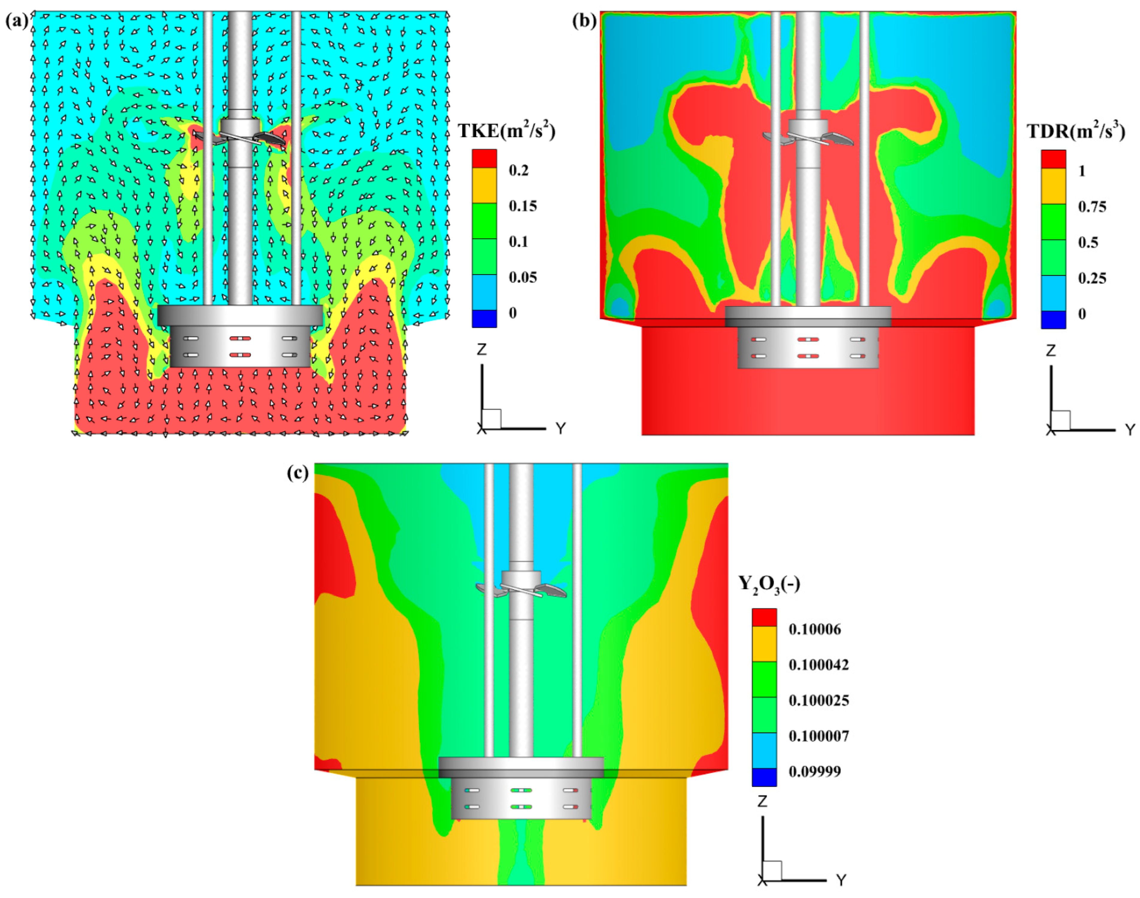
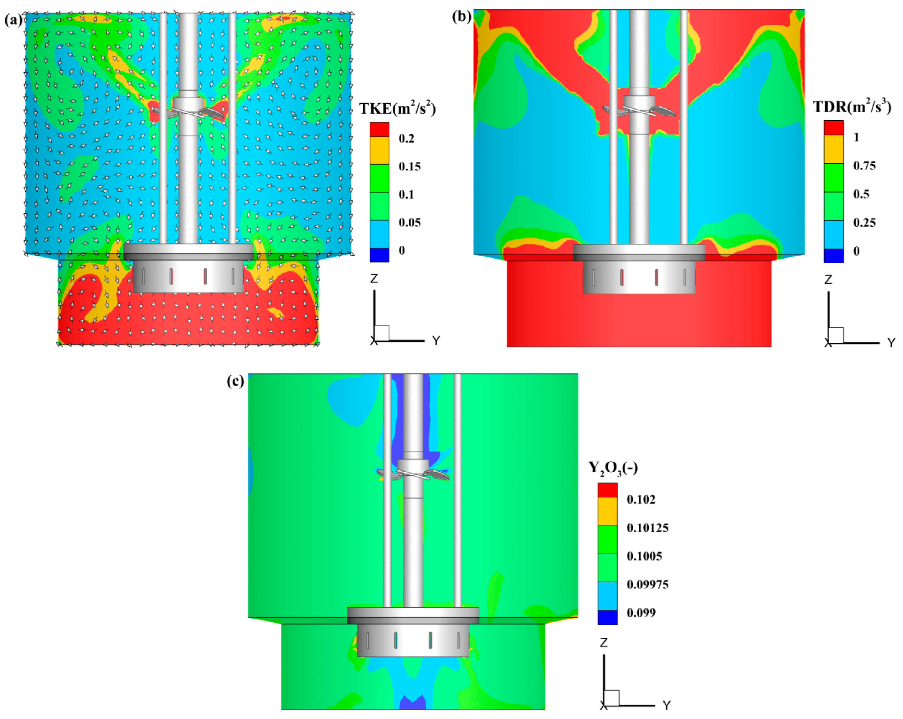
Figure 8 illustrates the effect of the horizontal hole arrangement on the distributions of TKE, TDR, and Y2O3 volume fraction. The two hole arrangement patterns are considered. The first is a vertical arrangement consisting of a single row of 10 holes. The second is a horizontal arrangement consisting of two rows, each with 10 holes, totaling 20 holes. Compared with the vertical hole arrangement (Figure 3b), the horizontal hole arrangement results in a 60% increase in peak TKE intensity. This is because the horizontal arrangement reduces the flow cross-section, leading to a marked increase in flow velocity, thereby enhancing the agitation intensity of the impeller. Moreover, the two-row configuration further amplifies this effect. When the holes are arranged horizontally, the synergy between the upper and lower impellers is notably strengthened (Figure 8a), with high TDR concentrated primarily between the two impellers and at the tank bottom. After the high-speed fluid exits through the horizontal holes of the lower impeller, it forms a circulation flow field that spans the entire tank under the axial thrust of the upper axial-flow impeller, thereby transferring the high-energy dissipation effect throughout the mixing space. Under the horizontal arrangement (Figure 8c), the Y2O3 volume fraction distribution is more uniform, with no significant gradient, and only slight local concentration differences are observed in the bottom region. This is because the radial jet induced by the horizontal holes, combined with the axial circulation generated by the upper axial-flow impeller, more effectively transports solid particles to the entire tank, resulting in a more uniform volume fraction distribution.
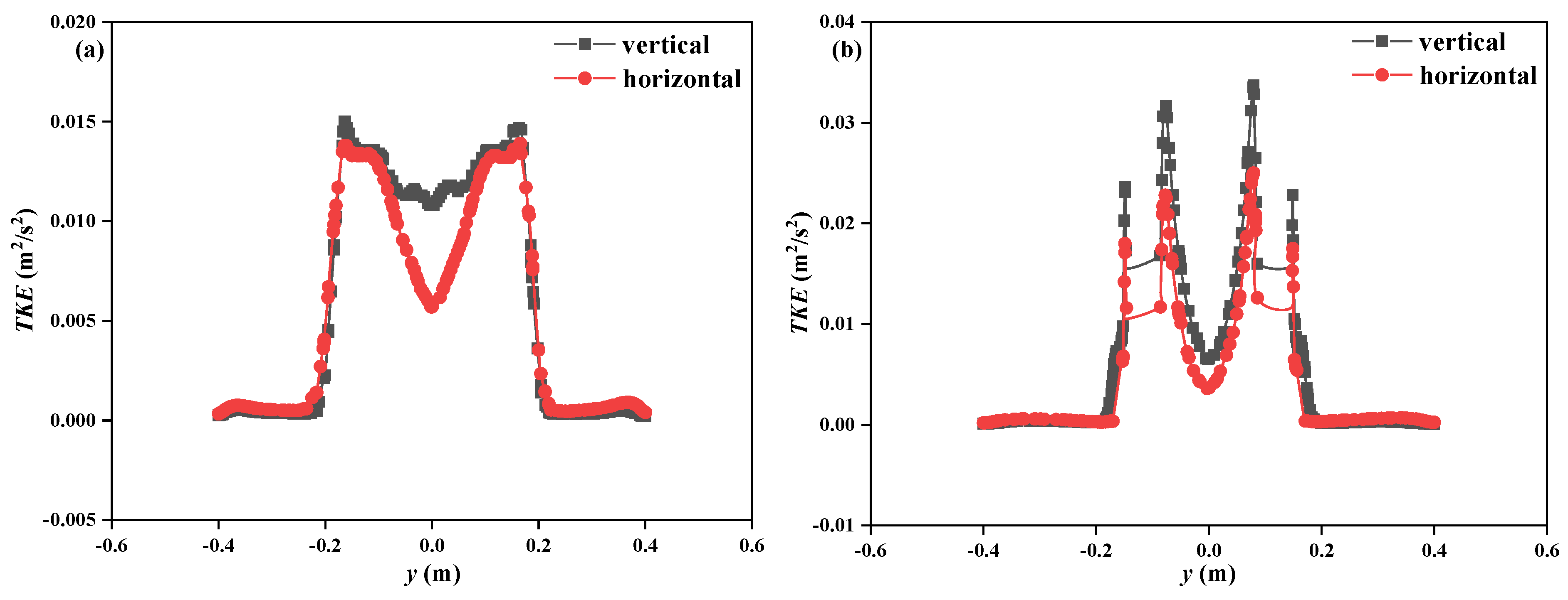
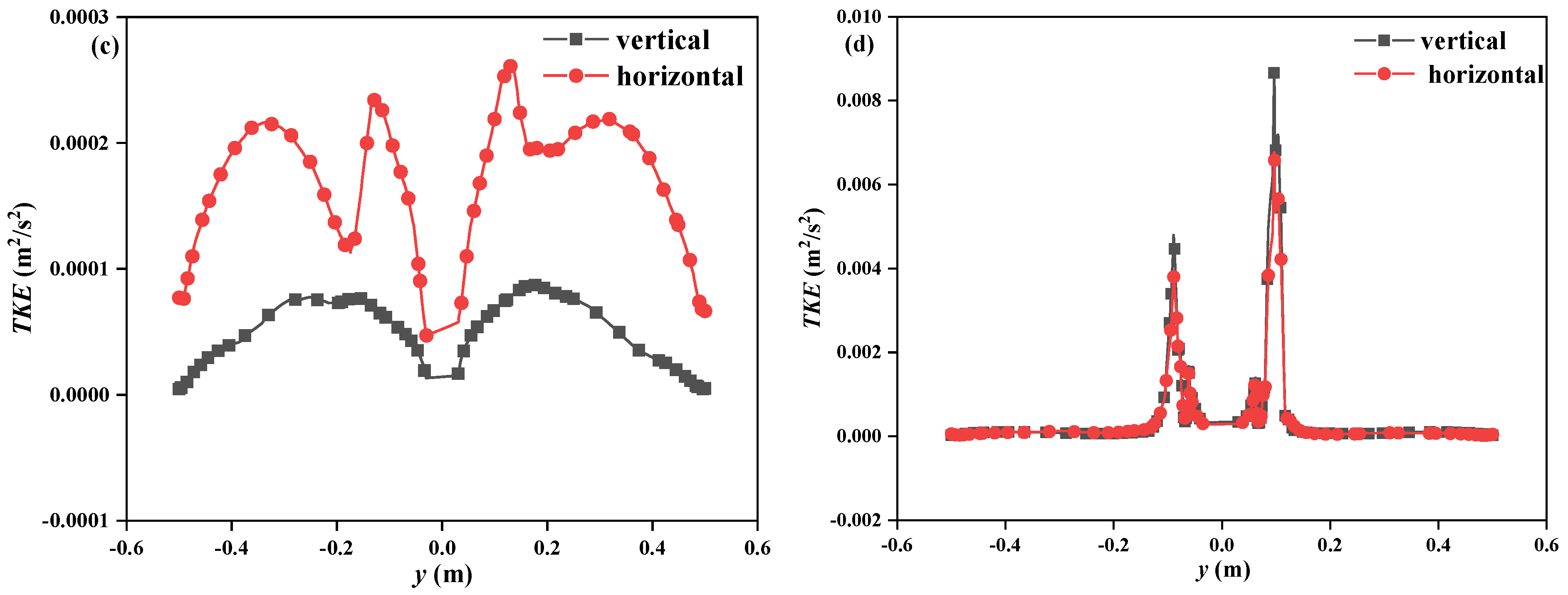
Figure 9 presents the effect of different hole arrangements on the radial distribution of TKE at various heights within the stirred tank. It can be clearly observed that in the near-bottom region at heights below 100 mm, the radial peak of TKE is significantly higher for the vertical hole arrangement than for the horizontal arrangement, indicating that the vertical holes in the lower impeller more effectively concentrate energy in the near-bottom region, thereby enhancing the bottom turbulence intensity. In contrast, at a height of 250 mm in the middle region, the opposite trend is observed, with higher TKE values corresponding to the horizontal hole arrangement. This is because the horizontal holes direct the fluid to form a radial jet, resulting in stronger local turbulence in the middle region. When the height is increased to 355 mm in the upper region, the radial distributions of TKE under the two arrangements nearly coincide. This phenomenon can be attributed to the fact that this height is far from the direct influence range of the lower impeller, where the energy input from the lower impeller has been significantly attenuated. At this height, the flow field is primarily dominated by the upper axial-flow impeller, and therefore the difference between the two hole arrangements is diminished.
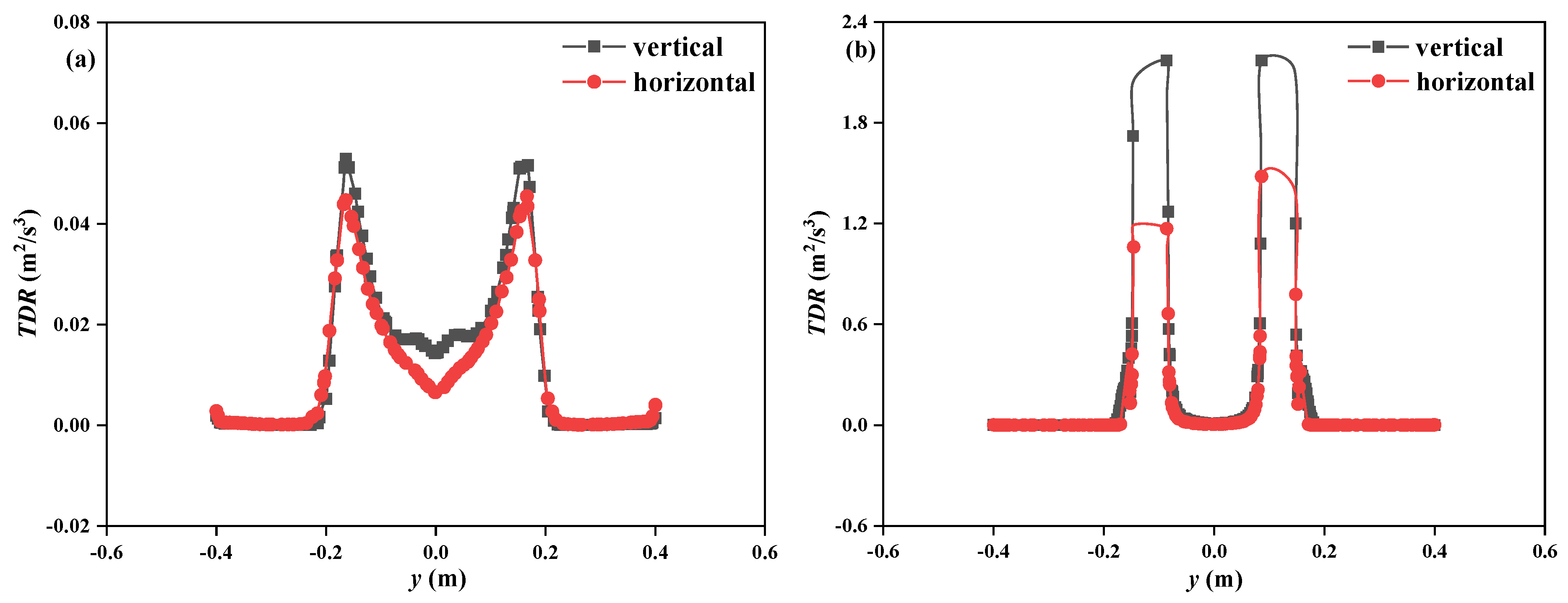
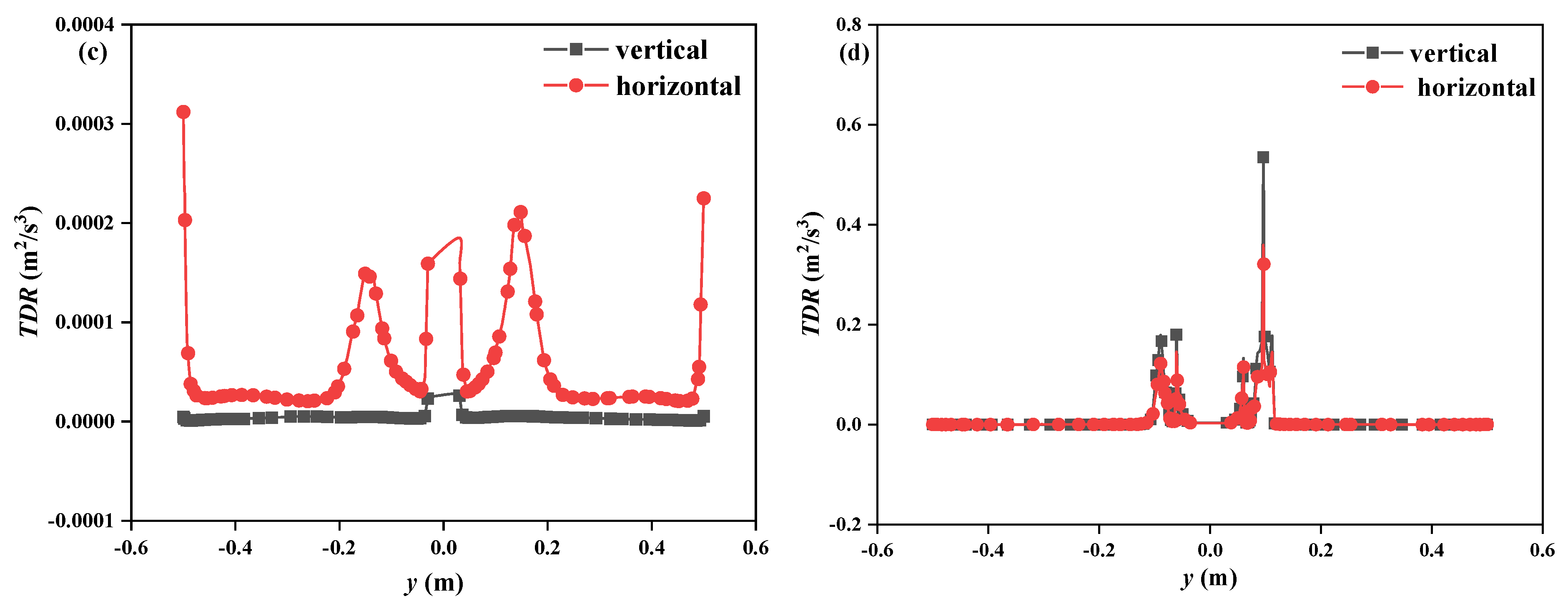
Figure 10 illustrates the effect of different hole arrangements on the radial distribution of the TDR at various heights. In the near-bottom region (h = 50 mm) and the middle-lower region (h = 100 mm), the peak TDR for the vertical hole arrangement is significantly higher than that for the horizontal arrangement. This is because the axial jet induced by the vertical holes effectively synergizes with the axial thrust of the upper axial-flow impeller, transporting high-energy fluid over a broader radial range and thereby enhancing the mixing performance in the middle-lower region. In the middle region (h = 250 mm), the TDR for the horizontal arrangement is higher, as the radial jet guided by the horizontal holes generates stronger local shear and turbulence at this height. When the height reaches the upper region (h = 355 mm), the radial distributions of TDR for the two hole arrangements almost coincide.

4.3. Effect of Total Hole Area

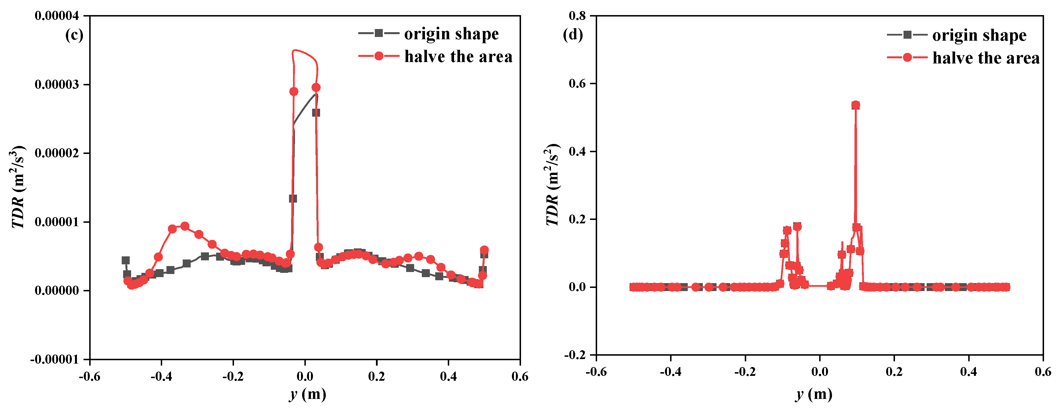
The effect of reducing the total hole area by half on the distributions of TKE, TDR, and Y2O3 volume fraction are shown Figure 11. High TKE is primarily concentrated in the bottom region near the lower impeller, as this area serves as the main energy input source. When the total hole area is reduced by half, the fluid velocity through the holes increases significantly, resulting in enhanced jet kinetic energy. This not only expands the extent and intensity of the high-TKE region at the bottom but also enables the jet to couple more effectively with the flow field generated by the upper impeller, forming a more pronounced TKE enriched zone in the middle and upper parts of the tank, thereby improving the overall energy distribution and mixing efficiency throughout the vessel. This finding indicates that appropriately reducing the hole area can effectively enhance turbulence intensity and improve mixing performance. With the total hole area halved, the fluid velocity through the holes increases markedly, leading to enhanced local shear forces. Consequently, both the extent and intensity of the high-dissipation region at the bottom are enlarged, while the TDR distribution near the upper impeller becomes more concentrated. This suggests that reducing the hole area effectively increases local turbulence intensity, thereby strengthening fluid shear and mixing. When the total hole area is reduced by half, the Y2O3 volume fraction distribution becomes more uniform, with only slight local concentration differences, indicating a marked improvement in mixing performance. This improvement can be attributed to the increased fluid velocity through the holes after the area reduction, which elevates the local turbulent kinetic energy dissipation rate and enhances the entrainment and dispersion capacity of solid particles. In addition, this effect synergizes with the axial circulation generated by the upper axial-flow impeller, enabling more effective transport of particles throughout the entire tank, thereby achieving a more uniform volume fraction distribution.
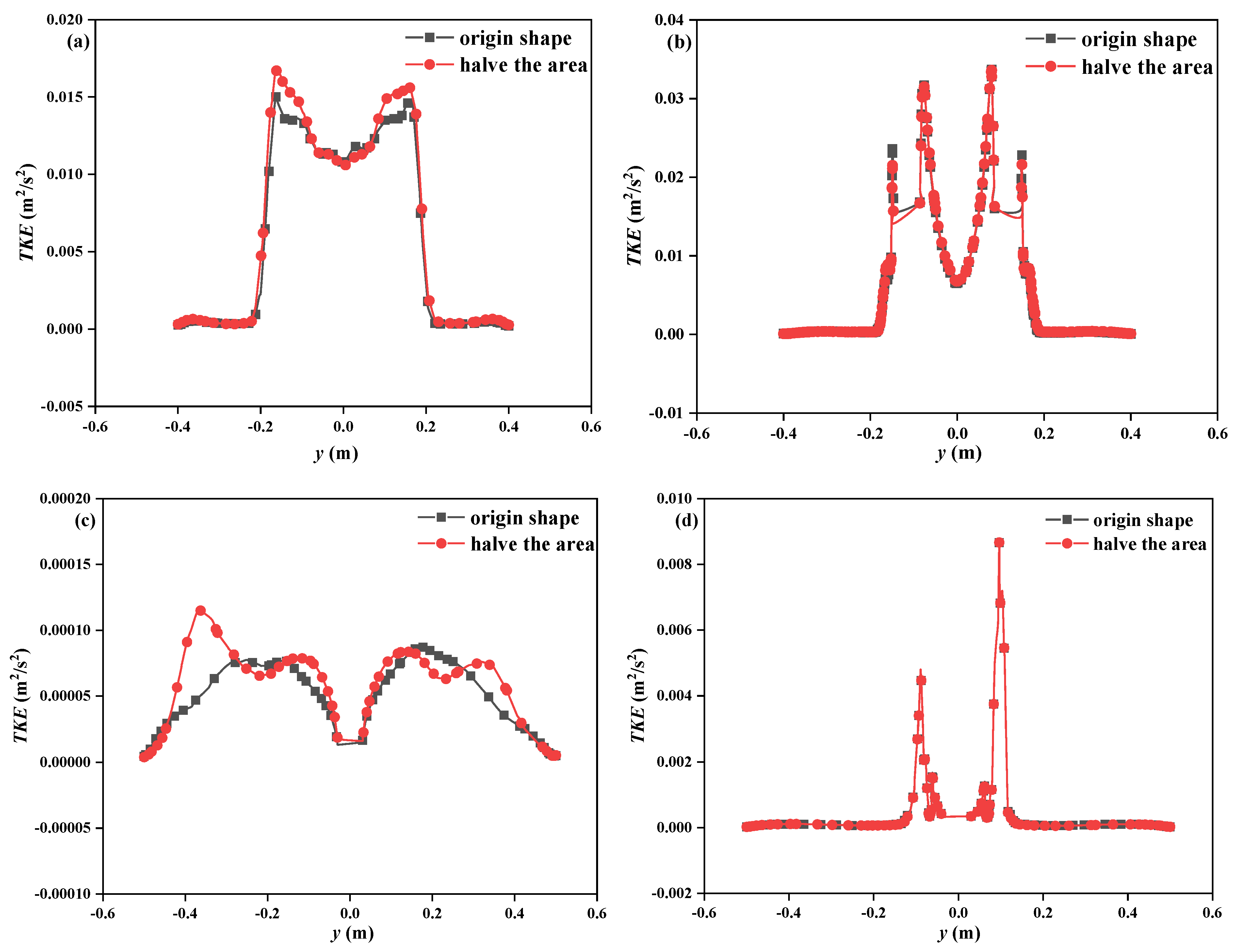
Figure 12 depicts the effect of different hole areas on the radial distribution of turbulent kinetic energy at various heights. Overall, at all four heights, the radial distribution curves of TKE for different hole areas are highly coincident, indicating that the variation in hole area has a limited effect on the radial distribution of turbulent kinetic energy. Furthermore, at h = 250 mm, the overall TKE level is relatively low due to energy dissipation. Specifically, the maximum value is only 0.0012 m2/s2, a reduction of 90% compared to 100 mm.
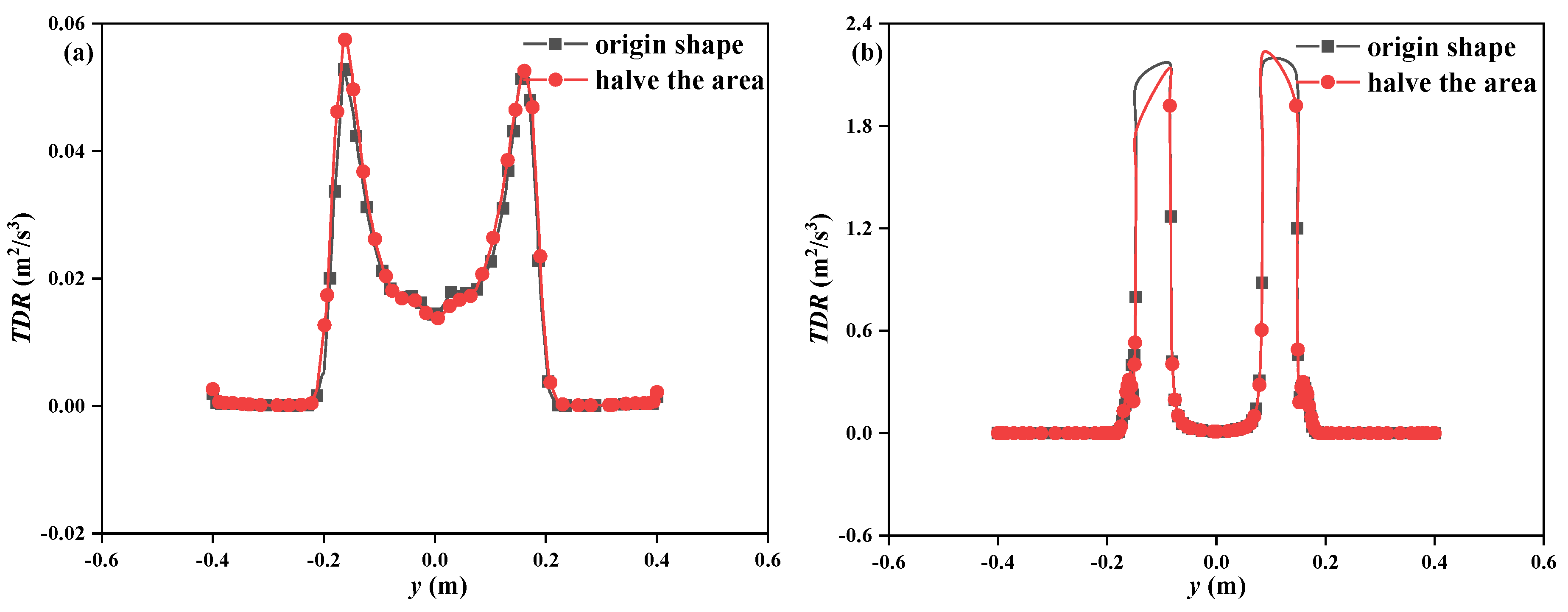
Figure 13 shows the effect of different hole areas on the radial distribution of the TDR at different heights. At the bottom of the stirred tank (h = 50 mm), the peak TDR for the reduced hole area is slightly higher than that for the original area, with the overall distribution trends being highly consistent. In the middle-lower region (h = 100 mm), the peak TDR for the reduced hole area is significantly higher and the distribution range is broader. This is because reducing the hole area increases the jet velocity of the fluid passing through the holes, enhancing local shear forces and substantially improving the turbulent kinetic energy dissipation efficiency in this region. In the middle region (h = 250 mm), the overall TDR level decreases considerably, and the difference between the two cases becomes markedly weaker, highlighting the effect of energy attenuation with height. In the upper region (h = 355 mm), the TDR curves for the two cases almost completely coincide, with a more uniform radial distribution. This is because this height is far from the direct influence of the lower impeller, and the flow field is primarily dominated by the upper axial-flow impeller, so the effect of the change in the lower hole area is counteracted by the strong axial circulation flow generated by the upper impeller.

4.4. Stirring Power

The stirring power P is calculated according to the following formula (refer to Stelmach et al.’s study) [28]
P = 2 M U D
Here, M is the torque, U is the linear velocity of the blade tip, and D is the diameter of the stirred tank.
Figure 14 illustrates the effect of different conditions on stirring power. As the stirring speed increases from 2000 r/min to 4000 r/min, the stirring power of the system also continuously rises. This is because stirring power represents the work done by the impeller on the fluid per unit time. When the rotational speed increases, the impeller drives the fluid at a higher velocity, requiring greater effort to overcome the increased fluid resistance, thus necessitating more energy input to maintain the higher motion state. When the hole arrangement is changed to a horizontal pattern, the flow cross-section increases, which reduces the obstruction to the fluid, leading to a decrease in stirring power. Reducing the hole area by half results in a slight decrease in stirring power compared with the original configuration. This indicates that reducing the hole area can achieve a certain balance between fluid mixing and energy consumption reduction.

4.5. Stirring Dead Zone

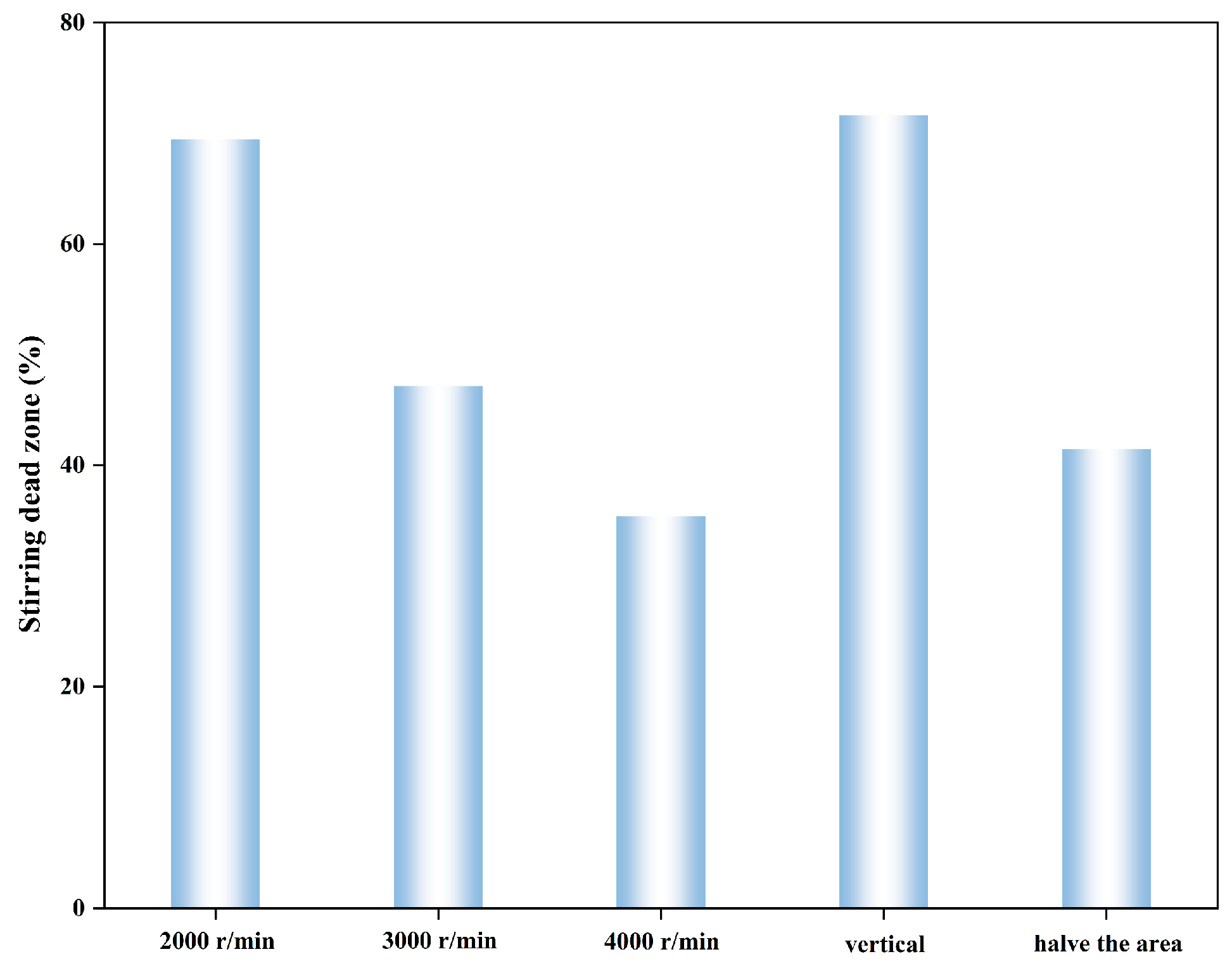
The volume of the stirring dead zone under different conditions is displayed in Figure 15. The volume of the mixing dead zone directly reflects the flow and mixing performance within the stirred tank, with a smaller value indicating better overall flow and mixing performance. Under the horizontal hole arrangement, the volume of the stirring dead zone reaches its maximum value. As the stirring speed increases, the dimensionless volume of the mixing dead zone decreases significantly, indicating that increasing the rotational speed effectively enhances the turbulence intensity and macroscopic circulation capability of the fluid in the tank, thereby reducing flow dead zones and local retention, and promoting overall flow uniformity and mixing performance. Meanwhile, appropriately reducing the opening area will enable mechanical shearing and extraction separation to continuously form a synergistic effect throughout the entire tank, optimize the spatial distribution of the flow field, and reduce the dead zone of stirring.

4.6. Y2O3 Particle Average Velocity

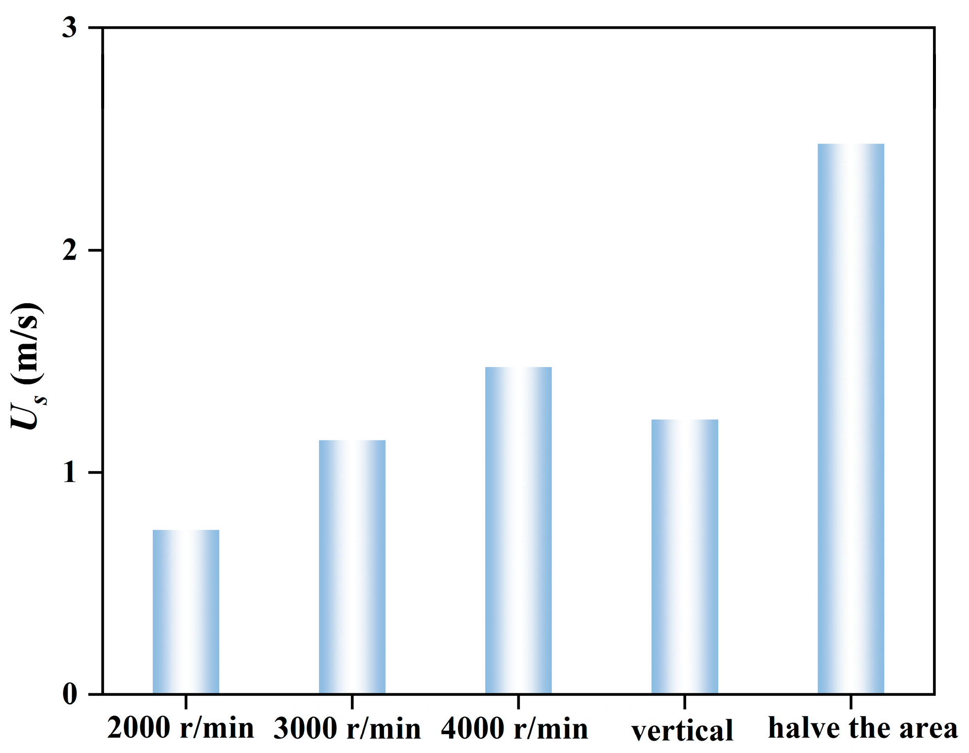
Figure 16 illustrates the effect of different conditions on the average velocity of Y2O3 particles. It can be observed that when the stirring speed increases from 2000 r/min to 4000 r/min, the average velocity of Y2O3 particles increases. This is because the higher impeller speed enhances the entrainment of the fluid on the Y2O3 particles, thereby increasing the overall average particle velocity. Under the horizontal hole arrangement, the average particle velocity is higher than that under the 3000 r/min condition but lower than that under the 4000 r/min condition, indicating that this configuration can improve particle motion intensity to some extent, yet the overall energy input to the tank remains insufficient to match the effect achieved at higher rotational speeds. When the hole area is reduced, the average particle velocity is considerably higher than that under all other conditions. This is attributed to the substantial increase in fluid jet velocity caused by the reduced hole area, which significantly enhances local shear forces and the turbulent kinetic energy dissipation rate, thereby maximizing the driving and entrainment effects on the particles.

5. Conclusions

This study focuses on a solid–liquid stirred system containing Y2O3 particles and conducts numerical simulation on particle separation characteristics enhanced by synergistic extraction and shearing. Based on the CFD method, the MRF method is employed to conduct numerical simulations of the transient flow field and particle motion behavior within a stirred tank. A systematic investigation is carried out on the effects of key operational and structural parameters, including stirring speed, hole arrangement, and hole area, on core flow and mixing performance indicators such as TKE, TDR, stirring power, volume fraction distribution of Y2O3 particles, volume of the mixing dead zone, and average velocity of Y2O3 particles. The aim is to provide theoretical support for the structural optimization and process parameter regulation of stirring equipment. The results indicate that increasing the stirring speed significantly enhances the turbulence intensity and fluid shear within the tank, effectively improving the average velocity and distribution uniformity of Y2O3 particles while substantially reducing the stirring dead zone, albeit with a simultaneous increase in stirring power. Compared with the horizontal hole arrangement, the vertical hole arrangement imposes less obstruction to the fluid, enabling more efficient energy transfer and particle outward diffusion, resulting in higher TKE and TDR throughout the tank, as well as a more uniform distribution of Y2O3 particles, thus achieving better mixing performance. Reducing the hole area increases the fluid jet velocity and local shear forces, expands the regions of high turbulent kinetic energy and turbulent kinetic energy dissipation rate at the bottom, enhances the entrainment and dispersion capacity of solid particles, and improves the mixing uniformity of Y2O3 particles. Additionally, it achieves a slight reduction in stirring power, striking a favorable balance between enhancing mixing efficiency and controlling energy consumption.
Meanwhile, the analysis method for the internal flow field of the mixing tank and the optimization ideas for structural parameters presented in this paper lay a solid theoretical and simulation foundation for further in-depth studies on particle slip velocity, drag force distribution, or a mixing uniformity index.

Author Contributions

Writing-original draft: K.W.; Validation: L.H.; Writing—review & editing: Z.W.; Investigation: F.L.; Methodology: T.J.; Visualization—Q.Z. and L.L. All authors have read and agreed to the published version of the manuscript.

Funding

This research was funded by the National Key Research and Development Program of China (No. 2024YFB3508804), Jiangxi Ganpo Talent Plan Innovative High end Talent Project (gpyc20240066). And The APC was funded by Guorui Scientific Innovation Rare Earth Functional Materials (Ganzhou) Co., Ltd.

Institutional Review Board Statement

Not applicable.

Informed Consent Statement

Not applicable.

Data Availability Statement

The data supporting the findings of this study are not publicly available due to privacy restrictions.

Conflicts of Interest

Author Kai Wu, Lixia Hu, Zhanghao Wan, Fupeng Liu and Tao Jiang were employed by the company Guorui Scientific Innovation Rare Earth Functional Materials (Ganzhou) Co., Ltd. The remaining authors declare that the research was conducted in the absence of any commercial or financial relationships that could be construed as a potential conflict of interest.

References

  1. Fradette, L.; Tanguy, P.A.; Bertrand, F.; Thibault, F.; Ritz, J.-B.; Giraud, E. CFD phenomenological model of solid–liquid mixing in stirred vessels. Comput. Chem. Eng. 2007, 31, 334. [Google Scholar] [CrossRef]
  2. Tafeh, S.; Abdel-Aziz, M.; Farag, H.; Sedahmed, G.; El-Gayar, D. Statistical modeling and optimization of heavy metal ion mass transfer in a stirred tank ion exchange system. Int. Commun. Heat Mass Transf. 2026, 175, 111038. [Google Scholar] [CrossRef]
  3. Wadnerkar, D.; Utikar, R.P.; Tade, M.O.; Pareek, V.K. CFD simulation of solid–liquid stirred tanks. Adv. Powder Technol. 2012, 23, 445. [Google Scholar] [CrossRef]
  4. Murthy, B.; Ghadge, R.; Joshi, J. CFD simulations of gas–liquid–solid stirred reactor: Prediction of critical impeller speed for solid suspension. Chem. Eng. Sci. 2007, 62, 7184. [Google Scholar] [CrossRef]
  5. Hu, X.; Ilgun, A.D.; Passalacqua, A.; Fox, R.O.; Bertola, F.; Milosevic, M.; Visscher, F. CFD simulations of stirred-tank reactors for gas-liquid and gas-liquid-solid systems using OpenFOAM®. Int. J. Chem. React. Eng. 2021, 19, 193. [Google Scholar] [CrossRef]
  6. Zhang, Y.; Qingliang, C.; Shaobo, Y.; Can, W.; Zhang, Z. Optimization of stirring parameters for millet fluid seed metering based on response surface methodology. INMATEH-Agric. Eng. 2022, 66, 373–382. [Google Scholar] [CrossRef]
  7. Dong, Z.; Ji, C.; Zhu, M.; Chen, L. Effect of Modulated Electromagnetic Stirring in Continuous Casting Bloom. Metall. Mater. Trans. B 2026, 57, 75. [Google Scholar] [CrossRef]
  8. Silva, L.O.A.; Andrade, J.F.S.; Marques, Y.E.O.; Silva, J.M.F.; Carvalho, N.B.; Almeida Torres Filho, R.; Silva, V.M. Effects of Propeller and Stirring-Speed on the Rheological, Physicochemical, and Sensory Characteristics of Creamed Honeys. J. Texture Stud. 2026, 57, e70059. [Google Scholar] [CrossRef]
  9. Kasat, G.R.; Khopkar, A.R.; Ranade, V.; Pandit, A.B. CFD simulation of liquid-phase mixing in solid–liquid stirred reactor. Chem. Eng. Sci. 2008, 63, 3877. [Google Scholar] [CrossRef]
  10. Khopkar, A.; Kasat, G.; Pandit, A.; Ranade, V. Computational fluid dynamics simulation of the solid suspension in a stirred slurry reactor. Ind. Eng. Chem. Res. 2006, 45, 4416. [Google Scholar] [CrossRef]
  11. Micale, G.; Grisafi, F.; Rizzuti, L.; Brucato, A. CFD simulation of particle suspension height in stirred vessels. Chem. Eng. Res. Des. 2004, 82, 1204. [Google Scholar] [CrossRef]
  12. Micale, G.; Montante, G.; Grisafi, F.; Brucato, A.; Godfrey, J. CFD simulation of particle distribution in stirred vessels. Chem. Eng. Res. Des. 2000, 78, 435. [Google Scholar] [CrossRef]
  13. Ochieng, A.; Lewis, A.E. CFD simulation of solids off-bottom suspension and cloud height. Hydrometallurgy 2006, 82, 1–12. [Google Scholar] [CrossRef]
  14. Montante, G.; Micale, G.; Magelli, F.; Brucato, A. Experiments and CFD predictions of solid particle distribution in a vessel agitated with four pitched blade turbines. Chem. Eng. Res. Des. 2001, 79, 1005. [Google Scholar] [CrossRef]
  15. Montante, G.; Maluta, F.; Alberini, F.; Iwasawa, S.; Takenaka, K.; Paglianti, A. Large blade impeller application for turbulent liquid–liquid and solid–liquid mixing. Can. J. Chem. Eng. 2022, 100, 2230. [Google Scholar]
  16. Xiong, X.; Liu, Z.; Tao, C.; Wang, Y.; Cheng, F.; Li, H. Reduced power consumption in stirred vessel with high solid loading by equipping punched baffles. Chin. J. Chem. Eng. 2023, 56, 203. [Google Scholar] [CrossRef]
  17. Wang, S.; Fu, S.; Zhu, C.; Hu, Y.; Wang, L.; Zhou, F. Stirring equipment optimization based on mixing characteristics of polyester reaction fluids. Chem. Eng. Process.-Process Intensif. 2025, 219, 110604. [Google Scholar] [CrossRef]
  18. Dakshinamoorthy, D.; Khopkar, A.; Louvar, J.; Ranade, V. CFD simulations to study shortstopping runaway reactions in a stirred vessel. J. Loss Prev. Process Ind. 2004, 17, 355. [Google Scholar] [CrossRef]
  19. Vilardi, G.; Verdone, N. Production of metallic iron nanoparticles in a baffled stirred tank reactor: Optimization via computational fluid dynamics simulation. Particuology 2020, 52, 83. [Google Scholar] [CrossRef]
  20. Gu, D.; Cheng, C.; Liu, Z.; Wang, Y. Numerical simulation of solid-liquid mixing characteristics in a stirred tank with fractal impellers. Adv. Powder Technol. 2019, 30, 2126. [Google Scholar] [CrossRef]
  21. Rao, D.A.; Sivashanmugam, P. Experimental and CFD simulation studies on power consumption in mixing using energy saving turbine agitator. J. Ind. Eng. Chem. 2010, 16, 157. [Google Scholar] [CrossRef]
  22. Jiang, S.; Zhao, Y.; Zhao, X.; Chen, C.; Tu, W.; Chi, Y.; Wang, J. Dense Phase Mixing in a Solid-Liquid Stirred Tank by Computational Fluid Dynamics Simulation. Processes 2025, 13, 1876. [Google Scholar] [CrossRef]
  23. Tamburini, A.; Cipollina, A.; Micale, G.; Brucato, A.; Ciofalo, M. CFD simulations of dense solid–liquid suspensions in baffled stirred tanks: Prediction of solid particle distribution. Chem. Eng. J. 2013, 223, 875–890. [Google Scholar] [CrossRef]
  24. Xie, L.; Luo, Z.H. Modeling and simulation of the influences of particle-particle interactions on dense solid–liquid suspensions in stirred vessels. Chem. Eng. Sci. 2018, 176, 439–453. [Google Scholar] [CrossRef]
  25. Guha, D.; Ramachandran, P.A.; Dudukovic, M.P.; Derksen, J.J. Evaluation of large Eddy simulation and Euler-Euler CFD models for solids flow dynamics in a stirred tank reactor. AIChE J. 2008, 54, 766–778. [Google Scholar] [CrossRef]
  26. Aubin, J.; Fletcher, D.F.; Xuereb, C. Modeling turbulent flow in stirred tanks with CFD: The influence of the modeling approach, turbulence model and numerical scheme. Exp. Therm. Fluid Sci. 2004, 28, 431–445. [Google Scholar] [CrossRef]
  27. Bin, Z.; Li, X.; Wan, Z.; Yin, Y.; Wu, Y.; Chang, H.; Tan, X. Numerical investigation of hydrodynamic performance and power consumption in stirred reactors with perforated Scaba 6SRGT impellers for non-Newtonian fluid. Can. J. Chem. Eng. 2025, 103, 2903. [Google Scholar] [CrossRef]
  28. Stelmach, J.; Kuncewicz, C.; Szufa, S.; Jirout, T.; Rieger, F. The influence of hydrodynamic changes in a system with a pitched blade turbine on mixing power. Processes 2020, 9, 68. [Google Scholar] [CrossRef]
Figure 1. Schematic diagram of the stirred tank: (a) the main body of the stirring tank (b) impeller (c) the annular cover at the bottom.
Fluids 11 00126 g001
Figure 2. Mesh independence study based on the X-axis direction.: (a) TKE (b) Y2O3.
Fluids 11 00126 g002
Figure 3. Effect of different rotational speeds on TKE: (a) 2000 r/min, (b) 3000 r/min, (c) 4000 r/min.
Fluids 11 00126 g003
Figure 4. Effect of different rotational speeds on TDR: (a) 2000 r/min, (b) 3000 r/min, (c) 4000 r/min.
Fluids 11 00126 g004
Figure 5. Effect of different rotational speeds on the volume fraction of Y2O3: (a) 2000 r/min, (b) 3000 r/min, (c) 4000 r/min.
Fluids 11 00126 g005
Figure 6. Effect of rotational speed on the radial distribution of TKE at different heights: (a) 2000 r/min, (b) 3000 r/min, (c) 4000 r/min.
Fluids 11 00126 g006
Figure 7. Effect of rotational speed on the radial distribution of TDR at different heights: (a) 2000 r/min, (b) 3000 r/min, (c) 4000 r/min.
Fluids 11 00126 g007
Figure 8. Effect of hole arrangement: (a) TKE, (b) TDR, (c) volume fraction of Y2O3.
Fluids 11 00126 g008
Figure 9. Effect of different hole arrangements on the radial distribution of TKE at different heights: (a) h = 50 mm, (b) h = 100 mm, (c) h = 250 mm, (d) h = 355 mm.
Fluids 11 00126 g009aFluids 11 00126 g009b
Figure 10. Effect of different hole arrangements on the radial distribution of TDR at different heights: (a) h = 50 mm, (b) h = 100 mm, (c) h = 250 mm, (d) h = 355 mm.
Fluids 11 00126 g010aFluids 11 00126 g010b
Figure 11. Effect of total hole area (a) TKE, (b) TDR, (c) volume fraction of Y2O3.
Fluids 11 00126 g011
Figure 12. Effect of different hole areas on the radial distribution of TKE at different heights: (a) h = 50 mm, (b) h = 100 mm, (c) h = 250 mm, (d) h = 355 mm.
Fluids 11 00126 g012
Figure 13. Effect of different hole areas on the radial distribution of TDR at different heights: (a) h = 50 mm, (b) h = 100 mm, (c) h = 250 mm, (d) h = 355 mm.
Fluids 11 00126 g013aFluids 11 00126 g013b
Figure 14. Effect of different conditions on stirring power: (a) different rotational speeds, (b) different hole arrangements and areas.
Fluids 11 00126 g014
Figure 15. Effect of different conditions on the volume of the stirring dead zone.
Fluids 11 00126 g015
Figure 16. Effect of different conditions on the average velocity of Y2O3 particles.
Fluids 11 00126 g016
Disclaimer/Publisher’s Note: The statements, opinions and data contained in all publications are solely those of the individual author(s) and contributor(s) and not of MDPI and/or the editor(s). MDPI and/or the editor(s) disclaim responsibility for any injury to people or property resulting from any ideas, methods, instructions or products referred to in the content.