Review

Active Flow Control Techniques: Classification, Analysis, and Future Trends for Automotive Applications


by
Marco Robert Herberg
1,*,
Stefano De Pinto
1,
Marco Donato de Tullio
2 and
Giuseppe Pascazio
2
1
McLaren Automotive Europe SL, 43710 Santa Oliva, Spain
2
Department of Mechanics, Mathematics and Management, Politecnico of Bari, 70125 Bari, Italy
*
Author to whom correspondence should be addressed.
Fluids 2026, 11(5), 106; https://doi.org/10.3390/fluids11050106
Submission received: 20 March 2026 / Revised: 14 April 2026 / Accepted: 21 April 2026 / Published: 23 April 2026

Abstract

Active flow control represents a key enabling technology for advancing aerodynamic performance, offering significant potential improvements in drag reduction, lift enhancement, and overall efficiency. This paper reviews state-of-the-art active flow control techniques originally developed for aerospace applications and evaluates their applicability to automotive systems, considering constraints such as packaging, efficiency, cost, and integration. A structured classification of fluidic, surface-based (including morphing), and plasma-based approaches is presented, followed by a comparative and decision-oriented assessment of their performance, technological maturity, and feasibility. The results indicate that synthetic jet actuators and morphing-based solutions provide the most balanced compromise between aerodynamic effectiveness and practical implementation. In contrast, conventional fluidic methods are limited by low system efficiency, while plasma-based techniques, although highly responsive, face challenges related to scalability and integration.

1. Introduction

In the continuous pursuit of improved vehicle performance, automotive engineers are exploring a wide range of strategies to meet increasingly demanding targets. Among these, aerodynamic optimization plays a central role, encompassing both lift (or downforce) enhancement and aerodynamic drag reduction [1,2]. For instance, given the high annual mileage of long-haul trucks (approximately 160,000 km/year), even modest reductions in aerodynamic drag can lead to significant savings in fuel consumption and operating costs [3]. In high-performance vehicles, high cornering speeds require high-lift aerodynamic configurations capable of generating the necessary downforce to maximize tire grip. However, high-lift surfaces inherently lead to increased induced drag, which compromises straight-line performance. Consequently, an optimal balance between downforce generation and drag minimization must be achieved [4]. Different methods to generate downforce such as inverted wings, diffusers, and vortex generators have been studied, with complex geometry involving aerodynamic interaction between the various body components [5]. Moreover, and particularly in the case of high-speed road cars, the aerodynamics should be properly taken into account so as to achieve safety, which is a primary factor [6].
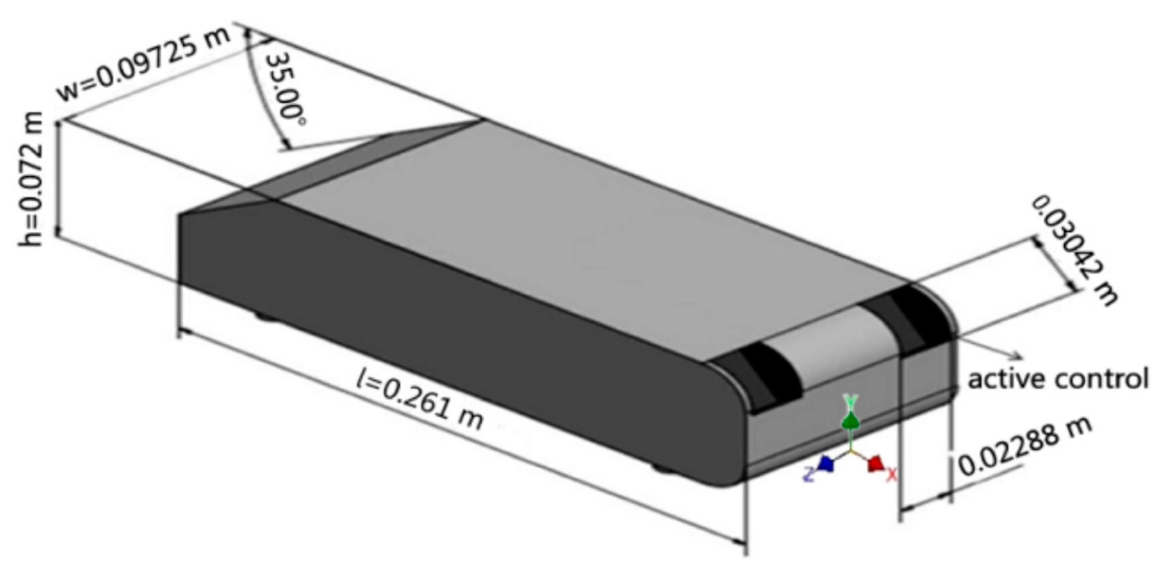
Various strategies have been developed to reduce aerodynamic drag, all based on altering the flow field around the vehicle; these approaches generally fall into two main categories: passive and active flow control methods. Passive methods rely exclusively on geometric modifications of the vehicle body, such as tailored surface profiles, external aerodynamic appendages, or flow-guiding devices, to manipulate airflow. These solutions do not require any additional energy input during operation and are inherently robust. However, each passive configuration is optimized for a specific operating condition and cannot adapt to changing flow regimes. As a result, passive solutions may lead to degraded performance or even flow instabilities when operating outside their optimal range [7,8]. Active flow control (AFC) techniques overcome these limitations by enabling real-time manipulation of the flow field based on operating conditions; unlike passive solutions, AFC systems can be activated or deactivated on demand, allowing the aerodynamic response of the vehicle to adapt dynamically [9]. These strategies are primarily applied to modify boundary layer behavior, delay separation, alter wake structures, or control vortex formation. However, this adaptability comes at the cost of additional system complexity and increased energy consumption [10]. In automotive aerodynamics, the evaluation of flow behavior is often carried out using simplified geometries that capture the essential physics of vehicle wakes while remaining computationally and experimentally manageable. One of the most widely adopted models is the Ahmed body, introduced by Ahmed et al. [11] through an extensive experimental campaign aimed at understanding flow structures around bluff bodies. Their work demonstrated that the rear slant angle is the dominant parameter affecting wake topology and aerodynamic drag. Further experimental studies by Brunn et al. [12] illustrated the major wake flow regimes as a function of the rear slant angle. Results showed that the drag coefficient reaches a maximum at a slant angle of approximately 30°. For larger angles, the longitudinal vortices break down, and the wake becomes dominated by spanwise structures, leading to a reduction in pressure drag. Over the past decade, a growing number of review papers have investigated active and passive flow control techniques aimed at improving aerodynamic performance. While these studies provide valuable overviews, they often remain descriptive and primarily focus on cataloging available actuation concepts rather than critically assessing their applicability under realistic operating conditions. Jahanmiri [13] provided an early classification of major AFC techniques based on their actuation mechanisms, including a distinction between feedforward (open) and feedback (closed) control strategies. Although comprehensive at the time, this review is mainly oriented toward aerospace applications and does not account for several technological developments that have emerged in recent years, such as plasma-based actuators and hybrid control strategies. Maine et al. [14] reviewed experimental and numerical studies published between 2010 and 2018, focusing on drag reduction levels exceeding 3%. Their findings are consistent with those reported by Mukuk et al. [15], indicating maximum drag reductions of approximately 20%; however, numerical investigations suggest that Coandă-based flow control applied to the rear of bluff bodies could further enhance performance, potentially enabling drag reductions of up to 50%. The Ahmed body remains the canonical benchmark for studying wake dynamics and aerodynamic drag in ground vehicles due to its simplified geometry, which enables controlled and reproducible investigations of flow separation and vortex structures; however, its lack of realism, particularly the absence of rotating wheels, detailed underbody geometry, and complex front-end features, limits its applicability to real vehicles. To address these limitations, more advanced generic models such as the DrivAer configuration have been introduced [16,17,18]. Initially developed through a collaboration between the Technical University of Munich (TUM) and BMW, the DrivAer model represents a realistic vehicle geometry while remaining suitable for both experimental and numerical investigations.
Unlike the Ahmed body, it comprises a family of configurations (fastback, notchback, and estate) and can incorporate additional features such as rotating wheels and detailed underbody geometries, enabling a more accurate representation of real aerodynamic conditions. Although these models capture complex flow interactions more effectively, the Ahmed body remains the dominant reference in drag reduction and AFC studies due to its simplicity, comparability, and widespread use in the literature; consequently, while the present review primarily focuses on Ahmed-based studies, the inclusion of DrivAer demonstrates the ongoing transition toward more realistic aerodynamic analyses.
Cho et al. [19] investigated the aerodynamic performance of various drag reduction devices applied to the DrivAer model, providing one of the first systematic comparisons on a realistic passenger-car geometry. Their study showed that passive devices such as rear spoilers and horizontal and vertical planes located on C-pillar or on the rear trunk can achieve drag reductions on the order of 3–5.1%, depending on the configuration and flow conditions; the results also demonstrated how these devices interact with complex flow features, including rotating wheels and underbody structures, which significantly influence overall effectiveness. Ashton et al. [20,21,22] conducted comprehensive experimental and numerical investigations of the DrivAer model, reporting drag coefficient values typically in the range of Cd ≈ 0.25–0.30, depending on the configuration.
Their work emphasized the increased flow complexity compared to simplified models, including strong wheel–wake interactions and three-dimensional separation structures, making the DrivAer model particularly suitable for evaluating advanced flow control techniques under realistic conditions. Wang et al. [23] analyzed the aerodynamic behavior of the DrivAer model, Estate variant, under moving-ground conditions, demonstrating that the inclusion of a moving ground and rotating wheels can alter drag values by approximately 5–15% compared to fixed-ground simulations with a Cd ≈ 0.28, in line with Ashton et al.’s [20] results range. Their results showed significant modifications in wake structure and underbody flow, affecting both separation regions and pressure distribution. These findings demonstrate the importance of realistic boundary conditions when assessing flow control strategies. Therefore, while the Ahmed body remains a valuable benchmark for fundamental investigations and is widely used in this review, more realistic models such as DrivAer are essential for accurately assessing the effectiveness of AFC techniques under real operating conditions. However, this review does not include a detailed assessment of vehicle dynamics integration; instead, it focuses on the aerodynamic performance and feasibility of each method; here, “performance” refers to the achievable drag reduction and/or downforce generation, while “aerodynamic feasibility” denotes the practical applicability of the method in real-world conditions, including aspects such as implementation complexity, scalability, and compatibility with production vehicles.
The points of novelty of the present review are summarized as follows:
  • To provide an updated assessment of the most relevant active flow control techniques originally developed for aerospace applications and evaluate their potential deployment in the automotive sector.
  • To introduce a comparative methodology integrating aerodynamic performance with system-level constraints, including packaging feasibility, operational complexity, cost, and weight.
The paper is organized into thematic sections addressing different actuation strategies and analyzing their influence on aerodynamic coefficients. Section 2 explores the various methodologies employed for boundary-layer control. Section 3 evaluates the constraints affecting the feasibility of each method, including technological, energetic, and implementation-related aspects. Finally, Section 4 summarizes the main findings and provides considerations on which techniques have potential for future real-world applications. Three main AFC families are examined, with particular emphasis on performance, limitations, and practical applicability.

2. Flow Control Through Active Methods

The active flow control methods discussed in this review are categorized as follows:
  • Fluidic techniques, involving jet injection and/or suction.
  • Surface-based techniques, based on mechanical modification of geometry.
  • Plasma actuators, which alter the boundary layer through ionization and electrical forcing.
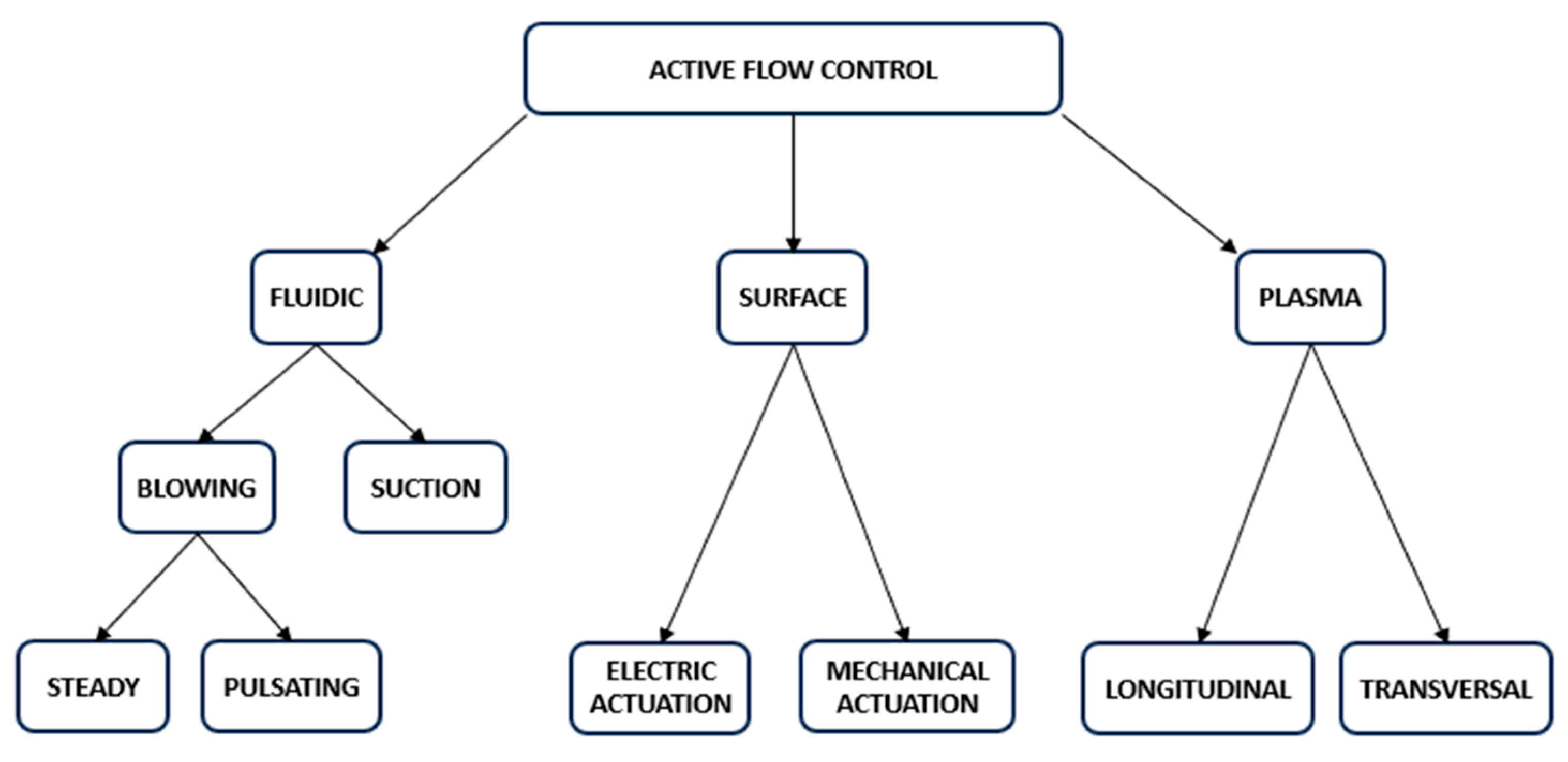
Figure 1 provides a visual overview of the different variants of active flow control (AFC). The primary aerodynamic objectives of these techniques include drag reduction and downforce enhancement, both of which are critical to improving overall vehicle performance. Drag reduction aims to decrease aerodynamic resistance, thereby improving straight-line speed, fuel efficiency, and overall energy consumption. In contrast, downforce enhancement improves vehicle stability, handling, and tire grip, particularly at high speeds and during cornering. Achieving an optimal balance between these objectives is essential, as excessive downforce generation may lead to increased aerodynamic drag, negatively impacting performance under certain operating conditions. Therefore, a detailed aerodynamic design employing an adaptive aerodynamic concept is required, allowing an optimal compromise to be achieved between fuel consumption and performance, e.g., [24].
While the previous sections classify active flow control (AFC) techniques according to their actuation mechanisms, their practical applicability strongly depends on the specific automotive context. In particular, different application domains, ranging from simplified benchmark models to passenger vehicles, high-performance cars, and heavy-duty transport, are characterized by distinct aerodynamic objectives, flow features, and design constraints. As a result, the effectiveness and feasibility of each AFC approach cannot be assessed independently of its intended application. In simplified configurations, AFC techniques are primarily used to investigate fundamental flow mechanisms under controlled conditions. In contrast, real vehicle applications introduce additional constraints such as packaging, system efficiency, and robustness, which significantly affect the achievable performance. Moreover, the aerodynamic objectives may vary across applications: drag reduction is typically dominant in passenger and heavy-duty vehicles, whereas high-performance applications often prioritize aerodynamic balance and downforce generation.
For this reason, the discussion presented in the following section is interpreted with reference to these different application domains, highlighting how the suitability of each AFC technique varies depending on the specific use case.

2.1. Fluidic Methods

Fluidic techniques rely on the injection or removal of air from the main flow field in either steady or unsteady conditions, with jets oriented tangentially or orthogonally to the surface [25,26].
The effectiveness of these strategies is evaluated using specific performance metrics.
Danò et al. [27] proposed the jet momentum coefficient Cμ, defined as
C µ = m ˙ V j 1 / 2 ρ ∞ V ∞ 2 A r e f
where m ˙ is the mass flow rate, ρ ∞ is free-stream density, V ∞ is free-stream velocity, and A r e f is the reference area; the jet velocity (Vj) reported in the study refers to averaged value at the injection slot. Brunet et al. [28] share the same coefficient as per Danò [27] for steady blowing but propose for pulsed blowing (squared signal) the following jet momentum coefficient Cμ
C µ = 1 D C < q m > t   ∗ < V j > t 1 / 2 ρ ∞ V ∞ 2 A r e f
where < q m > t is the time-averaged mass flow rate, < V > t is the time-averaged output velocity, DC is the duty cycle, and the rest of the parameters are as above.
In the context of active flow control, the introduction of the duty cycle (DC) enables temporal modulation of the actuation, making it intermittent rather than continuous; this parameter, defined as the fraction of time during which the actuator is active within a given cycle, allows for precise control of the energy input into the flow.
However, although formulations explicitly accounting for the duty cycle have been proposed [28], in many studies, the jet velocity is still expressed as a time-averaged quantity, consistent with the definition adopted in Equation (1), as discussed later.
Rouméas et al. [29] further introduced a power efficiency metric η , proposed originally for steady suction only, but with a small adaptation that can be defined as well for steady blowing as
η = P e c P c ;   P e c = Δ F x V 0   a n d   P c = 1 / 2   k ρ   V j 3 S j
where P e c represents the power saved through the aerodynamic improvements and P c is the actuation power, k represents a coefficient accounting for total pressure losses in the actuation system, Sj is the suction/blowing area, Vj is the speed in that area and ΔFx is the drag reduction induced by the fluidic method. The actuation power is estimated from the time-averaged kinetic energy flux of the jet, representing the fluid mechanical power input, while additional system-level losses (e.g., compression and electrical inefficiencies) are not accounted for. Density requires clarification depending on the actuation method; for steady suction, the freestream air density is considered, as the control power is estimated from the kinetic energy flux of the entrained ambient fluid. For steady blowing, assuming the jet is low in velocity and near-ambient temperature, the freestream density represents a reasonable approximation. However, for high-speed or thermally altered jets, the density at the jet exit should be used to accurately evaluate both the kinetic energy flux and the mass flow rate. In the present review, the freestream density is assumed unless otherwise specified. For pulsed blowing, in line with Brunet et al. [28], the actuation power is evaluated as the time-averaged kinetic energy flux of the jet. Assuming a duty cycle D C , this leads to P c = D C ⋅ 1 2 ρ A j V o n 3 , highlighting the potential for reduced power consumption compared to steady blowing.
The control is considered efficient when the value η is equal to or greater than 1.
Fluidic methods are subdivided into:
  • Steady suction and blowing;
  • Pulsed blowing;
  • Synthetic jets;
  • Co-Flow Jets (CFJ).

2.1.1. Steady Suction and Blowing

Suction has long been used in aerospace to stabilize boundary layers, delay transition, and suppress separation. Rouméas et al. [29] demonstrated a 17% drag reduction on an Ahmed body using a suction slot located at the rear slant, resulting from the elimination of the separated flow region on the rear slant when suction was active.
Harinaldi et al. [30] explored a reversed Ahmed body to simulate a family van, using suction on the rear; numerical and experimental data align well, showing a drag reduction of approximately 16%, which is close to the results of Rouméas et al.’s [29] study (Figure 2). Tarakka et al. [31] conducted a similar setup but, instead of using slots, employed cylindrical holes, achieving a lower drag reduction of about 11% compared to Harinaldi et al.’s [30] setup.
Blowing techniques, either steady or unsteady, are commonly classified according to jet orientation relative to the surface as tangential, normal (orthogonal), or inclined, each influencing the flow through distinct mechanisms and levels of control authority. Although many active flow control (AFC) strategies in automotive aerodynamics have been developed for specific vehicle geometries, their effectiveness relies on physical mechanisms originally identified in canonical boundary layer studies, primarily within an aeronautical context. In this framework, the work of Gilles Godard et al. [32,33,34] provides a comprehensive investigation of flow separation control using both passive and active vortex generators, including slotted and round jets. Their results show that streamwise vortices enhance near-wall momentum transfer, reducing boundary layer thickness and shape factor (by up to ~20–25%) and delaying separation. Although developed for aeronautical applications, these mechanisms are directly relevant to bluff-body aerodynamics, where similar separation occurs at the rear of ground vehicles. Consistently, Radespiel et al. [35] reviewed steady blowing for high-lift configurations, demonstrating how momentum injection via tangential and inclined jets effectively delays separation. Their work further demonstrates boundary layer energization and vortex generation as the key mechanisms underlying active flow control and reinforces their applicability to bluff-body flows, where separation control and momentum transfer are central to wake manipulation and drag reduction. High-lift configurations based on steady blowing and Coandă flaps can achieve maximum lift coefficients up to C L ≈ 5 , which can be further increased to C L ≈ 6 – 7 through leading-edge optimization and suction. In extreme conditions, values approaching C L ≈ 8 have been reported.
Among these approaches, tangential blowing, where the jet is aligned with the surface, is primarily used to energize the near-wall flow and counteract viscous losses. It is important to distinguish between classical boundary layer control (BLC) obtained through tangential or inclined blowing and the Coandă effect, as these mechanisms rely on different physical principles. In BLC, the injected momentum is primarily used to compensate viscous losses within the boundary layer, thereby delaying or preventing flow separation, and this mechanism can be applied to both flat and curved surfaces. In contrast, the Coandă effect occurs when a high-momentum jet is tangentially injected over a curved surface, causing the jet to remain attached to the surface due to entrainment and centrifugal effects, generating a low-pressure region and a significant deflection of the external flow. Although high-momentum blowing over curved geometries may involve both mechanisms, the distinction remains important when interpreting aerodynamic performance and actuator efficiency. This blowing technique has been widely applied both to airfoils, through slot injection at the leading or trailing edge, and to automotive configurations such as the Ahmed body. For example, Mestiri et al. [36] investigated steady tangential blowing on an Ahmed body, reporting drag reductions between 6% and 10.4% depending on the Reynolds number. Their flow visualizations indicate that tangential blowing enlarges the separated region over the rear window, thereby disrupting the formation of counter-rotating longitudinal vortices along its lateral edges. On the other hand, orthogonal blowing, where the jet is injected perpendicular to the surface, primarily enhances mixing and disrupts coherent wake structures; this configuration is commonly used in bluff body wake control and in automotive applications through microjets or jet arrays positioned at the rear of the vehicle. Aubrun et al. [37] demonstrated that orthogonal microjet injection on a 25° Ahmed body slant can reduce drag by approximately 9–14% while also significantly modifying lift characteristics due to strong wake interaction.
Inclined blowing represents an intermediate configuration that combines the advantages of both tangential and orthogonal injection, simultaneously energizing the boundary layer and promoting mixing in the outer flow. In automotive aerodynamics, inclined jets are frequently applied on the rear slant of the Ahmed body on diffusers and spoilers to optimize flow attachment and wake development. Similarly, Littlewood et al. [38] demonstrated that steady blowing on a simplified square-back vehicle can achieve drag reductions of up to approximately 8–10%, depending on the blowing momentum coefficient and the jet orientation. McNally et al. [39] showed that combining tangential and orthogonal blowing on a modified Ahmed body can yield drag reductions of approximately 2–3%, while more aggressive configurations, such as the distributed actuators proposed by Zhang et al. [40], have demonstrated drag reductions up to 29%, albeit with relatively low overall efficiency (0.36) according to Equation (3) due to a large energy consumption to obtain the maximum drag reduction. Furthermore, CFD studies by Wassen et al. [41,42] demonstrated that combined blowing and suction strategies applied on the rear slant can achieve drag reductions of approximately 9.4%, emphasizing the importance of jet orientation and system integration. A drag reduction of 9.4% corresponds to an equivalent decrease in propulsion power. However, as the control strategy is active, additional energy input is required. The propulsion power to overcome the aerodynamic drag for natural flow is defined by
P D = F D U 0 = 1 2   C d ρ B H U 0 3
and the blowing fluid power proposed as
P a c t = 1 2   m ˙ s l i t v s l i t 2
where “B” is the vehicle’s width, “H” is the vehicle’s height, “U0” is the average tunnel air velocity, “ ρ ” is the tunnel density, “ m ˙ s l i t ” actuation’s mass flow rate and “vslit” is the actuation speed.
A simplified estimation shows that the actuation power amounts to only 0.6% of the baseline propulsion power ( P a c t / P D = 0.006 ), resulting in a net energy saving of approximately 8.8%; it should be noted that this estimate does not account for potential losses in practical implementations. Overall, these studies demonstrate that jet orientation plays a critical role in determining the balance between boundary layer energization and wake manipulation, with tangential blowing being more efficient for separation delay, orthogonal blowing more effective for wake disruption, and inclined blowing offering a balanced and often optimal solution between the two mechanisms. Blowing can be effectively used on aerodynamic devices such as wings to enhance downforce (ΔCL = 0.105) with only a minor drag penalty (ΔCD = 0.01) [43]. When implemented through a Coandă-based flow control system, the injected jet remains attached to the curved surface, energizing the boundary layer and suppressing trailing-edge separation. This results in a more favorable pressure distribution along the airfoil, effectively increasing its aerodynamic camber and lift capability. Unlike conventional lift augmentation, the drag increase remains limited because the flow stays attached and the wake structure is improved, making Coandă blowing a highly efficient active flow control strategy. Building on the previously discussed steady blowing strategies, pneumatic active flow control has been extensively investigated for heavy vehicles, showing significant aerodynamic benefits. Early studies on pneumatic configurations demonstrated that tangential blowing applied at the trailer curved edges can achieve drag reductions of up to 31%, mainly through enhanced entrainment and increased base pressure, which suppress large-scale separation and even allow additional functionalities such as aerodynamic braking and crosswind stabilization [44]. More recent investigations on European-type truck models confirm these mechanisms, demonstrating that blowing to curved rear geometries effectively keeps the flow attached by generating a low-pressure region that attracts external flow toward the surface (Coandă effect). This results in a clear reduction in the wake recirculation zone, as evidenced by PIV measurements, and leads to drag reductions up to about 12.6% compared to the baseline configuration [45]. Overall, these studies demonstrate that steady Coandă-based blowing modifies the wake topology by reducing separation and recirculation, thereby improving aerodynamic efficiency, with performance strongly dependent on actuator placement, jet momentum, and interaction with underbody flow structures.

2.1.2. Pulsed Blowing

Steady blowing has been shown to improve aerodynamic performance of both slender bodies such as airfoil profiles and bluff bodies such as simplified vehicle models by altering wake characteristics and reducing separation; however, excessive steady blowing can unfavorably alter the boundary layer thickness and wake dynamics, potentially increasing total drag under certain conditions [46]. In this context, unsteady actuation techniques such as pulsed blowing have emerged as a more efficient alternative, particularly in aerospace applications where flow control authority must be achieved with minimal energy input. In high-lift configurations, experimental studies conducted by Brunet et al. [28] have demonstrated that pulsed blowing can significantly delay flow separation and increase lift, extending the operational angle-of-attack range before stalling. These improvements are especially relevant for modern aircraft, where enhanced lift-to-drag ratios directly translate into better fuel efficiency and reduced emissions. The underlying physical mechanisms were established by Greenblatt et al. [47], who demonstrated that periodic excitation interacts with the natural instabilities of the shear layer, promoting the formation and organization of large-scale coherent vortical structures; these structures play a dominant role in momentum transfer and entrainment, enhancing the exchange of high-momentum fluid toward the wall and thereby re-energizing the boundary layer.
In the context of pulsed blowing, this mechanism is achieved through the periodic injection of momentum via intermittent jets, which effectively trigger and control these instabilities; as a result, boundary layer separation can be delayed or even suppressed with momentum input levels one to two orders of magnitude lower than those required for steady blowing, making the technique highly attractive for practical implementation. The effectiveness of pulsed blowing has also been validated in flight-relevant conditions. Whalen et al. [48] conducted both wind tunnel and full-scale flight tests on a vertical tail equipped with active flow control actuators based on pulsed blowing. The system, installed near the leading edge of the vertical stabilizer, was shown to significantly enhance side-force generation at high sideslip angles, where baseline configurations typically experience massive flow separation. Quantitatively, the results indicated increases in effective side-force of up to a maximum of 14%, along with a marked improvement in yaw control authority. Additionally, the technology enabled similar control performance at reduced rudder deflection angles, showing the potential for smaller tail sizing, reduced structural loads, and overall drag reduction in off-design flight conditions. Building upon these aerospace developments, the application of pulsed blowing has been extensively extended to bluff-body flows, particularly in the automotive sector. Closed-loop flow control of bluff bodies has been extensively investigated in the literature, particularly in the context of wake stabilization and drag reduction [49,50,51], where reductions in drag on the order of 10–20% and a significant attenuation of wake fluctuations have been reported, depending on the actuation strategy and flow conditions. A central contribution of Pfeiffer’s work [52] lies in the identification of LPV models for the actuated flow and the transient crosswind gust response, capturing the dependence of the aerodynamic dynamics on parameters such as free-stream velocity and crosswind angle. The approach relies on feedback-controlled Coanda actuation at the trailing edges, combined with multivariable control strategies based on both robust H∞ and linear parameter-varying (LPV) frameworks. These models enable the synthesis of gain-scheduled controllers with improved performance compared to conventional robust designs. Wind tunnel experiments on 2D and 3D bluff bodies demonstrate significant drag reduction (up to 35% for the 2D case and about 15% for the 3D configuration) and effective attenuation of unsteady aerodynamic loads, particularly in terms of yaw moment and side-force fluctuations, leading to enhanced lateral stability under realistic gust conditions. Unsteady flow control using pulsed jets has also been widely investigated on the Ahmed body, a canonical model for ground vehicle aerodynamics. Joseph et al. [53,54] reported drag reductions of up to approximately 8% for the 25° slant configuration using both pulsed jets and MEMS-based micro-jets. Optimal performance was achieved when the actuation frequency matched the natural shear-layer instabilities, leading to enhanced mixing, reduced recirculation, and increased base pressure. Further improvements have been demonstrated by He et al. [55], who achieved drag reductions of up to approximately 9.2% on a notchback Ahmed body through the combined use of pulsed jets and a genetically inspired optimization strategy. Their results demonstrate the importance of tuning actuation parameters to effectively control the three-dimensional wake, promoting partial flow reattachment and suppressing large-scale separation. This results in a more compact and stabilized wake, reduced recirculation, and a significant increase in base pressure, ultimately improving aerodynamic efficiency. Even larger drag reductions have been reported by Bideaux et al. [56], who applied pulsating flow control to an Ahmed body and observed reductions of up to 20% at an actuation frequency of 500 Hz compared to uncontrolled conditions. In their study, a solenoid valve was used to modulate the airflow issuing from the rear slant, demonstrating the strong sensitivity of the control effectiveness to actuation frequency. Gillièron [57] subsequently confirmed the repeatability of these results and provided additional insight into the wake topology, showing how pulsed actuation modifies the large-scale flow structures behind the bluff body. Overall, these studies confirm that pulsed blowing represents a highly effective and versatile active flow control strategy. Compared to steady blowing, periodic actuation enables a significant reduction in the required mass flow rate for a given control authority, thereby improving overall efficiency. The effectiveness of the technique is strongly linked to the actuation frequency, with optimal performance typically achieved when the forcing is tuned to the natural instabilities of the shear layer. This highlights a fundamental advantage of unsteady forcing: rather than relying solely on continuous momentum injection, pulsed blowing exploits intrinsic flow instabilities to enhance mixing, accelerate momentum transfer, and promote flow reattachment. These characteristics make it particularly attractive for real-world applications, where efficiency, robustness, and reduced energy consumption are critical design constraints.

2.1.3. Synthetic Jets

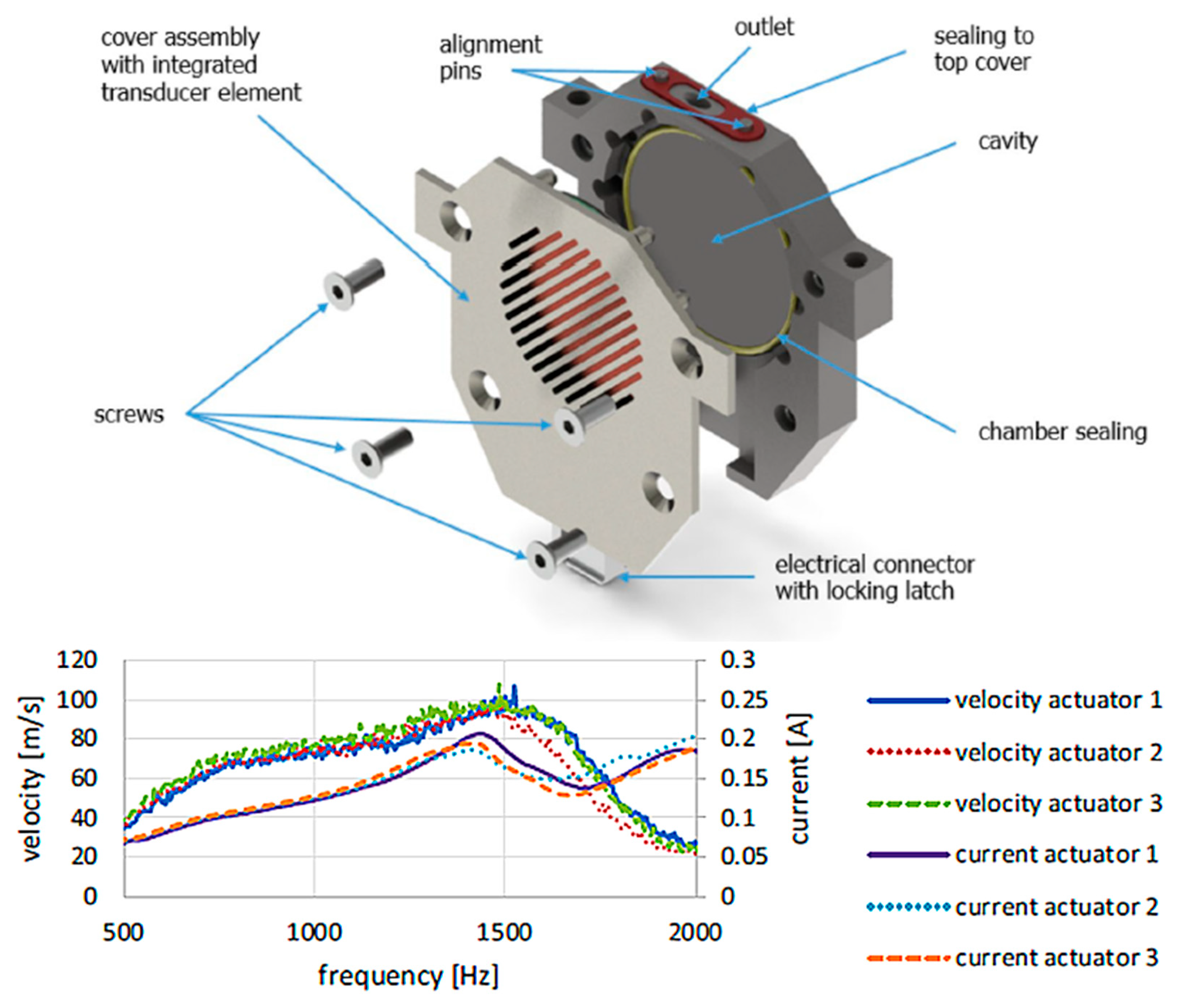
To complete the overview of pulsating flow methodologies, it is relevant to introduce synthetic jets. A synthetic jet actuator (SJA) is a fluidic device that generates a quasi-steady jet through cyclic suction and blowing of fluid into and out of a cavity via an orifice or slot, resulting in zero net mass flow over one actuation cycle. This oscillatory process produces a train of vortical structures that interact with the external flow [58]. The effectiveness of synthetic jets arises from the alternating blowing and suction phases: momentum is injected into the external flow during blowing, while the suction phase perturbs and restructures the shear layer. This leads to enhanced mixing, reduced recirculation, and increased base pressure, promoting flow reattachment. Despite the zero-net-mass-flux condition, a net momentum transfer is achieved through vortex shedding and entrainment, allowing synthetic jets to reproduce many of the benefits of steady or pulsed blowing with significantly lower momentum input. Accordingly, their effectiveness is governed by the momentum coefficient rather than the mass flow rate. The key advantages of SJAs include fast response time, high jet velocity, no requirement for external air supply, absence of complex piping, and compactness, which have attracted significant attention in recent years. A relevant design approach relies on Helmholtz-resonator-type cavities, enabling efficient coupling between actuator dynamics and the fluidic response. Schueller et al. [59] investigated synthetic jet actuators based on this configuration combined with a dual-transducer concept. Their results showed that operating near the resonant frequency significantly enhances actuator efficiency and jet momentum. In particular, the use of two transducers led to an increase in jet exit velocity of up to 50% compared to a single-transducer setup, with peak velocities approaching 90 m/s under certain actuation conditions. This demonstrates the strong potential of resonant, multi-actuator configurations for applications requiring high momentum injection and efficient energy conversion. Recent studies further highlight both the performance potential and the design challenges of these devices. In particular, Weigel et al. [60] developed a compact synthetic jet actuator specifically designed for flow separation control, based on a cavity–orifice configuration driven by a piezoelectric diaphragm.
Their design focuses on achieving high jet velocities while maintaining low power consumption and structural simplicity. The actuator integrates a carefully optimized cavity geometry and slot configuration to maximize the expelled momentum, resulting in jet velocities almost exceeding 100 m/s (Figure 3).
These actuators operate under a zero-net-mass-flux condition, meaning that the mass flow rate averaged over one cycle is zero (i.e., c q = 0 ), while a finite momentum flux is still generated. Accordingly, the appropriate parameter to characterize their intensity is the momentum coefficient c μ , rather than the mass flow rate coefficient.
For synthetic jets, Kourta et al. [61] defined c μ based on the cycle-averaged momentum flux as
C µ = ρ j U j 2 ∑ j ρ ∞ V ∞ 2 S ∞
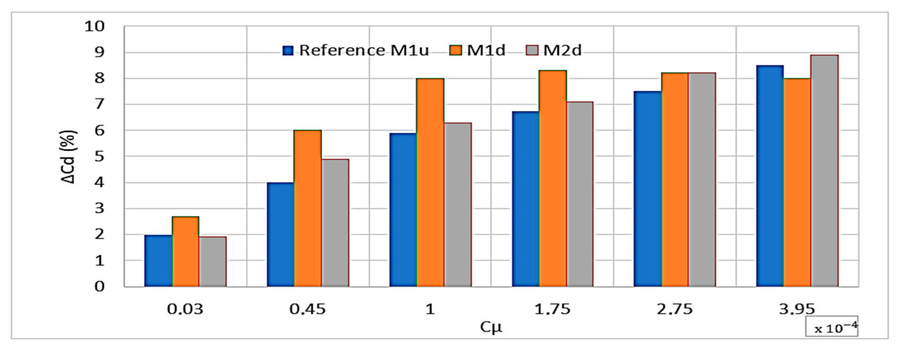
where U j m is the speed’s amplitude of the synthetic jet, ∑ j is the slot synthetic area and S ∞ is the reference body surface. Kourta et al. [61] applied this methodology to the Ahmed body by integrating an array of synthetic jets on the rear slant, reporting drag reductions of up to 8.5% at R e = 1.2 × 10 6 . Their results demonstrate the strong dependence of the drag coefficient on the momentum coefficient: the drag reduction increases with c μ up to a maximum of approximately 8.5%, after which a plateau is reached, indicating a saturation of the control effect (Figure 4).
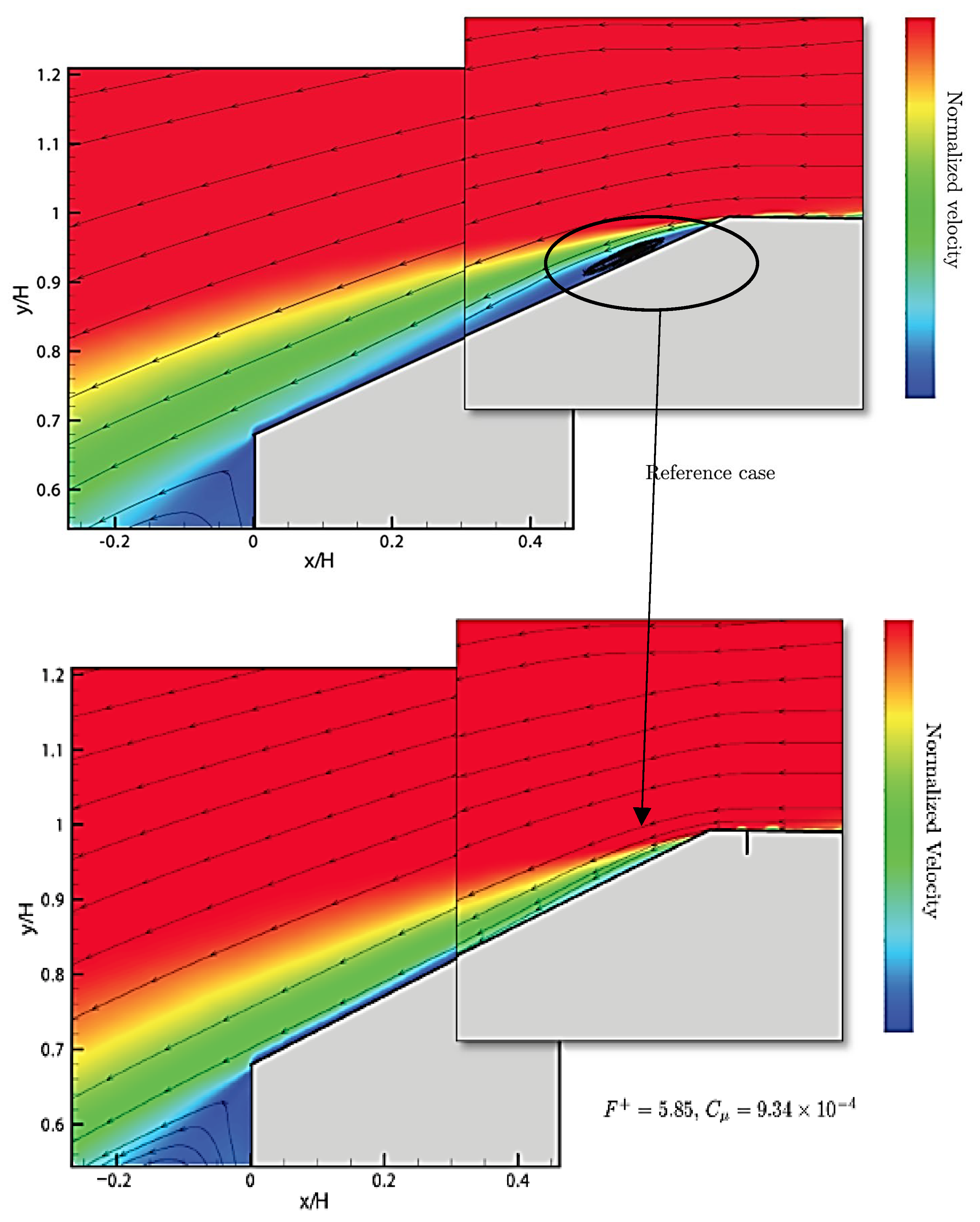
Furthermore, the effectiveness of the control is strongly influenced by the actuator location. While downstream configurations can yield slightly higher peak drag reductions under specific actuation conditions (M2d), the actuator positioned near the onset of separation (M1d) provides more robust and consistent performance, reaching optimal efficiency at lower momentum coefficients and over a broader range of operating parameters. Flow visualizations further show that, in the uncontrolled case, a large recirculation region develops over approximately 86% of the rear slant, characterized by a saddle point located at z / H A ≈ 0.74 . When control is applied, the flow becomes significantly more organized and fully reattached along the slant. Park et al. [62] extended this analysis by investigating different slant angles (25° and 35°) and jet orientations, confirming drag reduction for the 25° configuration and an increase in drag for the 35° case, in agreement with the classical findings of Ahmed. This behavior is associated with the formation of streamwise vortices that alter the wake structure. Similarly, Tounsi et al. [63] confirmed these trends and provided detailed wake topology measurements using Particle Image Velocimetry (PIV), showing that the recirculation bubble can be completely suppressed when flow control is applied (Figure 5) with a drag reduction of almost 10%.
To complete the overview of steady and unsteady flow control methods, it is worth mentioning the numerical investigation carried out by Edwige et al. [64] on the square-back Ahmed body; the authors performed a comparative analysis of steady blowing, pulsed blowing/suction, and synthetic jets using Large Eddy Simulations (LESs). The results confirm the effectiveness of active flow control, with comparable drag reductions across the different techniques, although unsteady actuation demonstrates superior performance.
In particular, synthetic jets achieved drag reductions of up to 8% at an actuation frequency of 400 Hz. Moreover, this technique offers a practical advantage, as it does not require a continuous external air supply, making it especially attractive for real-world applications. Moreover, it should be noted that piezoelectric-driven synthetic jets can offer high efficiency; although they require relatively high driving voltages, their predominantly capacitive behavior results in low current levels and limited power consumption. However, electromagnetic compatibility (EMC) issues may arise, particularly at high operating frequencies.

2.1.4. CoFlow

In the automotive field, there is a growing interest in the application of the Co-Flow Jet (CFJ) technique, as demonstrated by the computational study of Derghal et al. [65]. Their work investigates the effect of coupled suction and blowing slots arranged along the rear slant of an Ahmed body, varying key parameters such as the streamwise positions of the suction ( L a ) and blowing ( L b ) slots, the jet angle ( Φ ), and the jet velocity ( V j ), at a freestream velocity of 40 m/s corresponding to a Reynolds number of 4.29 × 10 6 .
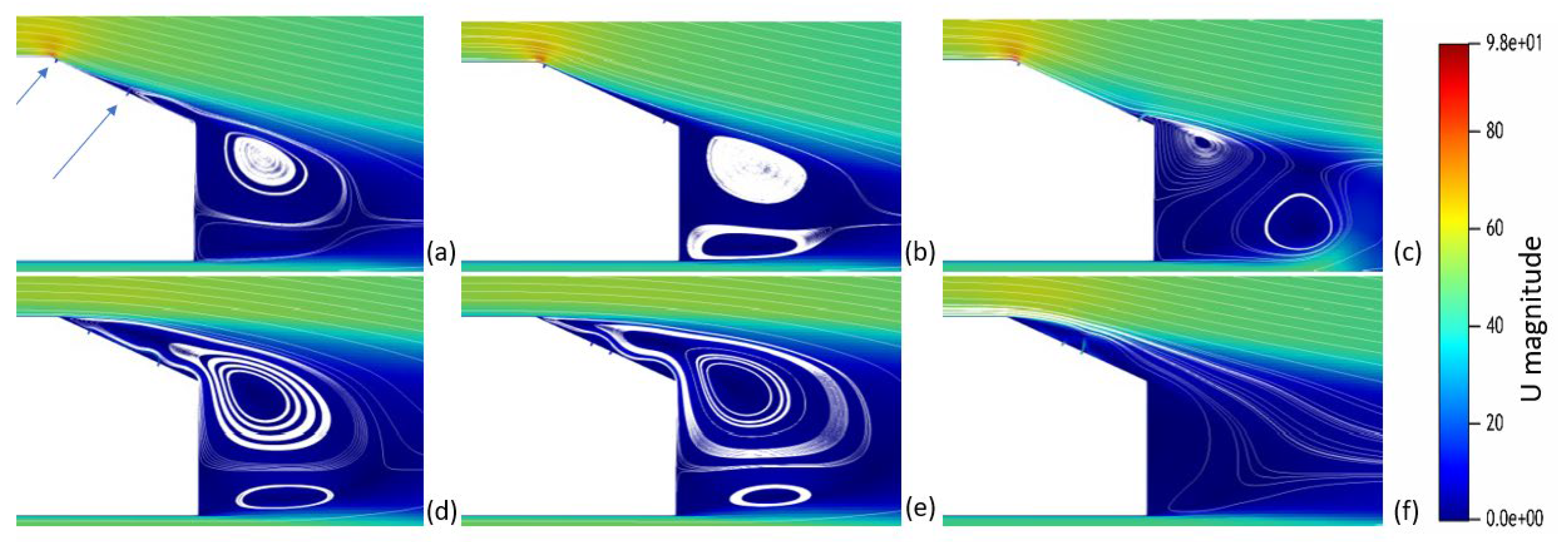
Figure 6 illustrates some of the results obtained when changing the position of the suction and blowing slots.
The results demonstrate a strong sensitivity of the flow control performance to the relative positioning of the suction and blowing slots. In particular, the configuration denoted as CFJ14 yielded the best aerodynamic performance, corresponding to the maximum separation distance between the two slots (Figure 7). Under these conditions, and for a jet velocity of 40 m/s, a drag reduction of approximately 7% was achieved compared to the baseline configuration. This improvement is attributed to the enhanced momentum exchange induced by the co-flow jet, which delays flow separation and promotes a more attached flow over the rear slant, thereby increasing base pressure and reducing pressure drag. A complementary experimental investigation was conducted by Jahanmiri et al. [66], where an Ahmed body was equipped with a suction slot on the upper rear slant and a blowing slot at the base. The study reported drag reductions of up to approximately 4%, with good agreement between experimental measurements and numerical predictions. The results indicate that increasing suction strength enhances drag reduction, particularly when combined with base blowing.
Moreover, for a fixed-control flow rate, improved performance is achieved by reducing the suction slot area while increasing the base blowing area, highlighting the importance of properly distributing the injected and extracted mass flow.

2.2. Surface-Based Active Flow Control and Morphing

Up to this point, aerodynamic performance has been discussed mainly in relation to fluidic-based techniques involving jet injection and suction.

2.2.1. Surface-Based

Comparable results in reduction in drag can also be achieved using mechanically actuated surfaces capable of injecting momentum directly into the boundary layer. This class of techniques is generally referred to as Moving Surface Boundary-Layer Control (MSBC).
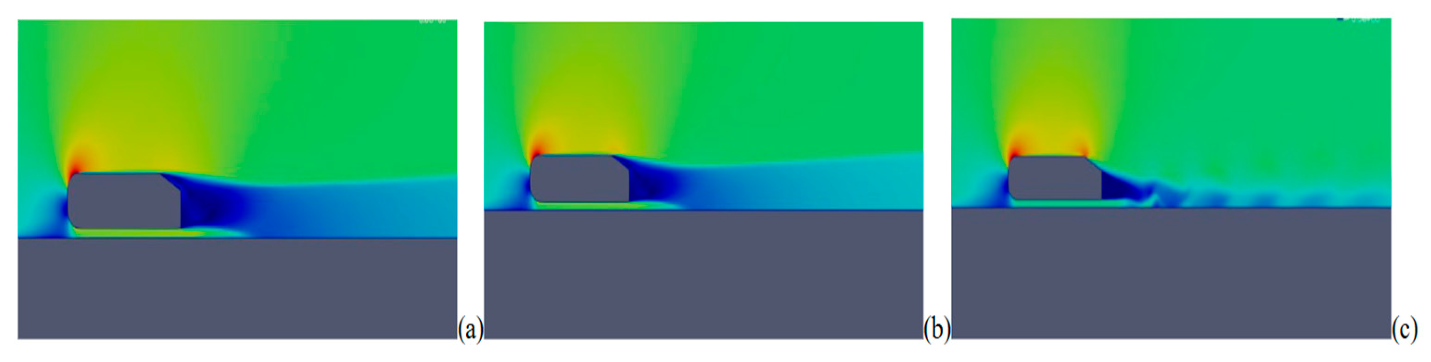
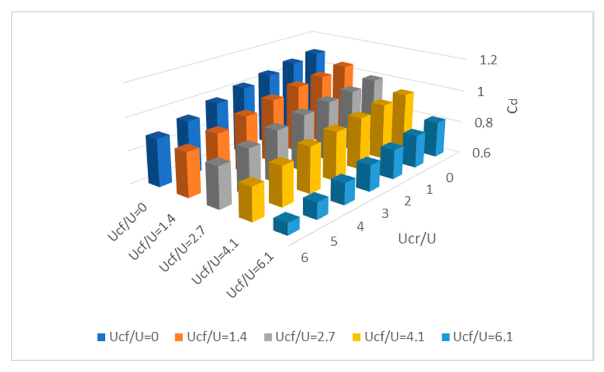
Modi et al. [67,68] conducted extensive experimental investigations on rotating-cylinder actuators applied to airfoils, flat plates, and bluff bodies, with particular emphasis on heavy-duty vehicle configurations. Their results showed that operating the cylinders significantly altered the near-wall momentum distribution, leading to an impressive drag reduction of up to 22% in truck-like geometries (Figure 8).
Complementary computational analyses carried out by Singh et al. [69] confirmed these findings, reporting drag reductions of approximately 35%, with a strong dependence on the linear velocity of the rotating cylinders relative to the incoming flow, as found by Modi et al. [67].

2.2.2. Morphing

Morphing technologies represent an advanced evolution of surface-based flow control, enabling adaptive aerodynamic shapes under varying operating conditions. Originally developed in the aerospace field, early research focused on compliant mechanisms and adaptive structures capable of achieving smooth geometric variations without introducing aerodynamic discontinuities, as shown by Kota et al. [70]. These concepts were further consolidated through comprehensive studies demonstrating the potential of morphing aircraft to enhance lift-to-drag performance, delay flow separation, and improve operational flexibility. In particular, Sofla et al. [71] and Barbarino et al. [72] provided systematic classifications of morphing technologies and their aerodynamic benefits. The development of compliant and adaptive structures has also been investigated in European research, particularly through the work of Monner [73], who showed the feasibility of form-variable trailing edge structures capable of achieving smooth camber variation while maintaining structural integrity. These results highlight the potential of distributed structural compliance for aerodynamic load control and performance enhancement. These concepts have been further consolidated through more recent studies on morphing wing modeling and analysis. Li et al. [74] provided a comprehensive review of modeling strategies for morphing wings, highlighting the importance of multidisciplinary approaches combining structural mechanics, aerodynamics, and control. Their work emphasized the role of aeroelastic coupling and numerical methods in enabling accurate prediction and optimization of morphing configurations. More recent developments have extended these concepts to leading-edge morphing configurations. Wang et al. [75] presented the design optimization and experimental validation of a seamless morphing leading edge for large civil aircraft, demonstrating the feasibility of continuous surface deformation in high-lift devices. Their results confirm that morphing concepts can be effectively applied to both trailing and leading-edge regions, enabling continuous surface adaptation across the wing.
Subsequent developments introduced structurally integrated actuation and smart materials, enabling more compact and efficient morphing solutions. Sun et al. [76] emphasized the role of smart materials in distributed actuation, reporting actuation strains up to approximately 8% for Shape Memory Alloys, with lower values typically adopted in cyclic applications to ensure durability. Chu et al. [77] and Zhu et al. [78] further incorporated advanced design methodologies, numerical modeling, and control strategies, showing that morphing configurations can improve aerodynamic efficiency and delay flow separation under off-design conditions. A significant step toward practical implementation is represented by the Adaptive Compliant Trailing Edge (ACTE) program, developed by NASA in collaboration with Air Force Research Laboratory and FlexSys. Flight-test campaigns reported by Cumming et al. [79] demonstrated operation under realistic conditions, including Mach numbers up to approximately 0.75–0.85 and altitudes up to 40,000 ft, with trailing-edge deflections ranging from −2° to +30°. Experimental results showed good agreement between predicted and measured aerodynamic loads, with discrepancies on the order of a few percent depending on operating conditions. Additional investigations by Herrera et al. [80] confirmed structural integrity and airworthiness, while Cruz et al. [81] and Miller et al. [82] validated load predictions and hinge moment estimations, reporting deviations as low as a few percent in flight conditions.
Modern control-oriented frameworks have further improved the feasibility of morphing systems by enabling stable and adaptive operation under varying flight conditions [83]. Overall, these developments reflect the evolution from mechanically driven concepts to integrated morphing systems based on distributed actuation and structural compliance.
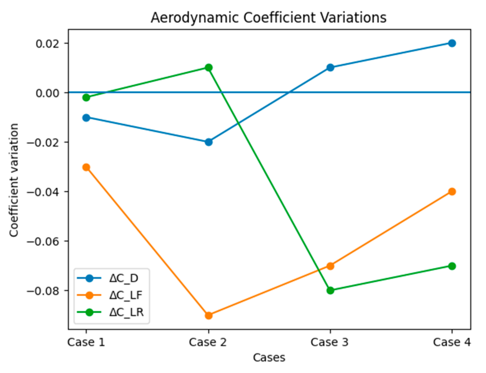
Despite their extensive development in aerospace engineering, morphing technologies remain relatively uncommon in the automotive sector. This is primarily due to the effectiveness and simplicity of passive aerodynamic devices, such as vortex generators and fixed appendages, which provide satisfactory drag reduction without introducing additional mechanical complexity. It should be noted that most automotive implementations rely on discrete movable components rather than continuous surface deformation and therefore differ from strict morphing concepts. Various notable automotive applications have been reported. Kang et al. [84] investigated a movable rear diffuser applied to a sedan vehicle (Hyundai Sonata), testing multiple configurations across a speed range between 70 and 160 km/h using CFD. The arc-plate diffuser geometry resulted in a drag reduction of approximately 7% in simulations and 5.2% in full-scale road testing for the arc plate shape, along with a significant improvement in vehicle stability due to increased downforce generation. Active aerodynamics have found broader application in the supercar and hypercar segments, where performance optimization outweighs cost and complexity considerations. Meder et al. [85] presented the Porsche Active Aerodynamics (PAA) system, designed to maintain an optimal aerodynamic balance between the front and rear axles under varying driving conditions. The system operates in two primary modes: a low-drag “Speed” mode, characterized by nearly neutral downforce (~9 kg), and a high-downforce “Performance” mode, delivering over 130 kg of vertical load. Experimental data indicate a lap-time improvement of approximately 2 s on the North Loop Nürburgring Nordschleife, highlighting the tangible impact of active aerodynamic control. Similarly, Estrada [86] reported the application of advanced active aerodynamic devices in Mercedes-AMG vehicles, combining dynamic front and rear surfaces to enhance handling, braking stability, and cornering performance, where a combination of aerodynamics solutions again helps to push the boundaries of their sports vehicles with a similar approach made by Meder et al. [85]. Figure 9 shows the changes in vehicle drag, front and rear axle downforce depending on the geometric setup of the vehicle in various driving conditions.
The results show that deployment of the active underbody profile leads to an improvement in drag performance; however, it also alters the aerodynamic balance by inducing lift on the rear axle. When the rear wing is deployed, the rear downforce is recovered and further increased, as expected, at the expense of a moderate drag penalty. Finally, opening the frontal louvers results in an additional increase in drag accompanied by a reduction in overall downforce capability, making this configuration aerodynamically inefficient. Based on the data presented, the baseline configuration appears to be the most suitable for road usage, whereas Configuration “C” represents the most promising setup for track-oriented driving. An interesting example is the McLaren P1, where active aerodynamics are integrated with adaptive suspension systems to dynamically control ride height, aerodynamic balance, and overall vehicle performance. The rear wing, a two-axis hydraulically actuated device, is capable of multiple configurations, including partial deployment, full deployment for high-downforce conditions, and forward rotation to function as an aerodynamic brake during deceleration. In parallel, the front aerodynamic elements actively redirect the airflow to enhance underbody suction, further contributing to vehicle stability and performance [87]. The McLaren P1 is reported by McLaren to generate approximately 600 kg of downforce through its active aerodynamic system. Although the manufacturer has not published an exact Nürburgring Nordschleife time, it claims a lap below seven minutes, while the Porsche 918 Spyder has set a documented production-car lap of 6 min 57 s on the same circuit. The P1’s hybrid powertrain produces approximately 916 PS compared to 887 PS for the 918 Spyder [88,89]. In automotive applications, vehicles are typically designed to be aerodynamically efficient, with the option to utilize flow control to enhance aerodynamic performance when needed. However, Lamborghini [90] took a different approach with their ALA system (Active Lamborghini Aerodynamics); the ALA system is inspired by the Drag Reduction System (DRS) used in Formula 1 cars, where a movable flap switches between open and closed positions to actively control downforce and drag. In Lamborghini’s implementation, the system manages airflow, specifically at the front splitter and rear wing area, allowing for impressive cornering speeds by increasing lateral grip without compromising straight-line performance (i.e., top speed). In the standard Huracán, total downforce is estimated at around 200 kg, whereas in the Performante version, it reaches approximately 1500 kg—over seven times higher. This significant increase in downforce drastically improves cornering speed; however, without the ALA system, the car would suffer a reduction in straight-line speed. To address this, the ALA system modifies airflow beneath the car via the front splitter and stalls the rear wing, reducing its circulation and, consequently, the induced drag. This innovative system enabled Lamborghini to achieve a Nürburgring lap time of 6:52 with the Huracán Performante (640 PS), beating the Porsche 918 Spyder (887 PS) by five seconds, despite having 247 PS less power than the Porsche. In contrast to these discrete systems, true morphing approaches in the automotive field are still at an early stage of development. One promising direction involves the use of smart materials, such as Shape Memory Alloys (SMAs), which enable continuous surface deformation as a function of temperature. As widely discussed by Jani et al. [91], SMAs exhibit a reversible martensitic phase transformation, allowing the material to recover its original shape upon heating after deformation.
Han et al. [92] proposed an adaptive spoiler concept based on SMA wires embedded within a compliant polymer matrix, enabling smooth and continuous modification of the aerodynamic profile without discrete mechanical components; in this configuration, thermally induced phase transformation generates axial contraction forces, which, when applied eccentrically within the structure, produce bending moments and thus continuous shape deformation. Experimental results demonstrated a significant aerodynamic impact, with the system enabling a transition from lift to downforce and an increase in vertical force exceeding one order of magnitude compared to the undeformed configuration. For instance, at a freestream velocity of 23 m/s, the aerodynamic force varied from approximately +0.3 N (lift) to −4.2 N (downforce), while in a vehicle-mounted configuration at 15 m/s it changed from +1.8 N to −1.75 N. However, this improvement in downforce was accompanied by an increase in drag of approximately 40–50%, highlighting the inherent trade-off between enhanced vehicle stability and overall aerodynamic efficiency.
More recent studies have further explored SMA-based morphing concepts for automotive applications, highlighting their potential for compact integration and adaptive aerodynamic control while also emphasizing challenges related to response time, thermal management, and energy efficiency. Within this context, Rodinò et al. [93] proposed an SMA–polymer composite solution that enhances structural compliance and enables more distributed and controlled deformation, achieving recoverable strains on the order of a few percent (up to ~5%) and deflections up to 20 mm, with good agreement between numerical predictions and experimental results. This approach allows for smooth camber variation and improved aerodynamic adaptability compared to purely discrete actuation systems.
A more application-oriented implementation is presented by Battaglia et al. [94], where SMAs are integrated into automotive aerodynamic devices through a bistable actuation system, focusing on robust actuation and system-level integration. In this case, SMA activation produces a linear stroke of about 5 mm, resulting in an angular variation of approximately 12° and a corresponding displacement of about 40–45 mm. The system enables reliable configuration switching and maintains stable positions without continuous energy input, improving aerodynamic adaptability while minimizing power consumption.
Overall, while true morphing concepts based on continuous surface deformation remain limited in automotive applications, the increasing integration of active aerodynamic systems and smart materials shows a growing interest in adaptive flow control strategies for road vehicles.

2.3. Plasma-Based Active Flow Control

After discussing fluidic and surface-based techniques for modifying aerodynamic performance, we present a relatively recent class of active flow control methods that involves the use of plasma actuators. These devices generate weakly ionized air near the surface to induce momentum into the boundary layer without mechanical moving parts. Early experimental work by Post et al. [95] clearly established the potential of plasma actuation for separation control at high angles of attack, providing the foundation for subsequent developments in both aerospace and automotive applications.
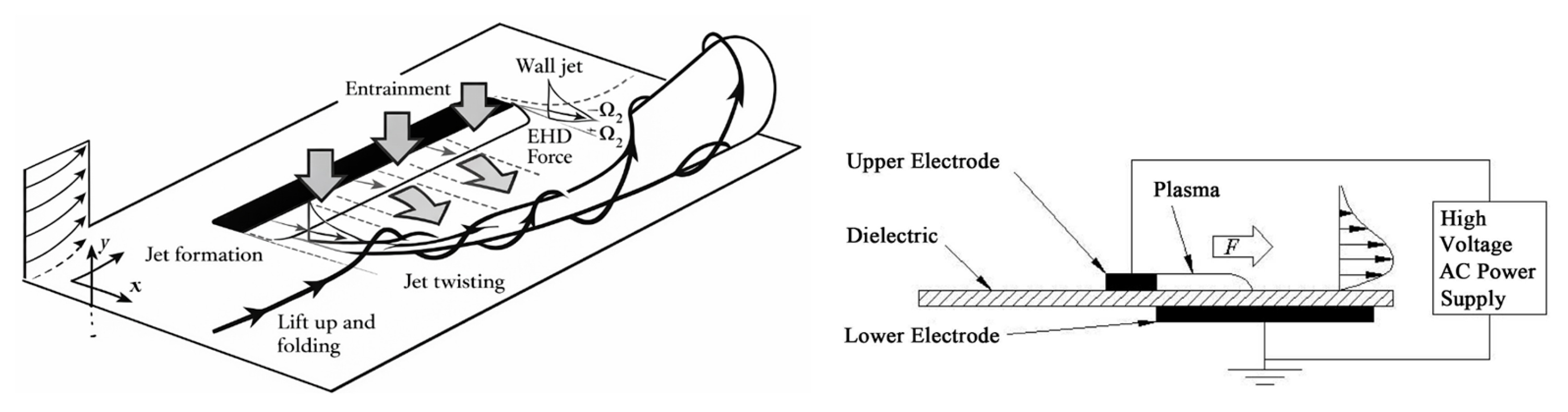
The most widely adopted configuration is the Dielectric Barrier Discharge (DBD) actuator, consisting of two electrodes separated by a dielectric material and embedded flush with the surface. Plasma actuators operate by ionizing air in proximity to the wall, producing an electrohydrodynamic body force that accelerates near-wall fluid, as described by Zhang et al. [96] and Iranshahi et al. [97]. However, it is important to note that the induced ionic wind velocity is typically of the order of a few meters per second, which is significantly lower than the typical freestream velocity in most aerodynamic applications. As a result, plasma actuation does not represent a direct substitute for conventional blowing but rather modifies the near-wall flow structure through relatively weak momentum addition. Several actuator layouts can be employed to influence flow topology. Among them, two dominant configurations are widely discussed in the literature, including by Choi et al. [98]:
  • A longitudinal orientation, where electrodes are aligned with the freestream to directly accelerate the near-wall flow.
  • An orthogonal orientation, in which electrodes are arranged transversely to the external flow to generate streamwise vortices acting similarly to vortex generators.
Overall, AC-DBD plasma actuators either introduce additional momentum into the lower boundary layer or promote mixing through the generation of streamwise vortices that entrain high-momentum fluid toward the wall (Figure 10).
In automotive applications, several studies have investigated the use of AC-DBD actuators for drag reduction and wake control. Boucinha et al. [99] were among the first to conduct a comprehensive investigation of plasma-based flow control on an Ahmed body. Multiple DBD actuator arrays were installed at different locations on the rear slant and edges to assess their influence on separation and wake formation. Their results showed that activating only the top actuator strip led to a drag reduction of approximately 8%, primarily due to improved flow reattachment on the rear slant. Conversely, activating additional actuators along the sides and edges increased wake unsteadiness and turbulence intensity, ultimately negating drag benefits. These results highlight the strong sensitivity of plasma actuation to actuator placement and configuration.
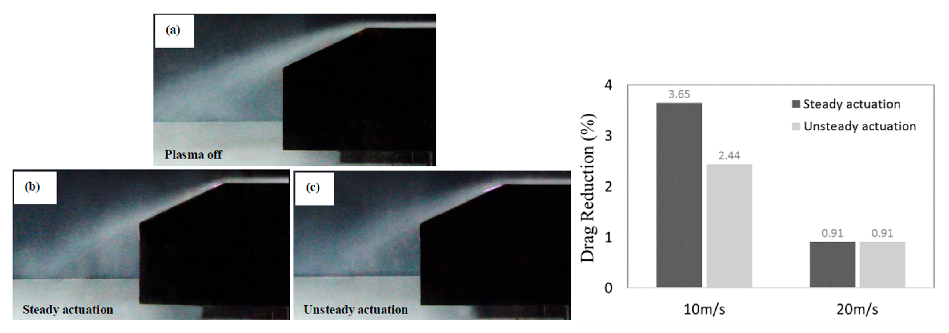
Flow visualizations confirmed a clear downward deflection of the separated shear layer when actuation was active, resulting in a reduced recirculation region and improved pressure recovery. Subsequent studies by Shadmani et al. [100,101] extended this work by comparing steady and unsteady actuation. Their experiments showed a drag reduction of approximately 7% under steady forcing, while pulsed operation achieved around 5%. Further analysis based on pressure distributions indicated that the majority of the drag reduction originated from altered pressure recovery on the rear slanted surface, rather than from modifications of skin friction. Smoke visualization confirmed a significant reduction in the separation bubble under steady forcing, with improved flow attachment along the rear slant. In contrast, unsteady actuation produced weaker effects, particularly at higher freestream velocities, where the control authority of plasma actuation decreased.
However, when the actuator location was shifted toward the center of the rear slant, the drag reduction effect became negligible, emphasizing the high sensitivity of plasma actuation to geometric placement. Moreover, increasing the flow speed reduces the drag-reduction effectiveness of the control methods and leads to increasingly similar results between steady and unsteady actuation, as shown in Figure 11.
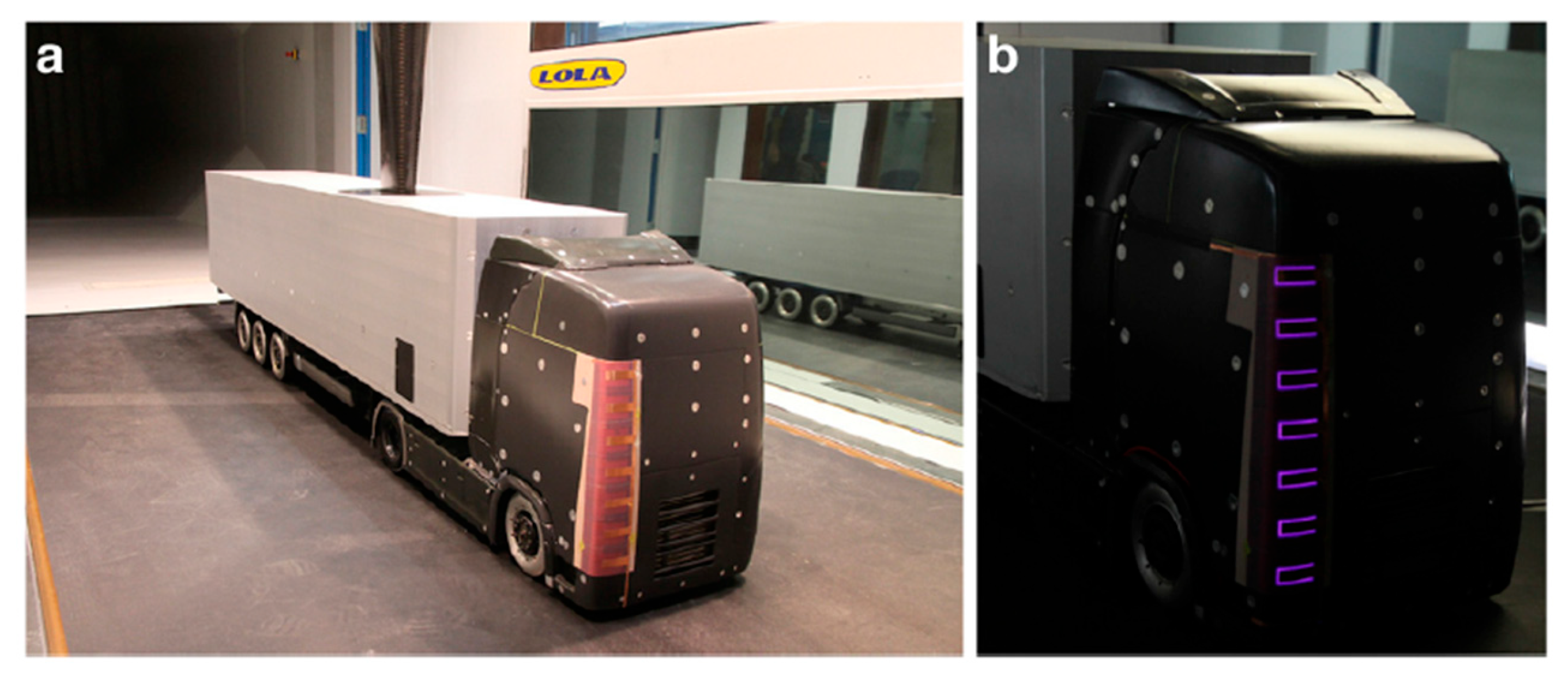
Khalighi et al. [102] explored actuator arrangements on the vertical side edges of the rear surface and reported a drag reduction of up to 21% at 10 m/s. This benefit decreased rapidly with increasing freestream velocity, highlighting an important limitation: as speed increases, the electrohydrodynamic body force becomes insufficient to meaningfully affect the flow field. Similarly, Roy et al. [103] evaluated serpentine and linear electrode designs on a model-scale truck and measured drag reductions of approximately 15% at 60 mph and over 10% at 70 mph. However, when extrapolated to full-scale configurations, the electrical power demand exceeded the vehicular energy savings, raising significant concerns about industrial feasibility. Vernet et al. [104,105] further investigated plasma actuation on a truck model, including configurations on both the tractor and trailer. A particularly relevant result was obtained under crosswind conditions: at a yaw angle of 9° and a wind speed of 10 m/s, drag reductions of up to 20% were measured (Figure 12). Nonetheless, these experiments were conducted at Reynolds numbers far below full-scale conditions, and further validation is required to assess real-world applicability.
Additional studies [106] have explored variations in actuation frequency, electrode geometry, slant angle, and discharge mode (wire-to-plate vs. embedded electrodes). Despite these innovations, the gains obtained were generally comparable to or inferior to those reported by Boucinha et al. [99]. As a result, the practical adoption of plasma actuators in automotive or freight transport remains limited, despite their excellent controllability under laboratory conditions. This limitation is fundamentally linked to the weak scaling of electrohydrodynamic forcing in conventional AC-DBD actuators, which rapidly lose effectiveness as the Reynolds number increases and are therefore unable to significantly alter the global flow field.
These limitations have motivated the development of alternative plasma actuation strategies, among which nanosecond-pulsed DBD (NS-DBD) actuators represent one of the most promising approaches. Instead of generating a quasi-steady ionic wind through electrohydrodynamic forcing, NS-DBD actuation is characterized by rapid energy deposition on nanosecond timescales, leading to localized heating, pressure waves, and strong unsteady perturbations of the flow. Roupassov et al. [107] demonstrated that pulsed nanosecond discharges can effectively control flow separation, achieving significant modifications of the separated shear layer structure and reattachment under conditions where steady forcing is ineffective. Similarly, Little et al. [108] reported substantial aerodynamic improvements in high-lift configurations, including a marked delay of leading-edge separation and lift coefficient increases on the order of 10–20%, depending on actuation conditions. These findings were further supported by Correale et al. [109], who observed enhanced flow attachment and increased mixing in separated regions through pulsed plasma excitation. The underlying physical mechanisms have been extensively discussed by Adamovich et al. [110], who showed that nanosecond surface discharges generate localized temperature rises of several tens of Kelvin and produce compression waves capable of propagating into the outer flow. This leads to a significantly stronger flow response compared to conventional AC-DBD actuators, whose induced velocities are typically limited to a few meters per second. Consequently, NS-DBD actuation is not primarily based on mean momentum addition, but rather on the excitation of natural flow instabilities and the generation of coherent vortical structures that enhance momentum transfer across the shear layer. While the application of NS-DBD actuators in automotive aerodynamics remains limited, recent reviews (e.g., Saemian et al. [111]) indicate that their ability to interact with separated and wake-dominated flows makes them a promising candidate for bluff-body flow control. In particular, the capability of NS-DBD actuation to influence large-scale unsteady structures shows a potential advantage in automotive configurations, where drag is largely governed by wake dynamics and separation phenomena.
This suggests that NS-DBD actuation could partially overcome the intrinsic scaling limitations of AC-DBD actuators in high-Reynolds-number applications. Given the fundamentally different operating principles of AC-DBD and NS-DBD actuators, their key differences in flow control mechanisms are summarized in Table 1.

3. Discussion

3.1. General Considerations

Although active flow control (AFC) techniques offer significant aerodynamic benefits, they inevitably require external energy input. Therefore, a method can be considered viable only when the aerodynamic gain exceeds the associated energy cost under representative operating conditions. However, efficiency alone does not fully determine suitability. In the automotive context, practical implementation must also account for a number of engineering constraints. To assess the feasibility of each AFC technology, the following criteria are adopted:
  • Packaging: ability to integrate the system within the limited available vehicle volume without compromising layout or safety;
  • Ease of operation: simplicity of control logic, robustness, durability, and adaptability to varying operating conditions;
  • Cost: investment and operational costs associated with implementation;
  • Weight: additional mass and its impact on fuel consumption, handling, and braking performance.
These constraints differ significantly between application domains, particularly when comparing automotive and aerospace systems. Table 2 provides a comparison between these two fields, highlighting the more restrictive conditions typical of road vehicles. Automotive flows are typically characterized by lower Reynolds numbers, strong ground effects, and highly transient operating conditions. As a result, AFC systems must operate effectively across a wide range of flow regimes while maintaining robustness and low system complexity. The progressive electrification of vehicles is reshaping the feasibility landscape of AFC technologies. Electrically driven solutions benefit from the increasing availability of onboard power and high-voltage architectures, which facilitate their integration and control. Nevertheless, this technological shift does not uniformly benefit all AFC approaches. More fundamentally, AFC techniques are based on different physical mechanisms, which inherently determine their scalability, efficiency, and integration requirements.
Consequently, the evaluation of each technology must extend beyond aerodynamic effectiveness to include system-level considerations such as power demand, safety, and implementation complexity. From a system-level perspective, packaging, durability, cost, and safety therefore remain the dominant constraints for AFC implementation in production vehicles. These factors, combined with the need for reliable operation under highly variable conditions, strongly differentiate automotive applications from aerospace scenarios, where operating environments are generally more stable and less constrained.

3.2. Fluidic-Blowing and/or Suction

Fluidic actuation based on non-zero mass flow, such as steady blowing and suction, represents one of the most established active flow control (AFC) approaches. These techniques are relatively simple to implement and control, and they do not raise significant regulatory concerns. However, their applicability in automotive systems is fundamentally constrained by low overall efficiency. Energy losses associated with compressors, ducting, and flow distribution considerably reduce the net aerodynamic benefit [112,113], while the need for auxiliary hardware introduces additional penalties in terms of packaging and weight. Consequently, despite their demonstrated effectiveness, steady blowing and suction are unlikely to constitute a scalable solution for production vehicles. The ongoing electrification of vehicles may partially alleviate these limitations, for instance, through the adoption of localized small electric compressors, reducing the need for large centralized compressors, reservoirs, and extensive piping. Nevertheless, system-level efficiency remains a critical issue. Zero-net-mass-flow devices, such as synthetic jets, overcome several of these limitations by eliminating the need for continuous mass injection and complex pneumatic systems, thus enabling more compact and potentially more efficient implementations. Their main drawback lies in the cost and complexity of the required power electronics, particularly to achieve the relatively high actuation voltages required by piezoelectric actuators, typically in the range of 100–300 V and potentially higher depending on performance requirements. However, this constraint is progressively diminishing with the widespread adoption of hybrid and fully electric vehicle platforms, where high-voltage architectures are becoming standard. This technological shift makes synthetic jets inherently well suited for integration into modern vehicle systems. For these reasons, synthetic jets can be regarded as one of the most promising fluidic AFC technologies for automotive applications, offering a favorable balance between aerodynamic performance and system-level feasibility [99,114].

3.3. Profile

Rotating surfaces have proven to be an effective approach for improving aerodynamic performance while requiring limited installation volume and only electrical wiring for operation. Nevertheless, the presence of high-speed rotating components on exposed vehicle surfaces raises substantial safety concerns, making their adoption unlikely in production vehicles due to regulatory constraints associated with the risk of accidental contact.
Morphing surface technologies can be broadly classified into two main categories, depending on the actuation mechanism: mechanically actuated and electrically actuated systems. Mechanical morphing relies on linkages and actuators to physically deform aerodynamic surfaces [100]. This solution is efficient and relatively simple to control, and it does not introduce significant regulatory issues, as the moving components are comparable to conventional automotive mechanisms. However, mechanical morphing systems require considerable packaging volume due to internal kinematic assemblies, resulting in increased weight, structural complexity, and cost. Active aerodynamic devices fall within this category and include real-world implementations such as the adaptive rear wing of the McLaren P1. These systems provide high effectiveness and reliable controllability, enabling real-time optimization of aerodynamic balance, but at the expense of additional actuators, electric motors, and mechanical interfaces, which negatively impact vehicle mass, cost, and integration effort. In contrast, electrically actuated morphing systems induce surface deformation through electric fields or smart materials [115], offering a compact and lightweight solution with reduced mechanical complexity. Depending on the specific actuation technology, these systems can also provide fast response, as in the case of piezoelectric actuators. Their main limitation lies in the cost and complexity of the required power electronics, particularly to achieve relatively high actuation voltages (on the order of ~400 V, depending on the technology). This aspect is especially relevant for smart-material-based solutions such as Shape Memory Alloys (SMAs), where efficient actuation relies on controlled electrical heating. In addition, SMA-based systems may present further challenges related to response time, thermal management, and material fatigue under repeated actuation cycles, which can limit their applicability in high-frequency or long-term operation scenarios. In this context, similarly to what was discussed for synthetic jets, the ongoing transition toward hybrid and fully electric vehicle platforms represents a key enabling factor, as the increasing availability of high-voltage architectures facilitates system integration and reduces the relative impact of power electronics constraints. Consequently, electrically actuated morphing surfaces, particularly those based on smart materials, represent a promising direction for future automotive aerodynamic control, as they offer a favorable compromise between integration, weight reduction, and functional adaptability, especially in applications where continuous surface deformation can provide aerodynamic advantages over discrete actuation systems.

3.4. Plasma

Plasma-based actuation represents a relatively recent active flow control (AFC) approach that enables boundary layer manipulation without moving parts and with minimal integration volume, as actuators are typically embedded flush with the surface. The most widely adopted configuration is the Dielectric Barrier Discharge (DBD or AC-DBD) actuator, which operates by ionizing the air near the wall and generating an electrohydrodynamic body force that accelerates the near-wall flow.
However, the induced ionic wind is typically limited to a few meters per second, making plasma actuation significantly weaker than conventional blowing. As a result, its effect is primarily confined to near-wall flow structures, with limited influence on the outer flow. Experimental studies on simplified automotive geometries have demonstrated measurable drag reductions, mainly associated with improved flow reattachment and wake modification. Nevertheless, these benefits are highly sensitive to actuator placement, configuration, and operating conditions, and may deteriorate or even become detrimental if not properly optimized. From a system-level perspective, plasma actuation presents several limitations. When extrapolated to full-scale applications, the electrical power required for actuation can offset or exceed the aerodynamic gains, reducing overall efficiency. Furthermore, the effectiveness of conventional AC-DBD actuators decreases rapidly with increasing Reynolds number and freestream velocity, making them poorly suited for typical automotive operating conditions. To address these limitations, more advanced concepts such as nanosecond-pulsed DBD (NS-DBD) actuators have been proposed. These systems rely on rapid energy deposition and strong unsteady perturbations, rather than steady momentum addition, enabling improved interaction with separated flows. However, despite their promising performance, their application in automotive systems remains at an early stage, and plasma-based AFC is currently considered limited in terms of large-scale industrial feasibility. In addition, plasma actuators require high-voltage power electronics, typically operating at kilovolt levels, leading to significant cost and integration challenges. Although the ongoing transition toward hybrid and fully electric vehicles partially mitigates this issue through the availability of onboard high-voltage architectures, concerns related to safety, durability, and certification remain, particularly due to the presence of plasma discharges on exposed surfaces.

3.5. Comparative Assessment

Having analyzed both the physical mechanisms (Section 2) and system-level constraints (Section 3), a comparative assessment is now required to identify the most suitable technologies for automotive applications. Table 3 provides a comparative assessment of the main active flow control (AFC) techniques based on key performance and implementation criteria, including drag reduction, power consumption, response time, technological readiness level (TRL), and integration constraints. The qualitative “Overall Assessment” is derived from trends reported in the literature (Section 2 and Section 3) and reflects the relative trade-off between aerodynamic performance and practical feasibility, rather than absolute quantitative values.
While Table 3 presents a qualitative overview derived from trends in the literature (Section 2 and Section 3), Table 4 introduces a decision-oriented assessment, enabling a more direct comparison of the relative suitability of each technology for automotive applications.
The results consistently indicate that synthetic jet actuators and morphing-based solutions offer the most favorable balance between aerodynamic performance and practical feasibility. Synthetic jets combine relatively high efficiency, compactness, and compatibility with electrified vehicle architectures, making them particularly suitable for integration in modern platforms. Similarly, morphing systems, especially electrically actuated configurations, provide effective aerodynamic control with manageable integration constraints, and their feasibility is expected to improve further with the increasing availability of high-voltage systems. In contrast, fluidic techniques based on steady or pulsed blowing, although capable of achieving significant drag reductions, remain penalized by low system-level efficiency, as well as packaging complexity and additional weight associated with auxiliary components. Plasma-based approaches, on the other hand, offer unique advantages in terms of actuation speed and flow responsiveness, particularly for advanced concepts such as NS-DBD actuators. However, their applicability is currently limited by high voltage requirements, integration challenges, and reduced effectiveness at high Reynolds numbers. In automotive applications, the primary aerodynamic performance indicator is typically the drag coefficient, as fuel efficiency and energy consumption are strongly influenced by drag reduction. However, a review of the literature considered in this work reveals that several studies also report meaningful variations in lift (in aerospace contexts) or downforce (in automotive applications). Although these quantities are not consistently reported across all technologies, they provide valuable insight into vehicle stability, handling, and aerodynamic balance.
For this reason, a complementary summary of lift and downforce effects is presented, in a format analogous to the drag comparison (Table 4), allowing a more comprehensive assessment of the aerodynamic impact of the investigated techniques.
The decision matrix (Table 5) further highlights that high-performance solutions such as mechanical morphing or rotating surfaces, while aerodynamically effective, are often constrained by integration, safety, and system complexity considerations.
This table represents one of the key contributions of the present work, as it translates qualitative literature trends into a decision-oriented engineering tool. Overall, the comparison demonstrates that no single AFC technology maximizes all performance metrics simultaneously; instead, the most promising solutions are those that achieve the best compromise between aerodynamic benefits, energy efficiency, and implementation feasibility.

4. Conclusions and Future Trends

This review has examined the most relevant active flow control (AFC) techniques originally developed for aerospace applications and their subsequent adaptation to the automotive sector. Each methodology was assessed in terms of aerodynamic effectiveness, implementation challenges, and technological maturity, supported by a structured comparative framework and a decision-oriented analysis (Table 3, Table 4 and Table 5).
The results consistently indicate that morphing aerodynamic systems and synthetic jet actuators represent the most promising solutions currently available for automotive applications, as they provide the most favorable balance between aerodynamic performance, energy efficiency, and integration feasibility. Morphing technologies, already partially implemented in high-performance vehicles, offer reliable and effective aerodynamic control, while electrically actuated solutions are expected to benefit from the increasing availability of high-voltage architectures. In parallel, synthetic jets emerge as a particularly attractive technology due to their compactness, absence of external air supply, and relatively high efficiency, making them well suited for integration into modern electrified platforms. Fluidic techniques based on steady or pulsed blowing, although capable of achieving significant drag reductions, remain limited by system-level inefficiencies, as well as packaging and weight penalties associated with compressors, ducting, and auxiliary components. As a result, their large-scale implementation in production vehicles remains unlikely without substantial improvements in overall system efficiency.
Plasma-based techniques present a contrasting scenario; conventional AC-DBD actuators are fundamentally limited by the weak scaling of electrohydrodynamic forcing, which results in a rapid loss of effectiveness at increasing Reynolds numbers and freestream velocities. In contrast, nanosecond-pulsed DBD (NS-DBD) actuators rely on a different physical mechanism based on rapid energy deposition, generating pressure waves and strong unsteady perturbations capable of interacting with large-scale flow structures. This enables more effective control of separated and wake-dominated flows, potentially overcoming some of the intrinsic limitations of steady plasma actuation. However, despite their promising aerodynamic performance, NS-DBD systems remain at an early stage of development and are still constrained by high energy requirements, system complexity, and limited experimental validation under full-scale automotive conditions.
More broadly, the evolution of AFC technologies is strongly influenced by the ongoing electrification of vehicles, which facilitates the integration of electrically driven systems and reduces the relative impact of high-voltage power electronics. At the same time, research is progressively shifting from fundamental flow physics toward system-level optimization and real-world applicability, supported by increasing collaboration between academia, industry, and research institutions. In this context, emerging approaches based on Artificial Intelligence, particularly Reinforcement Learning, are receiving increasing attention for real-time closed-loop flow control. These methods enable adaptive optimization of actuation strategies under highly transient operating conditions and have demonstrated promising results in fluid mechanics applications [116,117]. The combination of AFC technologies with advanced control strategies, together with multidisciplinary integration involving aerodynamics, vehicle dynamics, and control engineering, is expected to play a key role in improving robustness, energy efficiency, and scalability. Overall, while several AFC techniques demonstrate strong aerodynamic potential, only a limited subset currently satisfy the combined requirements of performance, efficiency, and feasibility necessary for large-scale implementation in production vehicles. Future developments are likely to focus on hybrid approaches, combining complementary actuation mechanisms with intelligent control strategies, to fully exploit the potential of active flow control in next-generation automotive systems.

Funding

This research received no external funding.

Data Availability Statement

Not applicable.

Acknowledgments

M. D. de Tullio and G. Pascazio were partially supported by the Italian Ministry of Education, University and Research under the Program Department of Excellence Legge 232/2016 (Grant No. CUP-D93C23000100001).

Conflicts of Interest

Authors Marco Robert Herberg and Stefano De Pinto were employed by the company McLaren Automotive Europe SL. The remaining authors declare that the research was conducted in the absence of any commercial or financial relationships that could be construed as a potential conflict of interest.

References

  1. Connolly, M.G.; Ivankovic, A.; O’Rourke, M.J. Drag reduction technology and devices for road vehicles: A comprehensive review. Heliyon 2024, 10, e33757. [Google Scholar] [CrossRef] [Scilit]
  2. Piechna, J. A review of active aerodynamic systems for road vehicles. Energies 2021, 14, 7887. [Google Scholar] [CrossRef] [Scilit]
  3. Modi, V.J.; Fernando, M.S.U.K.; Yokomizo, T. Moving surface boundary-layer control: Studies with bluff bodies and application. AIAA J. 1991, 29, 1400–1406. [Google Scholar] [CrossRef] [Scilit]
  4. Liu, H. Racing car aerodynamics: Optimising vehicle drag reduction and downforce control. In Proceedings of the 2025 2nd International Conference on Electrical Engineering and Intelligent Control (EEIC 2025), Auckland, New Zealand, 3–4 July 2025; Atlantis Press: Dordrecht, The Netherlands, 2025; pp. 837–847. [Google Scholar] [CrossRef] [Scilit]
  5. Katz, J. Aerodynamics in motorsports. Proc. Inst. Mech. Eng. Part P J. Sports Eng. Technol. 2019, 235, 324–338. [Google Scholar] [CrossRef] [Scilit]
  6. Piechna, J.; Kurec, K.; Broniszewski, J.; Remer, M.; Piechna, A.; Kamieniecki, K.; Bibik, P. Influence of the car movable aerodynamic elements on fast road car cornering. Energies 2022, 15, 689. [Google Scholar] [CrossRef] [Scilit]
  7. Gad-el-Hak, M. Flow Control: Passive, Active, and Reactive Flow Management; Cambridge University Press: Cambridge, UK, 2000. [Google Scholar]
  8. Ravelli, U.; Ravelli, S. An overview of drag reduction methods in road cars. Fluid Dyn. Mater. Process. 2026, 22, 1. [Google Scholar] [CrossRef] [Scilit]
  9. Sudin, M.N.; Abdullah, M.; Shamsudin, S.; Faiz, R.; Tahir, M. Review of research on vehicles aerodynamic drag reduction methods. Int. J. Mech. Mechatron. Eng. 2014, 14, 35–47. [Google Scholar]
  10. Cattafesta, L.N.; Sheplak, M. Actuators for active flow control. Annu. Rev. Fluid Mech. 2011, 43, 247–272. [Google Scholar] [CrossRef] [Scilit]
  11. Ahmed, S.R.; Ramm, G.; Faltin, G. Some salient features of the time-averaged ground vehicle wake. SAE Trans. 1984, 93, 473–503. [Google Scholar] [CrossRef] [Scilit]
  12. Brunn, A.; Wassen, E.; Sperber, D.; Nitsche, W.; Thiele, F. Active drag control for a generic car model. In Proceedings of the Active Flow Control 2006, Berlin, Germany, 27–29 September 2006; Springer: Berlin/Heidelberg, Germany, 2026; pp. 247–259. [Google Scholar]
  13. Jahanmiri, M. Active Flow Control: A Review; Chalmers University of Technology: Göteborg, Sweden, 2010. [Google Scholar]
  14. Maine, M.; Oumami, E.M.; Bouksour, O.; Tizliouine, A. Review of research on cars wake flow control methods to reduce aerodynamic drag. Int. J. Innov. Appl. Stud. 2019, 25, 1069–1089. [Google Scholar]
  15. Mukuk, M.I.; Abedin, M.Z. Review on aerodynamic drag reduction of vehicles. Int. J. Eng. Mater. Manuf. 2019, 4, 1–14. [Google Scholar] [CrossRef] [Scilit]
  16. Heft, A.I.; Indinger, T.; Adams, N.A. Introduction of a New Realistic Generic Car Model for Aerodynamic Investigations. Technical Report. In Proceedings of the SAE 2012 World Congress & Exhibition, Detroit, MI, USA, 24 April 2012. [Google Scholar] [CrossRef] [Scilit]
  17. Heft, A.; Indinger, T.; Adams, N.A. Experimental and numerical investigation of the DrivAer model. In Proceedings of the ASME 2012 Fluids Engineering Division Summer Meeting, Rio Grande, PR, USA, 8–12 July 2012. [Google Scholar] [CrossRef] [Scilit]
  18. Varney, M.; Passmore, M.; Wittere, F.; Kuthada, T. Experimental data for the validation of numerical methods: DrivAer model. Fluids 2020, 5, 236. [Google Scholar] [CrossRef] [Scilit]
  19. Cho, J.; Park, J.; Yee, K.; Kim, H.-L. Comparison of various drag reduction devices and their aerodynamic effects on the DrivAer model. SAE Int. J. Passeng. Cars Mech. Syst. 2018, 11, 225–237. [Google Scholar] [CrossRef] [Scilit]
  20. Ashton, N.; Van Noordt, W. Overview and summary of the first automotive CFD prediction workshop: DrivAer model. SAE Int. J. Commer. Veh. 2023, 16, 61–85. [Google Scholar] [CrossRef] [Scilit]
  21. Ashton, N.; Mockett, C.; Fuchs, M.; Fliessbach, L.; Hetmann, H.; Knacke, T.; Schonwald, N.; Skaperdas, V.; Fotiadis, G.; Walle, A.; et al. DrivAerML: High-fidelity computational fluid dynamics dataset for road-car external aerodynamics. arXiv 2024, arXiv:2408.11969. [Google Scholar] [CrossRef] [Scilit]
  22. Ashton, N.; Revell, A. Comparison of RANS and DES Methods for the DrivAer Automotive Body; Technical Report; SAE International: Detroit, MI, USA, 2015. [Google Scholar] [CrossRef] [Scilit]
  23. Wang, S.; Avadiar, T.; Thompson, M.C.; Burton, D. Effect of moving ground on the aerodynamics of a generic automotive model: The DrivAer-estate. J. Wind Eng. Ind. Aerodyn. 2019, 195, 104000. [Google Scholar] [CrossRef] [Scilit]
  24. Wolf, T. The aerodynamic development of the new Porsche Cayenne. Proc. Inst. Mech. Eng. Part D J. Automob. Eng. 2020, 234, 390–408. [Google Scholar] [CrossRef] [Scilit]
  25. Phan, T.-L.; Pham, Q.T.; Nguyen, T.K.L.; Nguyen, T.T. A numerical analysis of active flow control techniques for aerodynamic drag reduction in the square-back Ahmed model. Appl. Sci. 2023, 13, 239. [Google Scholar] [CrossRef] [Scilit]
  26. Ho, H.H.; Shirinzad, A.; Essel, E.E.; Sullivan, P.E. Synthetic jet actuators for active flow control: A review. Fluids 2024, 9, 290. [Google Scholar] [CrossRef] [Scilit]
  27. Dano, B.P.E.; Kirk, D.; Zha, G.-C. Experimental investigation of jet mixing of a co-flow jet airfoil. In Proceedings of the 5th AIAA Flow Control Conference, Chicago, IL, USA, 28 June–1 July 2010. [Google Scholar] [CrossRef] [Scilit]
  28. Brunet, V.; Dandois, J.; Verbeke, C. Recent Onera Flow Control Research on High-Lift Configurations. Aerosp. Lab 2013, 6, 1–12. [Google Scholar]
  29. Rouméas, M.; Gilliéron, P.; Kourta, A. Drag reduction by flow separation control on a car after body. Int. J. Numer. Methods Fluids 2009, 60, 1222–1240. [Google Scholar] [CrossRef] [Scilit]
  30. Harinaldi, H.; Budiarso, B.; Warjito, W.; Kosasih, E.A.; Tarakka, R.; Simanungkalit, S.P.; Teryanto, L.; Fredy, I.G.M. Modification of flow structure over a van model by suction flow control to reduce aerodynamic drag. Makara J. Technol. 2012, 16, 3. [Google Scholar] [CrossRef] [Scilit]
  31. Tarakka, R.; Salam, N.; Jalaluddin Rauf, W.; Ihsan, M. Aerodynamic drag reduction on the application of suction flow control on vehicle model with varied upstream velocity. IOP Conf. Ser. Mater. Sci. Eng. 2021, 1173, 012045. [Google Scholar] [CrossRef] [Scilit]
  32. Godard, G.; Stanislas, M. Control of a decelerating boundary layer. Part 1: Optimization of passive vortex generators. Aerosp. Sci. Technol. 2006, 10, 181–191. [Google Scholar] [CrossRef] [Scilit]
  33. Godard, G.; Foucaut, J.M.; Stanislas, M. Control of a decelerating boundary layer. Part 2: Optimization of slotted jets vortex generators. Aerosp. Sci. Technol. 2006, 10, 394–400. [Google Scholar] [CrossRef] [Scilit]
  34. Godard, G.; Stanislas, M. Control of a decelerating boundary layer. Part 3: Optimization of round jets vortex generators. Aerosp. Sci. Technol. 2006, 10, 455–464. [Google Scholar] [CrossRef] [Scilit]
  35. Radespiel, R.; Burnazzi, M.; Casper, M.; Scholz, P. Active flow control for high lift with steady blowing. Aeronaut. J. 2016, 120, 171–200. [Google Scholar] [CrossRef] [Scilit]
  36. Mestiri, R.; Ahmed-Bensoltane, A.; Keirsbulck, L.; Aloui, F.; Labraga, L. Active Flow Control at the Rear End of a Generic Car Model Using Steady Blowing. J. Appl. Fluid Mech. 2014, 7, 217–252. [Google Scholar] [CrossRef] [Scilit]
  37. Aubrun, S.; McNally, J.; Alvi, F.; Kourta, A. Separation flow control on a generic ground vehicle using steady microjet arrays. Exp. Fluids 2011, 51, 1177–1187. [Google Scholar] [CrossRef] [Scilit]
  38. Littlewood, R.P.; Passmore, M.A. Aerodynamic drag reduction of a simplified squareback vehicle using steady blowing. Exp. Fluids 2012, 53, 519–529. [Google Scholar] [CrossRef] [Scilit]
  39. McNally, J.; Fernandez, E.; Robertson, G.; Kumar, R.; Taira, K.; Alvi, F.; Yamaguchi, Y.; Murayama, K. Drag reduction on a flat-back ground vehicle with active flow control. J. Wind Eng. Ind. Aerodyn. 2015, 145, 292–303. [Google Scholar] [CrossRef] [Scilit]
  40. Zhang, B.F.; Liu, K.; Zhou, Y.; To, S.; Tu, J.Y. Active drag reduction of a high-drag Ahmed body based on steady blowing. J. Fluid Mech. 2018, 856, 351–396. [Google Scholar] [CrossRef] [Scilit]
  41. Wassen, E.; Thiele, F. Drag reduction for a generic car model using steady blowing. In Proceedings of the 4th AIAA Flow Control Conference, Seattle, WA, USA, 23–26 June 2008. [Google Scholar] [CrossRef] [Scilit]
  42. Wassen, E.; Thiele, F. Road vehicle drag reduction by combined steady blowing and suction. In Proceedings of the 39th AIAA Fluid Dynamics Conference, San Antonio, TX, USA, 22–25 June 2009. [Google Scholar] [CrossRef] [Scilit]
  43. Huminic, A.; Huminic, G. Automotive wing with active control of flow. UPB Sci. Bull. Ser. D 2014, 76, 231–238. [Google Scholar]
  44. Englar, R. Improved Pneumatic Aerodynamics for Drag Reduction, Fuel Economy, Safety and Stability Increase for Heavy Vehicles; Technical Report; SAE International: Warrendale, PA, USA, 2005. [Google Scholar] [CrossRef] [Scilit]
  45. Bardera, R.; Matías-García, J.C.; Barroso-Barderas, E.; Fernández-Antón, J.; Rodríguez-Sevillano, A.A. Active Flow Control by Coanda Actuators for Aerodynamic Drag Reduction in a European-Type Truck. Actuators 2025, 14, 556. [Google Scholar] [CrossRef] [Scilit]
  46. Ramadhan, R.D.R.; Mat, S.; Samin, P.M.; Othman, N.; Wahid, M.A. Review on flow controls for vehicles aerodynamic drag reduction. J. Adv. Res. Fluid Mech. Therm. Sci. 2022, 10, 11–36. [Google Scholar] [CrossRef] [Scilit]
  47. Greenblatt, D.; Wygnanski, I. The Control of Flow Separation by Periodic Excitation. Prog. Aerosp. Sci. 2000, 36, 487–545. [Google Scholar] [CrossRef] [Scilit]
  48. Whalen, E.A.; Shmilovich, A.; Spoor, M.; Tran, J.; Vijgen Paul Lin, J.C.; Andino, M. Flight Test of an Active Flow Control Enhanced Vertical Tail. AIAA J. 2018, 56, 3393–3398. [Google Scholar] [CrossRef] [Scilit]
  49. Pastoor, M.; Henning, L.; Noack, B.; King, R.; Tadmor, G. Feedback shear layer control for bluff body drag reduction. J. Fluid Mech. 2008, 608, 161–196. [Google Scholar] [CrossRef] [Scilit]
  50. Henning, L.; King, R. Robust Multivariable Closed-Loop Control of a Turbulent Backward-Facing Step Flow. J. Aircr. 2007, 44, 201–208. [Google Scholar] [CrossRef] [Scilit]
  51. Choi, H.; Jeon, W.; Kim, J. Control of Flow Over a Bluff Body. Annu. Rev. Fluid Mech. 2008, 40, 113–139. [Google Scholar] [CrossRef] [Scilit]
  52. Pfeiffer, J. Closed-Loop Active Flow Control for Road Vehicles Under Unsteady Cross-Wind Conditions. Doctoral Thesis, Technische Universität Berlin, Berlin, Germany, 2016. [Google Scholar] [CrossRef] [Scilit]
  53. Joseph, P.; Amandolèse, X.; Aider, J.L. Drag reduction on the 25° slant angle Ahmed reference body using pulsed jets. Exp. Fluids 2012, 52, 1169–1185. [Google Scholar] [CrossRef] [Scilit]
  54. Joseph, P.; Amandolese, X.; Edouard, C. Flow control using MEMS pulsed micro-jets on the Ahmed body. Exp. Fluids 2013, 54, 1442. [Google Scholar] [CrossRef] [Scilit]
  55. He, K.; Minelli, G.; Su, X.; Huang, N.; Krajnović, S. Active wake-flow control for a notchback Ahmed body driven by a genetically inspired optimization. J. Fluid Mech. 2024, 1000, A20. [Google Scholar] [CrossRef] [Scilit]
  56. Bideaux, E.; Bobillier, P.; Fournier, E.; Gilliéron, P.; El Hajem, M.; Champagne, J.; Gilotte, P.; Kourta, A. Drag reduction by pulsed jets on strongly unstructured wake: Towards the square-back control. Int. J. Aerodyn. 2011, 1, 282–298. [Google Scholar] [CrossRef] [Scilit]
  57. Gilliéron, P.; Kourta, A. Aerodynamic drag control by pulsed jets on simplified car geometry. Exp. Fluids 2013, 54, 1457. [Google Scholar] [CrossRef] [Scilit]
  58. Ja’fari, M.; Shojae, F.J.; Jaworski, A.J. Synthetic jet actuators: Overview and applications. Int. J. Thermofluids 2023, 20, 100438. [Google Scholar] [CrossRef] [Scilit]
  59. Schueller, M.; Wiegel, P.; Lipowski, M.; Schulze, R.; Otto, T.; Gessner, T. Development and test of synthetic jet actuators based on dual transducer concept. In Proceedings of the Industrial and Commercial Applications of Smart Structures Technologies 2014, San Diego, CA, USA, 11–12 March 2014. [Google Scholar] [CrossRef] [Scilit]
  60. Weigel, P.; Schueller, M.; Gratias, A.; Lipowski, M.; Meer, T.; Bardet, M. Design of a synthetic jet actuator for flow separation control. CEAS Aeronaut. J. 2020, 11, 813–821. [Google Scholar] [CrossRef] [Scilit]
  61. Kourta, A.; Leclerc, C. Characterization of synthetic jet actuation with application to Ahmed body wake. Sens. Actuators A Phys. 2013, 192, 13–26. [Google Scholar] [CrossRef] [Scilit]
  62. Park, H.; Cho, J.H.; Lee, J.; Lee, D.H.; Kim, K.H. Aerodynamic drag reduction of Ahmed model using synthetic jet array. SAE Int. J. Passeng. Cars Mech. Syst. 2013, 6, 1–6. [Google Scholar] [CrossRef] [Scilit]
  63. Tounsi, N.; Mestiri, R.; Keirsbulck, L.; Oualli, H.; Hanchi, S.; Aloui, F. Experimental study of flow control on bluff body using piezoelectric actuators. J. Appl. Fluid Mech. 2016, 9, 827–838. [Google Scholar] [CrossRef] [Scilit]
  64. Edwige, S.; Gilotte, P.; Mortazavi, I. Computational analysis of actuation techniques impact on the flow control around the Ahmed body. Fluids 2022, 7, 52. [Google Scholar] [CrossRef] [Scilit]
  65. Derghal, I.; Mohd Saifuddin, M.; Mohd Noh, M.H.; Abdul Hamid, A.H. Optimization of co-flow jet parameters for Ahmed body application. Int. J. Integr. Eng. 2023, 15, 233–243. [Google Scholar] [CrossRef] [Scilit]
  66. Jahanmiri, M.; Abbaspour, M. Experimental investigation of drag reduction on Ahmed car model using a combination of active flow control methods. Int. J. Eng. 2011, 24, 403–410. [Google Scholar] [CrossRef] [Scilit]
  67. Modi, V. Moving surface boundary-layer control: A review. J. Fluids Struct. 1997, 11, 627–663. [Google Scholar] [CrossRef] [Scilit]
  68. Modi, V.J.; Shih, E.; Ying, B.; Yokomizo, T. Drag reduction of bluff bodies through momentum injection. J. Aircr. 1992, 29, 429–436. [Google Scholar] [CrossRef] [Scilit]
  69. Singh, S.N.; Rai, L.; Puri, P.; Bhatnagar, A. Effect of moving surface on the aerodynamic drag of road vehicles. Proc. Inst. Mech. Eng. Part D J. Automob. Eng. 2005, 219, 127–134. [Google Scholar] [CrossRef] [Scilit]
  70. Kota, S.; Hetrick, J.; Osborn, R.; Paul, D.; Pendleton, E.; Flick, P.; Tilmann, C. Design and application of compliant mechanisms for morphing aircraft structures. In Proceedings of the Smart Structures and Materials 2003: Industrial and Commercial Applications of Smart Structures Technologies, San Diego, CA, USA, 14 August 2003; SPIE: Washington, DC, USA, 2003; Volume 5054. [Google Scholar] [CrossRef] [Scilit]
  71. Sofla, A.Y.N.; Meguid, S.A.; Tan, K.T.; Yeo, W.K. Shape morphing of aircraft wing: Status and challenges. Mater. Des. 2010, 31, 1284–1292. [Google Scholar] [CrossRef] [Scilit]
  72. Barbarino, S.; Bilgen, O.; Ajaj, R.; Friswell, M.; Inman, D. A Review of Morphing Aircraft. J. Intell. Mater. Syst. Struct. 2011, 22, 823–877. [Google Scholar] [CrossRef] [Scilit]
  73. Monner, H.P. Realization of an optimized wing camber by using formvariable flap structures. Aerosp. Sci. Technol. 2001, 5, 445–455. [Google Scholar] [CrossRef] [Scilit]
  74. Li, D.; Zhao, S.; Da Ronch, A.; Xiang, J.; Drofelnik, J.; Li, Y.; Zhang, L.; Wu, Y.; Kintscher, M.; Monner, H.P.; et al. A review of modelling and analysis of morphing wings. Prog. Aerosp. Sci. 2018, 100, 46–62. [Google Scholar] [CrossRef] [Scilit]
  75. Wang, Z.; Sun, X.; Yang, Y.; Liu, G.; Li, D.; Xiang, J. Design Optimization and Testing of Seamless Morphing Leading Edge for Large Civil Aircraft. Eng. Proc. 2025, 80, 49. [Google Scholar] [CrossRef] [Scilit]
  76. Sun, J.; Guan, Q.; Liu, Y.; Jinsong, L. Morphing aircraft based on smart materials and structures: A state-of-the-art review. J. Intell. Mater. Syst. Struct. 2016, 27, 2289–2312. [Google Scholar] [CrossRef] [Scilit]
  77. Chu, L.; Li, Q.; Gu, F.; Du, X.; He, Y.; Deng, Y. Design, modeling, and control of morphing aircraft: A review. Chin. J. Aeronaut. 2022, 35, 220–246. [Google Scholar] [CrossRef] [Scilit]
  78. Zhu, J.; Yang, J.; Zhang, W.; Gu, X.; Zhou, H. Design and applications of morphing aircraft and their structures. Front. Mech. Eng. 2023, 18, 34. [Google Scholar] [CrossRef] [Scilit]
  79. Cummings, S.B.; Smith, M.S.; Ali, A.; Bui, T.T.; Ellsworth, J.; Garcia, C.A. Aerodynamic flight-test results for the adaptive compliant trailing edge. In Proceedings of the AIAA Atmospheric Flight Mechanics Conference, 2016, Washington, DC, USA, 13–17 June 2016. AIAA 2016-3855. [Google Scholar] [CrossRef] [Scilit]
  80. Herrera, C.Y.; Flanagan, P.; Kapania, R.K. Aeroelastic Airworthiness Assessment of the Adaptive Compliant Trailing Edge Flaps; NASA Technical Report; NASA: Lancaster, CA, USA, 2015; NTRS 20150020900. [Google Scholar]
  81. Cruz, J.R.; Cummings, S.B.; Perry, B. Evaluation of Load Analysis Methods for NASA’s GIII Adaptive Compliant Trailing Edge Project; NASA Technical Report; NASA: San Diego, CA, USA, 2016; NTRS 20160000871. [Google Scholar]
  82. Miller, E.J.; Cummings, S.B.; Perry, B. Evaluation of the Hinge Moment and Normal Force Loads from a Seamless Adaptive Compliant Trailing Edge Flap in Flight; NASA Technical Report; NASA: San Diego, CA, USA, 2016; NTRS 20160000870. [Google Scholar]
  83. Parancheerivilakkathil, M.S.; Pilakkadan, J.S.; Ajaj, R.M.; Amoozgar, M.; Asadi, D.; Zweiri, Y.; Friswell, M.I. A review of control strategies used for morphing aircraft applications. Chin. J. Aeronaut. 2024, 37, 436–463. [Google Scholar] [CrossRef] [Scilit]
  84. Kang, S.O.; Cho, J.H.; Jun, S.O.; Park, H.; Song, K.S.; Kee, J.; Kim, K.H.; Lee, D.H. A Study of an Active Rear Diffuser Device for Aerodynamic Drag Reduction of Automobiles; Technical Report; SAE International: Warrendale, PA, USA, 2012. [Google Scholar] [CrossRef] [Scilit]
  85. Meder, H.D.; Wiegand, T.P.M. Adaptive aerodynamics of the new Porsche 911 Turbo. ATZ Worldw. 2014, 116, 42–45. [Google Scholar] [CrossRef] [Scilit]
  86. Estrada, G. Mercedes-AMG GTR: Aerodynamics for the record. In Progress in Vehicle Aerodynamics and Thermal Management: Proceedings of the 11th FKFS Conference; Springer: Cham, Switzerland, 2018; pp. 135–144. [Google Scholar] [CrossRef] [Scilit]
  87. McLaren Automotive, McLaren P1—Design and Aerodynamics. Available online: https://cars.mclaren.com/en/legacy/mclaren-p1/design (accessed on 20 April 2026).
  88. Wikipedia Contributors. McLaren P1. Wikipedia, the Free Encyclopedia. Available online: https://en.wikipedia.org/wiki/McLaren_P1 (accessed on 20 April 2026).
  89. Wikipedia Contributors. List of Nürburgring Nordschleife Lap Times. Wikipedia, the Free Encyclopedia. Available online: https://en.wikipedia.org/wiki/List_of_Nürburgring_Nordschleife_lap_times (accessed on 20 April 2026).
  90. ALA Lamborghini. Available online: https://www.autoevolution.com/pdf/news_attachements/640-hp-lamborghini-huracan-performante-looks-big-chinned-on-the-geneva-floor-115944.pdf (accessed on 20 April 2026).
  91. Jani, J.M.; Leary, M.; Subic, A.; Gibson, M.A. A Review of Shape Memory Alloy Research, Applications and Opportunities. Mater. Des. 2014, 56, 1078–1113. [Google Scholar] [CrossRef] [Scilit]
  92. Han, M.-W.; Rodrigue, H.; Cho, S.; Song, S.-H.; Choi, H.; Ahn, S.-H. Design and performance evaluation of soft morphing car-spoiler. In Proceedings of the ASME 2014 IDETC/CIE, Buffalo, NY, USA, 17–20 August 2014. [Google Scholar] [CrossRef] [Scilit]
  93. Rodinò, S.; Curcio, E.; Perrone, D.; Castiglione, T. Numerical and experimental analysis of shape memory alloy-polymer composite for aerodynamic morphing applications. J. Intell. Mater. Syst. Struct. 2025, 37, 302–321. [Google Scholar] [CrossRef] [Scilit]
  94. Battaglia, M.; Sellitto, A.; Giamundo, A.; Visone, M.; Riccio, A. Shape Memory Alloys Applied to Automotive Adaptive Aerodynamics. Materials 2023, 16, 4832. [Google Scholar] [CrossRef] [Scilit]
  95. Post, M.L.; Corke, T.C. Separation control on high angle of attack airfoil using plasma actuators. AIAA J. 2004, 42, 2177–2184. [Google Scholar] [CrossRef] [Scilit]
  96. Zhang, X.; Huang, Y.; Wang, X.; Wang, W.; Tang, K.; Li, H. Turbulent boundary layer separation control using plasma actuator at Reynolds number 2000000. Chin. J. Aeronaut. 2016, 29, 1237–1246. [Google Scholar] [CrossRef] [Scilit]
  97. Iranshahi, K.; Mani, M. Dielectric barrier discharge actuators employed as alternative to conventional high-lift devices. J. Aircr. 2018, 55, 1–10. [Google Scholar] [CrossRef] [Scilit]
  98. Choi, K.; Jukes, T.; Whalley, R.; Feng, L.; Wang, J.; Matsunuma, T.; Segawa, T. Plasma virtual actuators for flow control. J. Flow Control Meas. Vis. 2015, 3, 22–34. [Google Scholar] [CrossRef]
  99. Boucinha, V.; Weber, R.; Kourta, A. Drag reduction of a 3D bluff body using plasma. Int. J. Aerodyn. 2011, 1, 262–281. [Google Scholar] [CrossRef] [Scilit]
  100. Shadmani, S.; Mousavi Nainiyan, S.M.; Mirzaei, M.; Ghasemiasl, R.; Pouryoussefi, S.G. Experimental investigation of flow control over an Ahmed body using DBD plasma actuator. J. Appl. Fluid Mech. 2018, 11, 1267–1276. [Google Scholar] [CrossRef] [Scilit]
  101. Shadmani, S.; Nainiyan, S.M.M.; Ghasemiasl, R.; Mirzaei, M.; Pouryoussefi, S.G. Experimental study of flow control over a standard road vehicle using plasma actuator. Mech. Mech. Eng. 2018, 22, 1047–1059. [Google Scholar] [CrossRef] [Scilit]
  102. Khalighi, B.; Ho, J.; Cooney, J.; Neiswander, B.; Corke, T.C.; Han, T. Aerodynamic drag reduction investigation for a simplified road vehicle using plasma flow control. In Proceedings of the ASME FEDSM 2016, Washington, DC, USA, 10–14 July 2016. [Google Scholar] [CrossRef] [Scilit]
  103. Roy, S.; Zhao, P.; DasGupta, A.; Soni, J. Dielectric barrier discharge actuator for vehicle drag reduction at highway speeds. AIP Adv. 2016, 6, 025322. [Google Scholar] [CrossRef] [Scilit]
  104. Vernet, J.A. Plasma Actuators for Separation Control on Bluff Bodies; KTH Royal Institute of Technology: Stockholm, Sweden, 2017; p. 74. [Google Scholar]
  105. Vernet, J.A.; Örlü, R.; Söderblom, D.; Elofsson, P.; Alfredsson, P.H. Plasma streamwise vortex generators for flow separation control on trucks: A proof-of-concept experiment. Flow Turbul. Combust. 2018, 100, 1101–1109. [Google Scholar] [CrossRef] [Scilit]
  106. Kim, D.; Do, H.; Choi, H. Drag reduction on a three-dimensional model vehicle using a wire-to-plate DBD plasma actuator. Exp. Fluids 2020, 61, 135. [Google Scholar] [CrossRef] [Scilit]
  107. Roupassov, D.; Nikipelov, A.; Nudnova, M.; Starikovskii, A. Flow separation control by plasma actuator with nanosecond pulsed-periodic discharge. AIAA J. 2009, 47, 168–185. [Google Scholar] [CrossRef] [Scilit]
  108. Little, J.; Takashima, K.; Nishihara, M.; Adamovich, I.; Samimy, M. High-lift airfoil leading-edge separation control with nanosecond pulse DBD plasma actuators. In Proceedings of the 5th Flow Control Conference, Chicago, IL, USA, 28 June–1 July 2010. [Google Scholar] [CrossRef] [Scilit]
  109. Correale, G.; Popov, I.; Rakitin, A.; Starikovskii, A.; Hulshoff, S.; Veldhuis, L. Flow separation control on airfoil with pulsed nanosecond discharge actuator. In Proceedings of the 49th AIAA Aerospace Sciences Meeting including the New Horizons Forum and Aerospace Exposition, Orlando, FL, USA, 4–7 January 2011. AIAA 2011-1079. [Google Scholar] [CrossRef] [Scilit]
  110. Adamovich, I.; Little, J.; Nishihara, M.; Takashima, K.; Samimy, M. Nanosecond Pulse Surface Discharges for High-Speed Flow Control. In Proceedings of the 6th AIAA Flow Control Conference, New Orleans, LA, USA, 25–28 June 2012. AIAA Paper 2012-3137. [Google Scholar] [CrossRef] [Scilit]
  111. Saemian, M.; Cota, M.; Sabidussi, L.; Rida, Z.; Nabhani, A.; Bergada, J. DBD Plasma Actuators for Aerodynamic Flow Control: A Review. Appl. Sci. 2026, 16, 1888. [Google Scholar] [CrossRef] [Scilit]
  112. Lengers, M.; Scholz, U.; Bauer, M. Test and industrial assessment of active flow control integration in order to increase high-lift performance. In Proceedings of the DLRK 2011, Bremen, Germany, 27–29 September 2011. [Google Scholar]
  113. Kalarikovilagam Srinivasan, G.; Bertram, O. Preliminary design and system considerations for an active hybrid laminar flow control system. Aerospace 2019, 6, 109. [Google Scholar] [CrossRef] [Scilit]
  114. PanFeng, Z.; Wang, J.; Feng, L. Review of zero-net-mass-flux jet and its application in separation flow control. Sci. China Ser. E Technol. Sci. 2008, 51, 1315–1344. [Google Scholar] [CrossRef] [Scilit]
  115. Daynes, S.; Weaver, P.M. Review of shape-morphing automobile structures: Concepts and outlook. Proc. Inst. Mech. Eng. Part D J. Automob. Eng. 2013, 227, 1603–1622. [Google Scholar] [CrossRef] [Scilit]
  116. Brunton, S.L.; Noack, B.R.; Koumoutsakos, P. Machine learning for fluid mechanics. Annu. Rev. Fluid Mech. 2020, 52, 477–508. [Google Scholar] [CrossRef] [Scilit]
  117. Rabault, J.; Kuchta, M.; Jensen, A.; Réglade, U.; Cerardi, N. Artificial neural networks trained through deep reinforcement learning discover control strategies for active flow control. J. Fluid Mech. 2019, 865, 281–302. [Google Scholar] [CrossRef] [Scilit]
Figure 1. Overview of AFC methodologies.
Fluids 11 00106 g001
Figure 2. Harinaldi et al. [30] van model of a type of reversed Ahmed body.
Fluids 11 00106 g002
Figure 3. Weigel et al. [60]: synthetic jet actuator (top), actuator velocity and current versus frequency (bottom).
Fluids 11 00106 g003
Figure 4. Adapted from Kourta et al. [61]: drag reduction vs. momentum flux.
Fluids 11 00106 g004
Figure 5. Tounsi et al. [63], rear slant flow topology, reference (top) and controlled flow (bottom).
Fluids 11 00106 g005
Figure 6. Adapted from Derghal et al. [65]: time-average velocity magnitude (m/s) at different locations of blowing and suction slots: (a) CFJ1V10, (b) CFJ3V10, (c) CFJ3V40, (d) CFJ5V25, (e) CFJ7V10, and (f) CFJ7V40.
Fluids 11 00106 g006
Figure 7. Deghal et al. [65]: instantaneous velocity contour of CFJ14 cases (a) 10 m/s; (b) 25 m/s; (c) 40 m/s.
Fluids 11 00106 g007
Figure 8. Adapted from Modi et al. [67]: Cd variation due to the cylinder speeds.
Fluids 11 00106 g008
Figure 9. Adapted from Estrada [86]: Influence of active aerodynamic configurations on performance coefficients.
Fluids 11 00106 g009
Figure 10. Choi et al. [98]: DBD plasma vortex generator setup for orthogonal (left) or longitudinal (right) design.
Fluids 11 00106 g010
Figure 11. Shadmani et al. [101]: smoke wake visualization, plasma off (a), steady (b), unsteady (c) on the top, adapted drag reduction on the bottom.
Fluids 11 00106 g011
Figure 12. Vernet et al. [105]: installation of the truck in the wind tunnel (a) with the actuators ON (b).
Fluids 11 00106 g012
Table 1. Comparison of operating principles and flow control mechanisms between AC-DBD and NS-DBD plasma actuators.
FeatureAC-DBD ActuatorsNS-DBD Actuators
Power supplyAC high voltage (kHz range)Nanosecond high-voltage pulses
Dominant mechanismElectrohydrodynamic (EHD) body forceRapid energy deposition and thermal expansion
Characteristic timescaleO (μs–ms) (quasi-steady)O (10 ns) (impulsive)
Induced velocity~1–10 m/s (ionic wind)Not characterized by mean velocity (impulsive forcing)
Temperature effectsNegligibleSignificant localized heating and pressure waves
Forcing typeQuasi-steadyHighly unsteady/impulsive
Flow interactionPrimarily boundary-layer modificationAffects both boundary layer and outer flow
Effectiveness in separated flowsLimited at high Reynolds numbersEffective in separated and unsteady flows
Primary control mechanismMean momentum addition (ionic wind)Excitation of flow instabilities (unsteady forcing)
Typical applicationsLow-speed boundary-layer controlHigh-speed and separated flow control
Table 2. Comparison of key design constraints affecting active flow control implementation in automotive and aerospace applications.
ParameterAutomotive ApplicationsAerospace ApplicationsImplications for AFC Design
Reynolds Number Regime( 10 5 – 10 7 ) (moderate, often transitional)( 10 6 – 10 8 ) (predominantly turbulent)Limited scalability of AFC strategies; flow control authority and actuation frequency must be adapted to lower Reynolds regimes
Ground Effect InfluenceStrong (persistent proximity to ground)Negligible (except during take-off/landing)Significant modification of wake topology and pressure distribution; AFC must account for highly asymmetric and unsteady flow structures
Operating ConditionsHighly transient and stochastic (urban driving, maneuvers)Relatively steady with controlled perturbationsNecessity for real-time, adaptive, and robust control strategies
Geometric Integration (Packaging Constraints)Severe spatial constraintsRelatively relaxed constraintsLimited integration of actuators and sensors; requires compact, low-profile AFC devices
Environmental Exposure & DurabilityHarsh (rain, dust, debris, thermal cycling)Moderately controlled (but includes icing, pressure variations)Increased robustness and reliability requirements; protection of sensing/actuation systems
Mass ConstraintsStringentCritical but with higher allowable marginsTrade-off between control effectiveness and added system mass
Cost ConstraintsHighly restrictive (mass production)Less restrictive (low production volume, high value systems)Strong limitations on system complexity and scalability of AFC technologies
Table 3. Comparative assessment of active flow control techniques based on aerodynamic performance, energy consumption, response time, and integration constraints.
AFC TechniqueDrag Reduction PotentialPower ConsumptionResponse TimeTRLPackagingCostWeightOverall Assessment
Steady Blowing/SuctionHighHighMediumMedium–HighPoorMediumHighLimited by low system efficiency and integration complexity
Pulsed BlowingMedium–HighMediumMedium–FastMediumPoorMediumHighImproved efficiency over steady blowing but still limited by hardware requirements
Synthetic JetsMediumLow–MediumFastMediumGoodMedium–HighLowPromising balance between efficiency, compactness, and controllability
Co-Flow Jet (CFJ)MediumHighMediumLow–MediumPoorHighHighEffective but complex and difficult to integrate
Rotating Surfaces (MSBC)HighMediumFastMediumGoodMediumMediumHigh performance but limited by safety concerns
Mechanical MorphingHighMediumMediumHighMediumHighHighMature and effective but penalized by weight and complexity
Electrical Morphing (SMA/Piezo)Medium–HighMediumMedium–FastMediumGoodHighLowOne of the most promising solutions for future applications
Plasma (AC-DBD)Low–MediumHighVery FastLow–MediumVery GoodHighVery LowLimited by poor scaling at high Reynolds and energy efficiency
Plasma (NS-DBD)MediumHighVery FastLowVery GoodHighVery LowPromising physics but still at early research stage
Table 4. Summary of lift and downforce effects for the investigated aerodynamic control techniques in aerospace and automotive applications.
TechnologyApplicationDownforceRef.
Steady Blowing/SuctionAerospace (airfoil/wing)CL ≈ 6–8[35]
Automotive (Ahmed body)−42%[37]
Automotive (Ahmed body)ΔCL = 0.105[43]
Pulsed BlowingAerospace (vertical tail)+14% side force[48]
Co-Flow Jet (CFJ)Aerospace (airfoil)CL ≈ 3, +80%[27]
Mechanical MorphingAerospace (airfoil/wing)10–25%[70,73,75,79]
Automotive (diffuser/spoiler)10–20%[84]
Automotive (McLaren P1)~600 kg[87]
Automotive (Mercedes AMG)ΔCL = 0.08[86]
Automotive (Lamborghini ALA)~200 → 1500 kg[90]
Electrical Morphing (SMA/Piezo)Automotive (SMA spoiler)Spoiler max CL ≈ 1.1[92]
Plasma (AC-DBD)Aerospace/AutomotiveNegligible[99,100,101]
Plasma (NS-DBD)Aerospace10–40%[107,108,109,110,111]
Table 5. Decision matrix evaluating the suitability of AFC techniques for automotive applications, (1 = poor, 5 = excellent).
AFC TechniquePerformanceEfficiencyIntegrationMaturityRobustnessFinal ScoreRank
Mechanical Morphing532543.81
Electrical Morphing434343.62
Synthetic Jets344343.63
Rotating Surfaces532323.04
Pulsed Blowing422332.85
Steady Blowing/Suction411432.66
Plasma (NS-DBD)324122.47
Plasma (AC-DBD)215222.48
Co-Flow Jet (CFJ)321222.09
Disclaimer/Publisher’s Note: The statements, opinions and data contained in all publications are solely those of the individual author(s) and contributor(s) and not of MDPI and/or the editor(s). MDPI and/or the editor(s) disclaim responsibility for any injury to people or property resulting from any ideas, methods, instructions or products referred to in the content.