Article

Influence of Boundary Conditions and Heating Modes on the Onset of Columnar Convection in Rotating Spherical Shells

School of Mathematics and Statistics, University of Glasgow, Glasgow G12 8QQ, UK
*
Author to whom correspondence should be addressed.
The first two authors contributed equally to this work.
Fluids 2025, 10(9), 237; https://doi.org/10.3390/fluids10090237
Submission received: 25 July 2025 / Revised: 27 August 2025 / Accepted: 2 September 2025 / Published: 5 September 2025
(This article belongs to the Collection Challenges and Advances in Heat and Mass Transfer)

Abstract

We investigate the linear onset of thermal convection in rotating spherical shells with a focus on the influence of mechanical boundary conditions and thermal driving modes. Using a spectral method, we determine critical Rayleigh numbers, azimuthal wavenumbers, and oscillation frequencies over a wide range of Prandtl numbers and shell aspect ratios at moderate Ekman numbers. We show that the preferred boundary condition for convective onset depends systematically on both aspect ratio and Prandtl number: for sufficiently thick shells or for large Pr, the Ekman boundary layer at the outer boundary becomes destabilising, so that no-slip boundaries yield a lower Ra c than stress-free boundaries. Comparing differential and internal heating, we find that internal heating generally raises Ra c , shifts the onset to larger wavenumbers and frequencies, and relocates the critical column away from the tangent cylinder. Mixed boundary conditions with no-slip on the inner boundary behave similarly to purely stress-free boundaries, confirming the dominant influence of the outer surface. These results demonstrate that boundary conditions and heating mechanisms play a central role in controlling the onset of convection and should be carefully considered in models of planetary and stellar interiors.

1. Introduction

Topic and context. Thermal convection in rotating spherical fluid shells serves as a fundamental model for understanding large-scale fluid motion in the interiors of planets and stars. These flows play a critical role in transporting heat and angular momentum and are widely believed to underlie the generation of global magnetic fields via dynamo action [1]. Geophysical applications include Earth’s liquid outer core and its geomagnetic field [2], while astrophysical relevance spans convective envelopes in stars such as the Sun [3] and the deep interiors of giant planets such as Jupiter and Saturn [4,5].
Importance of the primary instability. Although turbulent convection and self-sustained dynamos operate far above onset, their basic structure and dominant balances are often rooted in the nature of the primary instability. A wide array of nonlinear regimes are possible, ranging from vacillating oscillations, localised convection, and relaxation oscillations (between convective and zonal flows) (e.g., [6,7]) to turbulence at high levels of supercriticality (e.g., [8,9,10]). Nevertheless, the dominant linear convective modes dictate the preferred spatial and temporal scales of motion and strongly influence the morphology of the nonlinear state [7,11]. Additionally, the distance to onset is frequently used as a reference value to quantify regimes of nonlinear convection and dynamo action [2,12]. Consequently, a systematic understanding of the linear onset problem is essential for interpreting simulations and extrapolating to astrophysical conditions. In fully nonlinear simulations, convection is found to onset within 1% of the critical parameter values determined by the linear analysis; e.g., see Figure 3 of [13]. However, the linear mode is not an approximation for nonlinear convection, especially when operating far beyond the onset.
Asymptotic theories of the convective onset. The theoretical framework for the onset of convection in strongly rotating spheres has developed along two asymptotic paths in the parameter space of the problem (parameters are defined in Section 2). The classical double limit of a small Ekman number E 1 in conjunction with a large Prandtl-to-Ekman number ratio Pr / E 1 was first studied by Roberts [14] and Busse [15] following the pioneering formulation of the problem by Chandrasekhar [16]. These analyses revealed that convection takes the form of strongly localised, non-axisymmetric columnar rolls centred on a critical cylindrical radius and with critical Rayleigh number scaling Ra c E 4 / 3 , consistent with the column width scaling E 1 / 3 . However, Soward [17] showed that the presence of a non-zero radial frequency gradient causes phase mixing, invalidating the predicted onset condition unless a global criterion is enforced. Jones et al. [18] and Dormy et al. [19] resolved this issue by analytic continuation into the complex radial plane, removing the phase mixing and yielding quantitatively accurate predictions for finite Prandtl number convection in full spheres and spherical shells, respectively. A distinct inertial convection regime in the double limit of a small Ekman number E 1 and a small Prandtl-to-Ekman number ratio Pr / E 1 featuring a scaling Ra c E was identified by Zhang [20] and Ardes et al. [21]. A perturbation theory assuming inertial wave modes sustained by buoyancy against weak viscous dissipation at the next order of approximation was offered by Busse & Simitev [22]. Zhang et al. [23] showed that interior viscous dissipation of inertial waves vanishes identically in a full sphere, which enabled Zhang et al. [24,25] to propose a unified asymptotic framework valid in both limits, in which solutions are sought as a superposition of quasi-geostrophic-inertial-wave modes.
Onset of convection in natural systems. Natural systems invariably deviate from the idealised conditions assumed in the asymptotic theories discussed above. They feature additional structural and physical complexity [26] and, of course, finite values of E and Pr. For example, there are significant differences in shell thickness, heterogeneous distribution of thermal forcing, material properties, and interface conditions between the convective regions of different planets and stars. Earth’s outer core is an iron-nickel alloy thought to be stably stratified at its upper boundary [2], gas giants such as Jupiter and Saturn exhibit strong internal heating and convective layers of metallic or molecular hydrogen, while the convective regions of Uranus and Neptune are likely composed of ionic water ices; see [1,27] and references within. Similarly, solar convection occurs within a shallow shell bounded by the photosphere and the radiative zone, with heat generated in the core and mixed thermal and mechanical conditions [28]. These deviations can significantly influence both the structure of convection and the critical parameters at onset and necessitate numerical instability analyses tailored to specific interior models, e.g., [29,30,31,32].
Goals of the study. Motivated by these considerations, the goal of the present study is to examine the influence of mechanical boundary conditions and thermal forcing type on the onset of convection in rotating spherical shells. In contrast to most previous studies that adopt one particular model formulation—e.g., no-slip boundaries with purely differential heating—we consider a broader range of configurations. Specifically, we explore the effects of no-slip, stress-free, and mixed mechanical boundary conditions, and compare purely internal versus differential heating models. We take the opportunity to compare and explore these model variations across a wide range of Prandtl numbers and shell thicknesses, bridging the gap between thin- and thick-shell regimes. In this way, our investigation extends and complements prior work focused on the roles of Prandtl number [7,10,21,33] and radius ratio [31,34,35] by introducing systematic variation in heating modes and boundary conditions. Of particular interest are the following questions:
1.
For which values of Pr and radius ratio are no-slip boundaries preferred over stress-free ones, and how does this depend on the choice of heating?
2.
To what extent do mixed boundary conditions interpolate or alter the behaviour observed in the purely no-slip and purely stress-free cases?
3.
How does the location of convective onset shift with radius ratio and Pr , especially within the intermediate-shell range?
  • To facilitate this exploration, we employ moderate Ekman numbers that permit extensive parametric coverage while retaining relevance to strongly rotating systems. Note that such systems are frequently referred to as “rapidly rotating” in the geophysical and planetary context but should not be confused with the rapid rotation regime in which stars become oblate spheroids. The results of our work offer a refined understanding of the convective onset problem and provide guidance on model selection for future investigations of nonlinear convection and magnetic field generation in spherical geometries.

2. Models and Methods

2.1. Baseline Linearised Model of Rotating Spherical Thermally-Driven Convection

Geometric configuration. We consider an incompressible viscous fluid confined within a spherical shell of inner radius r = r i and outer radius r = r o . The shell rotates uniformly about the vertical z ^ -axis with constant angular velocity Ω = Ω z ^ . The fluid is subject to a static radial gravitational acceleration, g r r ^ , where r ^ , θ ^ , and φ ^ are the orthogonal unit vectors of the spherical polar coordinate system denoted ( r , θ , ϕ ) . The configuration is illustrated in Figure 1.
Thermal driving. To model convection driven by thermal gradients, we adopt the Boussinesq approximation, under which all material properties are treated as constant, except for the density, which retains a linear dependence on temperature when contributing to the buoyancy force. We denote the temperature at the inner and outer boundaries by T i and T o , respectively, and define the temperature contrast Δ T = T i T o > 0 . Two standard heating mechanisms are considered as follows. In a pure “differential heating” case the temperature values T i and T o at the boundaries are imposed and there is no internal heat source. The static temperature field T 0 ( r ) then satisfies the Laplace equation 2 T 0 = 0 . In a pure “internal heating” case, a uniform volumetric heat source S > 0 is assumed, leading to a static state satisfying the Poisson equation 2 T 0 = S . A constant S is a reasonable approximation, as convective mixing within the fluid shell tends to homogenise the distribution of heat sources [26,36]. In the latter case, the temperature values T i and T o are not imposed but determined self-consistently to satisfy Δ T = S ( r o 2 r i 2 ) / 6 by imposing the regularity condition that the term proportional to r 1 in the corresponding solution vanishes identically. This ensures that no singularity arises when the same formulation is applied to a full sphere. In summary, the static temperature field T 0 ( r ) is then found to be
T 0 ( r ) = Δ T ( 1 χ ) d 2 ( 1 + χ ) r 2 + T i χ 2 T o ( 1 + χ ) ( 1 χ ) for internal heating , d χ Δ T ( 1 χ ) 2 r 1 + T o χ T i 1 χ for differential heating ,
where d = r o r i is the shell thickness and χ = r i / r o is the radius ratio. These expressions are the same as those used in [19]. The resulting temperature gradients that drive convection can be written in the compact form
T 0 ( r ) = β Λ ( 1 χ ) Λ ( r ) r ^ ,
or in the alternative form
T 0 ( r ) = Δ T d 1 Γ ( χ ) Λ ( 1 χ ) Λ ( r ) r ^ ,
with the help of the real-valued functions
Λ ( x ) = x for internal heating , x 2 for differential heating , Γ ( x ) = 2 ( 1 + x ) 1 for internal heating , x for differential heating ,
and where β = | T 0 ( r o ) | denotes the temperature gradient at the outer boundary. Equations (2a) and (2b) provide a relationship between β and Δ T (i.e., β d = Δ T Γ ( χ ) ) which facilitates conversion between alternative formulations and comparison with other studies (see Section 2.3).
Linearised governing equations and nondimensional parameters. To model the onset of convection, we now consider small velocity, u , and temperature, Θ , perturbations about the hydrostatic state of no motion and background temperature given by Equation (1). Using the shell thickness d = r o r i as the unit of length, the viscous diffusion time d 2 / ν as the unit of time, and ν β d / κ as the temperature scale, the non-dimensional linearised governing equations take the form
u t + 2 E 1 z ^ × u = p + Ra Θ r r ^ + 2 u ,
Pr Θ t = Λ ( 1 χ ) Λ ( r ) u · r ^ + 2 Θ ,
· u = 0 ,
where p is a modified excess pressure, ν is the kinematic viscosity, and κ is the thermal diffusivity, and the Ekman, Rayleigh, and Prandtl numbers, defined as
E = ν Ω d 2 , Ra = α g β d 5 ν κ , Pr = ν κ ,
appear as dimensionless parameters. Note that the factor of Λ ( 1 χ ) within the second term of Equation (3b) arises through Equation (2a) as a result of the choice of non-dimensionalisation, combined with β being defined at the outer boundary. If the outer radius r o were instead used as the unit of length this factor would not appear explicitly (see Section 2.3). Alternatively, the temperature scale could be redefined so this factor appears in the buoyancy term of Equation (3a), either explicitly or within a modified definition of the Rayleigh number. However, we have chosen to retain the Λ ( 1 χ ) factor within the heat equation partly so the Rayleigh number takes on its classical form, free of geometric factors.
Boundary conditions. Equation (3a–d) are complemented by fixed-temperature and impermeable boundary conditions, expressed as
Θ = 0 , u · r ^ = 0 ,
on both inner and outer spherical surfaces, r = r i , r o . These are supplemented by a further mechanical boundary condition, which may be either no-slip,
u · θ ^ = u · φ ^ = 0 ,
or stress-free,
1 r r ^ × u · r ^ = 0 ,
or a “mixed” combination of no-slip at the inner boundary and stress-free at the outer boundary independently. We choose to study only this form of mixed conditions because convection zones of gaseous giant planets and solar-type stars are confined by open space or atmospheres from above (where modelling by stress-free conditions is suitable); conversely, the reverse configuration of mixed conditions is not expected to be physically relevant. Throughout the text, a superscript ‘NS’ denotes cases employing purely no-slip conditions, while ‘SF’ refers to cases with purely stress-free boundaries.

2.2. Numerical Method of Solution

Linear analysis in normal modes. Equations (3a)–(3d) and (4a)–(4c) define a linear, homogeneous boundary value problem. The system is of second-order with variable coefficients in space, but only first-order with constant coefficients in time due to the steadiness of the basic state. The solution of this class of problem is a linear superposition (or integral) of separable modes of the form q ^ ( x ) e σ t , where σ = γ + i ω , with γ , ω R , is a complex growth rate. Substituting this ansatz into the governing equations reduces the problem to a Sturm–Liouville differential eigenvalue problem in space only, σ q ^ = A [ q ^ ] , where A is a linear differential operator corresponding to the spatial structure and the boundary conditions in Equations (3a)–(3d) and (4a)–(4c). The spectrum of growth rates σ governs the temporal behaviour of each admissible eigenfunction q ^ ( x ) of A .
Numerical discretisation. For numerical treatment, the eigenfunctions are expanded in a finite set of trial orthogonal functions satisfying the boundary conditions. Projection of the operator equation onto this basis yields a generalised matrix eigenvalue problem,
A v = σ M v ,
where v is the vector of expansion coefficients, M is a mass matrix formed by inner products of basis functions, and matrix A is a discretised representation of the operator A . The eigenvalues σ of the resulting matrix problem approximate those of the continuous system and determine the real growth rates, γ , and oscillation frequencies, ω , of the discrete modes. Various alternative choices of trial functions, truncation rules, and spectral projection methods are available, and here we follow the choices used in [37]. We present further details of the discretisation in Appendix A.2 and the explicit forms of matrices A and M in Appendix A.3. Here, we only mention that the trial functions are chosen as Chebyshev polynomials of degree n and spherical harmonics of degree l and order m, in radial and angular directions, respectively.
Critical modes and parameter values. For any prescribed set of control parameters ( Ra , E , Pr , χ ) and mode indices ( n , l , m ) , the generalised eigenvalue problem (5) is solved using an inverse power method iteration procedure, started from an appropriate initial guess, as described further below. Other methods for this problem, such as Arnoldi iteration [38], are available; however, as we are interested in solving for a single eigenvalue, and matrices A and B are of a size suitable for the inverse power method, this approach is sufficient and more numerically efficient. The discretisation with truncation rates ( N x , L ) leads to matrices A and M of finite size, and the solution yields a discrete spectrum of eigenpairs { ( σ j , v j ) } , one for each retained basis function indexed by j = ( n , l ) . Because the underlying operator A is of Sturm–Liouville type, these eigenvalues can be ordered according to their real parts, and the mode with the largest real part,
σ max = arg max j [ σ j ] ,
dominates the dynamics and is the relevant one for assessing stability. This mode is asymptotically stable if γ < 0 , unstable if γ > 0 , and marginally stable at the threshold of convective instability if γ = 0 , where γ = [ σ max ] . To determine the critical Rayleigh number, we then solve the nonlinear equation
γ ( Ra , E , Pr , χ , m ) = 0
for Ra, holding the remaining parameters fixed. This root-finding problem is treated by Brent’s method, which yields the critical marginal value
Ra c ( m ) = Ra c ( m ) ( E , Pr , χ , m ) ,
together with the associated eigenvalue σ max = i ω , whose imaginary part ω = [ σ max ] gives the oscillation frequency of the marginal mode. Among all admissible azimuthal wave numbers, m, the critical mode is defined as the one attaining the minimum critical Rayleigh number, i.e.,
Ra c = min m Ra c ( m ) , m c = argmin m Ra c ( m ) ,
so that the global critical parameters are Ra c = Ra c ( m c ) , m c , and ω c = σ ( Ra c , E , Pr , χ , m c ) .
In the computation of critical curves as functions of control parameters, we adopt a continuation strategy: the parameters are varied incrementally, and the previously converged eigenpair is used as the initial iterate in inverse iteration. The minimisation over m is then restricted to a small neighbourhood of the previously identified m c , which greatly improves efficiency and robustness. The detailed implementation of these procedures follows closely that described by [37]; see Appendix A. Note that, in what has been described above, a fixed choice for both boundary conditions and heating mode is applied. The process is repeated for different combinations of boundary conditions and heating modes. The eigenproblem is discretised at a spatial resolution of N x = L = 70 ; the inverse power method iterations are terminated when the residual of the matrix eigenproblem, γ , falls below a tolerance of 10 5 , and Brent’s method is terminated when the residual falls below a tolerance of 10 5 . Convergence tests to verify that our resolution is sufficient are shown in Appendix B.
In addition to determining the critical parameters, it is of interest to identify the spatial location at which instability first sets in. The instability typically manifests as columnar structures aligned with the rotation axis and concentrated near a particular cylindrical radius s = s c . We estimate s c by locating the maximum of the squared azimuthally averaged radial velocity in the equatorial plane,
s c = arg max r 0 2 π u r r , π 2 , ϕ d ϕ ,
where u r = u · r ^ . The value for s c is computed from u r constructed on a uniform grid with N r points in the radial direction. Assuming the function is smooth, the distance between two adjacent grid points, Δ r = 1 N r 1 , provides the order of the error since the true critical radius may lie anywhere between two neighbouring points. In our work, we use N r = 161 , and hence the error bounds for the critical radius are s c ± Δ r 2 = s c ± 1 320 .

2.3. Alternative Nondimensionalisations

The nondimensionalisation adopted above is not unique. Different studies have used varying choices of characteristic length (e.g., shell thickness d or outer radius r o ), timescale (e.g., viscous diffusion d 2 / ν or rotation rate Ω 1 scale), temperature scale, and either the total temperature T or the perturbation Θ . To facilitate comparison with previous work and to clarify how these choices affect the resulting dimensionless parameter values, we summarise several alternative nondimensionalisations. For reference, the nondimensionalisation defined by Equation (3a)–(3d) will be referred to as AN-1.
Alternative nondimensionalisation AN-2. A second common choice is to nondimensionalise using the outer radius r o as the length scale instead of the shell thickness d = r o r i . With this choice, the timescale and temperature scale become r o 2 / ν and ν β r o / κ , respectively (rather than d 2 / ν and ν β d / κ , as used in AN-1). This modification alters the definitions of the Ekman number and the Rayleigh number. The governing equations take the form
u t + 2 E r o 1 z ^ × u = p + Ra r o Θ r + 2 u ,
Pr Θ t = Λ ( r ) u · r ^ + 2 Θ ,
· u = 0 ,
with dimensionless parameters
E r o = ν Ω r o 2 , Ra r o = g α β r o 5 ν κ .
We refer to the system given by Equation (6a)–(6d) as nondimensionalisation AN-2. To match exactly the formulation used by Dormy et al. [19], the factor of 2 in the Coriolis term must also be absorbed into the definition of the Ekman number. The Rayleigh numbers defined in (3d) and (6d) differ only through the length scale appearing in their definition. As a consequence, the factor Λ ( 1 χ ) in Equation (3b) is absent in AN-2. This difference arises because the temperature scale in each nondimensionalisation is set by the temperature gradient at r o , but the gradient is evaluated relative to a different length scale in each case.
Alternative nondimensionalisation AN-3. A third option retains the shell thickness d as the characteristic length scale but uses ν Δ T / κ rather than ν β d / κ as the temperature scale. This change modifies the governing equations and the definition of the Rayleigh number to
u t + 2 E 1 z ^ × u = p + Ra Δ T Θ r ^ + 2 u ,
Pr Θ t = Γ ( χ ) Λ ( 1 χ ) Λ ( r ) u · r ^ + 2 Θ ,
· u = 0 ,
where
Ra Δ T = α g Δ T d 4 ν κ .
We refer to the system given by Equation (7a)–(7d) as nondimensionalisation AN-3. Under this choice of temperature scale, the form of T 0 from Equation (2b) is implemented, introducing the additional factor Γ ( χ ) in the source term of Equation (7b). As in AN-1, the factor Γ ( χ ) Λ ( 1 χ ) may instead be placed in the buoyancy term or absorbed into the definition of the Rayleigh number, provided the temperature perturbation is consistently redefined.
Alternative nondimensionalisation AN-4. A fourth option, frequently adopted in earlier studies, is to use Δ T itself (rather than ν Δ T / κ = Pr Δ T ) as the temperature scale and to define the Rayleigh number using g o (the gravitational acceleration at the outer boundary) instead of g = g o / r o . With these adjustments relative to AN-3, the governing equations take the form
u t + 2 E 1 z ^ × u = p + Pr 1 Ra Δ T g o ( 1 χ ) Θ r ^ + 2 u ,
Θ t = Γ ( χ ) Λ ( 1 χ ) Λ ( r ) u · r ^ + Pr 1 2 Θ ,
· u = 0 ,
where
Ra Δ T g o = α g o Δ T d 3 ν κ .
We refer to the system given by Equation (8a)–(8d) as nondimensionalisation AN-4. The change of temperature scale simply redistributes factors of Pr within the equations and does not require any conversion of control parameters. The modification of gravity in the Rayleigh number introduces an additional factor of 1 χ in the buoyancy term, which in some studies appears, equivalently, as r o 1 .
The nondimensional scales of AN-4 are commonly used in previous studies (e.g., [34]), including many spherical dynamo studies (e.g., [12,39]). However, such studies are routinely posed in terms of the total temperature T = T 0 + Θ (rather than Θ ). Then, in Equation (8a), Θ is replaced by T and the pressure perturbation is replaced by the total pressure. Furthermore, Equation (8b) is replaced by
T t + u · T 0 = Pr 1 2 T + S ,
for a (potentially non-zero) source term, S, satisfying Pr 1 2 T 0 = S . The explicit geometrical factors of the second term of Equation (8b) are then housed implicitly within T 0 in Equation (9). Some studies (e.g., [10,31]) also use an alternative timescale of Ω 1 (rather than the viscous timescale, d 2 / ν ), a choice that only positions factors of E differently within the equations. These final changes do not fundamentally change the formulation, do not lead to conversions of control parameters, and, for that reason, we do not present them as an additional nondimensionalisation.
Conversions. In each of the four nondimensionalisations, given by Equations (3a)–(3d), (6a)–(6d), (7a)–(7d), and (8a)–(8d), we have, for clarity, retained the same symbols for the nondimensional velocity, temperature, and pressure fields. It should be noted, however, that these quantities are expressed in different nondimensional units in each nondimensionalisation. When comparing results across the different nondimensionalisations, appropriate conversions are obtained by rescaling the Rayleigh number, as listed in Table 1 (and, for AN-2 only, the Ekman number via E r o = ( 1 χ ) 2 E ). Note also that any conversion that involves a change in timescale also requires a suitable rescaling of the frequency, ω .
Further remarks. The various nondimensionalisations may have potentially unintended consequences when interpreting the model and its results. Much of the literature on convection and dynamo models in spherical shells in recent years has lent towards using d as the lengthscale of nondimensionalisation, typically with a fixed value of χ appropriate to the planet under consideration (e.g., χ = 0.35 for Earth). Using the gap width has its merits when χ is fixed since it aids comparison with local models (e.g., models in a plane layer with a fixed distance between top and bottom plates). However, it is not ideally suited to studies where χ varies. For example, the volume of the shell, V s , is an increasing function of χ when d is used as the lengthscale for nondimensionalisation since V s = 4 π ( 1 χ 3 ) / 3 ( 1 χ ) 3 . This may seem counter-intuitive since a growing inner core would be expected to lead to a smaller shell volume. In fact, the volume of the whole spherical system defined by the sphere at r = r o is enlarging due to the choice of units fixed with d, which more than compensates for the volume ‘lost’ as a result of increasing χ . The trend is reversed if r o is used as the lengthscale for nondimensionalistaion since then V s = 4 π ( 1 χ 3 ) / 3 and the volume of the whole spherical system (defined by the sphere at r = r o ) is fixed. This results in the shell volume shrinking as the inner core grows, which is more intuitive, especially since planets such as Earth are not themselves swelling!
As we shall see in Section 3.3, in a similar manner to the shell volume, the choice of nondimensionalisation can affect the trend of the critical Rayleigh number when varying χ , via the differing definitions of Ra seen in AN-1-AN-4. This, in turn, can lead to a different physical interpretation of the results depending on which nondimensionalisation is used, and, as such, care must be taken when determining the ease of convective onset in spheres of different aspect ratios.

3. Results

We find the critical values of the Rayleigh number, wavenumber, and frequency for the onset of convection for a variety of values of input parameters and physical set-ups. While previous studies have explored more extreme parameter regimes with low values of Ekman numbers [31], low and infinite values of Prandtl numbers [40,41], and higher and lower radius ratios [31,34], we restrict our study to more moderate parameters in order to allocate computation resources to focus on a wider set of boundary conditions and heating types. Specifically, we conduct our study with E { 10 4 , 3 × 10 5 , 10 5 } , Pr [ 0.1 , 100 ] , χ [ 0.2 , 0.8 ] , implementing either differential or internal heating, and using either no-slip, stress-free, or mixed mechanical boundary conditions (as described in Section 2). In the asymptotic limit, E 0 , we expect to find that Ra c scales with E 4 / 3 , m c with E 1 / 3 , and | ω c | with E 2 / 3 . These predicted scalings are approached in our results, as E is decreased. We also confirm a subset of our results by converting and comparing with previous studies [10,12,31,34].

3.1. Dependence on the Prandtl Number

All results presented in this subsection are for a fixed radius ratio of χ = 0.35 , the value appropriate for the present-day Earth’s core. The lowest Prandtl number we consider is constrained by the regime boundaries of columnar convection. For the Ekman numbers studied, inertial convection is preferred when Pr < 0.1 [21,22,40]. We begin with a brief discussion of the case with no-slip boundary conditions and differential heating, since this allows us to readily verify our results against previous studies before introducing new results.
Critical values. As previously found, there is a significant effect on the critical values associated with the onset of convection when varying the Prandtl number [7,10,42]. Figure 2a demonstrates that increasing Pr leads to a larger critical Rayleigh number and therefore stabilises the system to convective instability. At low Prandtl numbers ( Pr 1.0 ), the onset of convection is far more sensitive to variations in Pr than it is at moderate or high Pr. Associated with the increase in critical Rayleigh number as Pr is increased, there is a reduction in the speed of the thermal Rossby waves (Figure 2b) and an increase in the number of modes at onset (Figure 2c).
Scaling laws. To interpolate the best-fit curves of Figure 2, we use functions based on the scaling laws found in [7]. When varying Pr (with fixed E and χ ), we make use of the following three equations:
Ra c = a 1 2 Pr 1 + Pr b 1 ,
m c = a 2 2 Pr 1 + Pr b 2 ,
| ω c | = a 3 4 Pr ( 1 + Pr ) 2 b 3 ,
where the fitting parameters a i and b i (for i = 1 , 2 , 3 ) are given in Table 2. As E decreases, the amplitude a i grows in accordance with the asymptotic scalings, Ra c E 4 / 3 , m c E 1 / 3 , and ω c E 2 / 3 , while the fitting exponents b i tend to their theoretical values, b 1 4 / 3 , b 2 1 / 3 , and b 3 1 / 3 as E 0 [7].
Comparison with previous studies. Our results are also validated in Figure 2, noting that the critical Rayleigh numbers we find agree (after suitable conversions; see Section 2.3) with previous investigations [10,12]. There are some small discrepancies between values of m c , which may arise due to differences in methods and the small differences in Ra c between values of the discrete variable, m. Although Christensen and Aubert [12] and Fan et al. [10] did not give explicit values for the critical frequencies, ω c , we find our results to be consistent with previously found asymptotic scaling laws [7].
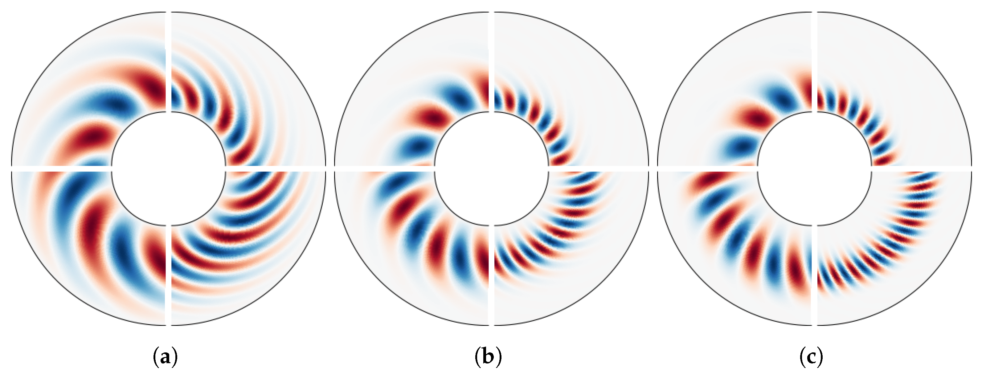
Flow patterns. The form of the convection columns in the equatorial plane is shown in Figure 3. In the differentially heated case (top half of each plot), the modes are adjacent to the inner boundary as the temperature gradient is largest on the tangent circle. This is in contrast with the internally heated case (bottom half of each plot), which will be discussed further in Section 3.1.2. The plots highlight the dependence of the size of the flow structures on both Ekman number (compare left and right of each plot) and Prandtl number (shown in individual plots). In all cases, as the Prandtl number decreases, the convection columns become increasingly radially elongated, accentuating their spiralling structure.
We now look to further the investigations of [10,12] by examining the effect of different heating types and mechanical boundary conditions. Specifically, we aim to investigate how internal heating and stress-free boundary conditions influence the dependence of the critical Rayleigh number on Pr and compare with the differential heated, purely no-slip boundaries case discussed hitherto.

3.1.1. Effect of Mechanical Boundary Conditions

Comparison of critical values (stress-free boundary conditions). Consistent with previous work [19], we find that purely stress-free boundary conditions lead to a larger m c and a larger | ω c | for Pr = 1 , compared with purely no-slip conditions. We now confirm this result across the range of Prandtl numbers tested for both differential heating (Figure 4a) and internal heating (Figure 4b). In other words, for given E, Pr, and heating type (and χ = 0.35 ), we typically find m c NS < m c SF and | ω c | NS < | ω c | SF . In fact, this is also true for the range of χ tested, and we shall return to this in Section 3.2. For differential heating, we reproduce the result found in [19] and confirm that, for Pr = 1 , the critical Rayleigh number satisfies Ra c NS > Ra c SF . However, we note that in the internally heated case it has been observed that Ra c NS < Ra c SF for Pr = 1 [19] and for larger Pr [42]. This raises the question of whether or nor such a situation is possible in the differentially heated case and, if so, how it depends on Pr (and we shall return to this point later).
Comparison of critical values (mixed boundary conditions). We observe that the critical values for the mixed boundary-condition cases are very similar to those of the purely stress-free case (Figure 4a). This similarity arises as the convection columns dominantly interact with the outer boundary at the top and bottom of the column. Although in the differentially heated case the convection columns are found adjacent to the inner boundary, they are not wall-attached modes, and thus the inner boundary plays a weaker role. Consequently, the critical values of a mixed boundary case are closely approximated by the non-mixed boundary condition case with matching outer wall boundary condition (i.e., purely stress-free conditions for our choice of mixed conditions). Deviations in the mixed case (from the purely stress-free case) will depend on the relative strength of the no-slip inner boundary, which, in turn, depends on heating type, Pr, E, and χ .
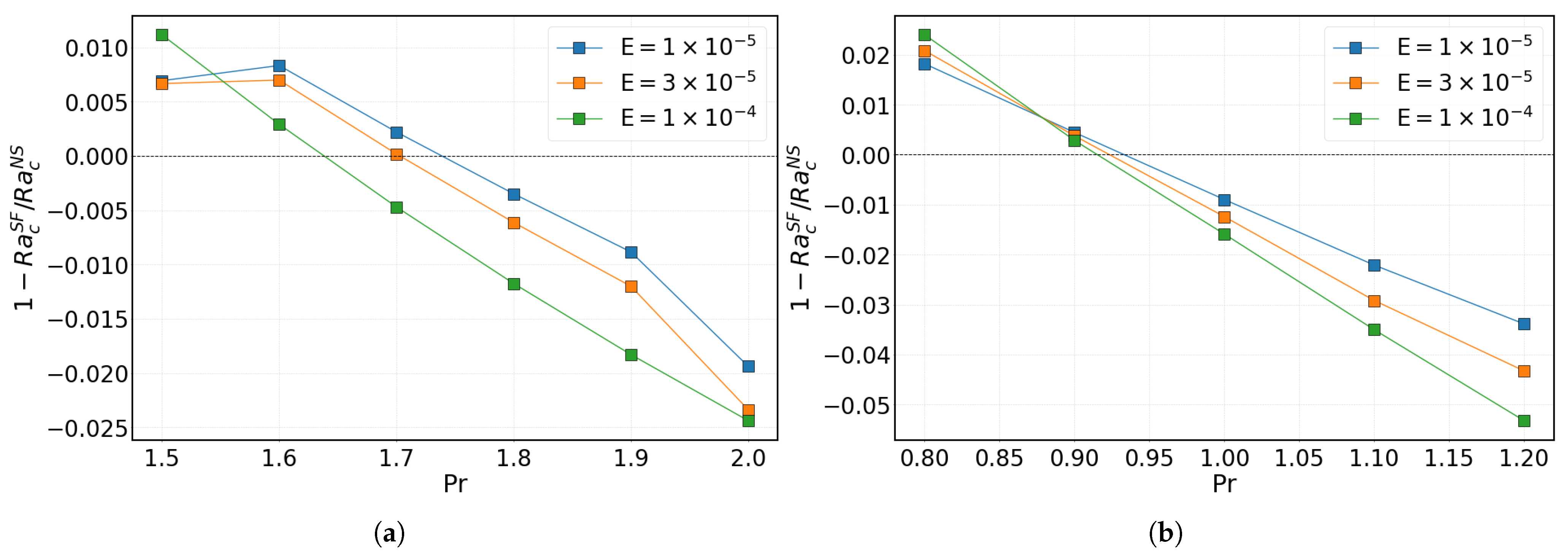
Preference of boundary condition for onset. We now examine, in more detail, how the relationship between Ra c NS and Ra c SF varies with the Prandtl number for differential heating (and will consider the same effect for internal heating in Section 3.1.2). For Pr < 1 , we find that Ra c NS > Ra c SF persists, with the difference between the two values increasing across the explored parameter space (see Figure 4a at small Pr). Hence, for low enough Pr, the Ekman boundary layer restrains the fluid, limiting the growth of instabilities, leading to a larger Ra c . However, increasing the Prandtl number leads to the Ekman boundary layer having a destabilising effect on the flow, thereby reducing Ra c (see Figure 4a at large Pr). This effect occurs for the range of values of Ekman number tested, provided Pr 1.7 . However, the precise transitional point in Pr-space depends slightly on the Ekman number (Figure 5a). We find that for larger values of E, the boundary layer remains sufficiently stabilising at increased Pr, meaning Ra c NS > Ra c SF holds for larger values of Pr. This transition does not affect the critical azimuthal wavenumber, m c , or the critical frequency, ω c , as discussed earlier. We can also highlight the decreasing influence of the Ekman boundary layer at lower Ekman number (since its thickness scales as E 1 / 2 [43]). From Figure 5, we see that as E 0 , Ra c NS / Ra c SF 1 , m c NS / m c SF 1 , and ω c NS / ω c SF 1 . This can be most readily observed in Figure 5b, where smaller values of E tend closer to the value of 1 Ra c SF / Ra c NS = 0 across Pr-space.
Flow patterns. We find very little discernible difference in the pattern of the convection columns for different sets of boundary conditions. Therefore, we do not display further plots in this section beyond those shown in Figure 3, which are for no-slip boundary conditions. The only key difference in the flow patterns are those which are expected from the critical values: the number of convection columns present in a given plot may be slightly different since m c varies (weakly) with selection of boundary condition.

3.1.2. Effect of Heating Type

Previous studies have investigated the effect of different heating cases on critical values. The work of [19] directly compared purely internal and purely differential for Pr = 1 . Subsequent work has focused on differentially heated systems, mainly within the parameter range of Pr [ 0.01 , 10 ] [10,12], whereas [30] has looked at the internal heating case across a much larger range, Pr [ 10 5 , 10 3 ] . Here, we directly compare internal and differential heating while varying the Prandtl number, comparing how each heating case affects the critical values and interacts with boundary condition effects.
Comparison of critical values. Comparing Figure 4a,b, it is clear that the trends with Pr are very similar for each heating type, although the magnitudes of the critical values can differ significantly. This is the case for all boundary conditions we have investigated and, as with differential heating, the mixed boundary conditions under internal heating provide similar results to the purely stress-free conditions. The critical Rayleigh numbers associated with internal heating are up to an order of magnitude larger than the equivalent in a differentially heated system. Conversely, the magnitudes of the critical frequencies are similar in the two heating cases, albeit slightly larger under internal heating. The dependence of the critical wavenumber on heating type is more complicated. For small Pr, values of m c are similar between the two cases, but for large Pr they become increasingly different as the number of modes increases significantly faster in the internally heated case. We shall return to this point below since it is related to a key difference between the two heating cases that we shall discuss next: the location of the onset of the instability.
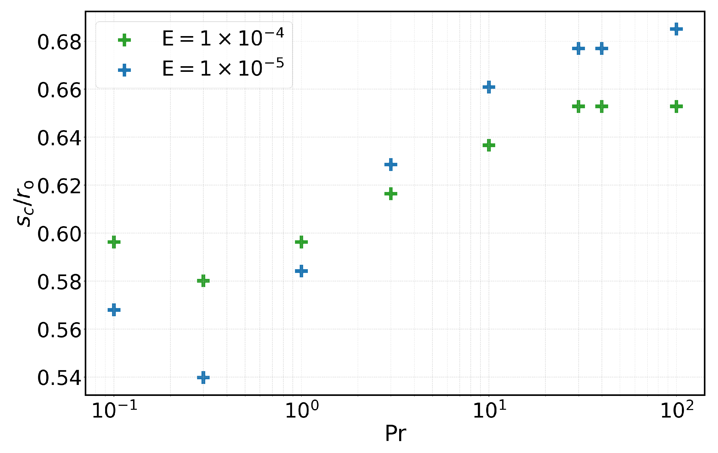
Critical radius. The (relative) resistance to instability in the internal heating case arises due to the outer boundary having the steepest temperature gradient (see Equation (2a)). Therefore, the buoyancy forces are greatest at the outer boundary but must compete with a greater rotational constraint resulting from the increased slope [44]. Equivalently, the Taylor columns are disrupted as, near the outer wall, the fluid is forced to become more z-dependent. As a result, in the internal heating case the instability onsets away from the tangent cylinder at some critical radius, s c , where the competition between buoyancy forces and rotational constraints is most favourable. Conversely, under differential heating, where the inner wall has the steepest temperature gradient, the instability always onsets adjacent to the tangent cylinder. This property is directly observed by comparing the upper half (for differential heating) and lower half (for internal heating) of the individual plots of Figure 3. A natural question is how the critical radius varies with the control parameters of the system. The asymptotic value of the ‘global theory’ of [19] in the case of Pr = 1 was found to be s M / r o 0.5915 , where it was also speculated (but not explored) that s c is dependent on the Prandtl number. In Figure 3 (bottom half of each plot), it is notable that as Pr is increased, the critical radius, s c , becomes (marginally) further from the tangent circle, r i . Figure 6 demonstrates this behaviour over the full parameter range of Pr tested, where we find 0.54 < s c / r o < 0.69 for the cases tested. There are several noteworthy trends to be highlighted. First, broadly speaking, increasing Pr leads to the instability migrating further from the inner boundary. This is likely a result of the weakening effect of the Ekman boundary layer at larger Pr, allowing buoyancy forces to prevail over rotational constraints at a slightly larger s c . Onset at a larger radius also leads to a larger number of modes since the circumference of the circle defined by r = s c / r o increases; this explains why m c increases more rapidly with Pr in the internally heated case, as mentioned earlier. Second, bucking the general trend seen in Figure 6, for small enough Pr, the critical radius begins to increase. Hence, there exists a minimum value of s c as a function of Pr, and we find that this occurs when Pr 0.3 . Third, the dependence on E demonstrates that larger rotation rates amplify the trends seen at both small and large Pr. This is likely because, as rotation is increased, modes become smaller and more localised to their inner/outer edge for small/large Pr (Figure 3).
Preference of boundary condition for onset. The behaviour described above persists across all boundary conditions, and similar trends in Pr are observed in the internally heated case as were found for the differentially heated case (see Figure 5b). A notable difference, however, is the shift in transition where the no-slip case onsets at a lower Ra c . In agreement with previous work [42], we find that, for internal heating, this transition occurs near Pr 1 (Figure 5b), whereas for differential heating the equivalent value was Pr 1.7 (Figure 5a). As with the differential heating case, we have found additional results in this region to more accurately determine where this transition occurs as a function of Pr (and E).
Flow patterns. We have discussed some key effects of the choice of heating type on the form of the convection columns. Aside from the radial location of the instability and the change in the number of azimuthal modes, there is one further observation to be made from Figure 3. The convection cells are more radially elongated in the internally heated case, presumably because their extent is not inhibited by the inner boundary.

3.2. Dependence on Radius Ratio

All results presented in this subsection are for a fixed Prandtl number of Pr = 1, since this allows for straightforward comparison with previous work. As previous work shows [19,31,34], varying χ has an effect on the critical values for the onset of convection. In the sections that follow, we present results for χ { 0.2 , 0.25 , , 0.75 , 0.8 } for a variety of boundary conditions and heating types. However, we begin with a brief discussion of the case with no-slip boundary conditions and differential heating since this allows us to readily verify our results against previous studies.
Critical values.Figure 7 presents critical parameter values as a function of radius ratio found as part of this study. As expected, based on the known scaling laws, all three critical parameters increase with E for all values of χ . Figure 7a shows a small increase in the critical Rayleigh number until χ 0.4 (though this value is weakly dependent on E), where it then starts to decrease. This suggests that a spherical shell with a moderate aspect ratio ( χ 0.4 ) is least favourable to the onset of convection. However, the trend seen in Ra c with χ is highly dependent on the definition of the Rayleigh number used for analysis (as alluded to in Section 2.3). We discuss this point further in Section 3.3. Figure 7b shows that | ω c | peaks at χ 0.55 . Given the instability onsets at s r i (for differential heating), this suggests there is a favourable location in s-space for maximising the drift of the convection columns. Figure 7c shows that the critical wavenumber increases with increasing χ . This is partly due to the fact that, for differential heating, convection onsets in the form of columns at the tangent cylinder to the inner core, and as this inner core gets larger, the convection columns either need to stretch around it or split up into more columns, with the latter being most efficient.
Scaling laws. To plot the curves of best-fit for varying χ , we again make use of scaling laws found in [7], which, for fixed E and Pr, provide:
C i = a i tan arcsin 1 + χ 2 b i 1 + χ 1 χ c i ,
where C 1 = χ 1 Ra c , C 2 = m c , and C 3 = ω c . The fitting parameters a i , b i , and c i for Figure 7 are given in Table 3. Note, there are similarities between the expression for C 1 in (11) and the relationship given by Equation (9) in [34], especially in the form of the part with the c 1 exponent. However, we find a more suitable fit for critical values when using the above scaling law. This may arise due to differences in the range of χ values studied. We keep to intermediate values of χ where the law from [7] (based on the local annulus model for convection outside the tangent cylinder) is appropriate. On the other hand, ref. [34] also test extreme values of χ appropriate to the thickest and thinnest shell cases where the changes in Ra c are more dramatic and require special treatment by their revised scaling law. We do not find each fitted parameter, a i , b i , and c i , tending towards the proposed values provided by [7]; however, we should not necessarily expect to find agreement since those values are derived for internal heating and are specifically finding the scaling for small Ekman numbers. Conversely, here, we use differential heating and retain finite, moderate values of E. Lower values of the Ekman number and more extreme values of χ would be needed to further explore these scaling laws. Nevertheless, for each fixed value of χ , we do recover the expected scalings, Ra c E 4 / 3 , m c E 1 / 3 and ω c E 2 / 3 , as E 0 .
Comparison with previous studies.Figure 7 also shows that, as was the case when varying Pr, the critical values we have calculated as a function of χ agree very well with previous studies (after suitable conversions; see Section 2.3). Both Ra c and | ω c | show excellent agreement with the results of [31,34], and the discrete parameter, m c , is mostly in agreement, especially with the more recent study [31].
Flow patterns. The equatorial sections displayed in Figure 8 show the form of the convection columns. In the differentially heated case (top half of each plot), the modes are adjacent to the inner boundary; comparison with the internally heated case will be made in Section 3.2.2. The plots highlight the dependence of the size of the flow structures on both Ekman number (compare left and right of each plot) and radius radio (shown in individual plots). As χ is increased, the number of columns increases (even if E and Pr are held constant), with our most extreme case (right part of Figure 8d) showing extremely small structures. This highlights the requirement for azimuthal spatial high resolution in nonlinear rotating convection and dynamo simulations.

3.2.1. Effect of Mechanical Boundary Conditions

Comparison of critical values (stress-free boundary conditions).Figure 9 compares the effect of various mechanical boundary conditions on the onset of convection, as a function of radius ratio. Figure 9a shows that purely stress-free boundary conditions cause Ra c to decrease slightly, relative to the purely no-slip case. Hence, with differential heating and for each χ , convective onset is always easiest with stress-free conditions (at least for Pr = 1). This suggests that when using no-slip boundary conditions, the Ekman boundary layers have a stabilising effect on the fluid. This is in contrast to convective onset as a function of Pr, where the preference of boundary conditions varies (see Section 3.1.1). The critical wavenumber (Figure 9a) is altered slightly by the change in boundary conditions, with no-slip boundaries favouring a smaller number of modes (as seen earlier and in previous work). This remains the case across all values of χ , for differential heating, although the difference becomes wider at large χ . For stress-free boundary conditions, the magnitude of the critical frequency is larger than for no-slip boundary conditions (Figure 9a). This is because the boundary layers that arise under no-slip boundary conditions inhibit the flow, causing a lower magnitude frequency. In summary, for given E, χ , and heating type (and Pr = 1) we always find m c NS < m c SF and | ω c | NS < | ω c | SF . Given the results of Section 3.1, it is likely that this remains the case across the full range of Pr and χ (i.e., for those combinations of Pr, χ is not included in our study). Similarly, for differential heating, for given E, χ (and Pr = 1), we always find Ra c SF <   Ra c NS .
Comparison of critical values (mixed boundary conditions).Figure 9 shows that the critical values for the case of mixed boundary conditions are very similar to the purely stress-free set-up. For a fixed choice of χ , the value of Ra c sits between the two other values, and the critical wavenumber and frequency are each almost identical to their equivalent values in the purely stress-free case. Thus, the condition on the outer boundary, where the instability has its primary contact with the boundaries, is predominantly controlling the properties of the instability. Hence, the introduction of a no-slip inner boundary has a minimal effect to the result of the purely stress-free case. This was also observed in Section 3.1 but is now confirmed here for a range of χ . As χ is increased, the three values of Ra c (found under the three different choices of boundary conditions with differential heating) each tend towards the same value, indicating the diminishing role of the boundary conditions at large χ .
Flow patterns. We do not display further plots of the flow structures in this section beyond those shown in Figure 8, which are for no-slip boundary conditions. This is because, as was the case in Section 3.1, the only observable difference in the flow patterns between cases with different boundary conditions is the number of columns, as expected because m c varies (weakly) with selection of boundary condition.

3.2.2. Effect of Heating Type

We now consider the case of internal heating, whilst also retaining the option to vary the boundary conditions. This section complements the numerical study contained in [19], which considered two specific values of χ when comparing differential and internal heating.
Comparison of critical values.Figure 9b shows the critical Rayleigh number decreasing monotonically as χ is increased. This differs from the differentially heated case where the system had a peak in Ra c at χ 0.4 . The trend in the internally heated case suggests that increasing χ always aids the onset of convection. The general trend in critical wavenumber (Figure 9b) is unchanged from the differentially heated case, retaining the significant increase in m c as χ increases. Noteworthy, however, is the slight ‘kink’ in the values at χ 0.4 , which can be attributed to the instability becoming detached from the inner boundary as χ is reduced. We shall return to this point below. This ‘kink’ can also be observed in the plot for the critical frequency (especially for lower E) and, unlike the differentially heated case, there is no peak in | ω c | at χ 0.55 .
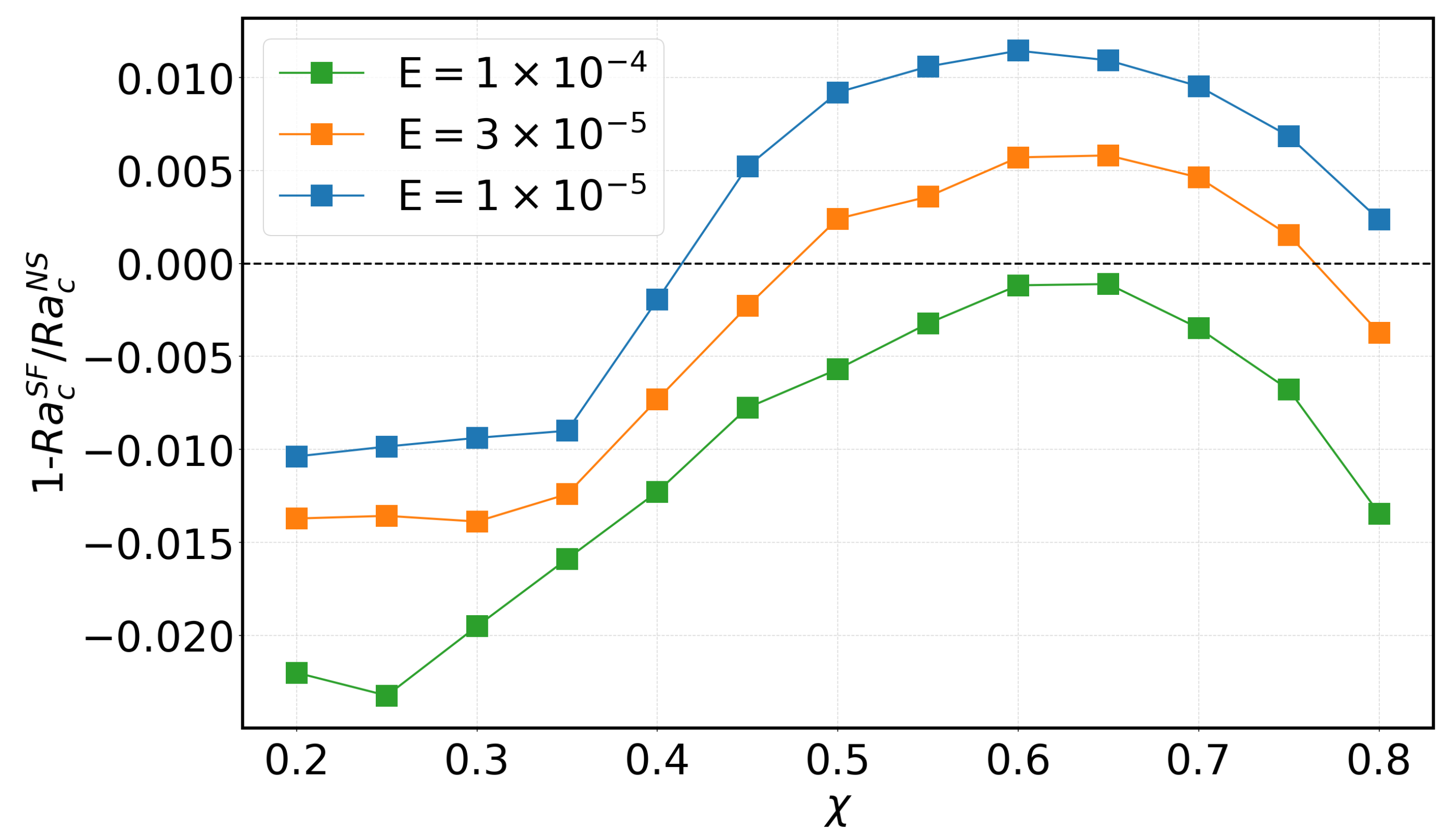
Preference of boundary condition for onset. For the internally heated system, the critical wavenumber and critical frequency are larger under purely stress-free or mixed boundary conditions compared to purely no-slip conditions. This is for the same reasons outlined previously in the case of differential heating. On the other hand, as also found in the case of varying Pr (see Section 3.1), there can be a transition in χ -space where the preferred boundary condition to enable convection is reversed. In other words, the quantity 1 Ra c SF / Ra c NS may change sign as χ is varied, as shown in Figure 10. Note, however, that as a function of χ , this transition only occurs under internal heating. For differential heating we always find Ra c SF <   Ra c NS . The trend of 1 Ra c SF / Ra c NS in χ seen in Figure 10 is similar for all values of E tested. However, this masks a subtlety since the number of times the quantity crosses zero is highly dependent on the Ekman number. For small values of χ , no-slip boundary conditions give a lower critical Rayleigh number for all E. Then, for a sufficiently low value of E (≤3 × 10 5 ), there is a range of χ where stress-free boundary conditions become preferred. At large χ , for E = 3 × 10 5 only, the sign changes again so that no-slip boundary conditions are once again preferred. Note that for a wider range of values of radius ratio than studied here (i.e., for χ > 0.8 ), the final observation at large χ may also be true for lower values of E. The complex behaviour shown in Figure 10 is likely also dependent on Pr and, as such, may warrant further study as a function of both E and Pr. Nevertheless, the trend we can draw out from Figure 10 is that, at the low values of E relevant to planetary interiors, it is likely that no-slip (stress-free) boundaries are preferred at small (large) enough χ .
Location of convection. As noted earlier, when using internal heating, it is possible for convection to onset away from the tangent cylinder. Owing to the strengthening of the temperature gradient with radius, the instability manifests at a critical cylinder of radius, s M 0.5915 r o , provided χ is small enough. The value of s M was asymptotically derived as part of a ‘global theory’ [18,19]. The critical cylinder matches that of the full sphere (where the differentially heated case cannot arise), since this position is unaffected when a sufficiently small inner core is introduced. From Figure 8a (lower half for internal heating), it is immediately apparent, in the case of χ = 0.2 < s M / r o , that the convection columns congregate at a radial value away from the inner core, as predicted. As χ is increased, the effect remains but becomes less obvious at χ = 0.45 (Figure 8b). Naturally, as the inner core increases in size, it eventually encroaches on the columns found within the critical cylinder. Thus, for large enough χ , and certainly for χ > s M / r o , the optimal location for convection to manifest is at some critical radius, s L , adjacent to the tangent cylinder (mirroring the situation for differential heating) [19]. The value of s L was found in the earlier ‘local theory’ [14,15,44]. In Figure 8c,d (where χ > s M / r o ), the two heating cases appear indistinguishable since columns form adjacent to the tangent cylinder regardless.
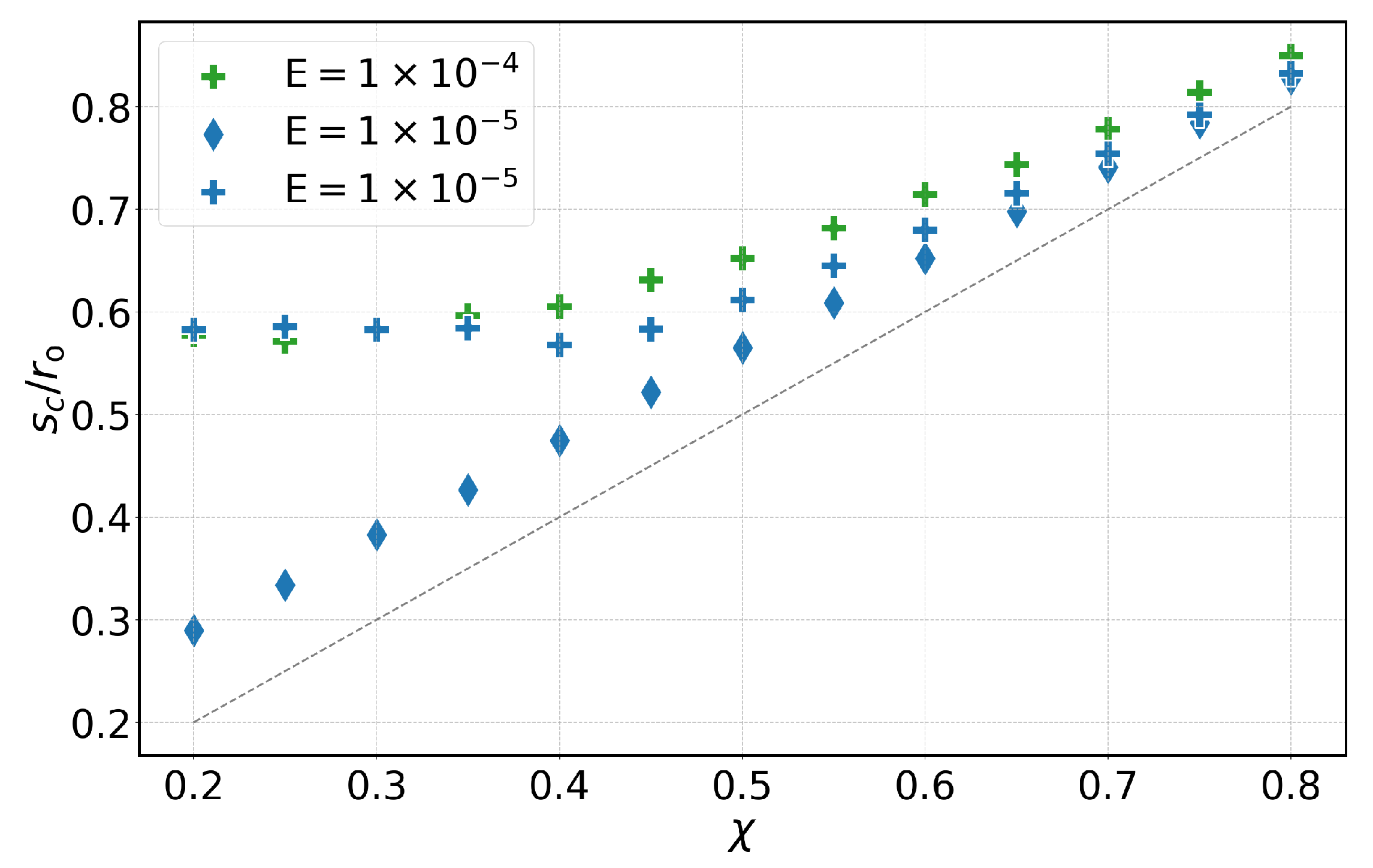
Critical radius. In our work, the critical radius was discussed in Section 3.1.2 for the fixed radius ratio of χ = 0.35 . We now focus on the dependence of the critical radius with χ . Previous work [19] studied only two values of χ and confirmed that s c s M for χ = 0.35 and s c s L for χ = 0.65 . We track the critical radius across a range of values of χ for both internal heating and (the more trivial) differential heating, as shown in Figure 11. For the differentially heated system, the critical radius closely follows the curve s / r o = χ , as expected. Also notable is that, as χ increases, the critical cylinder moves closer to the tangent cylinder. This is a result of the columns reduction in radial (and azimuthal) extent as χ is increased (as seen clearly in Figure 8), allowing a closer proximity between the centre of the cells and the inner boundary. For the internally heated system, two different behaviours can be observed, as expected. For small χ , the critical radius satisfies s c s M 0.59 r o for both values of E shown. For large χ , we instead find that the critical radius moves outwards linearly with χ . It is notable that the behaviour of the two heating types is different, even for s > s M . Columns reside farther from the inner boundary in the internally heated case and the location of the critical cylinder in the two heating cases does not coincide (except perhaps at very large χ ). The smaller extent of the columns at low Ekman number also draws the columns closer to the tangent cylinder. Lastly, the transition from s c s M to s c s L in the interval 0.4634 < s / r o < 0.5004 (where neither the ‘global’ nor the ‘local’ theory applies [19]) appears to be smooth.

3.3. Dependence on Nondimensionalisation

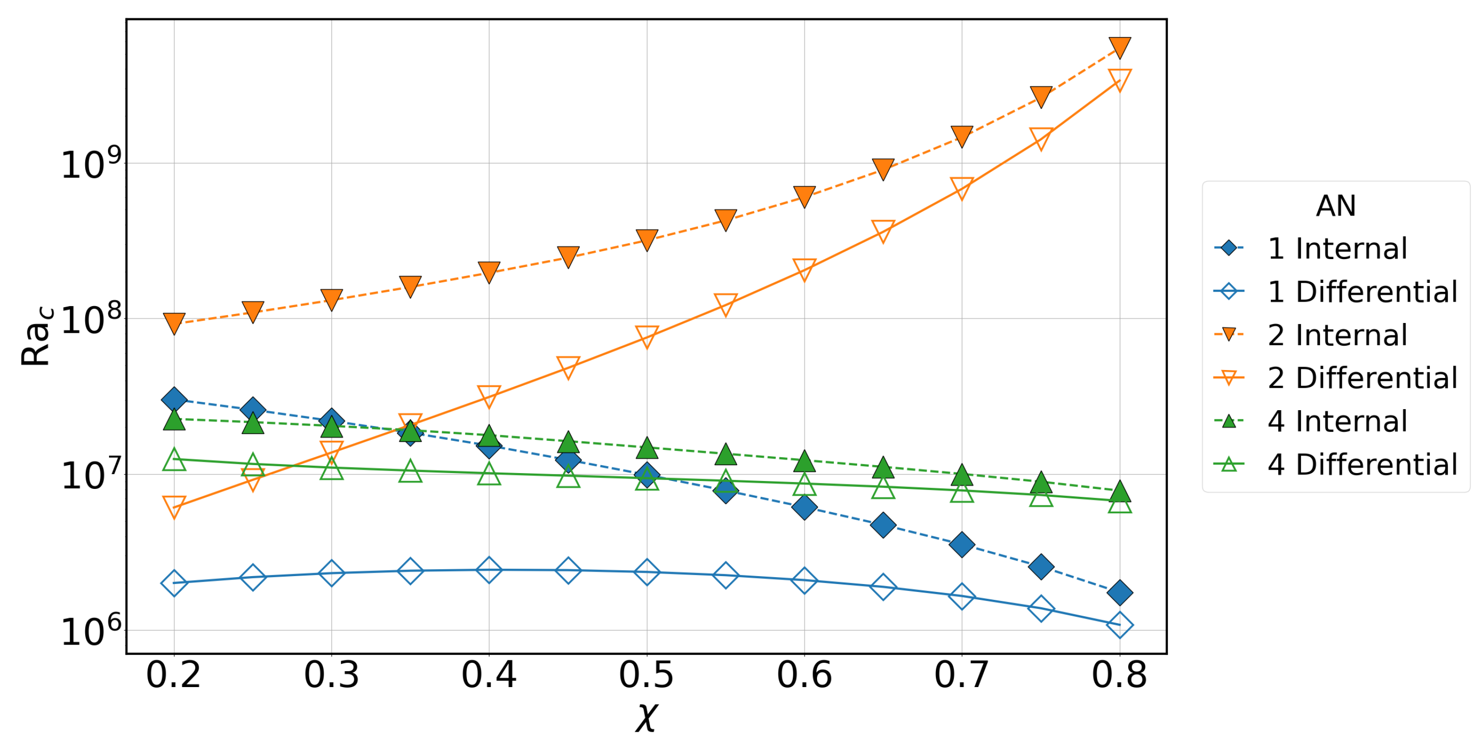
As previously discussed, we confirmed the veracity of our results against previous studies [19,31,34] using conversions given in Section 2.3, with selected points shown in Figure 2 and Figure 7. As shown in Table 1, conversion of Ra c between alternative non-dimensionalisations requires different factors involving χ . Hence, beyond simply confirming our results, it is also natural to convert our raw critical Rayleigh numbers to their equivalent values in the alternative nondimensionalisations and compare the trend in Ra c with χ in each. Figure 12 shows the dependence of Ra c on radius ratio for each of the nondimensionalisations.
Comparison with AN-4. First, we re-emphasise that, for AN-1 (as used in our study) and under differential heating, Ra c decreases as χ increases but only after a shallow peak is reached at χ 0.4 . Conversely, Ra c is a monotonically decreasing function of χ under internal heating. The general trend of Ra c decreasing with χ is also maintained for both heating cases for AN-4 (used by [31,34]). The notable difference between the trends of AN-1 and AN-4 is the steepness of the curves for internal heating. AN-1 uses the temperature gradient (evaluated at r o ) within the definition of Ra (the key difference with AN-3 and AN-4). Since the temperature gradient under internal heating scales with r, and hence becomes strongest at the outer boundary, Ra c is significantly reduced as the onset location moves towards the outer boundary. This effect is far more modest when the Rayleigh number is measured using the temperature difference because the geometric factor of Γ ( χ ) within the heat equation reduces the effect of buoyancy, leading to larger values of Ra c . Note that values of Ra c for nondimensionalisation AN-3 very closely follow those of AN-4. Based on the trends in Ra c with χ shown by AN-1, AN-3, and AN-4, a case can be made for thinner shells aiding the onset of convection. Indeed, ref. [34] argue the effect is explained by the result that convection is easiest in cylinders of large aspect ratio [45], owing to the reduced size of the boundary layers within the total volume of the fluid. Boundary layer thickness scales as E 1 / 2 so, at fixed Ekman number, the argument is predicated on the volume of the fluid region increasing, as it does when d is used as the nondimensional lengthscale.
Comparison with AN-2. A stark feature of Figure 12 is seen in the values for AN-2 (used by [19]), where the trend of Ra c with χ reverses compared to the other alternative nondimensionalisations discussed. For both heating types the value of Ra c increases by over a magnitude as the fluid shell becomes thinner. The key difference of AN-2 is the choice of lengthscale (now the outer radius of the sphere). Since r o is arguably the more appropriate measure for studies focussed on systems with a fixed outer dimension (see discussion in the ‘Further Remarks’ of Section 2.3), the interpretation from Figure 12 is that convection is inhibited as the inner core grows. For thinner shells, the slope of the outer boundary at which the convection columns manifest is steeper, requiring more z-dependent motion near the boundaries. Since, with r o as the nondimensional lengthscale, the total fluid volume decreases as χ increases, the boundary layers (which have fixed thickness at a given E) also have an enhanced role. This effect is therefore opposite to that described above for AN-2. Hence, a larger level of driving from buoyancy (i.e., larger Ra) is needed to overcome the combined effects of the Taylor–Proudman constraint and enhanced influence of the boundary layers at large χ . The slope at small χ in the internally heated case is less steep since the presence of the inner core has a more limited effect until the inner boundary approaches the critical cylinder where the instability is found.
The above demonstrates that the choice of nondimensionalisation is clearly important when interpreting results and comparing the models of different physical systems.

4. Discussion

In this section, we address the questions posed in Section 1 in turn and offer further discussion of our findings.
Preference of boundary conditions. The transition point in parameter space where the boundary condition that offers the lowest Ra c changes is found to be dependent on Pr, χ , E, and heating type. This describes the point at which the Ekman boundary layer begins to have a destabilising effect. When varying Pr, no-slip boundary conditions give a lower Ra c for either Pr 1.7 (differential heating case) or Pr 0.9 (internal heating case). When varying χ , the point of transition only occurs under the internally heated case, and the behaviour depends on the Ekman number in a non-trivial fashion. At E = 3 × 10 5 , the range where no-slip boundary conditions give a higher Ra c is 0.47 χ 0.76 and hence, in this range (and with Pr = 1 ), the Ekman boundary layer is stabilising. However, for a higher Ekman number, E = 10 4 , there is no range of χ where this is the case, and for a lower Ekman number, E = 10 5 , this range of χ increases. For the strongly rotating physical systems motivated by this work, our results suggest that no-slip boundary conditions could be preferred if the shell is thick enough and driven solely by volumetric heat sources (or possibly a combination of internal and differential heating, which is beyond the scope of the current study). However, the physical systems typically have low values of Pr, for which our results would suggest a preference for stress-free boundaries. In our work, we have fixed one of either Pr or χ whilst varying the other. Therefore, further exploration of the parameter space would be needed to determine which boundary condition is more likely to aid convective onset in planetary interiors.
Mixed boundary condition behaviour. Under our mixed boundary conditions (with a no-slip inner boundary and a stress-free outer boundary), we found that the influence of the outer boundary dominates. Consequently, the critical values of this mixed case are well approximated by the purely stress-free case. This holds when varying either Pr or χ . In either case, slight variations are found in Ra c , m c and ω c depending on the effect of the no-slip inner boundary for the heating type, and point in parameter space. This result suggests that physical systems approximated in mathematical models using a mixed set of conditions (e.g., the Sun’s convection zone) could also be approximated using purely stress-free conditions, at least near the onset of convection.
Location of convective onset. In the case of differential heating, the critical cylinder (at s = s c ) at which the instability onsets is found close to the tangent cylinder (i.e., s c s L , as predicted by local theory [14,15,44]) for all values of χ and Pr tested. With internal heating, as Pr is varied, the critical cylinder varies in the range 0.54 s c / r o 0.69 , a significant departure from the asymptotically predicted value of s M 0.59 r o for the Pr = 1 case [19]. Furthermore, the departure from s M is largest for smaller Ekman numbers with low Pr and low E favouring s c < s M . This result suggests that at Ekman and Prandtl numbers applicable to planetary interiors the convection will onset closer to the inner boundary than predicted for Pr = 1 (assuming convection is at least partly driven by volumetric heat sources and χ < s c ). Determining the location more precisely requires further investigations at Ekman numbers lower than those studied in our work. When fixing Pr = 1 , the expected results of s c s M for χ 0.4 and s c s L , for χ 0.5 , were recovered. For the parameter values tested in our work, s c appears to undergo a smooth transition from s M to s L (as χ is increased in the interval 0.4 < χ < 0.5 ). Further results within this interval (including at alternative values of E and Pr) would be required to confirm the behaviour.
Remarks on nondimsionalisation. A comparison of nondimensionalisations showed that the trend in critical Rayleigh number is dependent on the nondimensional lengthscale chosen. In particular, for a Rayleigh number defined with a fixed outer boundary location (so the total volume of the spherical system is fixed), the onset of convection is inhibited in thinner shells. Conversely, if the volume of the entire system is allowed to vary (by choosing the gap width in the definition of Ra), the larger fluid volume (present even in thinner shells) compensates through additional geometric factors. Since the former set-up is appropriate for a chosen planet with a growing inner core, future studies focussing on such behaviour could consider using r o for nondimensionalisation. This choice has the additional benefit of governing equations that are independent of geometric factors involving χ (see Equation (6a)–(6d)), with the effect of the aspect ratio appearing through the moving location inner boundary condition with χ . For studies using fixed χ each nondimensional lengthscale can be regarded as equally informative.
Further studies. Additional studies could complement this research. Examining how the radius ratio affects the critical values at different Pr would help build a more complete understanding of the full parameter space. Investigations into higher and lower values of Pr and χ would reveal the effects of different boundary conditions as Pr 0 and χ 0 or as Pr and χ 1 . Further work could also clarify our understanding of the transition point where 1 Ra c SF / Ra c NS changes sign and, in particular, the dependence on Ekman number. Implementing an alternative mixed boundary condition (of a no-slip outer boundary with a stress-free inner boundary) could also verify that the effect of the outer boundary condition dominates the onset of convection, leading to similar critical values to those of a purely no-slip case. Additionally, a mixture of differential and internal heating types could be explored to determine whether or not the critical values will resemble those of internal or differential heating, analogous to the mixed boundary conditions. The extensive number of critical values across a wide parameter space will serve not only as a basis for further convection studies but also as a valuable resource for simulations of convection-driven dynamos.

Author Contributions

Conceptualisation, W.S., F.C., R.D.S. and R.J.T.; methodology, W.S., F.C., R.D.S. and R.J.T.; software, R.J.T.; validation, W.S., F.C. and R.J.T.; formal analysis, W.S. and F.C.; investigation, W.S. and F.C.; data curation, W.S. and F.C.; writing—original draft preparation, W.S., F.C. and R.J.T.; writing—review and editing, R.D.S. and R.J.T.; visualisation, W.S. and F.C.; supervision, R.D.S. and R.J.T.; project administration, R.J.T.; funding acquisition, R.D.S. and R.J.T. All authors have read and agreed to the published version of the manuscript.

Funding

F.C. is grateful for an EPSRC PhD scholarship (EP/W524359/1). The work of R.D.S. and R.J.T. was supported by the UK Science and Technology Facilities Council (grant numbers ST/Y001672/1 and ST/Y00146X/1).

Data Availability Statement

The original data presented in the study are openly available [46].

Conflicts of Interest

The authors declare no conflicts of interest.

Appendix A

In this appendix, we further detail our numerical methods including the chosen form for u , the discretisation of the problem, and the form of the matrices A and M discussed in Section 2. In the following, we adhere closely to the method and choices of [37].

Appendix A.1. Poloidal–Toroidal Decomposition

The velocity field is decomposed into poloidal and toroidal parts using scalars P and T , such that
u = × × ( r P r ^ ) + × ( r T r ^ ) .
This is the most general decomposition that automatically satisfies the solenoidal condition on u , Equation (3c). Taking the r-components of the curl and the double curl of Equation (3a) yields equations for P and T , given by
E t 2 L 2 2 P 2 φ 2 P 2 Q T + ERa L 2 Θ = 0 ,
E t 2 L 2 T 2 T φ + 2 Q P = 0 ,
Pr Θ t = r 1 Λ ( 1 χ ) Λ ( r ) L 2 P + 2 Θ .
In terms of the poloidal and toroidal scalars, the impermeable, fixed temperature boundary conditions at the inner, r = r i , and outer, r = r o , boundaries become
P = 0
Θ = 0 ,
and the no-slip and the stress-free boundary conditions become
P r = T = 0 ,
2 P r 2 = r T r = 0 ,
respectively.

Appendix A.2. Expansions in Trial Functions and Discretisation

The following ansatz are then substituted and used for the scalar fields P , T , and Θ :
T = n = 1 N x + 2 l = 0 L T n l r 1 T n ( r ) Y 2 l + m + 1 m ( θ , φ ) e σ t ,
P = n = 1 N x + 4 l = 0 L P n l r 1 T n ( r ) Y 2 l + m m ( θ , φ ) e σ t ,
Θ = n = 1 N x + 2 l = 0 L Θ n l T n ( r ) Y 2 l + m m ( θ , φ ) e σ t .
Here, the T n ( r ) represents the n-th Chebyshev polynomial in the radial coordinate and Y l ˜ m ( θ , φ ) is a Schmidt-normalised spherical harmonic [47]. For each ansatz in (A4), the degree l ˜ is chosen to implement the Busse symmetry [15,48] found at convective onset. N x and L give the radial and angular resolutions, respectively, while any additional terms appearing in the radial summation account for the imposed boundary conditions on that scalar field.

Appendix A.3. Projection onto the Trial Functions and Matrix Expressions

By substituting the forms given by Equation (A4a)–(A4c) into Equations (A2a)–(A2c) and (A3a)–(A3d), the matrices A and M that form the eigenvalue problem of Equation (5) can be constructed. The time dependence will enter through the eigenvalue, σ , and so all terms with a factor of σ are entered into M . The remaining terms make up the A matrix. With these equations, we can outline the explicit forms of Equations (A2a)–(A2c) and (A3a)–(A3d) in terms of the Fourier coefficients P n l , T n l , and Θ n l . Note that, in what follows, we use the notation T n ( i ) ( r ) = d i T n d r i ( r ) .
Starting with the poloidal equation, Equation (A2a), we obtain:
σ E n = 1 N x + 4 l = 0 L P n l λ 0 ( λ 0 + 1 ) T n ( 2 ) λ 0 ( λ 0 + 1 ) r 2 T n = E n = 1 N x + 4 l = 0 L P n l λ 0 ( λ 0 + 1 ) [ T n ( 4 ) 2 λ 0 ( λ 0 + 1 ) r 2 T n ( 2 ) + 4 λ 0 ( λ 0 + 1 ) r 3 T n ( 1 ) + λ 0 ( λ 0 + 1 ) ( λ 0 ( λ 0 + 1 ) 6 ) r 4 T n ] + 2 i m n = 1 N x + 4 l = 0 L P n l T n ( 2 ) λ 0 ( λ 0 + 1 ) r 2 T n 2 n = 1 N x + 2 l = 0 L T n l λ 0 ( λ 0 + 2 ) 2 λ 0 + 3 ( λ 0 + 1 ) 2 m 2 T n ( 1 ) + ( λ 0 + 1 ) r 1 T n 2 n = 1 N x + 2 l = 1 L + 1 T n l λ 0 2 1 2 λ 0 1 λ 0 2 m 2 T n ( 1 ) λ 0 r 1 T n ERa n = 1 N x + 2 l = 0 L Θ n l λ 0 ( λ 0 + 1 ) r T n ,
where λ 0 = 2 l + m . The toroidal equation, Equation (A2b), has a similar form:
σ E n = 1 N x + 2 l = 0 L T n l λ 1 ( λ 1 + 1 ) T n = 2 i m n = 1 N x + 2 l = 0 L T n l T n + E n = 1 N x + 2 l = 0 L T n l λ 1 ( λ 1 + 1 ) T n ( 2 ) λ 1 ( λ 1 + 1 ) r 2 T n + 2 n = 1 N x + 4 l = 1 L 1 P n l λ 1 ( λ 1 + 2 ) 2 λ 1 + 3 ( λ 1 + 1 ) 2 m 2 T n ( 1 ) + ( λ 1 + 1 ) r 1 T n + 2 n = 1 N x + 4 l = 0 L P n l λ 1 2 1 2 λ 1 1 λ 1 2 m 2 T n ( 1 ) λ 1 r 1 T n ,
where λ 1 = 2 l + m + 1 . Lastly, the heat equation, Equation (A2c), gives:
σ Pr n = 1 N x + 2 l = 0 L Θ n l T n = n = 1 N x + 4 l = 0 L P n l λ 0 ( λ 0 + 1 ) r 2 λ 0 ( 1 χ ) λ 0 ( r ) T n + n = 1 N x + 2 l = 0 L Θ n l T n ( 2 ) + 2 r 1 T n ( 1 ) λ 0 ( λ 0 + 1 ) r 2 T n ,
where, again, λ 0 = 2 l + m .
The boundary value problem is completed by the boundary conditions found in Equation (A3a)–(A3d). Applying the ansatz to these conditions, we obtain the following form for each type of conditions. The impermeable boundary condition leads to
0 = n = 1 N x + 4 l = 0 L P n l T n ( r ) ,
while the fixed temperature boundary imposes
0 = n = 1 N x + 2 l = 0 L Θ n l T n ( r ) .
The no-slip conditions become
0 = n = 1 N x + 4 l = 0 L P n l T n ( 1 ) ( r ) and 0 = n = 1 N x + 2 l = 0 L T n l T n ( r ) ,
while the stress-free conditions become
0 = n = 1 N x + 4 l = 0 L P n l r T n ( 2 ) ( r ) 2 T n ( 1 ) ( r ) and 0 = n = 1 N x + 2 l = 0 L T n l r T n ( 1 ) 2 T n .
Finally, the eigenvector v appearing in Equation (5) is composed of the coefficients P n l , T n l , and Θ n l . For an eigenvector with definition N x and L, it is structured as follows:
v = [ P 10 P ( N x + 4 ) 0 T 10 T ( N x + 2 ) 0 Θ 10 Θ ( N x + 2 ) 0 P 1 L P ( N x + 4 ) L T 1 L T ( N x + 2 ) L Θ 1 L Θ ( N x + 2 ) L ] T ,
and has length ( 3 ( N x + 2 ) + 2 ) ( L + 1 ) to account for each value of n and l. Once v and, by extension, P n l , T n l , and Θ n l are determined, the temperature field can be constructed via Equation (A4c), and the velocity field is determined from Equations (A1), (A4a), and (A4b).

Appendix B

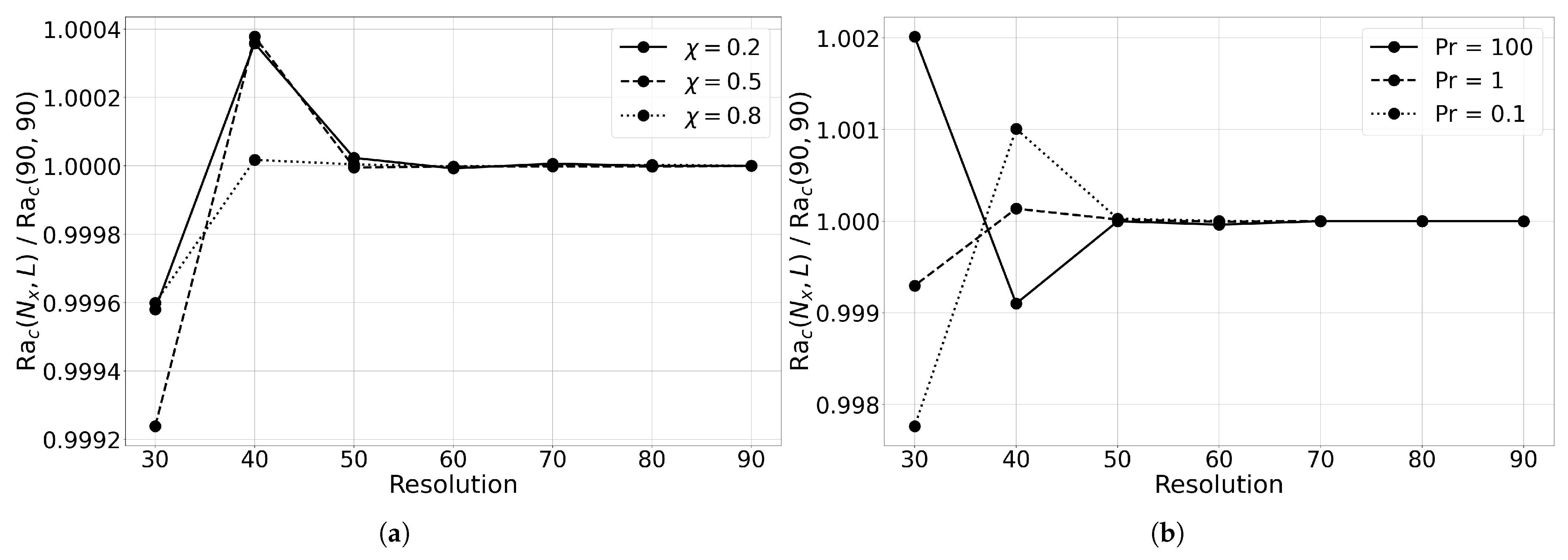
In this appendix, we detail convergence tests performed to validate our choice of resolution. For E = 10 5 (the most numerically demanding case studied), we consider Ra c ( N x , L ) as a function of the resolution parameters, N x and L, with N x = L . Figure A1 shows that critical Rayleigh numbers have converged to within 0.003 % of Ra c at N x = L = 90 when a resolution of N x = L 50 is used. This is the case for Pr and χ values tested from across the full range of values used in this study.
Figure A1. Dependence of Ra c on resolution for (a) different values of χ with Pr = 1 and (b) different values of Pr with χ = 0.35 . Differential heating and purely no-slip boundary conditions are applied and E = 10 5 . As N x = L , the horizontal axis represents both resolution parameters.
Fluids 10 00237 g0a1

References

  1. Busse, F.H.; Simitev, R.D. Planetary Dynamos. In Treatise on Geophysics; Elsevier: Amsterdam, The Netherlands, 2015; pp. 239–254. [Google Scholar] [CrossRef]
  2. Dormy, E. Rapidly Rotating Magnetohydrodynamics and the Geodynamo. Annu. Rev. Fluid Mech. 2025, 57, 335–362. [Google Scholar] [CrossRef]
  3. Charbonneau, P. Solar Dynamo Theory. Annu. Rev. Astron. Astrophys. 2014, 52, 251–290. [Google Scholar] [CrossRef]
  4. Jones, C.A. Planetary Magnetic Fields and Fluid Dynamos. Annu. Rev. Fluid Mech. 2011, 43, 583–614. [Google Scholar] [CrossRef]
  5. Tikoo, S.M.; Evans, A.J. Dynamos in the Inner Solar System. Annu. Rev. Earth Planet. Sci. 2022, 50, 99–122. [Google Scholar] [CrossRef]
  6. Tilgner, A.; Busse, F.H. Finite-amplitude convection in rotating spherical fluid shells. J. Fluid Mech. 1997, 332, 359–376. [Google Scholar] [CrossRef]
  7. Simitev, R.D.; Busse, F.H. Patterns of convection in rotating spherical shells. New J. Phys. 2003, 5, 97. [Google Scholar] [CrossRef]
  8. Christensen, U.R. Zonal flow driven by strongly supercritical convection in rotating spherical shells. J. Fluid Mech. 2002, 470, 115–133. [Google Scholar] [CrossRef]
  9. King, E.M.; Aurnou, J.M. Turbulent convection in liquid metal with and without rotation. Proc. Natl. Acad. Sci. USA 2013, 110, 6688–6693. [Google Scholar] [CrossRef]
  10. Fan, W.; Wang, Q.; Lin, Y. Scaling behaviour of rotating convection in a spherical shell with different Prandtl numbers. J. Fluid Mech. 2024, 998, A20. [Google Scholar] [CrossRef]
  11. Busse, F.H.; Simitev, R.D. Dynamos driven by convection in rotating spherical shells. Astron. Nachrichten Astron. Notes 2005, 326, 231–240. [Google Scholar] [CrossRef]
  12. Christensen, U.R.; Aubert, J. Scaling properties of convection-driven dynamos in rotating spherical shells and application to planetary magnetic fields. Geophys. J. Int. 2006, 166, 97–114. [Google Scholar] [CrossRef]
  13. Simitev, R.D. Double-diffusive convection in a rotating cylindrical annulus with conical caps. Phys. Earth Planet. Inter. 2011, 186, 183–190. [Google Scholar] [CrossRef]
  14. Roberts, P.H. On the thermal instability of a rotating-fluid sphere containing heat sources. Philos. Trans. R. Soc. London. Ser. A Math. Phys. Sci. 1968, 263, 93–117. [Google Scholar] [CrossRef]
  15. Busse, F.H. Thermal instabilities in rapidly rotating systems. J. Fluid Mech. 1970, 44, 441–460. [Google Scholar] [CrossRef]
  16. Chandrasekhar, S. Hydrodynamic and Hydromagnetic Stability; Clarendon: Oxford, UK, 1961. [Google Scholar]
  17. Soward, A.M. On the Finite amplitude thermal instability of a rapidly rotating fluid sphere. Geophys. Astrophys. Fluid Dyn. 1977, 9, 19–74. [Google Scholar] [CrossRef]
  18. Jones, C.A.; Soward, A.M.; Mussa, A.I. The onset of thermal convection in a rapidly rotating sphere. J. Fluid Mech. 2000, 405, 157–179. [Google Scholar] [CrossRef]
  19. Dormy, E.; Soward, A.M.; Jones, C.A.; Jault, D.; Cardin, P. The onset of thermal convection in rotating spherical shells. J. Fluid Mech. 2004, 501, 43–70. [Google Scholar] [CrossRef]
  20. Zhang, K. On coupling between the Poincaré equation and the heat equation. J. Fluid Mech. 1994, 268, 211–229. [Google Scholar] [CrossRef]
  21. Ardes, M.; Busse, F.; Wicht, J. Thermal convection in rotating spherical shells. Phys. Earth Planet. Inter. 1997, 99, 55–67. [Google Scholar] [CrossRef]
  22. Busse, F.H.; Simitev, R.D. Inertial convection in rotating fluid spheres. J. Fluid Mech. 2004, 498, 23–30. [Google Scholar] [CrossRef]
  23. Zhang, K.; Earnshaw, P.; Liao, X.; Busse, F.H. On inertial waves in a rotating fluid sphere. J. Fluid Mech. 2001, 437, 103–119. [Google Scholar] [CrossRef]
  24. Zhang, K.; Liao, X. A new asymptotic method for the analysis of convection in a rapidly rotating sphere. J. Fluid Mech. 2004, 518, 319–346. [Google Scholar] [CrossRef]
  25. Zhang, K.; Liao, X.; Busse, F.H. Asymptotic solutions of convection in rapidly rotating non-slip spheres. J. Fluid Mech. 2007, 578, 371–380. [Google Scholar] [CrossRef]
  26. Braginsky, S.I.; Roberts, P.H. Equations governing convection in earth’s core and the geodynamo. Geophys. Astrophys. Fluid Dyn. 1995, 79, 1–97. [Google Scholar] [CrossRef]
  27. Soderlund, K.M.; Stanley, S.; Cao, H.; Calkins, M.A.; Browning, M.K. Puzzles in Planetary Dynamos: Implications for Planetary Interiors. Annu. Rev. Earth Planet. Sci. 2025, 53, 305–337. [Google Scholar] [CrossRef]
  28. Miesch, M.S.; Toomre, J. Turbulence, Magnetism, and Shear in Stellar Interiors. Annu. Rev. Fluid Mech. 2009, 41, 317–345. [Google Scholar] [CrossRef]
  29. Garcia, F.; Chambers, F.R.N.; Watts, A.L. Onset of low Prandtl number thermal convection in thin spherical shells. Phys. Rev. Fluids 2018, 3. [Google Scholar] [CrossRef]
  30. Silva, L.; Mather, J.F.; Simitev, R.D. The onset of thermo-compositional convection in rotating spherical shells. Geophys. Astrophys. Fluid Dyn. 2019, 113, 377–404. [Google Scholar] [CrossRef]
  31. Barik, A.; Triana, S.; Calkins, M.; Stanley, S.; Aurnou, J. Onset of convection in rotating spherical shells: Variations with radius ratio. Earth Space Sci. 2023, 10, e2022EA002606. [Google Scholar] [CrossRef]
  32. Morison, A.; Labrosse, S.; Deguen, R.; Alboussière, T. Onset of thermal convection in a solid spherical shell with melting at either or both boundaries. Geophys. J. Int. 2024, 238, 1121–1136. [Google Scholar] [CrossRef]
  33. Busse, F.H.; Simitev, R.D. Parameter dependences of convection-driven dynamos in rotating spherical fluid shells. Geophys. Astrophys. Fluid Dyn. 2006, 100, 341–361. [Google Scholar] [CrossRef][Green Version]
  34. Al-Shamali, F.; Heimpel, M.; Aurnou, J. Varying the spherical shell geometry in rotating thermal convection. Geophys. Astrophys. Fluid Dyn. 2004, 98, 153–169. [Google Scholar] [CrossRef]
  35. Silva, L.; Gupta, P.; MacTaggart, D.; Simitev, R.D. Effects of Shell Thickness on Cross-Helicity Generation in Convection-Driven Spherical Dynamos. Fluids 2020, 5, 245. [Google Scholar] [CrossRef]
  36. Davies, C.; Gubbins, D. A buoyancy profile for the Earth’ s core. Geophys. J. Int. 2011, 187, 549–563. [Google Scholar] [CrossRef]
  37. Jones, C.A.; Kuzanyan, K.M.; Mitchell, R.H. Linear theory of compressible convection in rapidly rotating spherical shells, using the anelastic approximation. J. Fluid Mech. 2009, 634, 291–319. [Google Scholar] [CrossRef]
  38. Gibbons, S.; Gubbins, D.; Zhang, K. Convection in rotating spherical fluid shells with inhomogeneous heat flux at the outer boundary. Geophys. Astrophys. Fluid Dyn. 2007, 101, 347–370. [Google Scholar] [CrossRef]
  39. Teed, R.J.; Dormy, E. Solenoidal force balances in numerical dynamos. J. Fluid Mech. 2023, 964, A26. [Google Scholar] [CrossRef]
  40. Net, M.; Garcia, F.; Sánchez, J. On the onset of low-Prandtl-number convection in rotating spherical shells: Non-slip boundary conditions. J. Fluid Mech. 2008, 601, 317–337. [Google Scholar] [CrossRef]
  41. Zhang, K. Convection in a rapidly rotating spherical shell at infinite Prandtl number: Steadily drifting rolls. Phys. Earth Planet. Inter. 1991, 68, 156–169. [Google Scholar] [CrossRef]
  42. Zhang, K.; Jones, C.A. The influence of Ekman boundary layers on rotating convection. Geophys. Astrophys. Fluid Dyn. 1993, 71, 145–162. [Google Scholar] [CrossRef]
  43. Cushman-Roisin, B.; Beckers, J.M. The ekman layer. In International Geophysics; Elsevier: Amsterdam, The Netherlands, 2011; Volume 101, pp. 239–270. [Google Scholar] [CrossRef]
  44. Busse, F.H.; Cuong, P. Convection in rapidly rotating spherical fluid shells. Geophys. Astrophys. Fluid Dyn. 1977, 8, 17–41. [Google Scholar] [CrossRef]
  45. Zhang, K.; Greed, G. Convection in rotating annulus: An asymptotic theory and numerical solutions. Phys. Fluids 1998, 10, 2396–2404. [Google Scholar] [CrossRef]
  46. Seeley, W.; Coke, F.; Simitev, R.D.; Teed, R.J. Influence of Boundary Conditions and Heating Modes on Convective Onset in Rotating Spherical Shells. 2025. Available online: https://researchdata.gla.ac.uk/id/eprint/2015 (accessed on 1 September 2025).
  47. Blakely, R.J. Spherical Harmonic Analysis. In Potential Theory in Gravity and Magnetic Applications; Cambridge University Press: Cambridge, UK, 1995; pp. 100–127. [Google Scholar] [CrossRef]
  48. Busse, F.H.; Riahi, N. Patterns of convection in spherical shells. Part 2. J. Fluid Mech. 1982, 123, 283–301. [Google Scholar] [CrossRef]
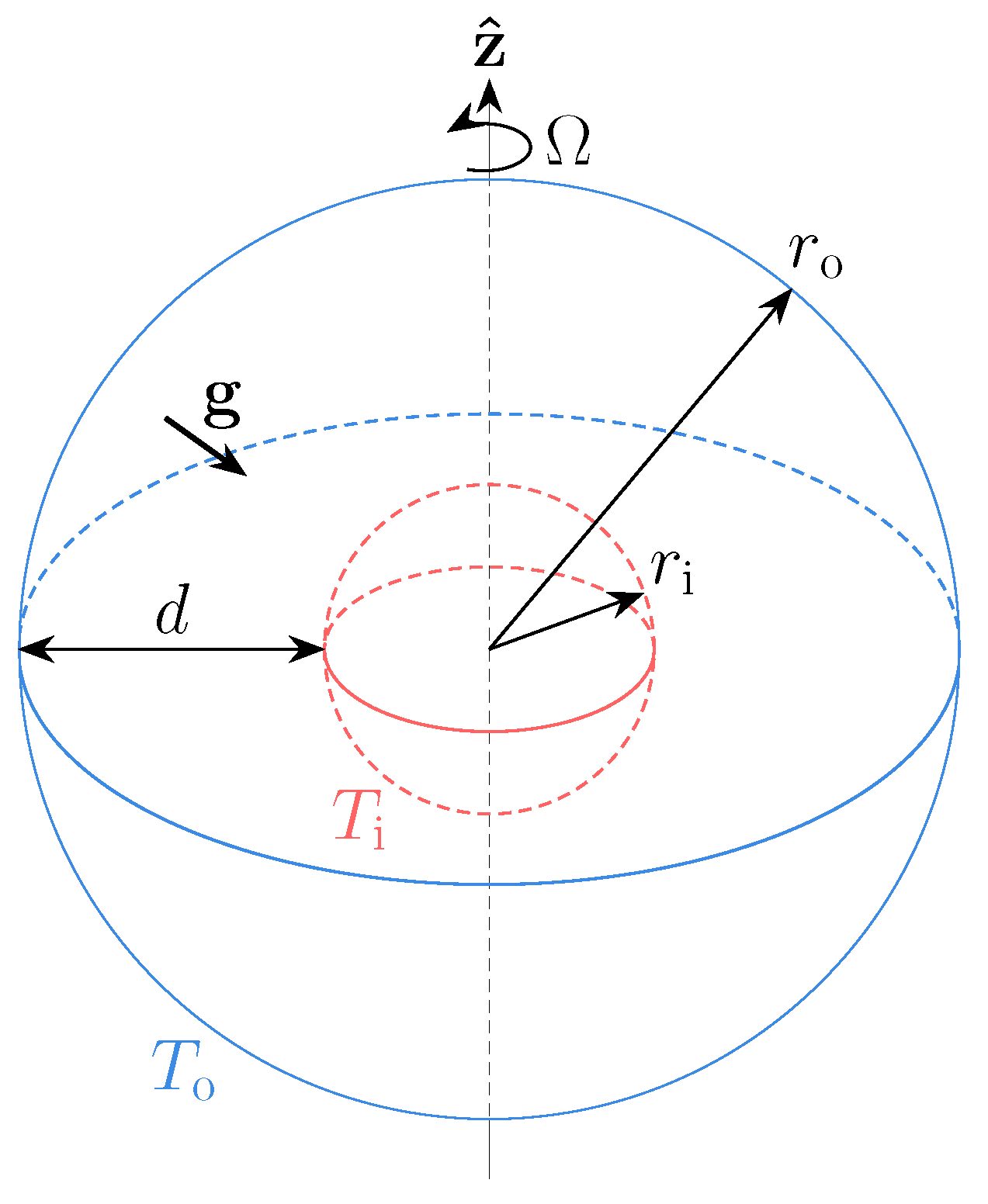
Figure 1. Schematic diagram of the problem. The inner spherical surface at r = r i is held at temperature T = T i and the outer spherical surface at r = r o is held at temperature T = T o < T i . The system rotates about the vertical (z-direction) with rotation rate, Ω . The gap width is d = r o r i and gravity acts radially, g = g r r ^ .
Fluids 10 00237 g001
Figure 2. Dependence of critical values on the Prandtl number, Pr, for several values of the Ekman number, E, in the case of differential heating with purely no-slip boundary conditions and radius ratio χ = 0.35 . (a) Critical Rayleigh number, (b) critical frequency, (c) critical azimuthal wavenumber. Critical values found by Christensen and Aubert (★) [12] and Fan et al ( ) [10] are also shown. The best-fit curves are given by Equation (10) with fitting parameters given in Table 2.
Fluids 10 00237 g002
Figure 3. The radial component of the velocity field at onset plotted in an equatorial slice for purely no-slip boundary conditions, χ = 0.35 , differential heating (top half), internal heating (bottom half), E = 10 4 (left half of each panel), E = 10 5 (right half of each panel), and for (a) Pr = 0.1 , (b) Pr = 1.0 , and (c) Pr = 100.0 . Red and blue represent positive and negative values, respectively.
Fluids 10 00237 g003
Figure 4. Comparison of critical parameter values as functions of the Prandtl number, Pr, for several values of the Ekman number, E, and different boundary conditions with radius ratio, χ = 0.35 . Results are shown for each heating configuration: (a) differential heating (hollow symbols); (b) internal heating (solid symbols). Boundary conditions are indicated by symbols: purely no-slip (◇); purely stress-free ( ); no-slip on the inner boundary and stress-free on the outer boundary (✩).
Fluids 10 00237 g004
Figure 5. The relative difference between the critical Rayleigh numbers of purely no-slip and purely stress-free boundary conditions. The quantity 1 Ra c SF / Ra c NS is plotted against the Prandtl number, Pr, for different values of the Ekman number, E, with χ = 0.35 and the case of (a) differential heating and (b) internal heating.
Fluids 10 00237 g005
Figure 6. The critical radius, s c , as a function of the Prandtl number, Pr, for two values of the Ekman number, E, with χ = 0.35 , purely no-slip boundary conditions, and for the case of internal heating.
Fluids 10 00237 g006
Figure 7. Dependence of critical values on the radius ratio, χ , for several values of the Ekman number, E, for the case of differential heating with purely no-slip boundary conditions and Prandtl number, Pr = 1 . (a) Critical Rayleigh number, (b) critical frequency, (c) critical azimuthal wavenumber. Critical values found by Al-Shamali et al. [34] (★) and Barik et al. [31] ( ) are also shown. The best-fit curves are given by Equation (11) with fitting parameters given in Table 3.
Fluids 10 00237 g007
Figure 8. The radial component of the velocity field at onset plotted in an equatorial slice for purely no-slip boundary conditions, Pr = 1 , differential heating (top half), internal heating (bottom half), E = 10 4 (left half of each panel), E = 10 5 (right half of each panel), and for (a) χ = 0.2 , (b) χ = 0.45 , (c) χ = 0.65 , and (d) χ = 0.8 . Red and blue represent positive and negative values, respectively.
Fluids 10 00237 g008
Figure 9. Comparison of critical parameter values as functions of radius ratio, χ , for several values of the Ekman number, E, and different boundary conditions with Prandtl number, Pr = 1 . Results are shown for each heating configuration: (a) differential heating (hollow symbols); (b) internal heating (solid symbols). Boundary conditions are indicated by symbols: purely no-slip (◇); purely stress-free ( ); no-slip on the inner boundary and stress-free on the outer boundary (✩).
Fluids 10 00237 g009
Figure 10. The relative difference between the critical Rayleigh numbers of purely no-slip and purely stress-free boundary conditions. The quantity 1 Ra c SF / Ra c NS is plotted against radius ratio χ for different values of the Ekman number E with Prandtl number Pr = 1 and the case of internal heating.
Fluids 10 00237 g010
Figure 11. The critical radius, s c , as a function of χ for two values of the Ekman number, E, with Pr = 1 , purely no-slip boundary conditions, and for the case of internal heating (+) and differential heating (◇). The grey dashed line is given by s c / r o = χ , indicating the position of the inner boundary.
Fluids 10 00237 g011
Figure 12. Dependence of the critical Rayleigh number on radius ratio for various definitions of Ra c based on nondimensional set-ups discussed in Section 2.3. All results shown are for E = 10 5 and Pr = 1 with purely no-slip boundary conditions. Results are displayed for AN-1 (as used in this work), AN-2 (as used by [19]), and AN-4 (as used by [31,34]). The curves are formed by connecting the points of each case.
Fluids 10 00237 g012
Table 1. Conversions for the Rayleigh number between nondimensionalisations. The Rayleigh number of AN-1 is Ra and the table provides the equivalent value for the other nondimensionalisations.
AN-2AN-3AN-4
Ra r o = ( 1 χ ) 5 Ra Ra Δ T = [ Γ ( χ ) ] 1 Ra Ra Δ T g o = ( 1 χ ) 1 Ra Δ T
Table 2. Fitting parameters a i and b i for the critical value best-fit curves from Figure 2 (for a system with χ = 0.35 , differential heating, and purely no-slip boundaries). i = 1 refers to Equation (10a) for Ra c , i = 2 refers to Equation (10b) for m c , and i = 3 refers to Equation (10c) for ω c .
E a 1 b 1 a 2 b 2 a 3 b 3
10 4 1.556 × 10 5 0.522 6.938 0.073 1.365 × 10 2 0.364
3 × 10 5 6.459 × 10 5 0.609 10.450 0.140 3.230 × 10 2 0.356
10 5 2.435 × 10 6 0.677 15.024 0.184 6.981 × 10 2 0.352
Table 3. Fitting parameters a i , b i , and c i for the critical value best-fit curves from Figure 7 (for a system with Pr = 1 , differential heating, and purely no-slip boundaries). The fitting parameters are used in Equation (11), where C 1 = Ra c , C 2 = m c , and C 3 = ω c .
E a 1 b 1 c 1 a 2 b 2 c 2 a 3 b 3 c 3
10 4 3.407 × 10 5 2.355 0.123 4.172 × 10 2 10.147 4.273 9.751 × 10 4 13.165 7.402
3 × 10 5 3.540 × 10 6 0.390 0.920 1.235 × 10 3 11.636 5.081 2.477 × 10 5 13.320 7.470
10 5 2.662 × 10 7 1.096 1.703 2.665 × 10 3 12.486 5.553 3.746 × 10 5 12.620 7.059
Disclaimer/Publisher’s Note: The statements, opinions and data contained in all publications are solely those of the individual author(s) and contributor(s) and not of MDPI and/or the editor(s). MDPI and/or the editor(s) disclaim responsibility for any injury to people or property resulting from any ideas, methods, instructions or products referred to in the content.