Abstract
In this work, a novel type of shell and helically coiled heat exchangers (SHCHEXs) that are used extensively in numerous applications has been numerically and experimentally studied. A low-cost and easily applicable design for enhancing the heat exchange rate in a shell and helically coiled heat exchanger has been developed within the scope of this study. In this context, a SHCHEX has been developed with an internal guiding pipe and spirally formed fins with the purpose of leading the fluid in the cold loop over the coil where hot fluid flows inside it. Numerical simulations were carried out in this study for determining how the new changes including nonporous and porous spiral fins affected heat transfer in the system. In the experimental part of the current research, a heat exchanger with a guiding pipe and nonporous spiral fins has been fabricated and its thermal behavior tested at various conditions utilizing water and MnFe2O4-ZnFe2O4/water hybrid-type nanofluid. Both numerical and experimental findings of this research exhibited positive effects of using new modifications including spiral fin integration. Overall findings of this work clearly exhibited a significant effect of the spiral fin medication and MnFe2O4-ZnFe2O4/water-hybrid magnetic nanofluid utilization on the thermal performance improvement in the heat exchanger. Experimentally determined findings showed that using MnFe2O4-ZnFe2O4/water in the hot loop of the SHCHEX improved the heat transfer coefficient of the heat exchanger by an average ratio of 16.2%. In addition, mean variation between the experimentally obtained exit temperature and numerically achieved one was 3.9%.
1. Introduction
One of the most significant issues facing the industrial sector today is the need to shift toward more environmentally friendly and sustainable technologies, due to the great threat that carbon emissions pose to our planet. As industrialization accelerates, energy demand increases exponentially. However, it seems unlikely that all branches of industry will be able to adapt to eco-friendly practices at the same pace. In this transformation process, renewable energy sources can play a supportive role, but their implementation requires multi-dimensional planning. At this point, the key solution emerges as designing efficiency-oriented systems that aim to achieve the highest productivity with the least resource consumption.
Heat exchangers (HEXs) are fundamental devices that enable heat transfer between fluids at different temperatures without mixing them, typically accomplished via a solid surface such as tubes, plates, etc. They are widely used in many fields, including cooling, heating, and energy conversion processes, and many academic studies are conducted to improve their thermal performance. In industrial applications, Shell and Helically Coiled Heat Exchangers (SHCHEXs) are commonly preferred in areas such as cooling systems, waste heat recovery, chemical processes, thermal storage, and the food industry due to their higher thermal performance compared to conventional shell and tube HEXs. Compared to traditional straight-tube HEXs, the SHCHEX’s design offers several advantages since it uses a helically coiled tube contained in a cylindrical shell. The working fluid undergoes constant direction changes as it passes through the coiled tube, creating centrifugal forces that have a big impact on the dynamics of the flow. These forces encourage turbulence and secondary flows, which increase fluid layer mixing and heat exchange. In comparison to conventional straight-tube HEXs, this phenomena enables SHCHEXs to attain higher heat transfer rates. Additionally, the coiled form makes the design more compact and efficient by extending the area accessible for heat transfer in the same volume. The performance of SHCHEXs can be optimized for particular needs by varying the design parameters, containing the shell configuration, pitch, and coil diameter. SHCHEXs are a flexible option for thermal energy management because of their flexibility to adapt to the needs of a variety of sectors. Furthermore, improvements in material and manufacturing processes have strengthened SHCHEXs’ stability and efficacy.
Different kinds of SHCHEXs have been experimentally and numerically examined in a number of papers published in the open literature. In a study conducted by Maghrabie et al. [1], they proposed a SHCHEX and experimentally investigated the impact of the inclination angle over the thermohydraulic performance of the HEX. Dizaji et al. [2] applied exergy methodology in analyzing the influence of flow and geometrical factors over the efficiency of a SHCHEX. Maghrabie et al. [3] experimentally analyzed the impact of utilizing some nanofluids (NFs) on the efficiency of a SHCHEX at varying placements. Andrzejczyk and Muszynski [4] experimentally developed a core-fin design with the aim of upgrading the thermal performance of a SHCHEX. In order to improve the heat exchange rate, Jamshidi et al. [5] experimentally investigated a SHCHEX by analyzing the effects of geometrical elements like coil pitch and diameter as well as flow characteristics under laminar flow conditions. Khorasani and Dadvand [6] experimentally examined the influence of bubble injection over the thermohydraulic behavior of a horizontally placed SHCHEX. In another work, Khorasani et al. [7] manufactured a SHCHEX and examined the impact of bubble injection over the general behavior of the HEX. Fuxi et al. [8] used CFD and artificial neural network methods for investigating the impacts of various pitches and hybrid-type nanofluid on the performance of a SHCHEX. Barzegarian et al. [9] investigated water-based Al2O3-gamma NFs to enhance the thermal performance of a shell and tube HEX.
The heat transfer rate of energy conversion systems, such as HEXs, can be increased using different methods [10,11,12]. Two popular techniques for increasing the heat transfer rate are the use of porous media and an extended heat transfer area [13,14,15]. Zing et al. [16] used a numerical approach for analyzing porous material utilization for improving the cooling efficiency of HEXs using various NFs. Al-Sammarraie and Vafai [17] used a numerical method for investigating the thermohydraulic behavior of a convergent tubular HEX. Güngör et al. [18] improved the heat exchange rate in a SHCHEX by adding disc- and ring-shaped fins for distributing the fluid flow on the helically coiled tube. Solanki and Kumar [19] increased the thermal performance of a SHCHEX utilizing a dimpled-type coiled tube in the system. In another study, Solanki and Kumar [20] used a dimpled helically coiled inside of a SHCHEX for improving heat transfer in the system. Zolfagharnasab et al. [21] investigated porous-type tubular HEXs to be utilized for thermal energy recovery and exhibited a significant effect on the thermal improvement by utilizing porous material. Andrzejczyk and Muszynski [22] used different baffle integrations to a SHCHEX with the aim of raising the overall efficiency of the HEX. Also, several studies have employed numerical techniques, including the CFD method to analyze different energy systems [23,24,25]. Zhang et al. [26] utilized the CFD approach to analyze the effect of mounting a spherical corrugation in a SHCHEX over the behavior of the system. Abu-Hamdeh et al. [27] applied the CFD method for simulating the thermohydraulic characteristics of a sector-by-sector-type HEX.
Because of their poor thermal characteristics, using traditional working fluids like water and oil might impede heat transfer in energy systems [28,29]. In order to improve the fluids’ thermal characteristics, the use of nanoparticles in the working fluid of thermal systems, including HEXs, has gained attention in recent years. With their remarkable thermal characteristics, the resulting fluids, known as nanofluids (NFs), have the potential to significantly improve a system’s performance [30,31]. A number of factors, such as the particle ratio, size, shape, and specifications of the used base fluid, significantly affect the thermal behavior of NFs [32,33,34]. Elmnefi and Abdullah [35] utilized TiO2 and Al2O3 containing NFs to enhance the overall performance of a shell- and tube-type HEX. Afshari and Muratçobanoğlu [36] utilized Fe3O4/water NF to improve the heat exchange rate in spiral-type mini channels. Naik and Vinod [37] tested CuO, Al2O3, and Fe2O3 including NFs in a SHCHEX in order to enhance the efficiency and showed a significant impact of the nanoparticle ratio, working temperature, and flow rate over the performance. Güngör et al. [38] used water-based Al2O3-TiO2 including hybrid NF for enhancing the efficiency of a SHCHEX. Srinivas and Vinod [39] used Al2O3/water, CuO/water, and TiO2/water single NFs in a SHCHEX and provided evidence that the CuO/water NF exhibited better performance among tested NFs. Behera et al. [40] experimentally developed a shell- and tubular-type HEX with varying forms and improved the performance of the HEX utilizing the CuO-ZnO/water-hybrid NF. Gaur et al. [41] investigated the effect of the particle shape of NF containing a Graphene platelets, MWCNT, Fe3O4, and Al2O3 on the overall efficiency of a triple-tubular-type HEX. Said et al. [42] used experimental, CFD, and artificial intelligence methods in order to determine the impact of MWCNTs/water NFs utilization in a solar-powered HEX on its thermal behavior. Behrozifard et al. [43] significantly improved the efficiency of a plate HEX utilizing Al2O3 and Graphene containing working fluids in the system. Sheikholeslami et al. [44] numerically examined the effect of using a helical turbulator and copper oxide including NF on the overall behavior of a tubular HEX. Chandran et al. [45] developed a tubular-type HEX to be utilized in a solar energy-based heater and used TiO2/water single NFs for enhancing the performance of the system. Kumar and Sonawane [46] utilized Fe2O3/ethylene glycol and Fe2O3/water NFs for improving the performance of a shell and tube HEX. Bhanvase et al. [47] experimentally examined the impact of using water-based polyaniline NF on the characteristics of a vertically positioned-type helically coiled HEX.
Using two or more different nano-sized particles, also known as hybrid-type NFs, could improve the overall performance of NFs as working mediums. As is well known, single-type nanoparticles cannot meet all of the desired requirements. Thus, because of their potential to provide improved thermal properties through synergistic action, hybrid-type nanofluids are promising candidates for application in HEXs [48,49,50,51].
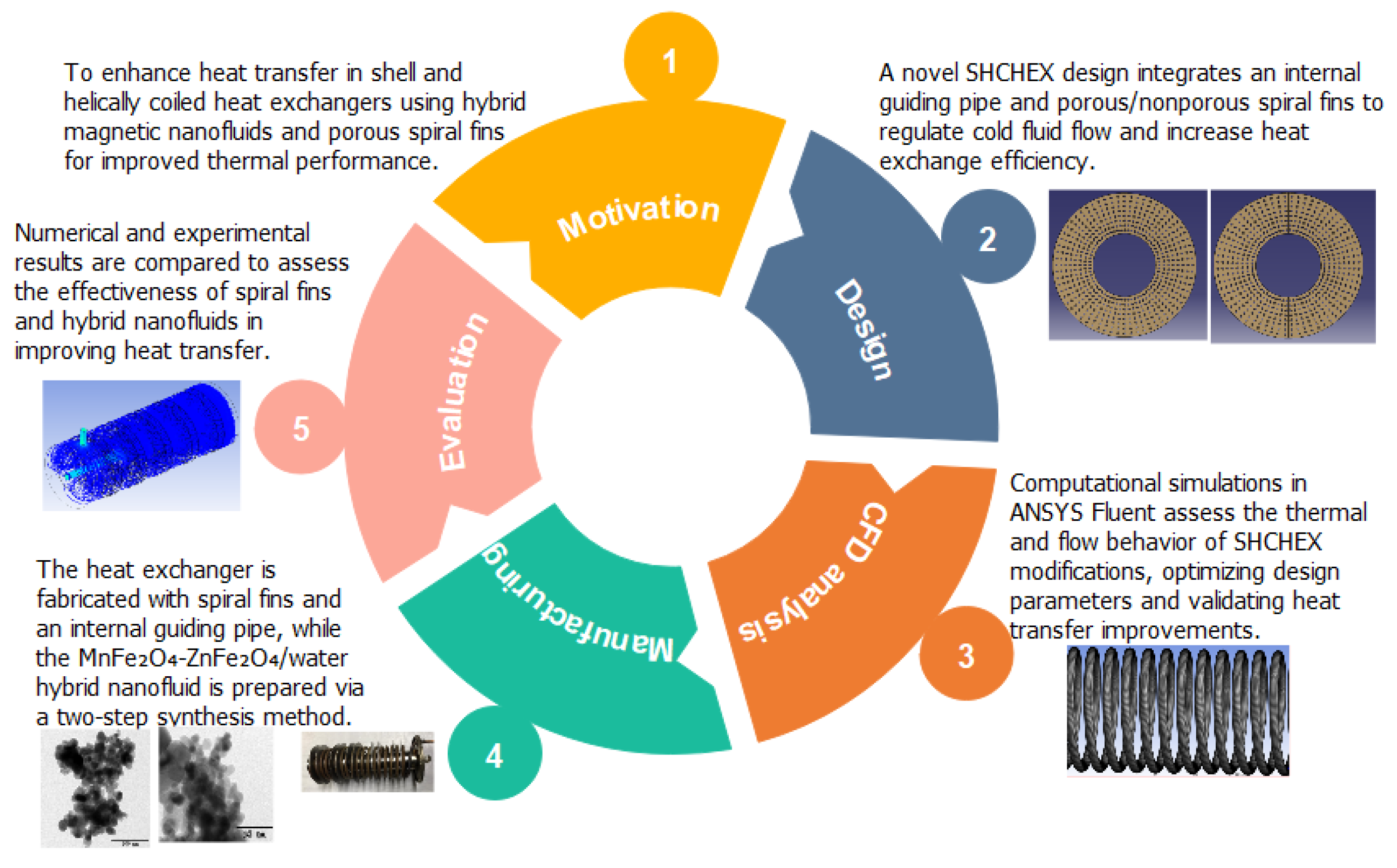
According to the available studies in the literature, using some methods such as fin integration and utilizing NF could significantly enhance heat transfer in the HEXs. Previously, Tuncer et al. [52] and Güngör et al. [18] utilized longitudinal and circular fins with the aim of increasing the heat transfer area and consequently the thermal performance of their developed SHCHEXs. They also tried to guide water flow in the helically coiled tube where energy exchange occurs between two loops. In this work, different from similar previous studies that investigated various methods for improving the performance of the SHCHEXs, spiral-type fins have been utilized for distributing water flow in the cold loop on the coil in a modified SHCHEX with an additional internal guiding tube to upgrade heat transfer. This is the first time that a simultaneous utilization of an internal guiding pipe and spiral-type fins has been applied in order to enhance the thermal performance of a SHCHEX. Adding an internal tube into the SHCHEX extended the flowing time period of the water in the system, regulated fluid flow, guided the water flow on the helically tube, and significantly improved the heat exchange rate. Integrating spiral-type fins to the SHCHEX more importantly improved the contact among the cold fluid and the helically coiled tube by creating swirl flow inside the heat exchanger. Also, comprehensive numerical simulations have been conducted to specify the impacts of using an additional internal tube, utilizing nonporous spiral fins, porous spiral fins, and nanofluid in the SHCHEX. Moreover, for the first time, the MnFe2O4-ZnFe2O4/water hybrid-type magnetic nanofluid has been experimentally investigated as a working medium in the developed spiral fin-integrated SHCHEX to obtain more improvements in the heat transfer. Figure 1 briefly represents the main steps of the present study.
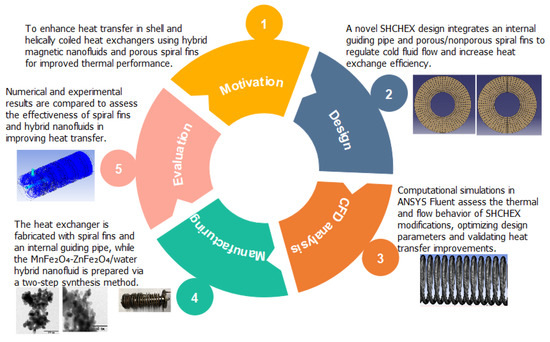
Figure 1.
Main steps of the present study.
2. Approach and Methodology
2.1. Computational Analysis
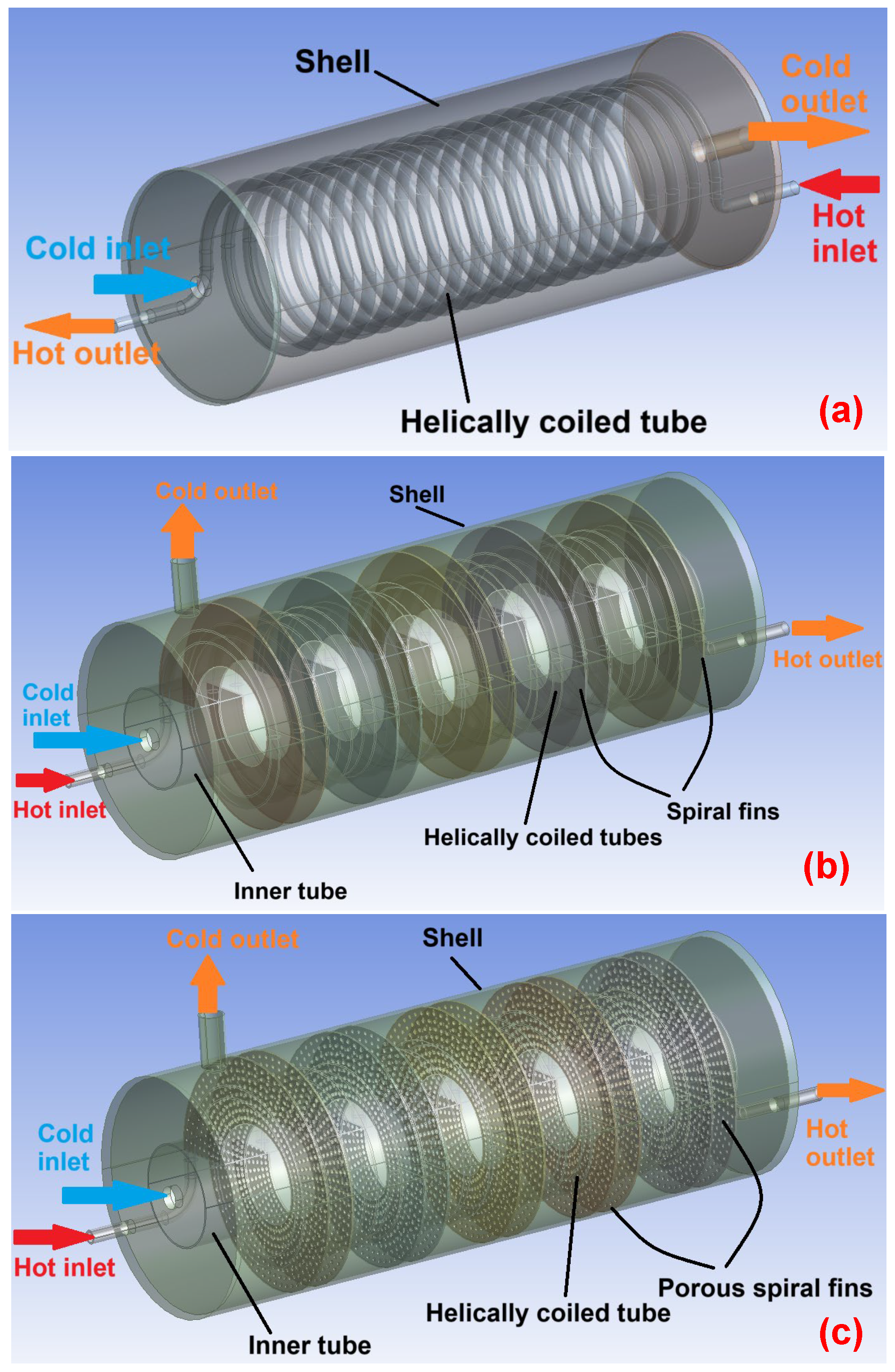
In the current part of this research, a SHCHEX with various modifications has been numerically examined to determine its flow and thermal behavior. In this context, the flow and thermal characteristics of SHCHEXs with various designs for different were simulated by applying the CFD method using ANSYS Fluent 2024R1 software. Determining the proper configuration for the SHCHEX and specifying the impact of employing NF in the system are the main objectives of the numerical simulations in this work. In light of the existing studies in the literature, three different configurations for the SHCHEX have been developed. The developed geometries for three SHCHEX including conventional SHCHEX and modified SHCHEXs are presented in Figure 2. The first SHCHEX which is shown in Figure 2a is a conventional SHCHEX with no modification. In order to lead the cold water across the helically coiled tube and prolong the water’s presence duration inside the system, the second SHCHEX (Figure 2b) includes a different configuration with an extra guiding tube. Additionally, spiral-type fins were added to HEX to increase the contact among the cold fluid and the coil and obtaining swirl flow. These changes could improve the SHCHEX’s heat exchange by controlling the cold loop flow and guiding the cold water over the coil, which is where energy transfer takes place. Similar in design to the second heat exchanger, the third SHCHEX (Figure 2c) is altered by the addition of porous spiral fins and an additional tube to the HEX. This means that the porosity of the spiral fins is the sole thing that separates the second and third SHCHEX. Figure 3 represents the location of nonporous and porous spiral-type fins inside the SHCHEX. Figure 4 represents a top view of the first and second porous spiral fins. As seen in Figure 4, the position of the perforations in two consecutive fins are different in order to increase turbulence intensity. Table 1 represents the developed HEXs’ dimensional parameters and their values. Adding the guiding tube and spiral fin integration are the distinctions between the proposed three SHCHEXs which all have identical dimensional values.
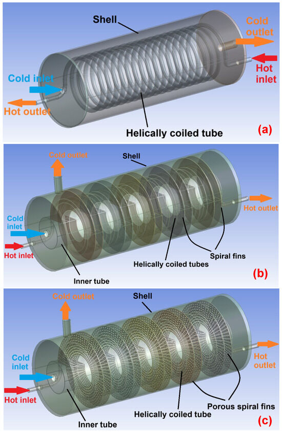
Figure 2.
Geometries and boundary conditions of three HEXs: (a) conventional HEX, (b) nonporous spiral fin-integrated HEX; (c) porous spiral fin-integrated HEX.
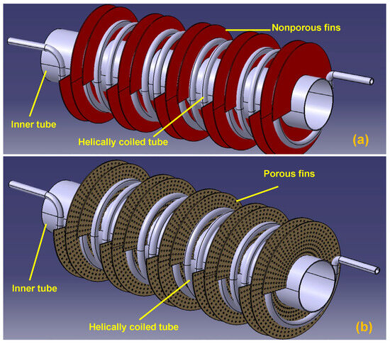
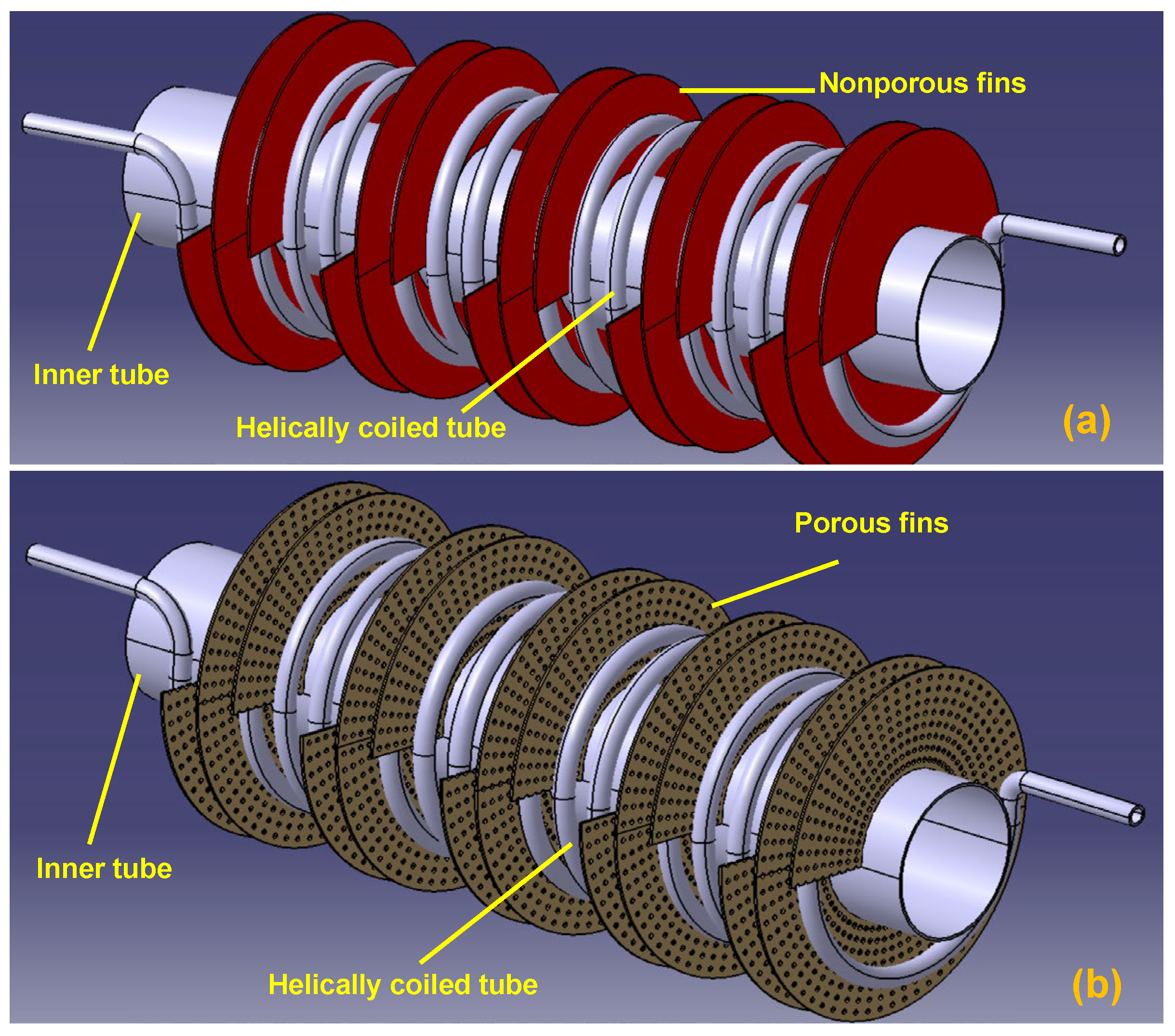
Figure 3.
Location of spiral-type fins inside the HEX; (a) nonporous spiral fins; (b) porous spiral fins.
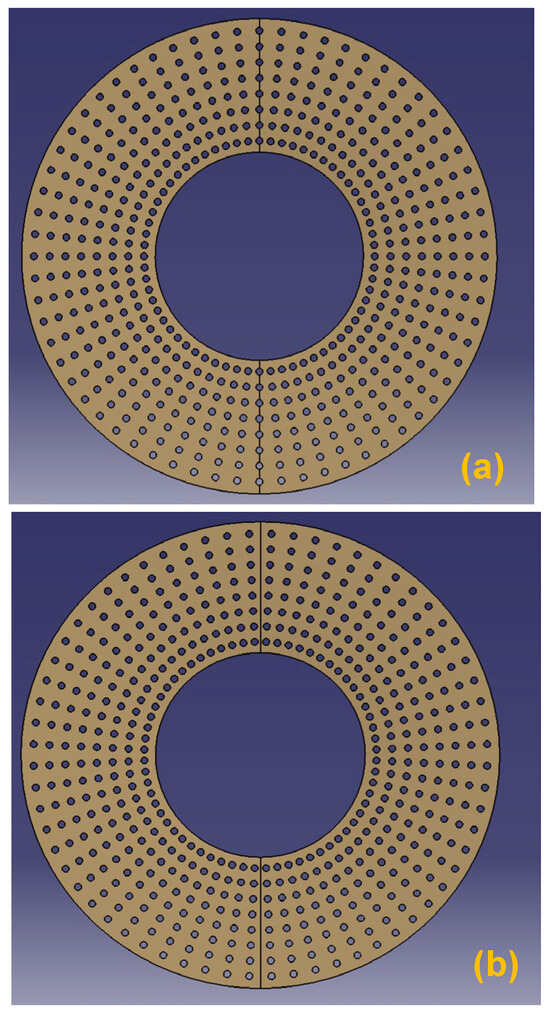
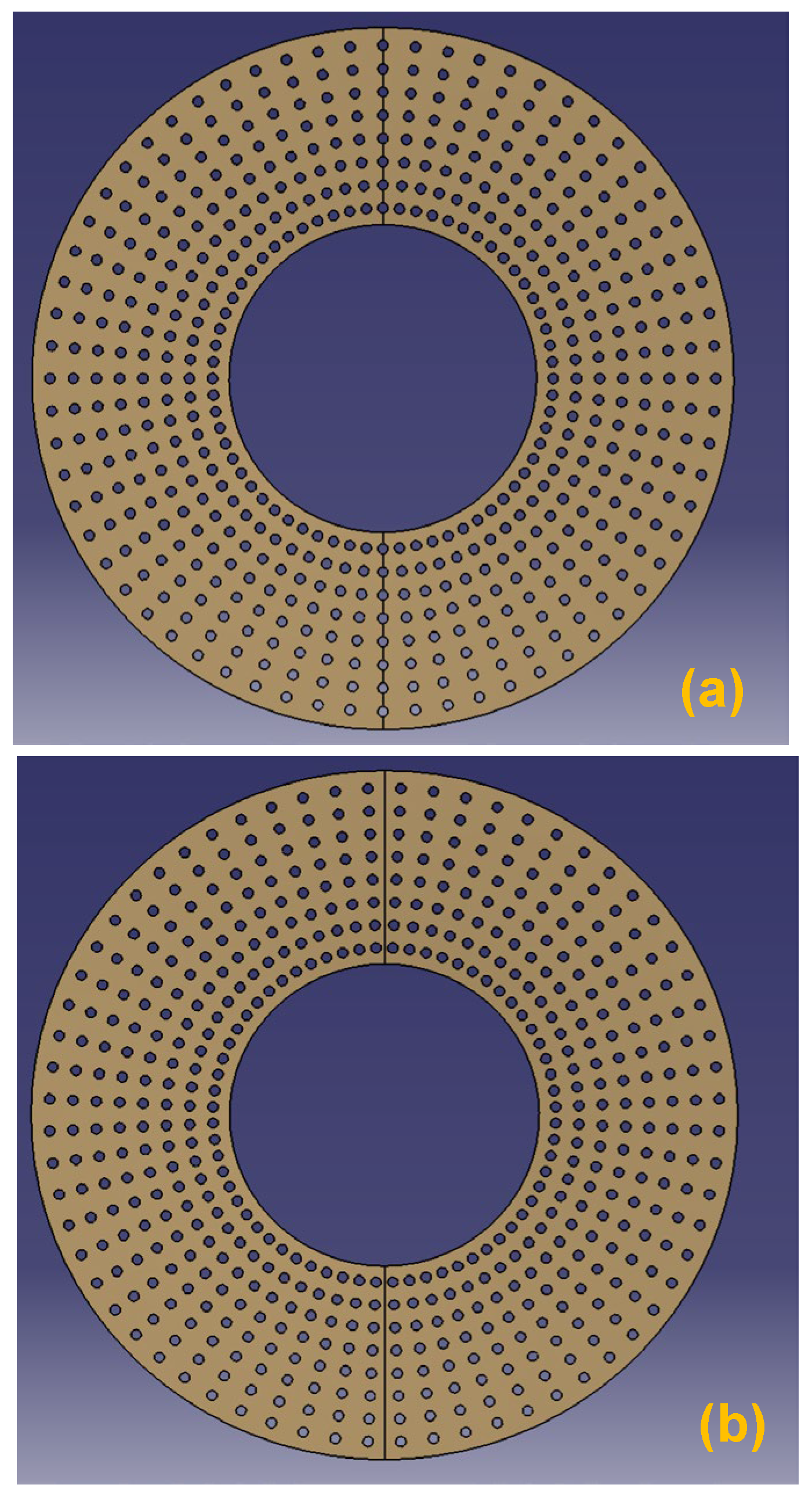
Figure 4.
A top view of porous spiral fins; (a) first spiral fin over the inner tube; (b) second spiral fin over the inner tube.

Table 1.
The developed HEXs’ dimensional parameters and their values.
A proper and high-quality mesh configuration for the investigating domain must be generated in order to get reliable numerical results. Figure 5 illustrates the mesh view of the HEX with spiral fins in the cold fluid and spiral fins, a coiled tube, and a magnified view of nonporous spiral fins and porous spiral fins. Increasing the mesh element number was performed for all domains. However, finer mesh elements were applied for the zones that have a higher effect in obtaining reliable results. For the spiral fins, coil part, and regions near the tube and spiral fins, finer mesh elements were used to provide precise simulation outcomes.
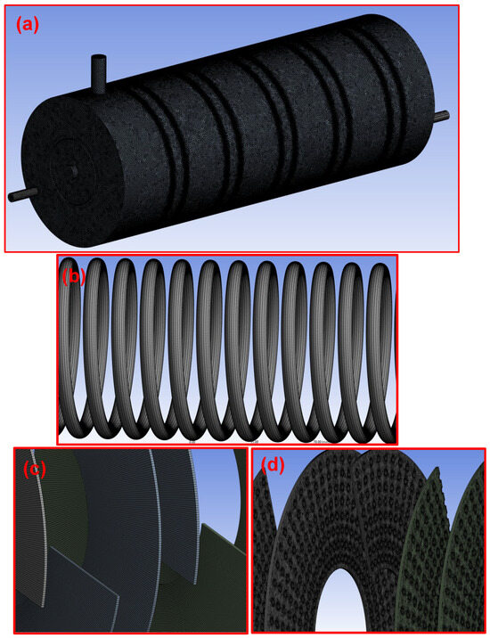
Figure 5.
Mesh view of the HEX with spiral fins; (a) a view of cold fluid and spiral fins; (b) coiled tube; (c) a view of nonporous spiral fins; (d) a view of porous spiral fins.
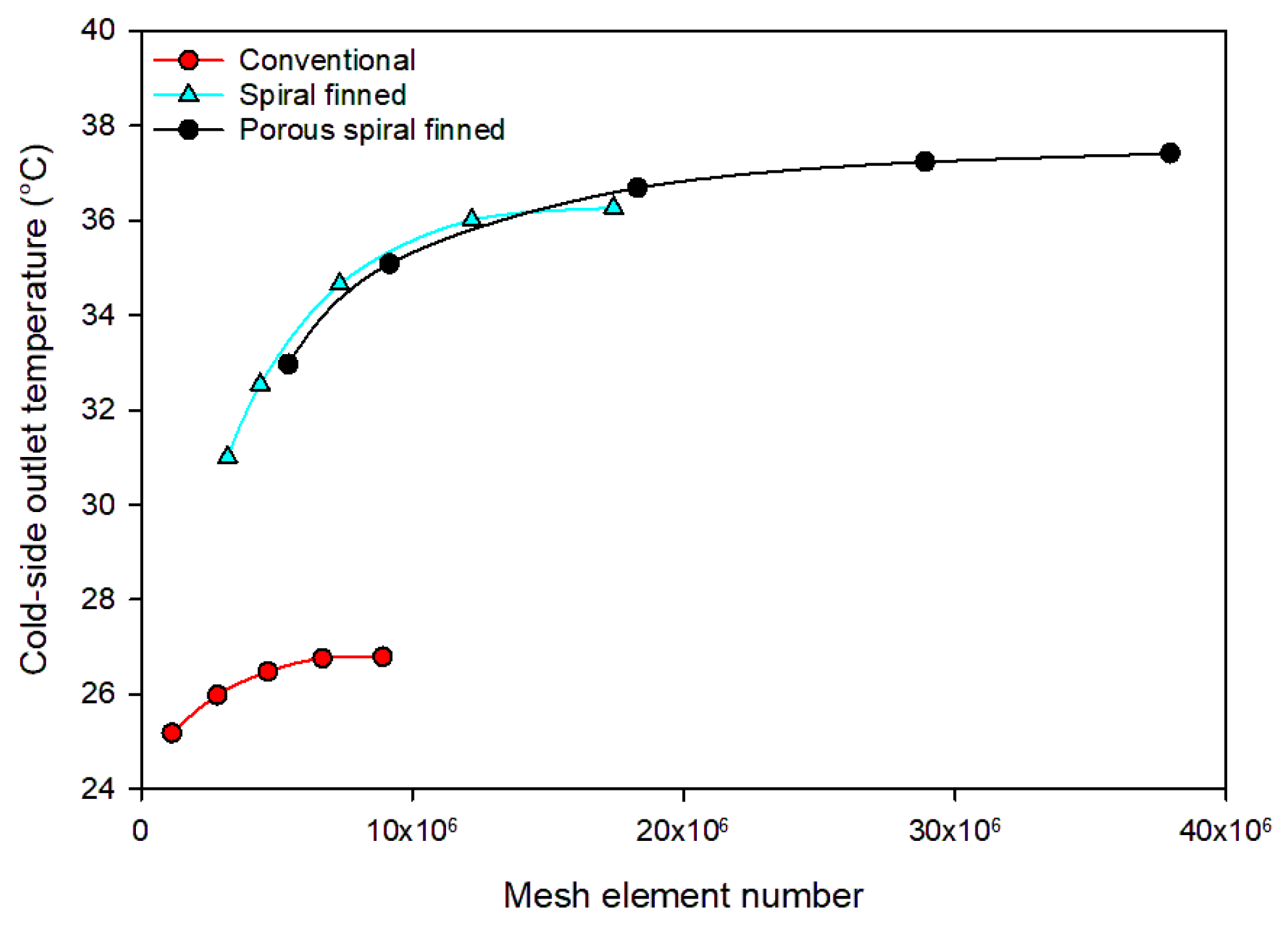
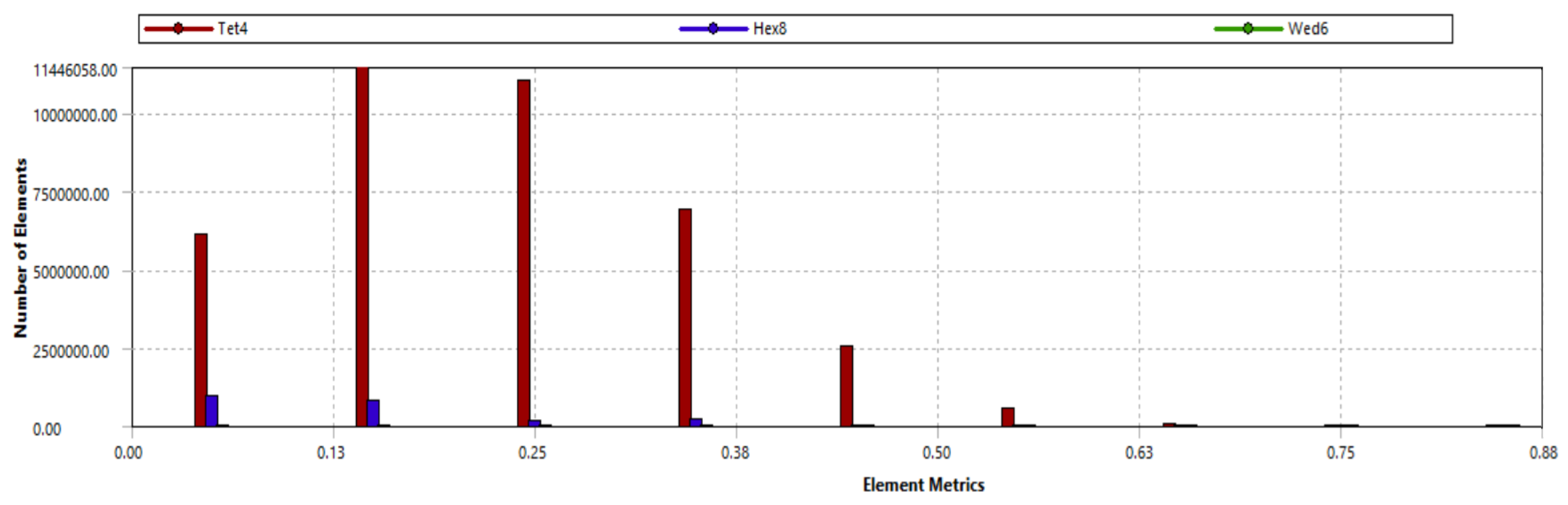
A significant parameter that directly affects the accuracy of the modeling is the meshes generated for the SHCHEXs. In the current research, mesh independency analyses were conducted to identify the best mesh configuration for each SHCHEX. Several mesh structures with different mesh elements were developed in order to get the correct configuration for each designed HEX. To obtain the proper mesh structure, CFD simulations were performed on each generated mesh. Figure 6 illustrates the variation of the outlet temperature of the HEXs via the mesh number by examining different mesh configurations. Figure 7 represents the whole-domain mesh structure statistics data for porous spiral fin-integrated HEX. The quality of the selected mesh can be evaluated by considering several features. One helpful measure of the quality of the generated configuration could be the skewness factor. The maximum values of the skewness parameter for conventional SHCHEX, nonporous spiral fin-integrated SHCHEX, and porous spiral fin-integrated SHCHEX were 0.80, 0.84, and 0.87, respectively. Additionally, the mean values of the skewness parameter for conventional SHCHEX, nonporous spiral fin-integrated SHCHEX, and porous spiral fin-integrated SHCHEX were 0.19, 0.21, and 0.24, respectively.
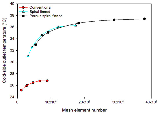
Figure 6.
Variation of outlet temperature of the HEXs via mesh number by examining different mesh configurations.
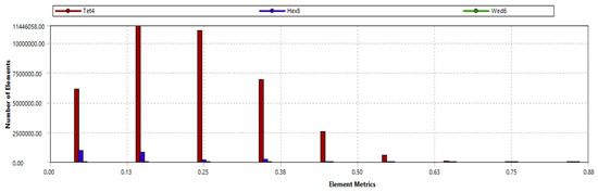
Figure 7.
The whole-domain mesh structure statistics data.
In the current work, the Fluent program was utilized to simulate the overall behavior of the conventional SHCHEX and spiral fin-integrated SHCHEXs. The conservation of mass, momentum, and energy are the governing equations which are employed in the numerical analysis of the SHCHEXs. Furthermore, it is crucial to use an appropriate turbulence model to simulate flow behavior inside the SHCHEXs. Consequently, several widely utilized turbulence models have been examined including similar studies that assessed various types of HEXs [53,54]. Lastly, the option of model was chosen to be employed in the current study’s numerical analysis part. In the study’s simulation part, SHCHEXs have been modeled under the steady-state conditions. Also, the SIMPLE-Consistent approach was selected to be used in the coupling pressure and velocity modeling procedure. Moreover, the second-order upwind method was selected to gain momentum and energy balances; for velocity, for continuity, and for energy were adjusted as the convergence condition.
The definition of mass conservation is [55] as follows:
The conservation of momentum could be described as [55] follows:
where represents pressure, represents gravitational force, shows external force, and illustrates stress tensor.
Additionally, conservation of energy is described as [55] follows:
In this case, stands for heat sources, shows the diffusion of species j, and represents the effective thermal conductivity. Conduction transfer, species diffusion, and viscous distribution are the three energy transfer methods represented by the three terms on the right-hand side of the balance, respectively.
The term E in the energy equation can be written using Equation (4).
where the following expression could be given for sensible enthalpy () for incompressible flows:
displays the mass fraction of species j in Equation (5) and
Lastly, using the model, the turbulence kinetic energy (k) and its dissipation rate () could be obtained as [55] follows:
and denote source terms; , and are constants in the model; and are the inverse Prandtl numbers for and ; illustrates the impact of fluctuating expansion in compressible flow on the overall dissipation rate; illustrates how buoyancy affects turbulence kinetic production; and shows how turbulence kinetic energy is generated from average velocity changes.
Furthermore, and might be used to obtain the turbulent viscosity () as follows:
In the numerical analysis part, the inlet temperature of the cold side was fixed at 9.8 °C, and the temperature of the hot side was set at 45, 50, 55, 60, and 65 °C. Also, three different flow rates between 1.5 and 3.5 lpm for both cold and hot sides were used in the numerical analyses.
2.2. Test Setup
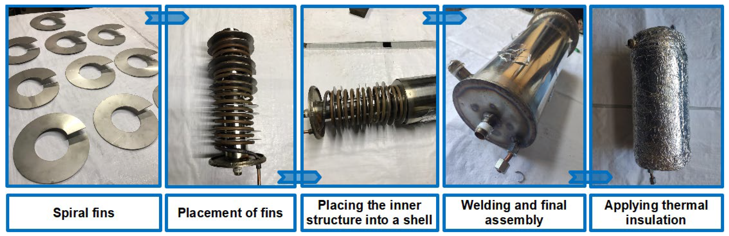
In the experimental part of this study, a spiral fin-integrated SHCHEX has been fabricated considering numerical outcomes and experimentally examined at different conditions. Figure 8 illustrates manufacturing steps of the HEX with nonporous spiral fins. A copper tube with a thickness of 1 mm was utilized for manufacturing the helically coiled part of the HEX. An internal guiding tube in the center of the HEX was used with the purpose of controlling the cold-side flow and upgrading heat transfer in the SHCHEX. Furthermore, spiral-type fins were added to distribute the flow of cold water on the tube, thereby improving heat transfer. Lastly, to minimize thermal energy loss from the HEX to the ambient, the constructed SHCHEX was thermally insulated. Hot fluid flows inside the helically coiled tube of the SHCHEX, while cold fluid flows in the shell loop. Figure 9 represents a detailed diagrammatic illustration of the test setup that was used during the experiments. In the experimental setup, hot water warms up using an electrical resistance that was placed in the hot water reservoir and distributed to the SHCHEX by using a circulation pump. In the test apparatus, some safety precautions were utilized, such as pressure valves and circuit breakers. Additionally, fluid flow on both cold and hot loops were recorded and adjusted using flowmeters which have an accuracy of ±5%. Furthermore, the experimental apparatus includes thermocouples for measuring the temperatures of both hot and cold fluids. Inside the hot water reservoir, a dimmer was employed to modify the desired power for heating water. Moreover, a control system was used in the test apparatus. As previously mentioned, an electrical heater was used to heat the hot fluid inside the hot water reservoir before it was transferred to the SHCHEX’s coiled tube part. On the other hand, the cold water goes through the SHCHEX via the shell loop and quits the HEX after absorbing thermal energy from the coil. Water was used as the working fluid on both sides of the HEX for the performance tests of the constructed SHCHEX with additional internal tube and spiral fins in the first stage of the experimental analyses of this investigation. The MnFe2O4-ZnFe2O4/water hybrid-type magnetic NF has been evaluated as the flowing medium in the hot loop of the SHCHEX for the next stage of the experimental analyses of this current research. For the purpose of conducting a thorough comparison between the two working mediums, the tests involving deionized water and hybrid magnetic NF were carried out under identical boundary conditions. In the experiments for both water and MnFe2O4-ZnFe2O4/water-hybrid magnetic NF, the inlet temperature of the hot side was fixed to a specific temperature. The required values were recorded after steady-state conditions were reached. The performance tests were carried out using hot and cold fluids at three distinct flow rates.
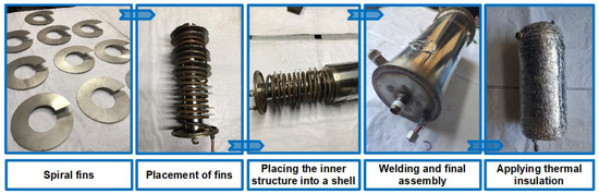
Figure 8.
Manufacturing steps of the HEX with spiral fins.
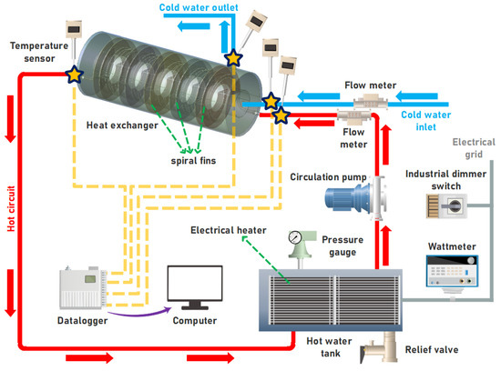
Figure 9.
A diagrammatic illustration of the test setup.
2.3. Nanofluid Preparation Procedure
In the present study, a MnFe2O4-ZnFe2O4/water-hybrid magnetic nanofluid has been selected based on its synergistic thermal and magnetic properties. Compared to noble metal-based nanofluids (e.g., Ag and Au), these ferrite-based materials are more cost-effective and environmentally friendly, making them suitable for large-scale applications. The MnFe2O4-ZnFe2O4 combination provides excellent chemical stability and dispersion in base fluids like water, which reduces agglomeration and sedimentation. Both MnFe2O4 and ZnFe2O4 exhibit high thermal conductivities individually. When combined in hybrid form, they create a synergistic effect, enhancing heat transfer more effectively than mono-nanofluids.
This study’s experimental analysis includes two distinct working mediums containing deionized water and MnFe2O4-ZnFe2O4/water-hybrid magnetic NF and were evaluated in the spiral fin-integrated SHCHEX. The two-step method, which is often advised in the literature, was used in this instance to prepare MnFe2O4-ZnFe2O4/water NF. As a result, dry powder MnFe2O4 and ZnFe2O4 nanoparticles (NPs) were produced using an eight-hour ball milling procedure [56]. Figure 10 illustrates scanning electron microscope views of the obtained MnFe2O4 and ZnFe2O4. The mean size for MnFe2O4 and ZnFe2O4 NPs were between 30 and 55 nm and 8 and 28 nm, respectively. The achieved MnFe2O4 and ZnFe2O4 NPs have purity values of 98.95% and 98.7%, respectively. In the following step, ZnFe2O4+ MnFe2O4 NPs were mixed, with deionized water as the main fluid, in the selected ratio (1% wt./wt.) using a precision balance. It should be stated that the MnFe2O4-ZnFe2O4/water-hybrid magnetic-type NF was prepared at a percent mass ratio of 50:50 (MnFe2O4-ZnFe2O4). A mechanical mixer was used in the adding process of ZnFe2O4-MnFe2O4 NPs into the deionized water. Additionally, Triton X-100 surfactant (0.2% wt./wt.) was added to the prepared solution to enhance the NF’s wetting capabilities and lower surface tension, which produces a stable fluid. Lastly, an ultrasonic bath was employed to increase the MnFe2O4-ZnFe2O4/water NF’s stability. In other words, continuous pulsing was applied to the prepared hybrid, magnetic MnFe2O4-ZnFe2O4/water NF for a time period of 5 h. The thermophysical properties of the prepared hybrid, magnetic MnFe2O4-ZnFe2O4/water NF are other important issues that need further research. In this context, the densities of MnFe2O4-ZnFe2O4/water NF and deionized water have been determined by weighing a specific volume of fluids using a precision balance (device accuracy: ±0.01 g). The AND SV-10 viscometer was used to quantify the deionized water and MnFe2O4-ZnFe2O4/water NF viscosities (device accuracy: ±1%). The fluids’ specific heat capacity has been ascertained through the application of the Differential Scanning Calorimetry (DSC) approach. Accordingly, the heat capacity of the deionized water and MnFe2O4-ZnFe2O4/water NF as working mediums has been determined using a Perkin Elmer Diamond DSC apparatus (device accuracy: ±1%).
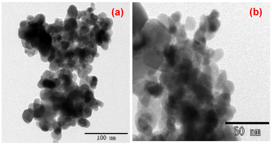
Figure 10.
Scanning electron microscope (SEM) views of utilized nanoparticles: (a) MnFe2O4 and (b) ZnFe2O4..
Finally, the conductivities of the deionized water and MnFe2O4-ZnFe2O4/water were specified using the TPS 500S thermal conductivity measuring system (device accuracy: 5%) utilizing the hot disk technique. The thermophysical specifications of deionized water and MnFe2O4-ZnFe2O4/water NF are illustrated in Table 2.
Table 2.
Thermophysical specifications of water and MnFe2O4-ZnFe2O4/water.
2.4. Calculations
The current section presents and explains the equations used to analyze experimental data. Equations (10) and (11) might be used to determine the heat transfer rate in the SHCHEX’s cold side and hot side (.
In general, heat exchange between the hot and cold parts is unequal due to a number of variables, including heat loss. It is conceivable to suppose that the rates of heat exchange in the both sides are equal in order to simplify calculations. Consequently, it might be provided as the following:
An essential element in the study of thermal behavior is the SHCHEX’s overall heat transfer coefficient, which can be obtained as follows:
here represents the external area of the coil and shows the logarithmic mean temperature difference in the SHCHEX. can be calculated as the following:
The critical Reynolds number is used to specify the flow regime. The critical Reynolds number for the helically coiled tube of the SHCHEX could be written as [57] the following:
Furthermore, the Dean number can be written as follows:
The SHCHEX’s Reynolds number in the cold part could be found as follows [58]:
The uncertainties of the experimental analysis may be influenced by the type of measuring equipment, the test adjustment, the connection points, and the calibration of the devices utilized. It is possible to calculate the total experimental uncertainty using Equation (18) [59].
The temperature, mass flow rate, and heat transfer coefficient are among the factors examined in the study; each has a corresponding uncertainty value. The calculated uncertainty for the measured temperature was ±0.56 °C, and the uncertainty for the mass flow rate was ±5.14%. In addition, for the heat transfer coefficient parameter the uncertainty was calculated as ±6.54%. Khanlari et al. [60] obtained an experimental error value of ±5.36% for the water mass flow rate. In a study conducted by Elshazly et al. [61], the uncertainty value for the heat transfer coefficient parameter was achieved in the range of 4.7–7.0%. Panahi and Zamzamian [62] found that the experimental error for the heat transfer coefficient in their analysis of a helically coil HEX was ±9.17%.
3. Results and Discussion
The experimental and numerical findings of the analysis of the SHCHEXs are shown and explained in this part.
3.1. CFD Simulation Results
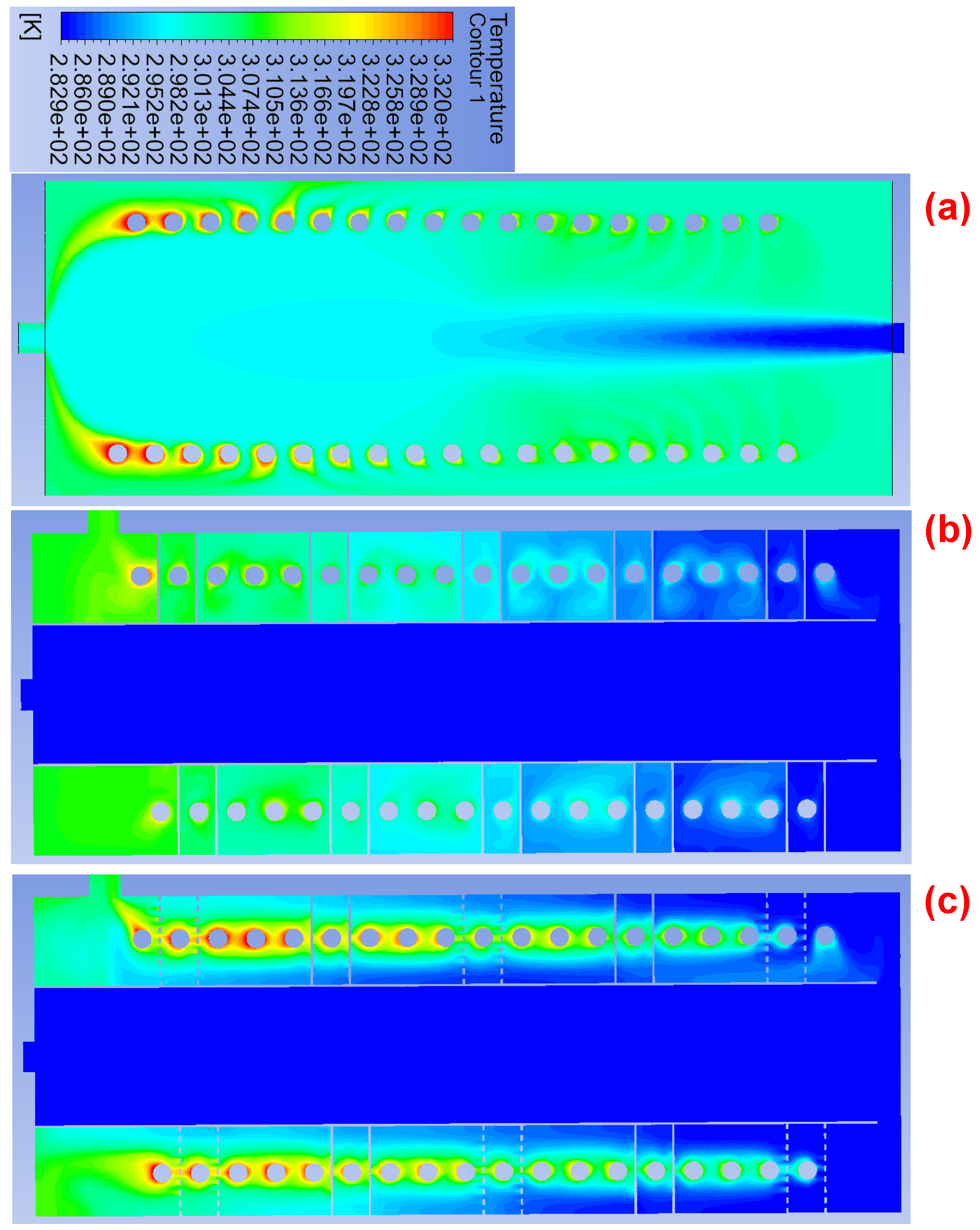
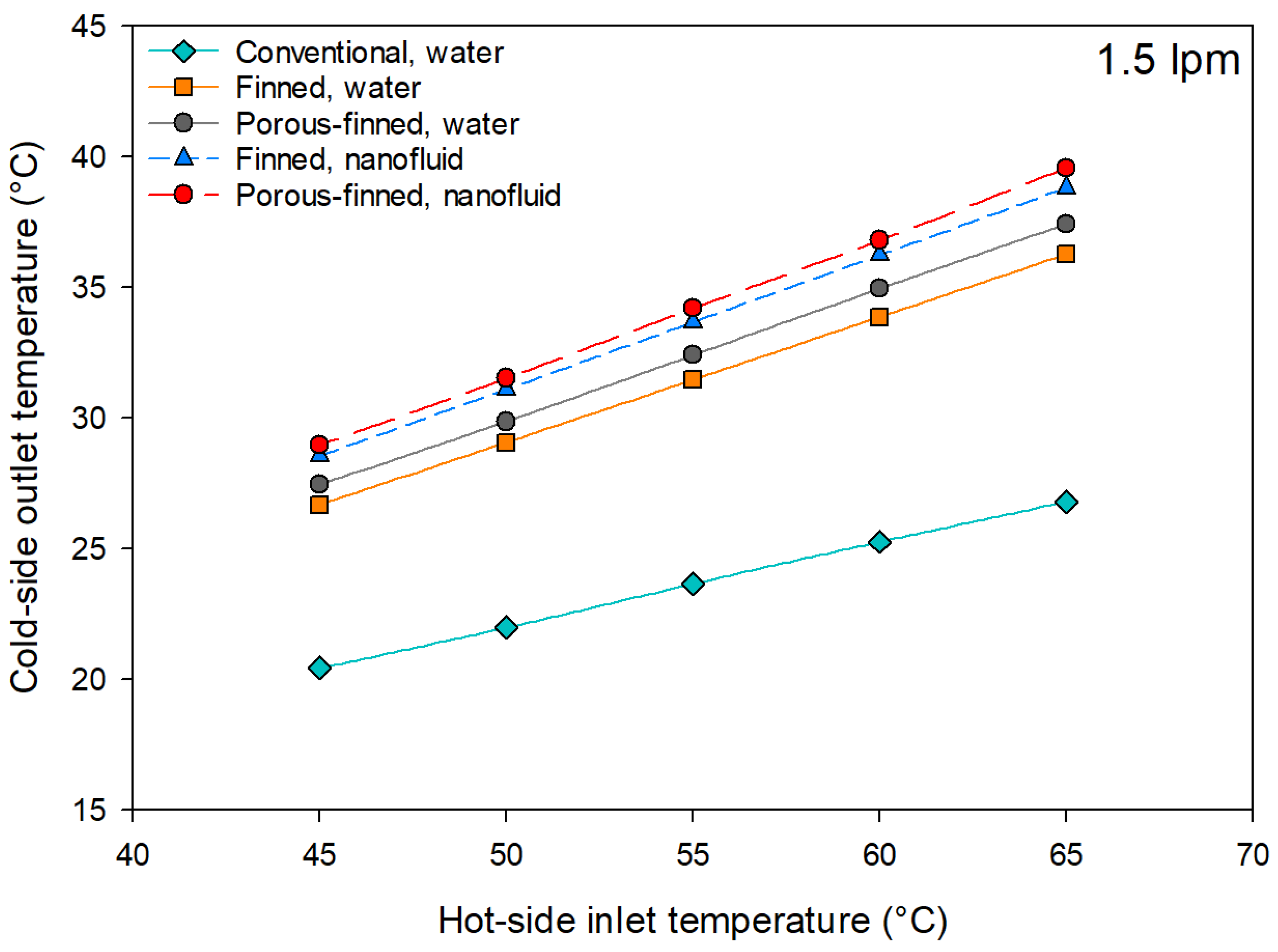
Three SHCHEXs have been numerically designed and examined in this research’s numerical section. Figure 11 presents temperature contour over a plane in the cold loop of the HEXs for the conventional HEX, spiral fin-integrated HEX, and porous spiral fin-integrated HEX. Water passes over the center zone of the HEX in the conventional SHCHEX (Figure 11a) and quickly exits the system. This results in poor system performance since cold water is unable to absorb heat from the hot loop. The impact of integrating additional internal tube and spiral fins to the system is evident when comparing the temperature contour of spiral fin-added HEXs with the conventional HEX. These changes enhanced the contact area between the cold water and the hot loop and prolonged the cold fluid’s presence inside the system. Also, the porous spiral fin-integrated SHCHEX showed a similar thermal behavior with the nonporous spiral fin-added SHCHEX, as seen in Figure 11. But, employing porous spiral fins leads to a greater outlet temperature and more heat being extracted from the hot loop when compared to two other scenarios. Figure 12 illustrates the temperature of the cold loop of three investigated HEXs via the hot side’s temperature. Numerical simulations have been repeated for the spiral fin-integrated HEX and porous spiral fin-integrated HEX using the MnFe2O4-ZnFe2O4/water-hybrid NF. Figure 12 obviously represents the impact of modifying the SHCHEX over the outflow temperature of the cold loop. Both changes significantly raised the outlet temperature and had an important impact on heat transfer. Additionally, the MnFe2O4-ZnFe2O4/water-hybrid NF utilization in the hot side of the HEXs significantly enhanced heat transfer in both modified HEXs. The exit temperature in the spiral fin-integrated SHCHEX on average improved by 32.3% compared to the conventional one. Also, in the porous spiral fin-integrated SHCHEX, the exit temperature of the cold loop on average was enhanced by 37% compared to the traditional HEX. Figure 13 illustrates the temperature distribution over the coil of the traditional HEX, spiral fin-integrated HEX, and porous spiral fin-integrated HEX. Figure 13 demonstrates the impact of the using the internal tube and spiral fin integration on heat transfer, which reduced the output temperature in the modified SHCHEXs. Cold fluid flows in the center of the system in a traditional SHCHEX and is unable to obtain more heat from the system’s hot loop. However, in the new SHCHEXs, adding an internal tube and spiral fins improved the contact surface among cold fluid and the coil where hot fluid flows, and the heat exchange was improved. The distinction between the use of porous and nonporous spiral fins is seen by comparing Figure 13b,c. In both modified SHCHEXs, the heat exchange rate improved, and consequently, the exit temperature of the hot loop was reduced. Nevertheless, compared to the nonporous spiral fins, the impact of employing porous spiral fins on the hot side’s exit temperature was slightly higher.
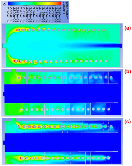
Figure 11.
Temperature contour over a plane in the cold loop of the HEXs for a 1.5 lpm flow rate at the hot loop and 2 lpm at the cold loop: (a) conventional HEX, (b) spiral fin-integrated HEX, (c) porous spiral fin-integrated HEX.
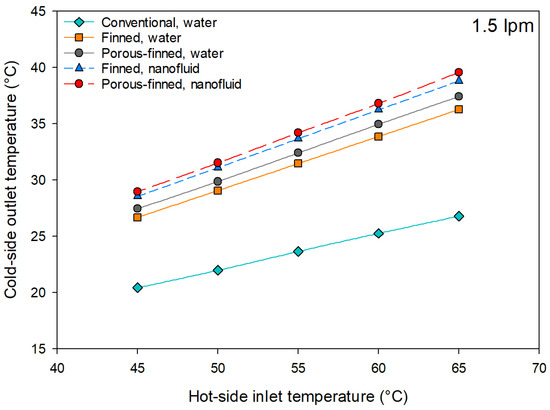
Figure 12.
Outflow temperature of cold loop of three investigated heat exchangers via hot side’s temperature.
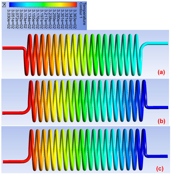
Figure 13.
Temperature contour over the coil of the HEXs for a 1.5 lpm flow rate at the hot loop and 2 lpm at the cold loop: (a) conventional HEX, (b) spiral fin-integrated HEX, (c) porous spiral fin-integrated HEX.
The main cause for the improvement of the heat exchange rate in the modified HEXs is fluid flow regulation by utilizing additional internal tube and spiral fins. Figure 14 illustrates velocity contour over a plane for the cold loop of the HEXs for conventional SHCHEX, spiral fin-integrated SHCHEX, and porous spiral fin-integrated SHCHEX. Cold water generally goes through the HEX’s center, where its contact with the helical tube is low, as shown in Figure 14a. However, cold water flows over the coiled tube and spiral fins in the modified cases as shown in Figure 14b,c. It could be said that utilizing additional tube and spiral fin integration changed the flow characteristics in the cold loop of the SHCHEX and lead to an increase in heat transfer. It may be helpful to illustrate the streamline inside the studied SHCHEXs in order to assess the flow behavior. Figure 15 presents the streamline in the cold loop of the conventional SHCHEX, spiral fin-integrated SHCHEX, and porous spiral fin-integrated SHCHEX. Also, the enlarged view of the streamline for the spiral fin-integrated SHCHEX and porous spiral fin-integrated SHCHEX are presented in Figure 15 to better show the flow behavior. The streamline for the three SHCHEXs obviously represents the flow behavior inside the cold loop and the effect of using nonporous and porous spiral fin integration. Using an additional internal tube and integrating nonporous/porous spiral fins have an important effect over the fluid flow and creation of turbulence flow. Integrating nonporous spiral fins led to the creation of the swirl effect (Figure 15b) and distributed fluid flows over the helically coiled tube which means more heat exchange. In other words, the performance of the SHCHEX improved by creating a swirl flow in line with the helical coil and producing turbulent flow. The streamline for the porous spiral fin-integrated SHCHEX presented a different behavior compared to the nonporous spiral fin-integrated SHCHEX. A portion of flowing fluid passes through the porous spiral fins led to a different flow behavior compared to the nonporous type.
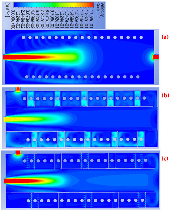
Figure 14.
Velocity contour over a plane for the cold loop of the HEX for a 2 lpm flow rate: (a) conventional HEX, (b) spiral fin-integrated HEX, (c) porous spiral fin-integrated HEX.
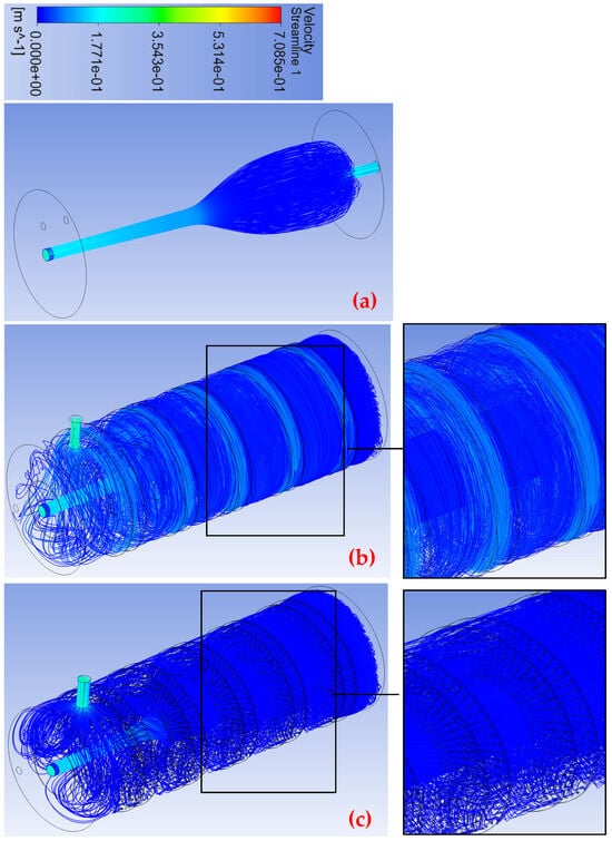
Figure 15.
Streamline in the cold loop of the HEX for a 2 lpm flow rate: (a) conventional HEX, (b) spiral fin-integrated HEX, (c) porous spiral fins integrated HEX.
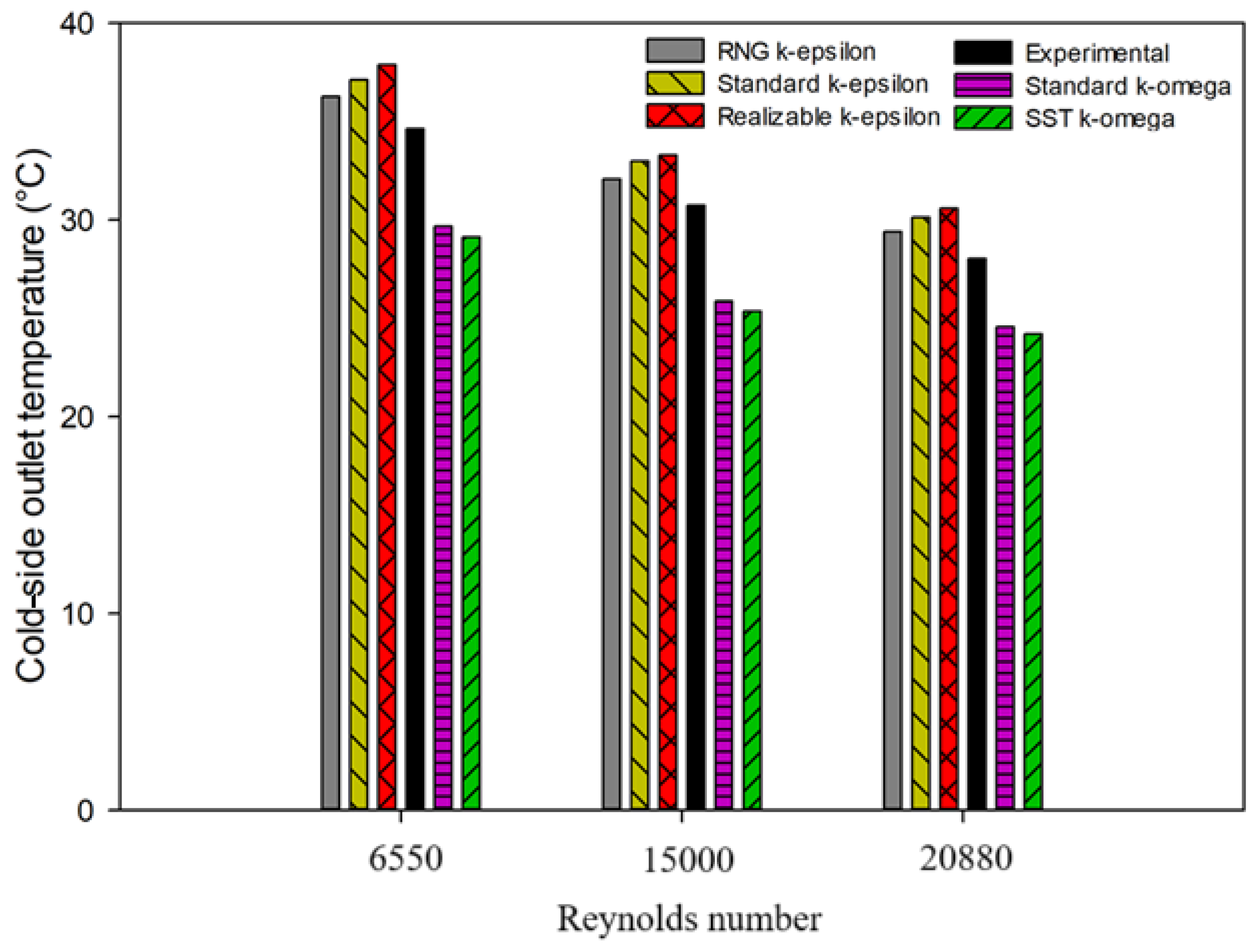
As previously stated, various turbulence models were examined in the numerical analysis section, and was chosen since it gave numerical findings that were most close to the experimental one. Figure 16 represents the obtained outlet temperature in the cold loop of the HEX by applying various turbulence models. As clearly shown in Figure 16, the achieved exit temperature of the cold loop applying as the model is the closest numerical outcome to the experimentally achieved exit temperature.
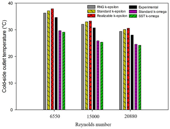
Figure 16.
Outlet temperature in the cold loop of the HEX by applying various turbulence models.
3.2. Experimental Results
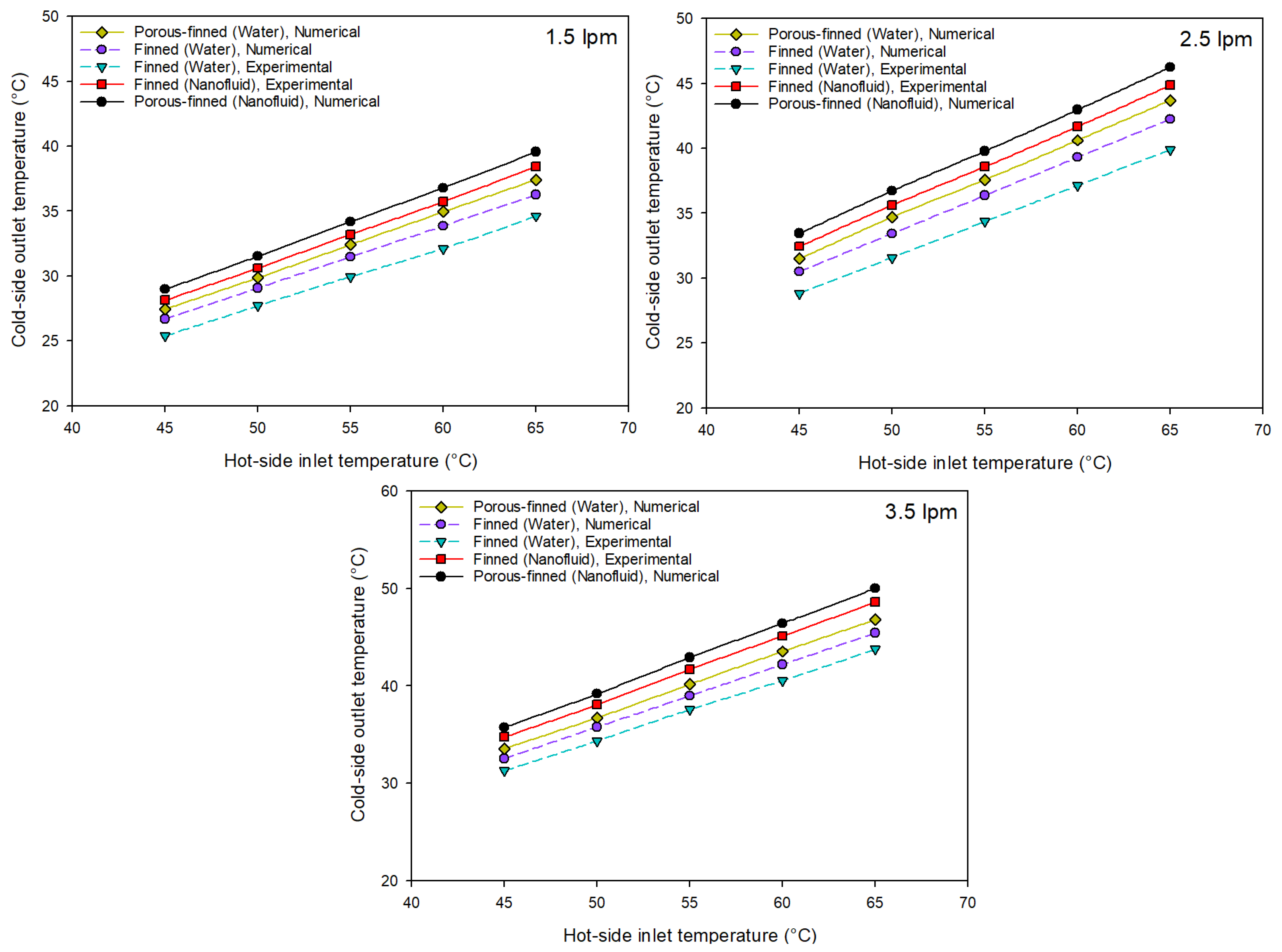
In the experimental part of the current research, the nonporous spiral fin-integrated SHCHEX has been fabricated and experimentally tested by utilizing deionized water and the MnFe2O4-ZnFe2O4/water-magnetic-hybrid NF. In this study, analyses of the SHCHEXs have been conducted in the Reynolds numbers between 6650 and 20,880. Figure 17 illustrates changes in the cold side’s outflow temperature based on the hot side’s temperature under various conditions including experimental results utilizing deionized water, experimental results utilizing the MnFe2O4-ZnFe2O4/water NF as the working medium in the hot loop, and simulation results utilizing deionized water and NF for nonporous spiral-finned and porous spiral-finned SHCHEXs. The maximum exit temperature achieved by porous spiral-finned SHCHEX using MnFe2O4-ZnFe2O4/water NF as shown in Figure 17. Additionally, comparing experimentally and numerically achieved findings for nonporous spiral fin integrated SHCHEX illustrates the reliability of the developed model. Mean variation between the experimentally obtained exit temperature of the SHCHEX and numerically achieved one is 3.9%. CFD simulation outcomes indicated that integrating porous-type spiral fins improved the outflow temperature of the cold loop of the SHCHEX as mean of 4.5% when compared to the nonporous spiral fins integrated SHCHEX. Additionally, experimentally obtained outcomes exhibited the important impact of utilizing the MnFe2O4-ZnFe2O4/water magnetic NF on heat exchange in the SHCHEX, as presented in Figure 17. Experimental findings illustrated that the MnFe2O4-ZnFe2O4/water NF usage in the SHCHEX raised the exit temperature of the cold loop by a mean of 10.8%. As seen in Figure 17, the highest exit temperature values of the cold loop are obtained for the porous spiral fin-integrated SHCHEX system with the MnFe2O4-ZnFe2O4/water magnetic NF as the working fluid. In other words, simultaneous utilization of porous spiral fins and the MnFe2O4-ZnFe2O4/water magnetic NF had the highest effect on the performance improvement of the SHCHEX. Moreover, the interaction between the nanoparticles and the secondary flow motion is an important factor influencing heat transfer. In helically coiled heat exchangers, the curvature induces secondary swirling flows which enhance radial mixing. The suspended MnFe2O4-ZnFe2O4 nanoparticles, due to their magnetic responsiveness and Brownian motion, interact with these vortices and intensify local turbulence. This results in the disruption of thermal boundary layers and promotes enhanced convective heat transfer, particularly near the tube walls.
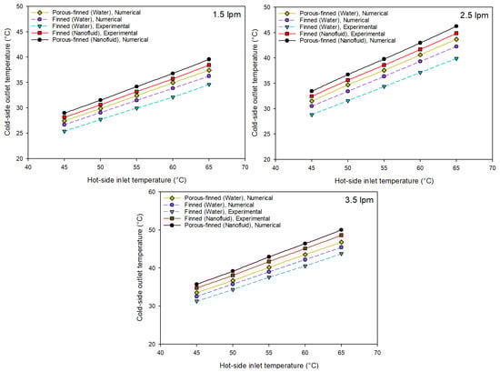
Figure 17.
Changes in the cold side’s outflow temperature based on the hot side’s temperature under various conditions.
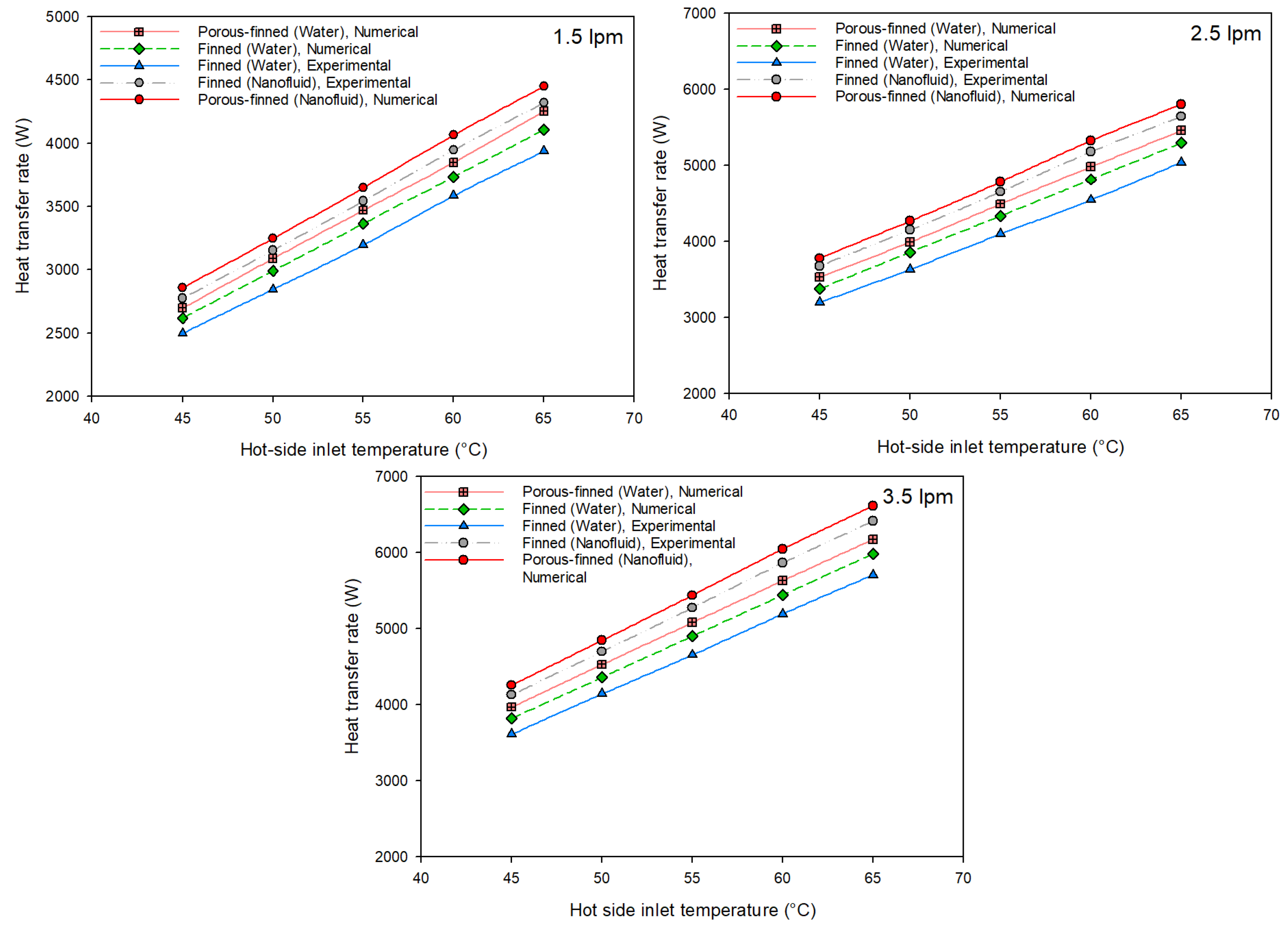
Changes in the rate of heat transfer based on the temperature of the hot side in various situations for the SHCHEX is illustrated in Figure 18. As the hot side’s inflow temperature and flow rate increase, the SHCHEX’s heat transfer rate also rises, as presented in Figure 18. Analyzing Figure 18 showed that the highest heat transfer was recorded for the porous spiral fin-integrated SHCHEX by using the MnFe2O4-ZnFe2O4/water magnetic NF as the working fluid. For the case of the nonporous spiral fin-integrated SHCHEX with deionized water as the working medium, the mean variation between the experimentally obtained transferred heat and the numerically achieved one was 5.1%. According to the CFD simulation results, adding porous spiral fins improved the energy transfer in the SHCHEX to a mean of 3.7% when compared to the nonporous spiral one. Experimental findings indicated that using the MnFe2O4-ZnFe2O4/water magnetic NF as the working medium in the SHCHEX significantly raised the transferred heat compared to the deionized water as seen in Figure 18. Utilizing the MnFe2O4-ZnFe2O4/water magnetic NF in the hot loop of the SHCHEX raised the transferred heat by a mean of 13.3% according to the experimental findings. The hybrid nanofluid exhibited higher turbulent kinetic energy values and stronger Reynolds stress magnitudes in comparison with the base fluid, indicating intensified turbulence activity. This turbulence augmentation enhances the mixing of thermal boundary layers, promoting more effective heat transfer. The influence of magnetic forces on nanoparticle alignment and local eddy formation further contributes to this enhancement.
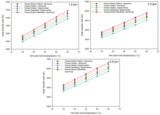
Figure 18.
Changes in the rate of heat transfer based on the temperature of the hot side in various situations.
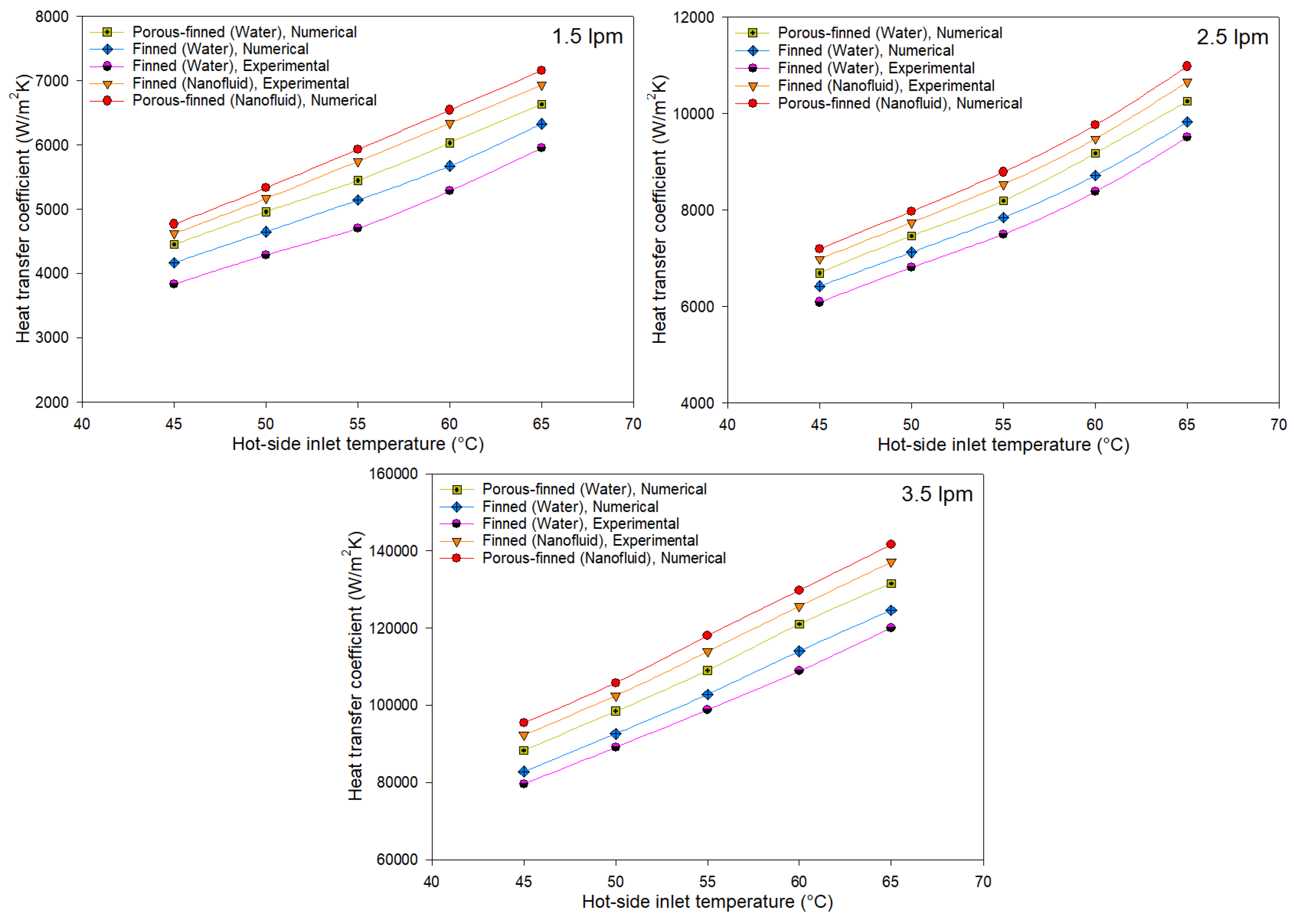
Figure 19 represents variation in the hot side’s heat transfer coefficient based on the temperature for various situations. Figure 19 shows that using spiral fins, increasing flow velocity, and rising inlet temperature are the primary factors that improved the heat transfer coefficient. In the case of the nonporous spiral fin-integrated SHCHEX, the average deviation among the numerically and experimentally achieved heat transfer coefficient was determined as 5.3%. CFD simulation results indicated that using porous-type spiral fins led to a mean increment of 5.5% in the heat transfer coefficient of the SHCHEX when compared to nonporous spiral fins. Additionally, experimental outcomes clearly illustrated the crucial impact of utilizing MnFe2O4-ZnFe2O4/water magnetic nanofluid on the heat transfer coefficient as shown in Figure 19. According to experimentally obtained heat transfer coefficient values, using the MnFe2O4-ZnFe2O4/water-hybrid magnetic NF in the hot loop of the SHCHEX improved the heat transfer coefficient of the HEX by an average ratio of 16.2%.
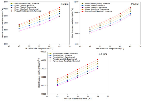
Figure 19.
Variation in the hot side’s heat transfer coefficient based on temperature for various situations.
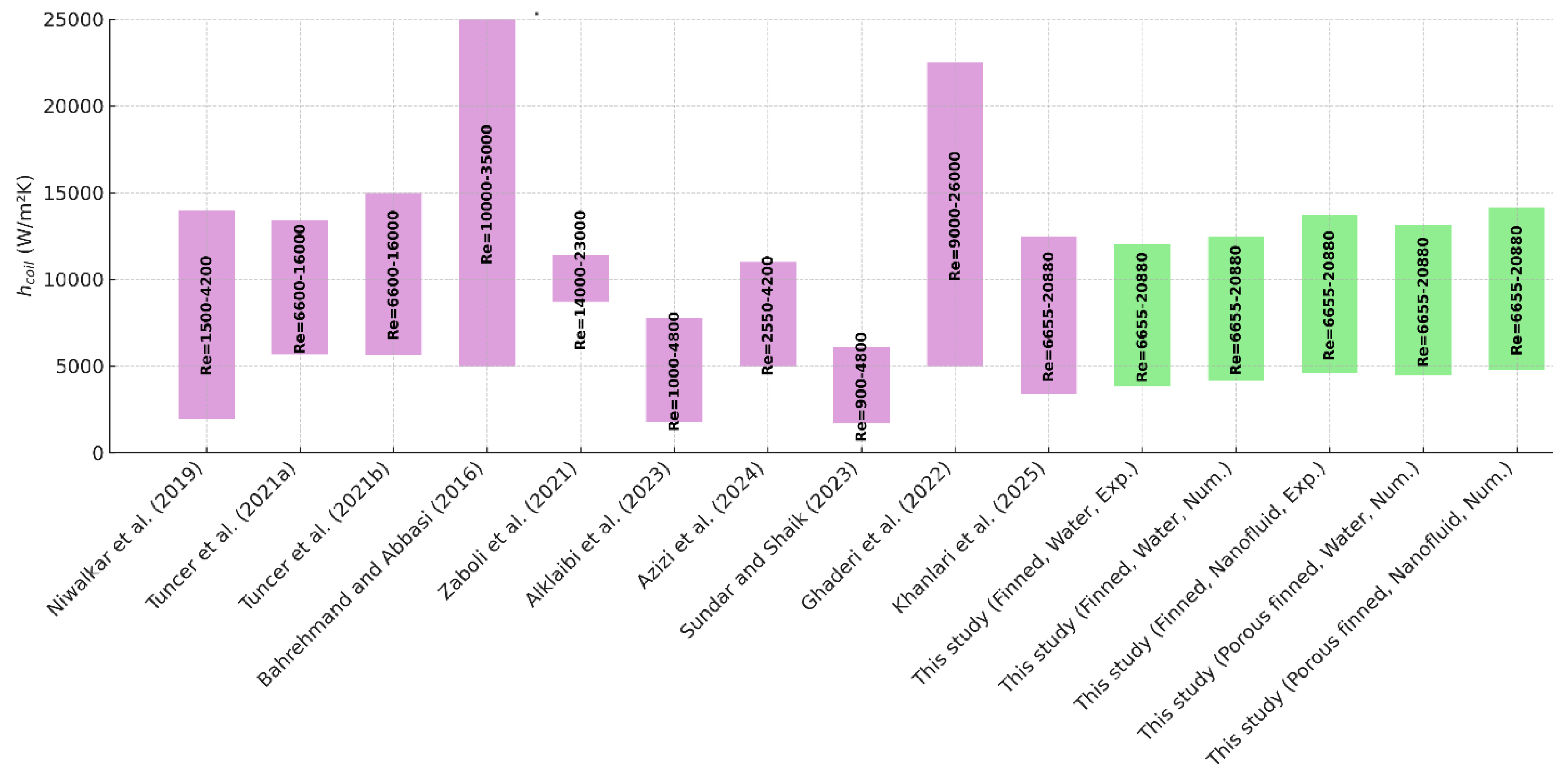
The heat transfer coefficient recorded in the current work compared to related similar studies in the literature that analyzed different SHCHEXs and are given in Figure 20. In this figure, the range of the Reynolds number and the achieved heat transfer coefficient in this work and other studies are presented. Comparing the achieved heat transfer coefficient values in the current work and related works, which investigated different SHCHEXs, represented a good agreement. It must be indicated that the Reynolds is the most crucial factor affecting the heat transfer coefficient according to the experimental results of the investigated studies.
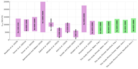
Figure 20.
Comparison among the heat transfer coefficient obtained in the current work and related similar studies in the literature [63,64,65,66,67,68,69,70,71,72].
Table 3 shows a comprehensive comparison between the results of this work and similar studies that analyzed related SHCHEXs. In this table, the impact of the applied modification on the behavior of the analyzed SHCHEX is given separately. In Table 3, related studies which analyzed SHCHEXs with similar geometrical characteristics were provided to be able to conduct a good comparison between them. But, it must be noted that it is difficult to find SHCHEXs with identical dimensions and same experimental conditions. A comparison between the findings of the current work and similar studies exhibited a good accordance between them. In the current work, a prototype of a novel SHCHEX with spiral-type fin integration was designed and analyzed both numerically and experimentally. The overall results of this study showed that the applied modifications were successful in improving the SHCHEX’s thermal performance. Also, the MnFe2O4-ZnFe2O4/water-hybrid magnetic NF utilization led to more enhancements in the heat exchange rate in the developed SHCHEX.
Table 3.
A comprehensive comparison between the results of this work and similar studies that analyzed related SHCHEXs.
4. Conclusions
The impact of a novel SHCHEX design on the HEX’s thermal behavior has been examined both experimentally and numerically in this study. The CFD method has been applied in order simulate flow and thermal behavior in the designed new SHCHEX and to specify the impact of using NF, porous spiral fins, and nonporous spiral fins on the thermal characteristics of the HEX. Then, a SHCHEX with spiral fins and an additional internal tube has been manufactured regarding to the CFD simulation findings and experimentally tested at various conditions. Also, MnFe2O4-ZnFe2O4/water magnetic NF has been experimented in the hot loop of the SHCHEX and compared with deionized water. General outcomes of the current work are listed below:
- The overall results of this study showed that the applied modifications were successful in improving the SHCHEX’s thermal performance. Controlling the flow on the cold side and directing it over the helically coiled tube are the main factors contributing to the new design’s improved heat transfer;
- There was good agreement between experimental results and CFD simulation outcomes. The mean variation between the experimentally obtained exit temperature of the SHCHEX and numerically achieved one was 3.9%.
- Utilizing the MnFe2O4-ZnFe2O4/water-hybrid magnetic NF in the hot loop of the SHCHEX raised the transferred heat, on average, 13.3% according to the experimental findings;
- According to experimentally obtained heat transfer coefficient values, using the MnFe2O4-ZnFe2O4/water-hybrid magnetic NF in the hot loop of the SHCHEX improved the heat transfer coefficient of the HEX by an average ratio of 16.2%.
The study’s overall findings showed that the use of the MnFe2O4-ZnFe2O4/water-hybrid magnetic NF and new modifications including spiral fin integration had significant effects on heat transfer in the HEX. In further research, different types of NFs can be tested in the developed SHCHEX in order to determine the impact of other types of NFs on the thermal behavior of the system.
Author Contributions
A.Y.B.: Investigation, Data curation, Writing—Original Draft, Writing—Reviewing and Editing. A.K.: Conceptualization, Methodology, Investigation, Data curation, Writing—Original Draft, Writing—Reviewing and Editing. A.D.T.: Conceptualization, Methodology, Investigation, Data curation, Writing—Original Draft, Writing—Reviewing and Editing. A.S.: Writing—Original Draft, Writing—Reviewing and Editing. H.İ.V.: Conceptualization, Methodology, Investigation, Data curation, Writing—Original Draft. K.V.: Conceptualization, Methodology, Investigation, Supervision, Data curation, Writing—Original Draft, Writing—Reviewing and Editing. All authors have read and agreed to the published version of the manuscript.
Funding
The authors declare that this study received funding from TÜBİTAK. The funder was not involved in the study design, collection, analysis, interpretation of data, the writing of this article, or the decision to submit it for publication.
Data Availability Statement
The original contributions presented in this study are included in the article. Further inquiries can be directed to the corresponding author.
Acknowledgments
The present research was supported by the Scientific and Technological Research Council of Turkey (Project no: 1059B192302392). We are indebted to TÜBİTAK for its financial support.
Conflicts of Interest
Author Azim Doğuş Tuncer was employed by the company Cooling Photonics S.L. Azim Doğuş Tuncer states that in this paper there is nothing that may be considered to be a conflict of interest. The remaining authors declare that the research was conducted in the absence of any commercial or financial relationships that could be construed as a potential conflict of interest.
Nomenclature
| heat transfer surface area (m2) | |
| heat capacity (kJ/kg.K) | |
| helically coiled tube diameter (m) | |
| interior diameter of helically coiled tube (m) | |
| coil diameter (m) | |
| shell diameter (m) | |
| hydraulic diameter | |
| Dean number | |
| total energy (J) | |
| height | |
| heat transfer coefficient (W/m2.K) | |
| conductivity (W/m.K) | |
| mass flow rate (kg/s) | |
| Nusselt number | |
| pressure (Pa) | |
| Reynolds number | |
| temperature (K) | |
| rate of heat transfer (W) | |
| overall heat transfer coefficient (W/m2.K) | |
| velocity (m/s) | |
| overall velocity vector (m/s) | |
| the uncertainties in the independent variables | |
| the overall uncertainty (%) | |
| Greek letters | |
| logarithmic mean temperature difference (K) | |
| dynamic viscosity (Pa.s) | |
| density (kg/m3) | |
| Subcripts | |
| c | coil |
| in | inlet |
| it | inner tube |
| out | outlet |
| t | tube |
References
- Maghrabie, H.M.; Attalla, M.; Mohsen, A.A. Performance of a shell and helically coiled tube heat exchanger with variable inclination angle: Experimental study and sensitivity analysis. Int. J. Therm. Sci. 2021, 164, 106869. [Google Scholar] [CrossRef]
- Dizaji, H.S.; Jafarmadar, S.; Hashemian, M. The effect of flow, thermodynamic and geometrical characteristics on exergy loss in shell and coiled tube heat exchangers. Energy 2015, 91, 678–684. [Google Scholar] [CrossRef]
- Maghrabie, H.M.; Attalla, M.; Mohsen, A.A. Performance assessment of a shell and helically coiled tube heat exchanger with variable orientations utilizing different nanofluids. Appl. Therm. Eng. 2021, 182, 116013. [Google Scholar] [CrossRef]
- Andrzejczyk, R.; Muszynski, T. An experimental investigation on the effect of new continuous core-baffle geometry on the mixed convection heat transfer in shell and coil heat exchanger. Appl. Therm. Eng. 2018, 136, 237–251. [Google Scholar] [CrossRef]
- Jamshidi, N.; Farhadi, M.; Ganji, D.D.; Sedighi, K. Experimental analysis of heat transfer enhancement in shell and helical tube heat exchangers. Appl. Therm. Eng. 2013, 51, 644–652. [Google Scholar] [CrossRef]
- Khorasani, S.; Dadvand, A. Effect of air bubble injection on the performance of a horizontal helical shell and coiled tube heat exchanger: An experimental study. Appl. Therm. Eng. 2017, 111, 676–683. [Google Scholar] [CrossRef]
- Khorasani, S.; Moosavi, A.; Dadvand, A.; Hashemian, M. A comprehensive second law analysis of coil side air injection in the shell and coiled tube heat exchanger: An experimental study. Appl. Therm. Eng. 2019, 150, 80–87. [Google Scholar] [CrossRef]
- Fuxi, S.; Sina, N.; Ahmadi, A.; Malekshah, E.H.; Mahmoud, M.Z.; Aybar, H.Ş.H. Effect of different pitches on the 3D helically coiled shell and tube heat exchanger filled with a hybrid nanofluid: Numerical study and artificial neural network modeling. Eng. Anal. Bound. Elem. 2022, 143, 755–768. [Google Scholar] [CrossRef]
- Barzegarian, R.; Aloueyan, A.; Yousefi, T. Thermal performance augmentation using water based Al2O3-gamma nanofluid in a horizontal shell and tube heat exchanger under forced circulation. Int. Commun. Heat Mass Transf. 2017, 86, 52–59. [Google Scholar] [CrossRef]
- Kuruneru, S.T.W.; Vafai, K.; Sauret, E.; Gu, Y. Application of porous metal foam heat exchangers and the implications of particulate fouling for energy-intensive industries. Chem. Eng. Sci. 2020, 228, 115968. [Google Scholar] [CrossRef]
- Mahjoob, S.; Vafai, K.K. A synthesis of fluid and thermal transport models for metal foam heat exchangers. Int. J. Heat Mass Transf. 2008, 51, 3701–3711. [Google Scholar] [CrossRef]
- Yüksel, C.; Öztürk, M.; Çiftçi, E.E. Analysis of a novel V-grooved double pass photovoltaic thermal solar dryer including thermal energy storage. Appl. Therm. Eng. 2024, 236, 121697. [Google Scholar] [CrossRef]
- Kang, Y.T.; Christensen, R.N.; Vafai, K. Analysis of absorption process in a smooth-tube heat exchanger with a porous medium. Heat Transf. Eng. 1994, 15, 42–55. [Google Scholar] [CrossRef]
- Chen, X.; Tavakkoli, F.; Vafai, K. Analysis and characterization of metal foam-filled double-pipe heat exchangers. Numer. Heat Transf. Part A Appl. 2015, 68, 1031–1049. [Google Scholar] [CrossRef]
- Öztürk, M.; Yüksel, C.; Çiftçi, E. Energy, exergy and sustainability analysis of a photovoltaic-thermal solar system with nano-enhancement and thermal energy storage integration. Process Saf. Environ. Prot. 2024, 187, 593–604. [Google Scholar] [CrossRef]
- Zing, C.; Mahjoob, S.; Vafai, K. Analysis of porous filled heat exchangers for electronic cooling. Int. J. Heat Mass Transf. 2019, 133, 268–276. [Google Scholar] [CrossRef]
- Al-Sammarraie, A.T.; Vafai, K. Thermal–hydraulic performance analysis of a convergent double pipe heat exchanger. J. Heat Transf. 2019, 141, 051001. [Google Scholar] [CrossRef]
- Güngör, A.; Khanlari, A.; Sözen, A.; Variyenli, H.İ. Numerical and experimental study on thermal performance of a novel shell and helically coiled heat exchanger design with integrated rings and discs. Int. J. Therm. Sci. 2022, 182, 107781. [Google Scholar] [CrossRef]
- Solanki, A.K.; Kumar, R. Two-phase flow condensation heat transfer characteristic of R-600a inside the horizontal smooth and dimpled helical coiled tube in shell type heat exchanger. Int. J. Refrig. 2019, 107, 155–164. [Google Scholar] [CrossRef]
- Solanki, A.K.; Kumar, R. Condensation of R-134a inside dimpled helically coiled tube-in-shell type heat exchanger. Appl. Therm. Eng. 2018, 129, 535–548. [Google Scholar] [CrossRef]
- Zolfagharnasab, M.H.; Pedram, M.Z.; Hoseinzadeh, S.; Vafai, K. Application of porous-embedded shell and tube heat exchangers for the waste heat recovery systems. Appl. Therm. Eng. 2022, 211, 118452. [Google Scholar] [CrossRef]
- Andrzejczyk, R.; Muszynski, T. Thermodynamic and geometrical characteristics of mixed convection heat transfer in the shell and coil tube heat exchanger with baffles. Appl. Therm. Eng. 2017, 121, 115–125. [Google Scholar] [CrossRef]
- Afshari, F. Experimental and numerical investigation on thermoelectric coolers for comparing air-to-water to air-to-air refrigerators. J. Therm. Anal. Calorim. 2021, 144, 855–868. [Google Scholar] [CrossRef]
- Afshari, F.; Zavaragh, H.G.; Di Nicola, G. Numerical analysis of ball-type turbulators in tube heat exchangers with computational fluid dynamic simulations. Int. J. Environ. Sci. Technol. 2019, 16, 3771–3780. [Google Scholar] [CrossRef]
- Çiftçi, E. Simulation of nucleate pool boiling heat transfer characteristics of the aqueous kaolin and bauxite nanofluids. Heat Transf. Res. 2021, 52, 77–92. [Google Scholar] [CrossRef]
- Zhang, C.; Wang, D.; Xiang, S.; Han, Y.; Peng, X. Numerical investigation of heat transfer and pressure drop in helically coiled tube with spherical corrugation. Int. J. Heat Mass Transf. 2017, 113, 332–341. [Google Scholar] [CrossRef]
- Abu-Hamdeh, N.H.; Bantan, R.A.R.; Tlili, I. Analysis of the thermal and hydraulic performance of the sector-by-sector helically coiled tube heat exchangers as a new type of heat exchangers. Int. J. Therm. Sci. 2020, 150, 106229. [Google Scholar] [CrossRef]
- Shafahi, M.; Bianco, V.; Vafai, K.; Manca, O. Thermal performance of flat-shaped heat pipes using nanofluids. Int. J. Heat Mass transfer 2010, 53, 1438–1445. [Google Scholar] [CrossRef]
- Gürü, M.; Sözen, A.; Karakaya, U.; Çiftçi, E. Influences of bentonite-deionized water nanofluid utilization at different concentrations on heat pipe performance: An experimental study. Appl. Therm. Eng. 2019, 148, 632–640. [Google Scholar] [CrossRef]
- Khanafer, K.; Vafai, K. Applications of nanofluids in porous medium: A critical review. J. Therm. Anal. Calorim. 2019, 135, 1479–1492. [Google Scholar] [CrossRef]
- Çiftçi, E. Distilled water-based AlN+ ZnO binary hybrid nanofluid utilization in a heat pipe and investigation of its effects on performance. Int. J. Thermophys. 2021, 42, 38. [Google Scholar] [CrossRef]
- Gülmüş, B.; Muratçobanoğlu, B.; Mandev, E.; Afshari, F. Experimental and numerical investigation of flow and thermal characteristics of aluminum block exchanger using surface-modified and recycled nanofluids. Int. J. Numer. Methods Heat Fluid Flow 2023, 33, 2685–2709. [Google Scholar] [CrossRef]
- Muratçobanoğlu, B.; Afshari, F. Effects of nanoparticle size on properties of nanofluid and heat transfer enhancement in spiral exchanger using turbulators. Nanosci. Technol. Int. J. 2023, 14, 65–90. [Google Scholar] [CrossRef]
- Afshari, F.; SÖZEN, A.; Khanlari, A.; Tuncer, A.D. Heat transfer enhancement of finned shell and tube heat exchanger using Fe2O3/water nanofluid. J. Cent. South Univ. 2021, 28, 3297–3309. [Google Scholar] [CrossRef]
- Elmnefi, M.; Abdullah, R. Experimental study of heat transfer enhancement using Al2O3/water and TiO2/water nanofluids in a shell-and-tube heat exchanger. Heat Transf. Res. 2021, 52, 15–37. [Google Scholar] [CrossRef]
- Afshari, F.; Muratçobanoğlu, B. Thermal analysis of Fe3O4/water nanofluid in spiral and serpentine mini channels by using experimental and theoretical models. Int. J. Environ. Sci. Technol. 2023, 20, 2037–2052. [Google Scholar] [CrossRef]
- Naik, B.A.K.; Vinod, A.V. Heat transfer enhancement using non-Newtonian nanofluids in a shell and helical coil heat exchanger. Exp. Therm. Fluid Sci. 2018, 90, 132–142. [Google Scholar] [CrossRef]
- Güngör, A.; Sözen, A.; Khanlari, A. Numerical investigation of thermal performance enhancement potential of using Al2O3-TiO2/water hybrid nanofluid in shell and helically coiled heat exchangers. Heat Transf. Res. 2022, 53, 37–54. [Google Scholar] [CrossRef]
- Srinivas, T.; Vinod, A.V. Heat transfer intensification in a shell and helical coil heat exchanger using water-based nanofluids. Chem. Eng. Process. Process Intensif. 2016, 102, 1–8. [Google Scholar] [CrossRef]
- Behera, M.; Nayak, J.; Bal, S. Heat transfer analysis of CuO-ZnO/water hybrid nanofluid in a Shell and tube heat exchanger with various tube shapes. Int. J. Thermofluids 2024, 24, 100972. [Google Scholar] [CrossRef]
- Gaur, S.K.; Sahoo, R.R.; Sarkar, J. Numerical investigation on assessing the influence of diverse-shaped hybrid nanofluids on thermal performance of triple tube heat exchanger. Powder Technol. 2024, 439, 119690. [Google Scholar] [CrossRef]
- Said, Z.; Rahman, S.; Sharma, P.; Hachicha, A.A.; Issa, S. Performance characterization of a solar-powered shell and tube heat exchanger utilizing MWCNTs/water-based nanofluids: An experimental, numerical, and artificial intelligence approach. Appl. Therm. Eng. 2022, 212, 118633. [Google Scholar] [CrossRef]
- Behrozifard, A.; Goshayeshi, H.R.; Zahmatkesh, I.; Chaer, I.; Salahshour, S.; Toghraie, D. Experimental optimization of the performance of a plate heat exchanger with Graphene oxide/water and Al2O3/water nanofluids. Case Stud. Therm. Eng. 2024, 59, 104525. [Google Scholar] [CrossRef]
- Sheikholeslami, M.; Jafaryar, M.; Said, Z.; Alsabery, A.I.; Babazadeh, H.; Shafee, A. Modification for helical turbulator to augment heat transfer behavior of nanomaterial via numerical approach. Appl. Therm. Eng. 2021, 182, 115935. [Google Scholar] [CrossRef]
- Chandran, S.S.; Roy, K.R.; Barik, D.; Arun, M.; Pullagura, G.; Rout, S.K.; Dennison, M.S. Empirical Correlation to Analyze Performance of Shell and Tube Heat Exchanger Using TiO2 Nanofluid-DI Water in Solar Water Heater. Case Stud. Therm. Eng. 2024, 60, 104652. [Google Scholar] [CrossRef]
- Kumar, N.; Sonawane, S.S. Experimental study of Fe2O3/water and Fe2O3/ethylene glycol nanofluid heat transfer enhancement in a shell and tube heat exchanger. Int. Commun. Heat Mass Transf. 2016, 78, 277–284. [Google Scholar] [CrossRef]
- Bhanvase, B.A.; Sayankar, S.D.; Kapre, A.; Fule, P.J.; Sonawane, S.H. Experimental investigation on intensified convective heat transfer coefficient of water based PANI nanofluid in vertical helical coiled heat exchanger. Appl. Therm. Eng. 2018, 128, 134–140. [Google Scholar] [CrossRef]
- Huminic, G.; Huminic, A. Hybrid nanofluids for heat transfer applications–a state-of-the-art review. Int. J. Heat Mass Transf. 2018, 125, 82–103. [Google Scholar] [CrossRef]
- Huminic, G.; Huminic, A.; Dumitrache, F.; Fleacă, C.; Morjan, I. Study of the thermal conductivity of hybrid nanofluids: Recent research and experimental study. Powder Technol. 2020, 367, 347–357. [Google Scholar] [CrossRef]
- Huminic, G.; Huminic, A. A numerical approach on hybrid nanofluid behavior in laminar duct flow with various cross sections. J. Therm. Anal. Calorim. 2020, 140, 2097–2110. [Google Scholar] [CrossRef]
- Karaaslan, I.; Menlik, T. Numerical study of a photovoltaic thermal (PV/T) system using mono and hybrid nanofluid. Sol. Energy 2021, 224, 1260–1270. [Google Scholar] [CrossRef]
- Tuncer, A.D.; Khanlari, A.; Sözen, A.; Gürbüz, E.Y.; Variyenli, H.I. Upgrading the performance of shell and helically coiled heat exchangers with new flow path by using TiO2/water and CuO-TiO2/water nanofluids. Int. J. Therm. Sci. 2023, 183, 107831. [Google Scholar] [CrossRef]
- Afshari, F.; Ceviz, M.A.; Mandev, E.; Yıldız, F. Effect of heat exchanger base thickness and cooling fan on cooling performance of Air-To-Air thermoelectric refrigerator; experimental and numerical study. Sustain. Energy Technol. Assess. 2022, 52, 102178. [Google Scholar] [CrossRef]
- Afshari, F.; Mandev, E.; Muratçobanoğlu, B.; Yetim, A.F.; Ceviz, M.A. Experimental and numerical study on a novel fanless air-to-air solar thermoelectric refrigerator equipped with boosted heat exchanger. Renew. Energy 2023, 207, 253–265. [Google Scholar] [CrossRef]
- Ansys. ANSYS Fluent Theory Guide; ANSYS Inc.: Canonsburg, PA, USA, 2017. [Google Scholar]
- Khanlari, A. The Effect of utilizing Al2O3-SiO2/deionized water hybrid nanofluid in a tube-type heat exchanger. Heat Transf. Res. 2020, 51, 991–1005. [Google Scholar] [CrossRef]
- Ramesh, R.; Murugesan, S.N.; Narendran, C.; Saravanan, R. Experimental investigations on shell and helical coil solution heat exchanger in NH3-H2O vapour absorption refrigeration system (VAR). Int. Commun. Heat Mass Transf. 2017, 87, 6–13. [Google Scholar] [CrossRef]
- Hardik, B.K.; Baburajan, P.K.; Prabhu, S.V. Local heat transfer coefficient in helical coils with single phase flow. Int. J. Heat Mass transfer 2015, 89, 522–538. [Google Scholar] [CrossRef]
- Tuncer, D.; Khanlari, A. Analyzing the effect of flooring material type on the performance of an active greenhouse dryer. Therm. Sci. Eng. Prog. 2024, 48, 102371. [Google Scholar] [CrossRef]
- Khanlari, A.; Aydın, D.Y.; Sözen, A.; Gürü, M.; Variyenli, H.İ. Investigation of the influences of kaolin-deionized water nanofluid on the thermal behavior of concentric type heat exchanger. Heat Mass Transf. 2020, 56, 1453–1462. [Google Scholar] [CrossRef]
- Elshazly, K.M.; Sakr, R.Y.; Ali, R.K.; Salem, M.R. Effect of γ-Al2O3/water nanofluid on the thermal performance of shell and coil heat exchanger with different coil torsions. Heat Mass Transf. 2017, 53, 1893–1903. [Google Scholar] [CrossRef]
- Panahi, D.; Zamzamian, K. Heat transfer enhancement of shell-and-coiled tube heat exchanger utilizing helical wire turbulator. Appl. Therm. Eng. 2017, 115, 607–615. [Google Scholar] [CrossRef]
- Niwalkar, A.F.; Kshirsagar, J.M.; Kulkarni, K. Experimental investigation of heat transfer enhancement in shell and helically coiled tube heat exchanger using SiO2/water nanofluids. Mater. Today: Proc. 2019, 18, 947–962. [Google Scholar] [CrossRef]
- Tuncer, A.D.; Sözen, A.; Khanlari, A.; Gürbüz, E.Y.; Variyenli, H.İ. Analysis of thermal performance of an improved shell and helically coiled heat exchanger. Appl. Therm. Eng. 2021, 184, 116272. [Google Scholar] [CrossRef]
- Tuncer, A.D.; Sözen, A.; Khanlari, A.; Gürbüz, E.Y.; Variyenli, H.İ. Upgrading the performance of a new shell and helically coiled heat exchanger by using longitudinal fins. Appl. Therm. Eng. 2021, 191, 116876. [Google Scholar] [CrossRef]
- Bahrehmand, S.; Abbassi, A. Heat transfer and performance analysis of nanofluid flow in helically coiled tube heat exchangers. Chem. Eng. Res. Des. 2016, 109, 628–637. [Google Scholar] [CrossRef]
- Zaboli, M.; Saedodin, S.; Ajarostaghi, S.S.M.; Nourbakhsh, M. Numerical evaluation of the heat transfer in a shell and corrugated coil tube heat exchanger with three various water-based nanofluids. Heat Transf. 2021, 50, 6043–6067. [Google Scholar] [CrossRef]
- Alklaibi, A.M.; Mouli, K.V.C.; Sundar, L.S. Experimental investigation of heat transfer and effectiveness of employing water and ethylene glycol mixture based Fe3O4 nanofluid in a shell and helical coil heat exchanger. Therm. Sci. Eng. Prog. 2023, 40, 101739. [Google Scholar] [CrossRef]
- Azizi, H.Z.; Shokri, V.; Karouei, S.H.H. Hydrothermal behaviour of hybrid nanofluid flow in a shell-and conical coil tube heat exchanger; numerical approach. Case Stud. Therm. Eng. 2024, 58, 104435. [Google Scholar] [CrossRef]
- Sundar, L.S.; Shaik, F. Heat transfer and exergy efficiency analysis of 60% water and 40% ethylene glycol mixture diamond nanofluids flow through a shell and helical coil heat exchanger. Int. J. Therm. Sci. 2023, 184, 107901. [Google Scholar] [CrossRef]
- Ghaderi, A.; Veysi, F.; Aminian, S.; Andami, Z.; Najafi, M. Experimental and Numerical Study of Thermal Efficiency of Helically Coiled Tube Heat Exchanger Using Ethylene Glycol-Distilled Water Based Fe3O4 Nanofluid. Int. J. Thermophys. 2022, 43, 118. [Google Scholar] [CrossRef]
- Khanlari, A.; Sözen, A.; Variyenli, H.İ.; Tuncer, A.D.; Vafai, K. The effect of using circular and porous circular fins on the thermal performance of a shell and helically coiled heat exchanger: A numerical and experimental study. Int. J. Therm. Sci. 2025, 214, 109894. [Google Scholar] [CrossRef]
- Barzegari, H.; Tavakoli, A.; Vahid, D.J.; Bekhradinassab, E. Experimental study of heat transfer enhancement in a helical tube heat exchanger by alumina nanofluid as current flow. Heat Mass Transf. 2019, 55, 2679–2688. [Google Scholar] [CrossRef]
- Kulkarni, H.R.; Dhanasekaran, C.; Rathnakumar, P.; Varuvel, E.G.; Sivaganesan, S.; Anantachar, M. Investigation on performance of bio synthesized copper nano fluid in helical coil and shell type heat exchanger. Mater. Today Proc. 2022, 52, 862–866. [Google Scholar] [CrossRef]


Disclaimer/Publisher’s Note: The statements, opinions and data contained in all publications are solely those of the individual author(s) and contributor(s) and not of MDPI and/or the editor(s). MDPI and/or the editor(s) disclaim responsibility for any injury to people or property resulting from any ideas, methods, instructions or products referred to in the content. |
© 2025 by the authors. Licensee MDPI, Basel, Switzerland. This article is an open access article distributed under the terms and conditions of the Creative Commons Attribution (CC BY) license (https://creativecommons.org/licenses/by/4.0/).