Abstract
This article presents a comprehensive experimental and theoretical study and substantiation of the hydraulic parameters of a prototype multi-gear pump. The proposed pump design, which features one drive gear and four driven gears, aims to address the common disadvantages of traditional gear pumps, including radial force imbalance, uneven flow, high acoustic noise, and increased fluid leakage. Tests of the prototype multi-stage pump were conducted on a specialized test stand in the “Hydraulics” workshop of “Hansa-Flex Hydraulik Almaty” LLP. Experimental analysis, supported by theoretical calculations, established the optimal operating speed range for the prototype to be between 900 and 1450 rpm, with the volumetric efficiency remaining stable between 70% and 88% when using VMGZ hydraulic oil (45 cSt). A significant deterioration in performance, including a sharp drop in volumetric efficiency to 30% and a decrease in the pressure generated, was observed at rotational speeds below 900 rpm due to an increase in internal leaks. In addition, this study examined the effect of kinematic viscosity, which revealed a 15–20% decrease in performance and power when using a fluid with lower viscosity (15 cSt) with a slight increase in noise level. This study also examines in detail the linear relationship between useful power and pressure in the system and analyzes noise characteristics under various operating conditions.
1. Introduction
To ensure a high pump’s capacity and the reliability of hydraulic systems, special attention must be paid to hydraulic pumps, especially gear pumps, which are widely used in various fields such as the chemical industry [1], petrochemical industry, mechanical engineering [2], energy [3], and aviation for pumping thick [4] and low-viscosity fluids without solid inclusions [5]. Improving the efficiency of these pumps is a key factor in improving the performance of hydraulic drives.
Gear pumps have a number of significant advantages [6]. Thanks to the precise manufacturing and standardization of components, they are easily adaptable to modern technological solutions [7]. Important characteristics include low noise and pulsation levels [8], ease of use, and the ability to operate in both directions with high accuracy [9], especially when pumping viscous fluids [10].
Modern manufacturers are actively looking for ways to improve the design of gear pumps [11] and increase their performance by applying various design and technological solutions [12].
To optimize gear pumps in terms of performance criteria, including smooth flow and specific power, active work is being performed to analyze and develop new gear profiles [13]. Uneven flow is a serious limitation for positive displacement pumps [14], since stable flow directly affects noise reduction and vibration reduction in mating systems [15].
Scientific publications indicate significant research activity in the field of gear pump studies, using various models [16], numerical simulations [17], and experimental approaches to analyze their behavior in detail from various perspectives [18].
When designing gear pumps, an important step is to conduct experiments to determine their operating characteristics.
In [19], an experiment was conducted on a gear pump manufactured in Nigeria, which can deliver approximately 4.09123 × 10⁻⁴ m3/s (24.55 L/min) of hydraulic oil, with an operating efficiency of 81.47%. In study [20], the performance of cylindrical and elliptical gear pumps at different speeds was experimentally determined. The studies showed that the elliptical gear pump demonstrates improved pressure performance (87%), especially when operating at low speeds. In [21], tests are presented on hydraulic pumps with external gear meshing, operating at 6–25 cm3/cycle, a working pressure of 250 bar, a working speed of 3000 rpm, and a hydraulic fluid temperature of 50 °C. There are also a number of studies on determining the noise characteristics of gear pumps. In addition, there are a number of works [22,23] that focus on researching noise sources in gear pumps and developing strategies to reduce them, as this is a key factor in improving the efficiency of modern hydraulic systems and expanding their scope of application.
The paper in [24] analyzes the influence of the working medium temperature and pump speed on the operating parameters of a gear pump and pump motor. The study shows that for any pump speed and working fluid temperature, there is an optimal value of the pump’s effective power at which the pump motor achieves maximum efficiency.
The study in [25] presents experimental studies of pumps to determine their thermodynamic and flow characteristics.
The study in [26] is devoted to the investigation of the operation of gear pumps and the influence of various variables on their efficiency. Here, the dependences of the performance on the head, the performance on the input power, the performance on the efficiency, and the performance on the required net positive suction head (NPSHr) are established.
Despite the wide range of existing gear pump designs in modern industry, it is known that they have a number of disadvantages [27]:
- (1)
- The presence of unbalanced radial forces arising from the pressure difference between the inlet and outlet ports. The action of radial forces leads to increased friction and wear of the gears and the inner surface of the pump housing; increased load on the bearings; and it may lead to bending of the drive gear shaft.
- (2)
- Uneven fluid delivery and high acoustic noise levels due to pressure fluctuations in the pump cavities caused by constantly changing volumes in the pump discharge cavity as a result of the teeth alternately engaging and disengaging.
- (3)
- Increased clearances during operation, causing increased leakage and, consequently, a decrease in volumetric efficiency. Fluid leaks in a gear pump are caused by overflow from the discharge chamber to the suction chamber through three main channels: through the radial clearance between the cylindrical surfaces of the gears and the bores in the housing; through the meshing zone due to tooth contact errors; and through the clearance between the end surfaces of the gears and the sealing parts.
To minimize these shortcomings, the authors developed a prototype of a multi-gear pump with one drive gear and four driven gears.
It is known from mechanics that the presence of several driven gears (satellites) around the drive gear improves dynamics, i.e., unloads the central gear support and reduces the overall dimensions, making the design compact [28]. In previous works [29,30], an FEM analysis was performed, confirming that the radial forces in such a design are balanced. Parametric optimization of the multi-gear pump parts was also performed [31].
Uniformity of the supply and a reduction in the pressure pulsations in the discharge line are achieved by varying the degree of opening of the openings for the suction and discharge of fluid in the housing and, consequently, by the time-shifted displacement of the working fluid from the chambers, which is due to the peculiarities of the gear assembly. The prototype uses the basic principle of a gear pump, where rotating gears (in your case, one drive gear and four driven gears) pump the fluid by meshing the teeth and moving the fluid volumes.
This article aims to study the hydraulic characteristics of the working fluid flow in a multi-gear pump. Particular attention is paid to establishing the patterns that determine the operation of the pump under various operating conditions, followed by the development of recommendations for its optimization and performance improvement.
The novelty of this work lies in the creation and investigation of a new prototype multi-gear pump comprising one drive gear and four driven gears. This design has been specifically developed to address the shortcomings of traditional gear pumps. The prototype aims to solve problems such as unbalanced radial forces, uneven fluid delivery, high noise levels, and increased leakage, which are inherent in traditional gear pumps.
This study confirms that in the developed multi-gear pump design, the radial forces acting on the shaft will be balanced thanks to the presence of four discharge zones and several driven gears around the drive gear.
The originality of this work lies in the fact that uniform flow and reduced pressure pulsations are achieved by varying the degree of opening of the suction and discharge ports, as well as by the time shift in the working fluid displacement from the chambers, which is a feature of the developed multi-gear pump design. The originality of this work also lies in establishing the optimal working fluid speed ranges (900–1450 rpm) for the prototype, determining the effect of fluid viscosity on its performance and noise level. This is important for the practical application of the new design, since data for such multi-gear configurations may have been lacking previously.
2. Materials and Methods
2.1. The Object of This Research
The object of this study is an innovative multi-stage pump design (Figure 1). This pump is a cutting-edge development designed to significantly improve existing performance and efficiency parameters in fluid transfer systems. The main design parameters of the experimental model of the gear pump are given below:
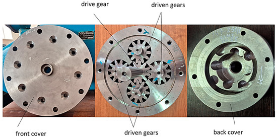
Figure 1.
Components of the prototype multi-gear pump.
- -
- Working volume V = 81 cm3;
- -
- Diameter of the pitch circle of the gear d = 55 mm;
- -
- Diameter of one suction hole dsuc = 18 mm;
- -
- Discharge hole diameter dd = 25 mm;
- -
- Overall dimensions of the pump assembly: height H = 258 mm;
- -
- Diameter of front cover D = 330 mm.
2.2. The Operation Principle of the Multi-Gear Pump
The principle of operation of the proposed multi-gear pump design is as follows (Figure 2).
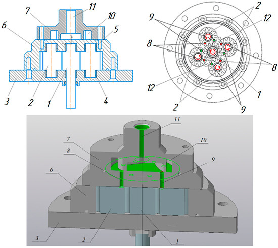
Figure 2.
Structural diagram of a multi-gear pump: 1—drive gear; 2—driven gears; 3—lower cover; 4, 5—bushings; 6—housing; 7—upper cover (collector); 8—holes for fluid intake; 9—holes for fluid injection; 10—low pressure chamber; 11—hole for fluid injection into the upper cover; 12—segment for separation of working volumes of gears.
When drive gear 1 rotates clockwise, it meshes with driven gears 2, causing them to rotate in the opposite direction (counter clockwise). The gears rotate in bronze bushings 4, 5. When the drive gear rotates clockwise, the fluid is sucked in through a side opening in upper cover (collector) 7 and then enters the pump’s working chambers through openings 8 in the pump housing. When the driven gears rotate, the fluid is transferred through the tooth cavities into the discharge cavity, where it is displaced through holes for fluid injection 9 in pump housing 6 and then combined into a common flow in upper cover (collector) 7; finally, it is displaced through the hole for fluid injection in upper cover 11 into the discharge line. The working chambers of the driven gears are separated from each other by special segments 12 made in the pump housing.
In the presented design, thanks to the four discharge zones, the radial forces acting on the shaft will be balanced. The uniformity of the supply and reduction in the pressure pulsations are achieved due to the fact that gears 1 and 2 engage and disengage with a time delay. All the pumped fluid from the working chambers flows into the manifold, where the displaced flows are combined into one. Despite its significant working volume, the pump design is quite compact.
Figure 3 shows the design of a multi-gear pump, where the area of the discharge openings is marked in red, and the area of the suction openings is marked in green when the drive gear rotates clockwise.
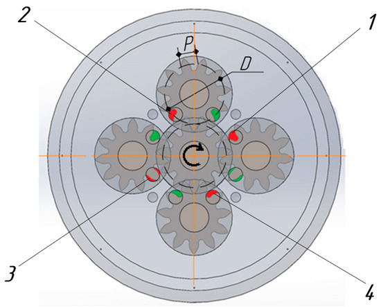
Figure 3.
Degree of opening of the suction and discharge ports in the pump housing: red color—discharge channels (1–4); green color—suction channels; D—pitch diameter; P—tooth pitch.
The different degrees of opening of the holes can also be confirmed by calculation [29]:
- -
- Pitch diameter of gears: d = m·z, where m is the tooth module, mm; z is the number of teeth;
- -
- Circumference length along the pitch diameter: L = π·d;
- -
- Gear pitch P = π·m, which corresponds to a gear rotation angle of (2·180o)/z.
Four driven gears are symmetrically arranged around the drive gear with a distance between the centers equal to 90° or L/4. Thus, the moments of gear engagement will be shifted in time by an angle of φ = (2·180°)/4·z = 180°/2·z.
The flowchart (Figure 4) clearly shows that using several driven gears around the drive gear can improve the smoothness and uniformity of the flow (Q). Curves 1–4 characterize the displacement of fluid from the pump working chambers with a time shift of φ = 180°/2·z.
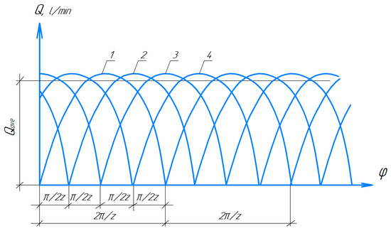
Figure 4.
Multi-gear pump flowchart. 1—curve characterizing the volume of fluid displaced through discharge channel 1; 2—curve characterizing the volume of fluid displaced through discharge channel 2; 3—curve characterizing the volume of fluid displaced through discharge channel 3; 4—curve characterizing the volume of fluid displaced through discharge channel 4.
In addition, all the fluid pumped from the working chambers flows into the manifold, where the displaced flows are combined into one.
2.3. Test Stand
To conduct tests and determine the output characteristics of a prototype multi-gear pump, KB “Hansa-Flex Hydraulik Almaty” LLP (Karaganda, Kazakhstan) developed a laboratory test bench for monitoring, adjusting, and regulating the hydraulic parameters of the fluid flow, as well as measuring them (Figure 5).
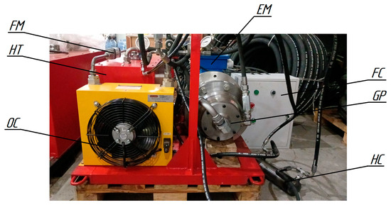
Figure 5.
Test stand. GP—prototype of a multi-gear pump; FC—frequency converter; EM—electric motor; FM—flow meter; HT—hydraulic tank; OC—oil cooler; HC—hydraulic cylinder.
The hydraulic scheme of the test stand is presented in Figure 6, and the list of hydraulic elements with the description of technical parameters is displayed in Table 1.
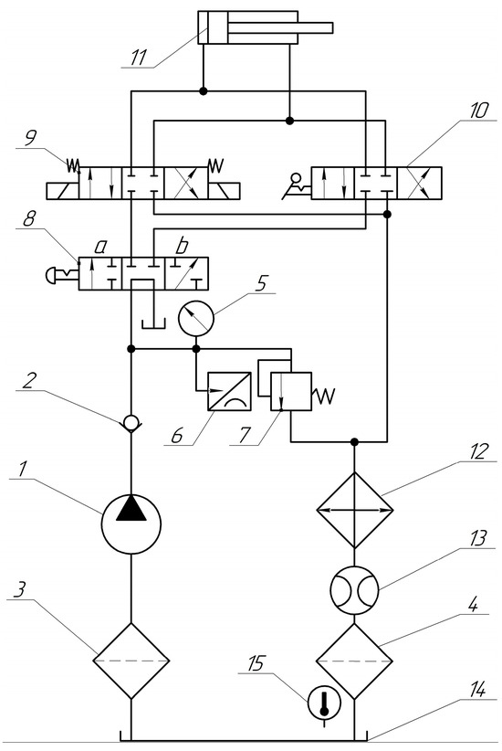
Figure 6.
Hydraulic diagram of the test stand: 1—prototype gear pump; 2—check valve; 3, 4—filters; 5—pressure gauge; 6—pressure sensor; 7—safety valve; 8—4/3-valve with manual control (crane); 9—4/3-valve with electromagnetic control; 10—4/3-valve with manual control; 11—hydraulic cylinder; 12—oil cooler; 13—flow meter; 14—hydraulic tank; 15—thermometer.

Table 1.
Components for the multi-gear pump test stand.
The prototype of multi-gear pump 1 injects fluid into the system, the pressure of which is determined by the setting of safety valve 7. Crane 8 is designed to unload the pump and supply fluid either to hydraulic valve 9, if provided for electric control, or to hydraulic valve 10 with manual control. Hydraulic cylinder 11 is needed to create load in the hydraulic system.
Pressure gauge 5 is designed to adjust and measure the pressure in the hydraulic system, as well as pressure sensor 6. Flow meter 13 installed in the drain line determines the flow rate of the fluid supplied by pump 1. Thermometer 15 is used to measure and control the temperature of the fluid. Filters 3 and 4 and oil cooler 12 are necessary to maintain the quality of the fluid.
2.4. Tested Characteristics and Test Procedure
The control and measuring equipment is designed for the characterization of the hydraulic parameters: pressure, pump delivery, and oil temperature. In addition, measurements of the noise level created by the pump were taken. As a working fluid, we used thickened all-season oil hydraulic VMGZ (GOST 17479.3).
The pump was tested in the following order:
- (1)
- Using the screw of safety valve 7 and pressure gauge 5, the pressure in the hydraulic system was adjusted to the values of 5; 10; 15; 20; and 26 MPa. When adjusting, hydraulic valve 8 must be switched to the working position (position a or b).
- (2)
- With the pressure set in the system during the tests, using the frequency converter, the rotation frequency of the drive shaft of the electric motor was regulated to the values of 1450; 1200; 900; 600; and 300 rpm.
- (3)
- Measurements of pump flow without load and with load were taken with the help of a flow meter.
- (4)
- Measurements of the pump noise level were taken with a noise meter.
- (5)
- The temperature of the working fluid was monitored with a thermometer.
3. Results and Discussion
3.1. Determining Speed at Kinematic Viscosity
In order to analyze the experimental data obtained, all the results are presented graphically.
Figure 7 shows the pump characteristics when varying the shaft speed from 300 to 1450 rpm at setting pressure Pcl = 26 MPa and kinematic viscosity coefficient 45 cSt. Analysis of the graphs shows that with an increase in speed, all the pump parameters increase linearly. The main interest is the volumetric efficiency, with the help of which the value of fluid leakage is estimated. In the speed range of 1000 ÷ 1450 rpm, the efficiency values are as high as 0.7–0.88. A reduction in shaft speed leads to an increase in leakage; the efficiency decreases to 0.3; and the pressure, pumped by the pump, falls to 9 MPa.
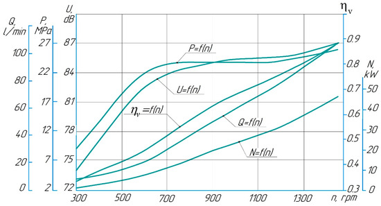
Figure 7.
Pump output characteristics as a function of rotational speed at kinematic viscosity coefficient ν = 45 cSt.
The pump’s capacity increases in direct proportion to the rotation speed from 6 to 105.3 L/min, as it is related to the product Q = q·n·ηv: q—the working volume of the pump, n—the rotational speed, and ηv—the volumetric efficiency [32]. In turn, this increase in performance and pressure leads to an increase in power consumption from 1.05 to 45.6 kW. The noise level also increases with intensity decreasing from 74 to 87 dB.
Thus, an increase in rotational speed from 300 to 1450 rpm leads to an increase in the flow rate from 1.75 to 89.5 L/min, the pressure in the system increases from 3.5 to 26 MPa, the power consumption increases from 0.1 to 38.8 kW, the volumetric efficiency increases from 0.1 to 0.75, and the noise level increases from 78.1 to 88 dB. It should be noted that in both cases, at kinematic viscosity coefficients of ν = 45 cSt and 15 cSt (Figure 7 and Figure 8), the pump operates more steadily and stably at speeds from 700 to 1450 rpm since in this range, the pump delivers a pressure close to the safety valve setting pressure of 24–26 MPa, and the noise level reaches values of 85–87 dB (Figure 7) and 88 dB (Figure 8).
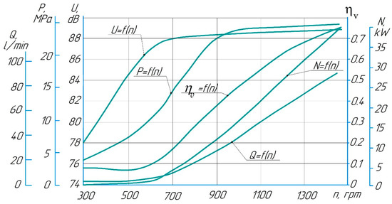
Figure 8.
Pump output characteristics as a function of rotational speed at kinematic viscosity coefficient ν = 15 cSt.
The output characteristics of the pump when the kinematic viscosity coefficient is reduced to 15 cSt due to heating the fluid to 40 °C are graphically presented in Figure 6.
A reduction in the kinematic viscosity coefficient leads to a general reduction in all characteristics by about 15–20%, except for the noise level, of which the value increased by 2 dB compared to the first experience.
3.2. Determination of Working Fluid Pressure at Rotational Speed
Figure 9a,b show the output characteristics of the pump as a function of pressure in the range from 5 to 26 MPa at constant speed (n = 900 rpm and n = 1200 rpm). As can be seen from the graphs, the nature of the behavior of the curves is identical. Thus, an increase in speed leads to a linear increase in useful power from 2.06 to 19.5 kW at n = 900 rpm and from 5.86 to 31.15 kW at n = 1200 rpm.
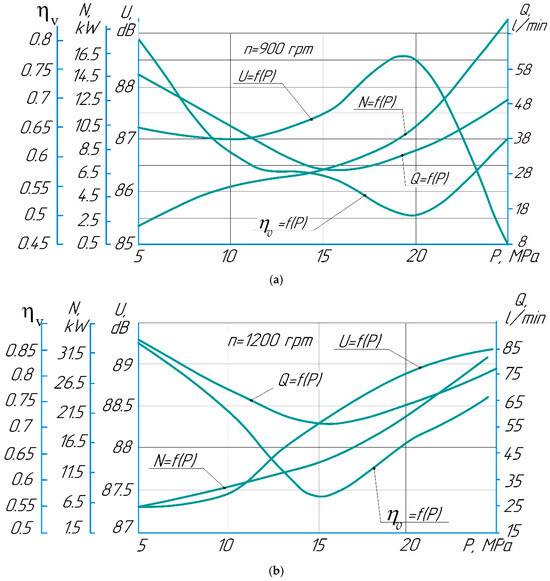
Figure 9.
Pump output characteristics as a function of working fluid pressure at rotational speed n = const and fluid kinematic viscosity coefficient ν = 45 cSt.
When the safety valve is set to 15 MPa in both cases, the pump provides a minimum flow rate (curves Q = f(P)) equal to 29.8 and 56.16 L/min, respectively. At n = 1200 rpm, the curve ηv = f(P) has a minimum at the point with coordinates P = 15 MPa and ηv = 0.571, and at n = 900 rpm at the point with coordinates P = 20 MPa and ηv = 0.51. High values of volumetric efficiency are found in the pressure range from 5 to 10 MPa. The noise level reaches maximum values of 88.5–88.9 dB in the pressure range of 15–20 MPa.
Dependences P = f(Q) of the positive displacement pump at n = 300 ÷ 1450 rpm, the pressure of the safety valve setting 26 MPa, and the coefficient of kinematic viscosity of fluid ν = 45 cSt are shown in Figure 10. Here, it is noted that with the increase in the pump pressure, the leakage of the working fluid ΔQ increases. For example, at speed n = 1450 rpm (curve V), the leakage in the pump ΔQ amounted to 4 L/min.
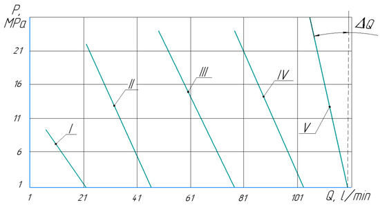
Figure 10.
Pump characteristic P = f(Q) at different values of shaft rotational speed: curve I—for n = 300 rpm; curve II—for n = 600 rpm; curve III—for n = 900 rpm; curve IV—for n = 1200 rpm; curve V—for n = 1450 rpm.
The experiment shows that the amount of internal leakage in the pump also depends on the shaft speed. For example, at a supply pressure in the system of 22 to 25 MPa and a rotational speed of n = 1450 rpm (curve V), the leakage in the pump ΔQ is 4 L/min; at a rotational speed of n = 600 rpm (curve II), the leakage in the pump ΔQ = 24.6 L/min; and at a rotational speed of n = 900 rpm (curve III), the leakage in the pump ΔQ = 28 L/min.
A comparative analysis of the pump characteristics with a change in the kinematic viscosity coefficient for a rotation speed of n = 900 rpm is shown in Figure 11.
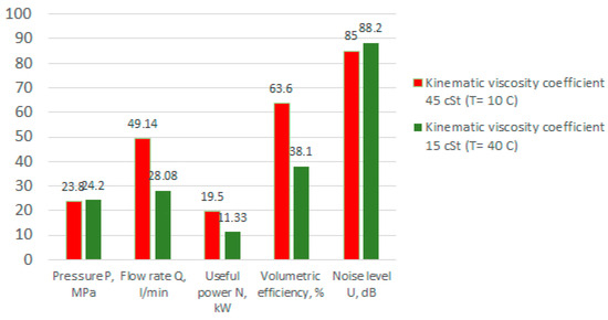
Figure 11.
Comparative analysis of the characteristics of a pump with a working fluid at different values of the kinematic viscosity coefficient.
In general, the analysis of the obtained experimental data allows us to note that the proposed design of the multi-gear pump is efficient. The best performance can be achieved at a rotation speed of n = 900–1450 rpm, since with a decrease in frequency, the pump performance decreases, and the fluid leaks increase. The operating pressure reaches 25 MPa.
It is worth noting that when the pump operates on a more viscous fluid, the volumetric efficiency is 25% higher, which causes higher values of feed and hydraulic power. The pressure in both cases is almost the same; the difference in values can be caused by inaccurate safety valve adjustment. The noise level of the operating pump is higher when it operates with a less viscous fluid.
To minimize and account for potential sources of error, the main sources of error in the measuring equipment were assessed:
- -
- Flow meter—2%;
- -
- Manometer—1.5%;
- -
- Noise meter—2%.
The systematic measurement error was as follows: for measurements of rotational speed—2.5%; for pressure measurements—2%; and for noise measurements—2%.
The measurement results can be trusted because, in order to obtain stable readings, measurements were taken only after the pump and system had reached a steady state of operation, excluding the influence of transient processes. The data were processed in the NetCracker 4.1 system [33].
Regarding recommendations on the possibility of further using and adjusting the design of the prototype multi-gear pump, the following can be noted:
- -
- Use the prototype for further studies of dynamic and energy characteristics;
- -
- Adjust the design documentation based on the test results;
- -
- Use the prototype pump and test results to improve the design;
- -
- Carry out work to improve the technological effectiveness of the pump’s structural elements, and improve the pump’s sealing system;
- -
- Improve the design of the multi-gear pump housing and its gears in order to minimize clearances through manufacturing technology.
The following results were obtained over the course of this study:
- (1)
- It was found that the most efficient operation of the pump is achieved in the range of drive shaft speeds from 900 to 1450 rpm. In this range, the volumetric efficiency demonstrates rather high values varying from 0.7 to 0.88 when working with VMGZ hydraulic oil with a kinematic viscosity of 45 cSt.
- (2)
- Reducing the speed below 900 rpm leads to a significant increase in internal leakage and a drop in volumetric efficiency to 0.3 at 300 rpm, as well as a decrease in the developing pressure to 9 MPa at a valve setting pressure of 26 MPa.
- (3)
- When the kinematic viscosity decreases from 45 cSt to 15 cSt (due to heating up to 40 °C), there is an overall reduction in capacity and power of about 15–20%, while the noise level increases slightly by 2 dB.
- (4)
- There is a linear dependence of the increase in useful power with increasing system pressure, reaching 19.5 kW at 900 rpm and 31.15 kW at 1200 rpm at a maximum pressure of 26 MPa.
- (5)
- Maximum noise levels recorded in the range of 88.5–88.9 dB at pressures of 15–20 MPa at 900 and 1200 rpm.
- (6)
- The expected increase in operating fluid leakage with increasing pressure was also observed, amounting to 4 L/min at 1450 rpm and 26 MPa pressure.
- (7)
- The optimal characteristics for this multi-gear pump design are operating pressure—5–25 MPa; rotation speed—900–1450 rpm.
4. Conclusions
The developed prototype addresses common gear pump drawbacks like unbalanced radial forces and uneven fluid delivery. The findings indicate optimal operation at drive shaft speeds of 900 to 1450 rpm, yielding volumetric efficiencies from 70% to 88% with VMGZ hydraulic oil. Lower speeds, such as 300 rpm, significantly increase internal leakage and decrease the volumetric efficiency to 30%. Reduced kinematic viscosity (from 45 cSt to 15 cSt) generally lowers the capacity and power by 15–20% but slightly increases the noise. The pump exhibits a linear increase in useful power with system pressure, reaching up to 31.15 kW. Optimal operating conditions are identified as 5–25 MPa pressure and 900–1450 rpm rotation speed.
The next research stages are as follows:
- -
- Adjusting the design documentation based on the test results;
- -
- Improving the manufacturability of pump components and the pump sealing system;
- -
- Optimizing the design of the housing and bottom cover of the multi-gear pump;
- -
- Lightening the design of the multi-stage pump;
- -
- Determining the most effective application of the pump in technological machines and equipment, taking into account factors such as power, expected operating and maintenance conditions, performance level, etc.
Author Contributions
Conceptualization, O.Z. and O.S.; methodology, O.R. and A.B. (Alexandra Berg); formal analysis, A.A., A.B. (Andrey Berg) and O.Z.; investigation, O.R. and D.Z.; resources, D.Z.; writing—original draft preparation, O.N., O.Z. and A.B. (Alexandra Berg); writing—review and editing, O.S. and O.N.; visualization, A.A. and A.B. (Andrey Berg), supervision, O.Z.; funding acquisition, O.Z. All authors have read and agreed to the published version of the manuscript.
Funding
This research is funded by the Science Committee of the Ministry of Science and Higher Education of the Republic of Kazakhstan (Grant of Young Scientists IRN No. AP19579208 “Creation of a universal prototype of a gear pump for hydraulic systems capable of pumping viscous fluids of various nature”).
Institutional Review Board Statement
Not applicable.
Informed Consent Statement
Not applicable.
Data Availability Statement
Data are contained within the article.
Conflicts of Interest
The authors declare no conflicts of interest.
References
- Zeleny, Z.; Vodicka, V.; Novotny, V.; Mascuch, J. Gear pump for low power output ORC—an efficiency analysis. Energy Procedia 2017, 129, 1002–1009. [Google Scholar] [CrossRef]
- Kravchenko, I.N.; Velichko, S.A.; Martynov, A.V.; Barmina, O.V.; Apatenko, A.S.; Sevryugina, N.S. Evaluation of the Operational Reliability of Gear Hydraulic Pumps Repaired Using the Electric Spark Processing Method. J. Mach. Manuf. Reliab. 2023, 52, 220–226. [Google Scholar] [CrossRef]
- Lakshmanana, K.; Tessicini, F.; Gil, A.J.; Auricchio, F. A fault prognosis strategy for an external gear pump using Machine Learning algorithms and synthetic data generation methods. Appl. Math. Model. 2023, 123, 348–372. [Google Scholar] [CrossRef]
- Rituraj, R.; Vacca, A. Investigation of flow through curved constrictions for leakage flow modeling in hydraulic gear pumps. Mech. Syst. Signal Process. 2021, 153, 107503. [Google Scholar] [CrossRef]
- Choudhuri, K.; Biswas, N.; Mandal, S.K.; Mitra, C.; Biswas, S. A numerical study of an external gear pump operating under different conditions. Mater. Today Proc. 2022; in press. [Google Scholar] [CrossRef]
- Frosina, E.; Senatore, A.; Rigosi, M. Study of a High-Pressure External Gear Pump with a Computational Fluid Dynamic Modeling Approach. Energies 2017, 10, 1113. [Google Scholar] [CrossRef]
- Ghionea, I.G.; Ghionea, A.L.; Ćuković, S.; Pleşa, M.I. Analysis on the measurement results of the precision grades and their influence on the performance of the hydraulic pumps with spur gears. In IOP Conference Series: Materials Science and Engineering; IOP Publishing: Bristol, UK, 2019; Volume 682, p. 012005. [Google Scholar] [CrossRef]
- Zhao, X.; Vacca, A. Theoretical Investigation into the Ripple Source of External Gear Pumps. Energies 2019, 12, 535. [Google Scholar] [CrossRef]
- Li, G.; Zhang, L.; Han, W. Profile design and displacement analysis of the low pulsating gear pump. Adv. Mech. Eng. 2018, 10, 168781401876700. [Google Scholar] [CrossRef]
- Fiebig, W. Influence of the Inter Teeth s on the Noise Generation in External Gear Pumps. Arch. Acoust. 2015, 39, 261–266. [Google Scholar] [CrossRef]
- Bakman, I.; Gevorkov, L.; Vodovozov, V. Optimization of method of adjustment of productivity of multi-pump system containing directly connected motors. In Proceedings of the Engineering Electric Power Quality and Supply Reliability Conference (PQ), Rakvere, Estonia, 11–13 June 2014. [Google Scholar] [CrossRef]
- Schänzle, C.; Störmer, N.; Pelz, P.F. Modeling the efficiency of external gear pumps based on similarity considerations. In Proceedings of the 2018 Bath/ASME Symposium on Fluid Power and Motion Control FPMC, Bath, UK, 12–14 September 2018. [Google Scholar] [CrossRef]
- Zhao, X.; Vacca, A. Formulation and optimization of involute spur gear in external gear pump. Mech. Mach. Theory 2017, 117, 114–132. [Google Scholar] [CrossRef]
- Opperwall, T.; Vacca, A. Combined FEM/BEM model and experimental investigation into the effects of fluid-borne noise sources on the air-borne noise generated by hydraulic pumps and motors. Proc. Inst. Mech. Eng. Part C 2014, 228, 457–471. [Google Scholar] [CrossRef]
- Xu, B.; Liu, Q.; Zhu, Z.; Gao, Y.; Li, C.; Zhang, Y. Influence of the Rotation Speed on the Internal Flow Characteristics of an Aircraft Fuel Gear Pump. Processes 2024, 12, 576. [Google Scholar] [CrossRef]
- Antoniak, P.; Stryczek, J. Visualization study of the flow processes and phenomena in the external gear pump. Arch. Civ. Mech. Eng. 2018, 18, 1103–1115. [Google Scholar] [CrossRef]
- Corvaglia, A.; Rundo, M.; Bonati, S.; Rigosi, M. Simulation and Experimental Activity for the Evaluation of the Filling Capability in External Gear Pumps. Fluids 2023, 8, 251. [Google Scholar] [CrossRef]
- Ferrari, C.; Morselli, S.; Miccoli, G.; Hamiche, K. Integrated CFD-FEM approach for external gear pump vibroacoustic field. Front. Mech. Eng. 2024, 10, 1298260. [Google Scholar] [CrossRef]
- Egbe, E.A.P. Design Analysis and Testing of a Gear Pump. Res. Inventy. Int. J. Eng. Sci. 2013, 3, 1–7. [Google Scholar]
- Yanikoren, M. Experimental investigation of the performance and energy consumption efficiency of elliptical gear hydraulic pump and evaluation by Taguchi method. Eng. Sci. Technol. Int. J. 2025, 62, 101941. [Google Scholar] [CrossRef]
- Dalmis, S.; Eruslu, O.; Bahtiyar, M. Experimental Test of Hydraulic External Gear Pumps. In Proceedings of the International Scientific Conference, Gabrovo, Bulgaria, 17–18 November 2017; pp. 422–427. [Google Scholar]
- Zhan, P.; Yan, Q.; Jiang, Z.; Yang, R.; Wei, L. Study on Mechanism and Suppression Method of Flow-Induced Noise in High-Speed Gear Pump. Arch. Acoust. 2024, 49, 49–60. [Google Scholar] [CrossRef]
- Metalsi, T.F.; Bourdim, A. Study of feasibility of plastic gear to reduce noise in a gear pump. Adv. Prod. Eng. Manag. 2012, 7, 143–149. [Google Scholar] [CrossRef]
- Kaczmarczyk, T.Z. Experimental research of a pumping engine in a micro-ORC system with a lowboiling medium. Arch. Thermodyn. 2024, 45, 125–140. [Google Scholar] [CrossRef]
- Kaczmarczyk, T.; Ihnatowicz, E.; Żywica, G.; Kaniecki, M. Experimental study of the prototype of a Roto-Jetpump for the domestic ORC power plant. Arch. Thermodyn. 2019, 40, 83–108. [Google Scholar] [CrossRef]
- Awais, M.; Ashraf, M.; Zaidi, Z. Investigating the Characteristics of a Gear Pump. Int. J. Med. Res. Health Sci. 2025, 14, 1–8. [Google Scholar]
- Zhang, X.H.; Liu, P.Y.; Wei, W.J.; Li, H.T.; Tian, G.P. Chapter: Design and simulation analysis of a new type of multi-gear pump. In Civil, Architecture and Environmental Engineering; CRC Press: London, UK, 2017. [Google Scholar] [CrossRef]
- Guerra, D.; Polastri, M.; Battarra, M.; Suman, A.; Mucchi, E.; Pinelli, M. Design Multistage External Gear Pumps for Dry Sump Systems: Methodology and Application. Math. Probl. Eng. 2021, 2021, 1–11. [Google Scholar] [CrossRef]
- Zharkevich, O.; Nikonova, T.; Gierz, Ł.; Reshetnikova, O.; Berg, A.; Warguła, Ł.; Berg, A.; Wieczorek, B.; Łykowski, W.; Nurzhanova, O. Improving the Design of a Multi-Gear Pump Switchgear Using CFD Analysis. Appl. Sci. 2024, 14, 5394. [Google Scholar] [CrossRef]
- Zharkevich, O.; Reshetnikova, O.; Nikonova, T.; Berg, A.; Berg, A.; Zhunuspekov, D.; Nurzhanova, O. CFD-FEM Analysis for Functionality Prediction of Multi-Gear Pumps. Designs 2024, 8, 115. [Google Scholar] [CrossRef]
- Zharkevich, O.; Nikonova, T.; Gierz, Ł.; Berg, A.; Berg, A.; Zhunuspekov, D.; Warguła, Ł.; Łykowski, W.; Fryczyński, K. Parametric Optimization of a New Gear Pump Casing Based on Weight Using a Finite Element Method. Appl. Sci. 2023, 13, 12154. [Google Scholar] [CrossRef]
- Radzevich, S. Dudley’s Handbook of Practical Gear Design and Manufacture; CRC Press: Boca Raton, FL, USA; Taylor & Francis Group: Oxfordshire, UK, 2016. [Google Scholar]
- Yakubova, M.Z.; Serikov, T.G.; Mekhtiev, A.D.; Yurchenko, A.; Alkina, A.D.; Neshina, Y.G. Development and imitating modeling in the developed network consisting of several knots removed among themselves on NetCracker 4.1. In Proceedings of the 2016 Dynamics of Systems, Mechanisms and Machines (Dynamics), Omsk, Russia, 15–17 November 2016; p. 7819108. [Google Scholar] [CrossRef]
Disclaimer/Publisher’s Note: The statements, opinions and data contained in all publications are solely those of the individual author(s) and contributor(s) and not of MDPI and/or the editor(s). MDPI and/or the editor(s) disclaim responsibility for any injury to people or property resulting from any ideas, methods, instructions or products referred to in the content. |
© 2025 by the authors. Licensee MDPI, Basel, Switzerland. This article is an open access article distributed under the terms and conditions of the Creative Commons Attribution (CC BY) license (https://creativecommons.org/licenses/by/4.0/).
