1. Introduction
The chemical industry is confronted with various challenges such as an uncertain supply of raw materials, globalization of markets and volatile energy markets. Solutions for these challenges are currently investigated in many areas of chemical engineering. This includes, e.g., new developments in process systems engineering [
1] and process synthesis [
2], but also in approaches such as process intensification [
3,
4] and demand-side-management [
5]. In most of these areas, improving the flexibility of chemical systems is seen as a key element to deal with the increasing uncertainties.
There has been significant research on how to quantify and enhance flexibility for chemical systems based on the work of Grossmann and his coworkers for steady-state operation [
6,
7], which was also extended for dynamic operation [
8]. The developed mathematical methods are powerful tools to adapt and retrofit chemical processes in terms of their flexibility [
9]. These methods can be employed to optimize process parameters in order to increase flexibility. Besides these methods, new technical approaches are being developed to allow for a more flexible operation of process systems. The solutions encompass approaches for scheduling and control, and the advancement of existing unit operations. Research for scheduling and control is widely available [
10,
11,
12,
13,
14,
15], whereas advancements in unit operations are scarce. Some examples can be found in reaction engineering [
16,
17]. This is also particularly applicable for separation technologies such as distillation columns.
The flexibility of a distillation column in terms of its feed mass flow largely depends on the type of internals. If the feed capacity of the column changes considerably, different hydrodynamic phenomena occur that limit the feasible region of the column. When perturbation of these limits appear, products might become off-spec or the operation fails completely. Flexible operation, therefore, requires a column design that can operate over a wide range of operating points while maintaining safe operation and satisfying product specifications.
Such a column design was introduced by Riese and Grünewald [
18] for a tray distillation column. The proposed design separates a distillation column into radial segments. Each segment can be operated independently, and additional segments can be activated or deactivated to provide capacity flexibility. Capacity flexibility describes the ability of the column to operate feasibly during significant and intended feed fluctuations [
19]. Riese and Grünewald [
18] showed, by steady-state simulations, that the segmented column provides significant improvements in terms of flexible operation compared to a standard column design. The segmented column features the flexibility of single standard columns in an integrated fashion. A more detailed technical description and first results on the practicality of the segmented distillation column can be found in [
20].
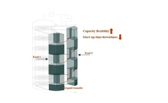
The activation of adjacent segments in the segmented column is enabled by connecting the downcomer on each tray (see
Figure 1). Controlled rods that create openings between the downcomer allow the exchange of liquid. When the liquid flow reaches an inactive segment, the start-up of that segment begins. This is where another crucial aspect of flexible operation becomes relevant, which is fast transient behavior and the minimization of downtime during operation. The aim of the connection between the segments is also to reduce the start-up time of inactive segments by transferring steady-state temperature and concentration profiles from the already active segments. The start-up behavior of such an inactive segment despite the different geometry resembles the start-up of a conventional distillation column.
In the literature, several works exist that deal with the start-up of distillation columns experimentally or theoretically. There are studies on a variety of different applications such as batch distillation [
21], continuously operated distillation [
22], heat integrated distillation [
23] or reactive distillation [
24]. Niggemann et al. [
25] give a further overview of work aimed specifically at optimizing the start-up procedure of distillation columns to minimize the start-up time.
Modeling and simulation are commonly used to determine switching points of variables during start-up or to compare start-up strategies. Various studies confirm that simulation models are able to successfully represent hydrodynamic and thermodynamic phenomena during the start-up of distillation columns of different types [
26,
27,
28]. One of the first computational works to describe the start-up of a distillation column was proposed by Ruiz et al. [
29]. Accordingly, the start-up process can be separated into the following three phases: a discontinuous phase, in which hydraulic variables undergo large changes in a discontinuous manner; a semi-continuous phase, in which the thermodynamic variables behave strongly non-linearly; and a continuous phase, in which the concentrations in the column slowly reach a steady state.
The possibilities available to optimize the start-up strongly depend on the specific application. For standard columns, strategies such as total distillate removal [
30], the manipulation of variables such as reflux rate and heat duty [
31] or applying control techniques [
32] turned out to be beneficial. The characteristic MX-function introduced by Yasuoka [
33] is often applied to determine switching points in start-up strategies [
30], or as a measure for reaching a steady-state [
24]. Depending on the strategy during start-up, the semi-continuous and especially the continuous phase take up a large part of the time needed for start-up [
25,
34]. Therefore, shortening the time required for these phases means decreasing the overall start-up time.
Considering the literature, it becomes apparent that utilizing the liquid from an active segment in the segmented column should result in a significant decrease in the start-up time of inactive segments. This is because the liquid provided by the active segment is already at a steady state, thereby reducing the time the column remains in the semi-continuous and continuous phases during start-up.
Motivated by the above, in this paper, we analyze the start-up behavior of inactive segments within the segmented column by means of dynamic simulation. In case of significant feed fluctuation, minimizing the start-up time of inactive segments means minimizing downtime during operation. We develop a detailed dynamic column model and perform simulation studies of the segmented distillation column and compare those to columns with standard geometry. We assess a scenario in which the feed capacity increases significantly so that the operation of distillation columns in parallel or the segmented distillation column is required for the production to remain feasible. For this scenario, we chose a methanol and water mixture as a representative separation task, as it is among the recommended test mixture for distillation columns [
35], has already been used in other start-up studies [
26,
32] and is well known. In light of this work, we address the following questions:
Which new degrees of freedom for start-up strategies result from the segmented column design?
What influence do these degrees of freedom have on the start-up time of inactive segments?
What advantages does the integrated column design provide compared to separately operated columns?
2. Dynamic Column Model
The start-up of a distillation column is a highly complex task. During the start-up, hydraulic and thermodynamic variables undergo significant changes. The developed model has to account for the individual changes in these variables. A typical equilibrium stage model requires modifications, as it is not able to describe the transition from a dry and cold state to operating conditions. In the literature, a frequently used approach is to implement mathematical switches in the model structure to change between the different thermodynamic and hydrodynamic states [
23,
24,
26,
36].
To cover the complete range of states that occur during start-up, we include equations for non-equilibrium behavior, equilibrium behavior and the different hydrodynamic phenomena in the developed model. These equations are switched by if–else conditions. Equations that are switched include, e.g., a dummy equation that sets the liquid flow to the next stage to zero and the Francis Weir equation. Further explanation of the switching conditions can be found in [
26,
36]. Furthermore, the model consists of algebraic equations for the equilibrium condition, the physical properties and the tray hydraulics. The variables and equations for this model and the different states that switch are listed in
Appendix A in
Table A1.
Since we want to simulate the start-up not only of a single segment or a standard column, but also of additional segments that are connected via the downcomer, the developed dynamic column model also needs to consider downcomer dynamics in order to correctly predict downcomer backup during start-up. This connection between each downcomer on each tray, which is accounted for in the model, is a major difference from standard column models. Due to the fact that liquid is supposed to flow from one downcomer to the adjacent one, flow equations have to be developed that predict the correct behavior of the liquid in the downcomer, but also on each connected tray. Additionally, the heat balance must be considered for each downcomer, since the effects of heating the adjacent segment by the side stream must be accounted for.
The model was implemented in Aspen Custom Modeler
® and the properties for the components were retrieved from an Aspen Properties
® subroutine. For a better understanding, a tray in the segmented distillation column is depicted in
Figure 2. The tray is divided into separate control volumes for the equilibrium stage and the downcomer.
In the following, the equations for the equilibrium stage and the downcomer of each stage are described. Then, the approach for connecting the downcomer to the equilibrium stage and the segment of the column is presented.
2.1. Equilibrium Stage
The MESH equations for the equilibrium stage are presented below. Index
i indicates the components and index
j indicates the theoretical stage.
where
is the liquid or vapor molar hold-up,
is the temperature and
is the mass of each stage.
,
and
indicate feed, vapor and liquid molar flows, entering and leaving the stage. In the energy balance (Equation (2)), the heat capacity of the liquid, the vapor and the column wall and internals are considered. The thermodynamic properties of the methanol and water mixture are affected by the non-linear behavior in the liquid phase. Therefore, we chose the NRTL property package with an ideal vapor assumption to calculate the thermodynamic properties. At the beginning of the start-up process, the column is far from the equilibrium state. The equations for the non-equilibrium state describe liquid and heat accumulation. The equilibrium conditions are only valid at bubble-point temperature. Once the bubble-point temperature is reached, the equations are switched to the equilibrium state. We assumed that all the vapor entering the stage is condensed until the temperature on each stage reaches the equilibrium state. The weeping of liquid must be accounted for, as we employ sieve trays at each stage. In this case, we apply a correlation presented by Staak et al. [
37]. The correlation considers a parameter
that indicates the appearance of weeping.
accounts for the F-factor in the holes of the tray, while
is the clear liquid height and
the area of holes on the tray. The parameters for the weeping correlation
can be found in [
37]. During the start-up simulation of additional segments, trays might run dry if the liquid backup is not sufficient. This can lead to significant numerical instabilities due to the mathematical formulation of the Torricelli equation. To avoid numerical singularities, the following stabilization equation proposed by Wunderlich [
38] is applied, as an approximation of the Torricelli equation:
where
and
.
indicates the velocity of the liquid leaving the tray by weeping. The pressure on each stage is calculated by the following equation:
The pressure drop
considers dry and liquid pressure drop for sieve trays. Correlations are taken from Zuiderweg [
39].
The Francis Weir equation [
40] is applied to calculate the flow of liquid over the weir into the downcomer as soon as the liquid height has reached the weir height. Both the liquid and vapor phases are considered in the holdup calculations. The liquid holdup is dependent on the tray geometry, the tray hydraulics and the physical properties as follows:
The gas hold-up is obtained from the stage volume and the liquid hold-up as follows:
2.2. Downcomer
To determine the dynamic behavior of the liquid flow through the downcomer and to the next segment, the downcomer backup needs to be predicted. Therefore, the downcomer is modelled separately. The following equations represent the composition and energy balances as well as the molar fraction summation within the downcomer:
The vapor volumes of the tray and downcomer are combined and thus, vapor hold-up in the downcomer is neglected. The liquid hold-up is calculated as a function of the downcomer geometry and the incoming and outgoing flows. In the equations of the downcomer, the molar side streams to and from the adjacent segment are considered.
2.3. Connection between Downcomer and Stage
To account for downcomer dynamics, the model needs to include equations to connect the equilibrium stage and the downcomer. Typically, the liquid backup in the downcomer is calculated directly from a steady-state momentum balance Equation (16) [
40].
where
,
,
,
and
are the steady-state clear liquid height, the total pressure drop, the weir height, the height of crest over weir and the head loss due to liquid flow under the downcomer apron. Nevertheless, this approach is not always correct during start-up. As gas flows through the holes of the trays, the solution of the equation predicts a rise in the backup of the downcomer. However, the liquid does not rise in the downcomer when there is a pressure drop on the stage. Instead, it rises as soon as there is a significant backflow, and the downcomer apron is sealed.
We assume a flow from and to the downcomer that is based on Torricelli’s law and the derived discharge equation of a submerged rectangular orifice. The approach considers the discharge of liquid from the downcomer to the stage, as well as the resistance against the discharge induced by the two-phase flow on the stage as follows:
where
and
are the actual clear liquid heights in the downcomer and on the stage. The flow from the stage to the downcomer is calculated similarly as follows:
where
describes the area under the downcomer apron. The resistance coefficient for the flow towards the downcomer
only accounts for the friction under the apron and is, therefore, set to 0.6. The resistance coefficient for the flow to the stage
is calculated considering the steady-state momentum balance. By rearranging Equation (17) and using the stationary values from Equation (16), the resistance coefficient
is obtained as follows:
It is assumed that the liquid height on the stage and in the downcomer is nearly equal until the liquid reaches the height of the weir and a significant backflow occurs from the stage above to the downcomer. This is implemented in the model by an additional mathematical switch.
2.4. Connection between Segments
The side stream from the downcomer of an active segment to the adjacent segment is included in the material and energy balance (see
Figure 2). The flow from and to adjacent segments is assumed, similar to the approach from the previous section, on the basis of Torricelli’s law, thereby, considering the height of the liquid in the individual downcomer. The incorporation of equations for the incoming and outgoing heat and mass flows between the segments during start-up is unique compared to state of the art models.
Figure 3 shows the overall structure of the model.
As can be seen, the model has an analogous layout for each segment. Each segment consists of an individual condenser, trays with radial flow, a reflux drum and a reboiler, and is controlled by a PI controller in a standard LV-configuration [
41]. The adjacent segments are interconnected across all stages, except for the first stage. It is assumed that the first stage has no downcomer.
At this point, we consider no heat transfer between the segments and the overall column is adiabatic. We assume that both the segments and the outer layer of the column are well isolated. The distillate and bottom products are merged at the top and bottom of the column. Therefore, the product specification is dependent on the performance of all the segments.
3. Case Study
The segmented column design is best suited for scenarios with a strongly fluctuating feed capacity. Therefore, the aim of this case study is to investigate the advantages of the segmented design for such a scenario. We assume that due to external effects, flexible operation of the distillation column is required. This can be caused, e.g., by the results of the scheduling of an upstream process for demand-side management. In this scenario, it is not possible to operate a single distillation column, as this would result in a violation of the hydrodynamic boundaries. Instead, either two distillation columns with standard geometry in parallel or the segmented distillation column with two segments are applied. We assume that either one standard column or one segment of the segmented column is active and at a steady state. Now the feed increases significantly (
to
) so that either an additional standard column or a segment has to be activated. In both cases, the distillate product is the indicator for the column to reach a steady state at which production can be resumed. The assumptions for the case study are visualized in
Figure 4 to provide a better understanding. The standard distillation column is designed in Aspen Plus
® v10 under the paradigm that the active area is equal to the active area of a single segment of the segmented column. The hydrodynamic boundaries that prevent the operation of one distillation column in the scenario such as weeping, jet flood and minimum and maximum weir load are calculated with an Aspen Plus subroutine. The design specifications for the columns are given in
Table 1.
A conventional start-up procedure for tray columns is applied to the case study, which is commonly used in the literature [
42,
43,
44]: heat is supplied into the reboiler as soon as the liquid level in the column sump reaches the set point, which is, in this case, a 0.5-m liquid height; the reboiler duty is increased step-wise and then set to the steady-state value; the reflux ratio remains constant during start-up. The liquid level controller in the sump and reflux drum, and the pressure controller at the condenser are active during start-up. The temperature controller is set to active as soon as a steady state is reached to prevent large temperature gradients.
The design of the segmented column provides new degrees of freedom to optimize the activation, i.e., start-up process of segments: first, liquid can be transferred to adjacent segments through the downcomer; second, the timing at which feed is introduced to single segments can be varied; third, the additional flow from adjacent segments is expected to allow liquid to reach the sump earlier, which enables the timing of the heat supply to the reboiler of each segment to change. By combining these new degrees of freedom, five different cases are analyzed in this simulation study.
The base case is the start-up of an inactive segment of the segmented column (BCsegmented) or a standard column (BCstandard) solely with the feed according to the described conventional start-up strategy. The base case serves as a reference case for all further cases.
All other cases refer exclusively to the segmented column design. In the first case (C1), liquid is flowing from the active segment to the adjacent, inactive segment. The feed is introduced into the inactive segment as soon as the connection between the segments is enabled on each tray. In the second case (C2), the feed to the inactive segment is introduced later once a fluid profile in the segment is formed. Until this point in time is reached, the additional feed for the inactive segment is fed to the active segment. In the third case (C3), the time, when feed is introduced is similar to case C2. Additionally, the heat supply to the sump of the segment is started earlier, when the set-point reaches half of its value. In the fourth case (C4), heat duty is supplied even earlier to the sump of the column than in case C3. Since there is no experience with the start-up of this type of column, the time at which heat duty is supplied is chosen according to the start-up experience of the conventional distillation columns [
29]. In case C4, the time until heat is supplied is shortened to such an extent that the liquid accumulation in the sump during the start-up process is just sufficient to prevent damage to the column equipment. The different assumptions for the cases are summarized in
Figure 5.
The steady-state conditions for each of the investigated cases are determined using the following MX-function defined by Yasuoka [
33]:
where
is the actual liquid mole fraction of component
on stage
and
is the liquid mole fraction at steady-state conditions. If the MX-function permanently falls under a value of 0.01, the system is assumed to be at a steady state. The MX-function is calculated for the distillate MX
distillate, the bottom product MX
bottom and the overall column or segment MX
overall.
4. Simulation Results
The simulation results for all the cases are listed in
Table 2. For the base case of the segmented column, a steady state is reached after 3.99 h at the top of the column and 7.61 h for the overall column. In comparison, the time required until a steady state is achieved for the base case of the column with standard geometry is 4.26 h at the top and 7.25 h for the entire column. It is noticeable that the calculated start-up time for the bottom product is comparatively short for both column designs (0.37 h vs. 0.34 h). This is because the high volatility of methanol causes it to dissolve quickly from the water and, consequently, the purity of the bottom product quickly reaches a steady state. In general, since the start-up times for the base case differ only slightly, it is evident that a single segment behaves analogously to a column with standard geometry. It should be noted that the chosen start-up strategy influences the time to reach a steady state for all the scenarios. The stepwise increase in the heat supply is a rather conservative strategy that can be further improved by an appropriate optimization of the control actions. However, this strategy is, indeed, very reliable in avoiding steep temperature gradients in the column reboiler.
In case C1, liquid from the active segment is introduced to the inactive segment through the downcomer. The liquid has the temperature and concentration profiles from the active, stationary segment. As can be seen by comparing case C1 to the base case in
Figure 6, the hot side streams enter the inactive segment and directly heat-up the stages. In addition, the combined liquid flows from the feed and the active segments increase liquid accumulation in the sump, reducing the time until the set-point is reached. Thus, the heat supply to the reboiler of the segment begins earlier. The time, until a steady state at the top of the segmented column is reached, is reduced by 28.74%. The overall time is reduced by 16.25%. As expected, these results show that the liquid transfer between the segments, i.e., the use of stationary profiles for the start-up of the inactive segment, has an impact on the start-up time. However, the effect appears to be rather small when comparing the start-up time of case C1 to the base case.
Figure 7 shows that mixing the side streams and the fresh feed has a strong influence on the temperature and concentration profiles. At the beginning of the start-up in case C1, the MX-function has a steep gradient. The concentrations in the second segment approach a steady state quickly. Then, gas rises in the column and as the liquid accumulates on the stages, mixing with fresh feed slows the approach to a steady state. The general trend of the MX functions of case C1 and the base case can be considered similar. From these results, it can be deduced that one aim of improving the start-up procedure is to reduce the effects of mixing since the steady-state concentration and temperature profiles of the active segment are easily disturbed.
The transfer of liquid to the inactive segment also influences the concentrations in the active segment. This can be noticed by considering
Figure 8. During the activation of the adjacent segment, the concentrations in the active segment significantly diverge from the steady state. The hydraulic and thermodynamic variables such as liquid holdup and temperatures on each tray undergo considerable changes while liquid leaves the active segment. However, as can be seen, the disturbances in the active segment can be compensated faster than the inactive segment requires to be activated. This conclusion has also been found for all the subsequent cases.
In case C2, the point at which the feed is introduced into the second segment is further delayed. In this way, an additional reduction in the start-up time is obtained. In comparison to the base case, the time until the distillate reaches a steady state is reduced by 57.67%. The overall time until a steady state is reached is reduced by 31.42%. As can be seen in
Figure 7, the system is able to better compensate for the disturbances caused by the feed. While the gradient at the beginning is lower than in case C1 due to the reduced liquid intake to fill the column, the system is only disturbed by the later increase in the heat duty to the reboiler (cf.
Figure 7 at 0.1 h). These observations coincide with the findings of Ruiz et al. [
29] that, during the semi-continuous phase, compositions tend to get disturbed relatively easily by changes in other variables. The curve of the MX-function for case C2 is less affected by the effects of mixing with the feed and, thus, approaches a steady state faster.
During the start-up of distillation columns, it is necessary to fill the sump of the column with liquid to a certain extent before heat is supplied to prevent the reboiler from running dry. This is particularly important when sieve trays are used. While the vapor rises within the column and seals the holes in the trays, the liquid is prevented from reaching the stage below as long as the liquid height on the stage has not yet reached the weir height. Thus, if the liquid backup in the sump is not sufficient and the backflow of the liquid is not reaching the sump fast enough, the start-up of the column might fail. However, the literature indicates that a reduction in the liquid level in the reboiler might improve the start-up duration [
23,
25]. In the case of the segmented distillation column, the side stream flow allows liquid to reach the sump of the column earlier. This permits a column start-up with less liquid backup in the sump.
On this basis, the results for case C3 are obtained. In case C3, the time until the top of the column reaches a steady state is reduced by 77.12% and the time required for the overall column is reduced by 41.57% in comparison to the base case.
Figure 7 illustrates these results and shows that the earlier heat supply leads to a reduction in the inertia of the system. The inertia of the system during start-up is characterized by the ability of the concentrations to recover from external disturbances. Comparing the MX-functions at the top of the column for cases C2 and C3 in
Figure 9 emphasizes this conclusion. The peak of the curve at around 0.1 h is caused by the change in the heat supply. This peak is lower for case C3, indicating that the system is able to better compensate for this disturbance.
By assessing the liquid backup in the sump of the segment during start-up in case C3, it is apparent that the backup is sufficient for the entire start-up process. It is, therefore, possible to supply the reboiler with heat even earlier during start-up, which further reduces the available liquid backup. This is investigated in case C4.
Figure 7 shows that an even earlier heat supply during start-up leads to further amplification of the effects observed in case C3. The concentrations for case C4 quickly approach the steady-state values. The start-up time is reduced by 95.92% at the top of the segmented column and by 60.12% for the overall column compared to the base case. In general, it becomes apparent from cases C3 and C4 that a lower total mass of the components within the column during start-up results in a reduction in the start-up time.
Figure 10 shows a comparison of the results for the segmented distillation column and the distillation columns with standard geometry. It is evident that the segmented distillation column offers significant advantages in terms of flexible operation compared to standard distillation columns operated in parallel. While the start-up of the first segment takes about the same time as the distillation column with standard geometry (3.99 h vs. 4.25 h), the start-up time of an additional segment in the segmented column can be greatly reduced (0.16 h vs. 4.25 h). In addition, for a segmented column with more than two segments, it takes only 0.16 h for another segment to be activated. The time advantage, therefore, increases with the number of segments operated in one column shell.
It should be noted that the segmented column is highly specialized for specific tasks. If flexible operation is a crucial aspect for the separation task under consideration, the segmented design with the connection of the downcomer not only offers to significantly reduce downtime, but also the storage capacities. If continuous operation is required for the considered scenario, both the standard columns operated in parallel and the segmented column would require a buffer storage to bridge downtime. This is the case since during the capacity increase, both the first column and the first segment would reach their hydrodynamic boundaries and production would not be feasible. The buffer storage has to be sufficiently large so that the liquid backup can bridge the time until an additional column or segment is activated. Furthermore, the results of this case study indicate that the start-up of tray distillation columns independent of their geometry benefits from preloading the trays with already stationary liquid.
5. Conclusions and Outlook
In this work, we examined a segmented distillation column design by dynamic simulation. The segmented column design enables capacity flexible operation by allowing the segments to be operated separately. Each segment within the column is connected via an opening mechanism through the downcomer. The transfer of liquid between the adjacent segments aims to reduce the time required to activate additional segments.
We developed a dynamic pressure-driven model that includes downcomer dynamics and accounts for the connection between the segments. In a case study on the separation of methanol and water, we analyzed the new degrees of freedom to intervene during a start-up associated with the segmented distillation column design and compare the segmented column to standard tray columns. The results show that using the liquid at a steady state from an active segment (C1) improves the start-up time of the inactive segments. However, the feed of the inactive segment disturbs the already stationary concentration profiles and thus, has a negative effect on the improvement. By delaying the feed introduction (C2), the disturbances caused are significantly reduced. In addition, earlier heat-supply to the reboiler (C3) becomes possible. Due to the coupling of the segments, the liquid reaches the sump more quickly, thus avoiding damage to the equipment that might occur during start-up. By combining these aspects, the start-up time is reduced by up to 95.92% for the distillate and 60.12% for the overall column (C4). These results confirm the advantages of the proposed distillation column design over standard tray distillation columns in situations where production capacities change frequently. The segmented distillation column offers an extended operating window, while enabling the feed flow to shift quickly between significant changes, and due to that, minimizing downtime and the storage capacities.
The results of the case study are solely theoretical. Therefore, experimental studies should be carried out to validate the results and further define the actual technical implementation of the segmented column. Furthermore, the cases in this study are derived from the literature. The actual timing at which control actions are executed during start-up, e.g., when a segment reaches the boundaries of its operating window during operation and an additional segment requires to be activated, needs to be investigated further. Mathematical optimization of the timing can help to improve the performance of the segmented column during flexible operation. Additionally, flexible operation of the segmented column should be investigated for plant-wide approaches in order to identify limitations and challenges that might occur due to control loop interactions with other unit operations.


