Article

Development of Heavy Metal-Free Photocatalytic RhB Decomposition System Using a Biodegradable Plastic Substrate

1
Global Environment Center for Education & Research, Mie University, Mie 514-8507, Japan
2
Department of Chemistry for Materials, Graduate School of Engineering, Mie University, Mie 514-8507, Japan
*
Author to whom correspondence should be addressed.
ChemEngineering 2021, 5(1), 11; https://doi.org/10.3390/chemengineering5010011
Submission received: 31 December 2020 / Revised: 29 January 2021 / Accepted: 22 February 2021 / Published: 3 March 2021
(This article belongs to the Special Issue Concentrated Solar Energy for Materials)

Abstract

:
The heavy-metal-free photocatalytic system, in which carbon nitride is coated on polylactic acid (PLA) as biodegradable plastic through a simple dip coating method, was used for dye decomposition under visible light irradiation. Solvent selection, solvent concentration, and the number of coatings for dip coating were investigated to optimize the conditions for loading carbon nitride on PLA. Carbon nitride cannot be coated on PLA in water, but it can be strongly coated by decomposing the surface of PLA with ethanol or chlorobenzene to promote physical adsorption and activate surface. The number of dip coatings also affected the photocatalytic decomposition ability. The photocatalytic system was able to decompose the dye continuously in the flow method, and dye (rhodamine B) was decomposed by about 50% at a residence time of 12 min (flow rate 0.350 mL/min) for 30 h.

1. Introduction

Sunlight is semi-permanent and clean energy, so it has been studied in fields such as power generation [1], interfacial evaporation [2], and photocatalysis [3]. Since the hydrogen production activity of TiO2 by the photocatalytic effect was confirmed by Fujishima and Honda in 1972, new photocatalysts such as ZnO, SiC, and CdS have been discovered [3,4]. It has been reported that the photocatalyst consumes only light as driving energy to generate hydrogen, fix CO2, and decompose organic substances. Therefore, it is expected as a clean method for decomposing toxic organic waste [5,6,7]. Rhodamine B (RhB) is a highly water-soluble, reddish-purple, basic red dye used primarily as a colorant in the textile and food industries. However, it has been shown to be toxic to the skin, eyes, respiratory tract, and digestive organs of humans and animals, and the carcinogenic and neurotoxic symptoms of rhodamine B have been experimentally demonstrated [8,9,10]. Most the synthesized photocatalysts are powders, and they are industrially disadvantageous because they are difficult to recover after performing the photocatalytic activity in water. To solve this problem, methods of photocatalytic coating on various substrates were investigated [11,12]. Loading of typical photocatalyst TiO2 on ceramic glass, fiber glass, sand, stainless steel, pebbles, plastic, and activated carbon has been reported [13,14,15,16,17,18]. Among these, plastic is advantageous as a metal-free substrate for a photocatalyst because it does not contain harmful metals, has excellent flexibility, and can be easily manipulated in shape. Oh et al. report the direct deposition of silver on PET film. They succeeded in producing a uniformly deposited thin silver layer by repeatedly depositing silver layers on PET by plasma reduction reaction [19]. However, ordinary plastics are precursors to microplastics and pollute the aquatic environment [20,21,22]. Biodegradable plastic is a desirable material to solve this problem. Biodegradable plastics are decomposed by microorganisms and by little residual remains such as microplastics [23]. Furthermore, since biodegradable plastics are made from plants such as sugar cane, their carbon neutrality suppresses an increase in CO2, which is advantageous for reducing the environmental pollution. Polylactic acid (PLA) has environmentally friendly properties such as being made from renewable agricultural resources such as sugar cane and biodegradable in soil and water [24,25,26]. In addition, PLA’s excellent thermal stability and mechanical properties allow it to be easily processed on standard plastic molding equipment to yield molded parts, films, or fibers. Therefore, it is used as a green chemical plastic to replace conventional petrochemical-based polymers for industrial applications. It has been confirmed that lactic acid is dissolved in organic solvents such as ethanol, butanol, isopropanol, chlorobenzene, and bromethane [27,28,29,30,31,32]. It may be possible to directly coat powdered photocatalysts with these organic solvents by dissolving the surface of the PLA and promoting physical adsorption. Photocatalysts using heavy metals have a high performance of photocatalytic activity due to their high conductivity and appropriate position of band structure [33,34,35]. However, most heavy metals have some harmful effects on the human body, so exposure to the environment is not recommended. C3N4, as a metal-free photocatalyst, has been attracting much research interest due to its precursors, which are inexpensive and have chemical and thermal stability and a narrow band structure suitable for visible light response [36,37,38]. Decomposition of various dyes by the photocatalytic system using C3N4 has been reported (rhodamine b [39], methyl orange [40], malachite green [41], crystal violet [42], and methylene blue [43]). However, the photocatalytic activity of g-C3N4 is limited by its low specific surface area and fast photogenic electron–hole pair recombination. To eliminate these problems, Liang et al. developed nanotube C3N4 using the molten salt method [44,45]. This study provides a photocatalytic flow system for decomposing organic materials that do not use heavy metals for both PLA as a substrate and nanotube C3N4 as a photocatalyst to emphasize environmental friendliness (Supplementary Table S1).

2. Materials

Preparation and Characterization of Photocatalysts

All reagents (analytical reagent grade) were used as received in this research. Melamine (Kanto Chemical Co., Inc., Tokyo, Japan), lithium chloride (Wako Pure Chemical Industries, Ltd., Osaka, Japan), sodium chloride (Wako Pure Chemical Industries, Ltd., Japan), potassium chloride (Wako Pure Chemical Industries, Ltd., Japan), ethanol (Kanto Chemical Co., Inc.), chlorobenzene (Nacalai Tesque, Inc., Kyoto, Japan), Rhodamine B (Kanto Chemical Co., Inc.), and distilled water were used in this work.
Nanotube C3N4 photocatalysts were prepared by one step molten salt synthesis reported by Liang et al. [44,45]. Melamine 1g, LiCl 5 g, KCl 5 g, and NaCl 5 g were mixed in an agate bowl. The mixture was melted and calcined for 2 h, put in an alumina crucible with cover at a heating rate of 10 °C/min in a muffle furnace at 500 °C, and naturally cooled to room temperature in the furnace and denoted as NT-500. For comparison, pure C3N4 was prepared in the same way, except that no metal salts were added and denoted as M-500.

3. Methods

3.1. Characterization of Photocatalysts

In order to estimate the crystal structure of the prepared photocatalyst, the X-ray powder diffraction (XRD) pattern of the photocatalyst was measured with a Rigaku RINT Ultima-IV diffractometer using Cu radiation in a scan range of 0–80° (scan speed: 0.04°/s). A scanning electron microscope (SEM) equipped with Hitachi S-4000 was used to observe the morphology of each photocatalyst prepared. The photoluminescence (PL) spectrum of each photocatalyst was detected using a Shimadzu RF-5300PC at an excitation wavelength of 350 nm.
An uncoated PLA ring (diameter = 1 cm, length = 1 cm) made from Japanese companies 3 g washed with distilled water was immersed in a 0.5 w/v% NT-500 suspension 40 mL in ultrasound for 5 min and vacuum dried at 60 °C. Then, distilled water was added, and the mixture was vigorously shaken and vacuum dried several times to remove excess photocatalyst. In order to investigate the solvent of the suspension, a mixed solution of water, ethanol (EtOH), and ethanol–chlorobenzene (EtOH–C6H5Cl) mixture (volume ratio of 9:1) was used as the solvent. A PLA ring immersed in a mixed solution of ethanol and chlorobenzene without photocatalyst was prepared as a reference substance. To investigate the relationship between the number of dip coatings and the photocatalytic activity, PLA rings dip-coated with NT-500 once, three times, and five times were prepared. The prepared NT-500 coated PLA ring was labeled as “used solvent (number of dip coatings)”.

3.2. Set up Photocatalytic RhB Degradation by Flow System and Batch System

Photocatalytic RhB degradation studies by flow system were carried out in the following condition. C3N4-coated PLA ring 3 g and RhB solution (5 ppm) 42 mL were put into 50 mL pyrex glass reactor. A xenon lamp (intensity 6000–7000 µW/cm2) equipped with a cut-off filter (λ > 420 nm) was used as the visible light source. The photocatalytic degradation system was kept in the dark for 30 min to establish the adsorption-desorption equilibrium between photocatalyst and RhB. After that, while irradiating with light for 6 h, samples were taken out from the reactor periodically. In order to investigate the catalyst load of the photocatalytic system, RhB was decomposed under two conditions of the flow rate of 0.700 mL/min (residence time of 6 min). The concentration of RhB was measured at the 554 nm absorbance using a spectrophotometer (Shimadzu UV- 3600 plus) equipped with an integral sphere assembly (Table 1). For comparison, powdered C3N4 was used to degrade RhB for 1 h under similar conditions (Supplementary Table S2).

4. Results and Discussion

4.1. Photocatalytic Characterization

The results of the photoluminescence (PL) spectrum are shown in Figure S1. The PL spectrum can effectively characterize charge carrier transfer and separation. From Supplementary Figure S1, a dramatic decrease in the peak intensity of C3N4 was observed by using a molten salt for preparation. This may be due to the fact that the formation of the porous structure promoted the separation of photogenerated electron-hole pairs, and the increase in charge carrier transfer rate suppressed the recombination of electron-hole pairs. From the SEM image of Supplementary Figure S2, M-500 was bulky, and many nanotube morphologies were seen in NT-500. The specific surface area of the sample was measured by the Brunauer–Emmett–Teller method (BET method). Supplementary Table S3 shows the specific surface area, average pore diameter, and total pore volume. The surface area was increased from 14.1 cm2/g to 52.4 cm2/g by using the molten salt method, due to the difference in shape between the bulk M-500 and the NT-500 having a nanotube morphology. The XRD pattern of the prepared C3N4 photocatalyst is shown in Figure 1a. In C3N4, two strong peaks of 27.5° and a weak peak of 13.1° found in a typical heptadine-based C3N4 phase were detected. These are indexed as (0 0 2) face-to-face heptazine inter-stacking and (1 0 0) face-in-plane structural motif diffraction planes, respectively [36,37]. From the prepared UV-vis diffuse reflectance spectrum (DRS) of C3N4 (Figure 1b), the absorption edge was determined to be 460 nm, suggesting light absorption under visible light (λ > 420 nm). These results were consistent with reported results, indicating that C3N4 was prepared [37,44].

4.2. Photocatalytic Activity

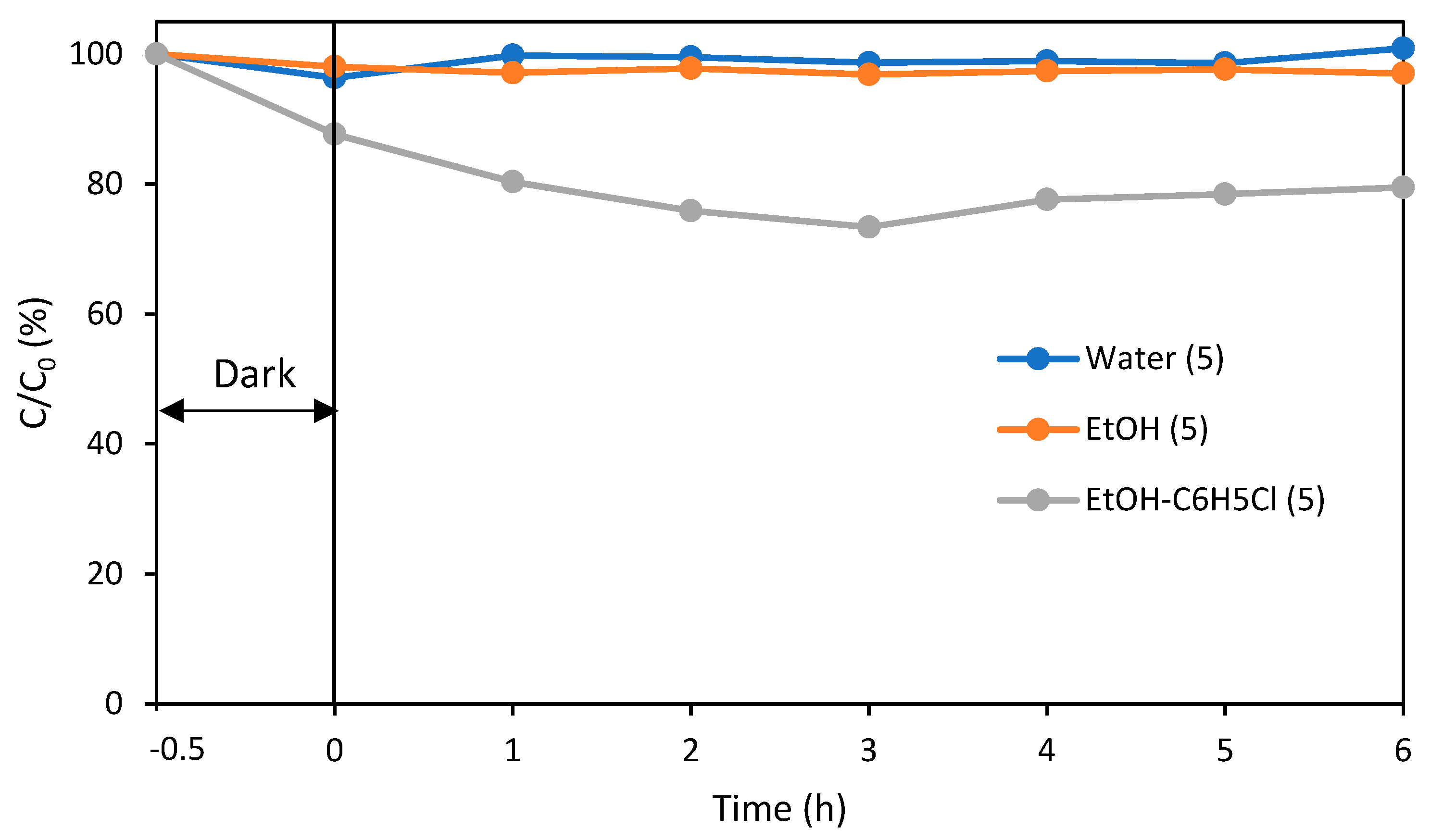
The results of photocatalytic RhB degradation under the flow method conditions (flow rate 0.700 mL/min) using a PLA ring dip-coated with NT-500 five times using a 5 w/v% NT-500 suspension solution with water, ethanol, or an ethanol–chlorobenzene mixed solution as the solvent are shown in the Figure 2. Upon irradiation with visible light for 6 h, the NT-500-coated PLA ring with water as the solvent did not decolorize RhB, and the one with EtOH decolorized slightly. When EtOH–C6H5Cl was used as a solvent, it was decolorized by about 20% (Figure 2). In comparison, Supplementary Figure S3 shows the results of evaluating the photocatalytic activity of the RhB degradation experiment in a batch system. Prior to irradiation, the RhB solution containing the photocatalyst was stirred in the dark for 30 min until absorption/desorption equilibrium was reached. M-500 and NT-500 degraded RhB by about 10% and 55% in 1 h, respectively. The improvement in photocatalytic activity of NT-500 is due to the decrease in electron-hole pair recombination rate and the increase in specific surface area.
In order to compare the differences between the prepared photocatalytic systems, we changed the experimental conditions to Table 2 and conducted RhB degradation experiments. Figure 3 shows the number of dip coatings of a photocatalyst system using ethanol and a mixed solution of ethanol–chlorobenzene as a solvent for dip coating, and the decomposition efficiency of RhB during the flow method (flow rate 0.350 mL/min). When ethanol and chlorobenzene–ethanol mixed solution were used as the dip coating solution, the dip coating number of three times showed higher RhB decolorization rate than one time, but it was almost the same between three times and five times. Under similar conditions, no degradation was observed in the photocatalytic RhB degradation experiment using a PLA ring without NT-500.
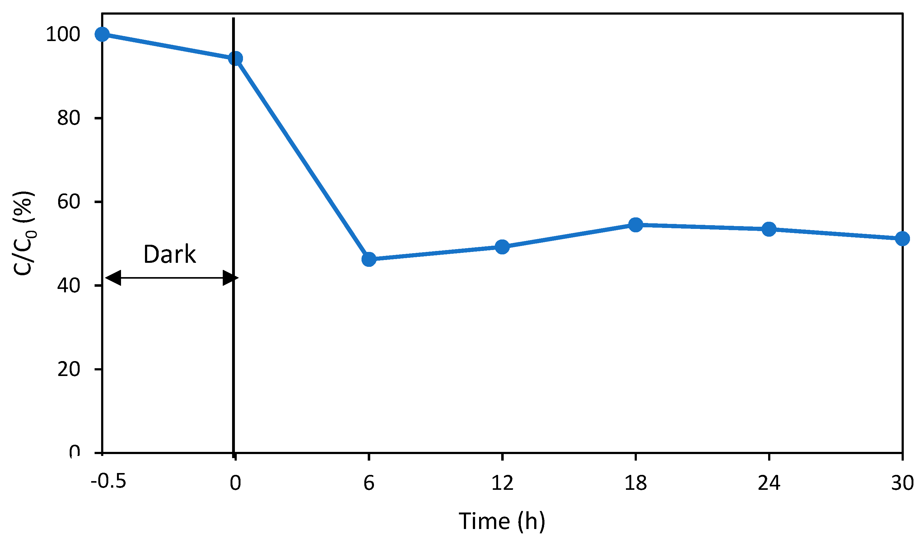
To investigate the stability of the photocatalytic system, the results of a 30-h continuous RhB degradation experiment under visible light in a flow method (flow rate 0.350 mL/min) using a carbon nitride coated PLA ring with EtOH–C6H5Cl as the solvent and five dip coating times are shown in Figure 4. From the result of RhB continuous decomposition experiment for 30 h, about 50% decomposition was shown in 6 h, and about 50% decomposition efficiency was continuously maintained from 6 h to 30 h. Supplementary Table S4 shows the comparison of the performance between other photocatalytic dye degradation systems with the one in this study [46,47,48,49].
The degradation results of RhB by the batch method and the flow method show that the prepared C3N4 is a visible light-responsive photocatalyst, that RhB is not removed only by PLA ring, and that C3N4 dip-coated on biodegradable plastic maintains photocatalytic activity. The effect of the number of dip coatings on the degradation efficiency of RhB showed that it increased the amount of C3N4 loaded on PLA and the degradation efficiency of RhB depended on the deposition amount of C3N4. Then, it was suggested that the number of coatings was limited. Additionally, the solvent for coating was not only ethanol; ethanol and a small amount of chlorobenzene improved the degradation efficiency of RhB. This phenomenon was due to the fact that more powdered C3N4 was loaded on the PLA ring because chlorobenzene had a higher ability to dissolve the PLA surface than ethanol. The mechanism of RhB degradation with C3N4 under visible light has been reported in several studies [39,50]. C3N4 is excited by visible light to photo-generate electrons and holes, which reduce oxygen to O2−. O2− and holes decompose RhB into CO2, H2O, and some intermediates. In this study, C3N4 deposited on plastics showed the above decomposition ability.

5. Conclusions

Biodegradable plastics and a C3N4 composite noble metal-free photocatalyst system were used via the dip coating method using chlorobenzene and ethanol as a solvent for degrading RhB. When loading C3N4 onto PLA, the best RhB decomposition efficiency was obtained under the condition that 0.5 w/v% NT-500 suspension solution with ethanol–chlorobenzene mixed solution was dip-coated three times or more. When the photocatalytic activity was evaluated by the flow method, it was confirmed that 20% and 50% of 10 ppm RhB were degraded at flow rates of 0.700 mL/min and 0.350 mL/min, respectively. The stability of the photocatalytic activity of the photocatalytic system was suggested by the continuous decomposition experiment of RhB by the flow method for 30 h.

Supplementary Materials

The following are available online at https://www.mdpi.com/2305-7084/5/1/11/s1. Table S1: Comparison of photocatalyst and substrate environmental friendliness, Table S2: Experimental conditions for degradation RhB by batch method under visible light irradiation, Table S3: BET areas, total pore volume, and average pore diameter of M-500 and NT-500, Figure S1: Photoluminescence spectra of M-500 and NT-500, Figure S2: SEM images of (a) M-500 and (b) NT-500, Figure S3: Photocatalytic RhB degradation of the C3N4 (M-500 and NT-500).

Author Contributions

I.T. and H.K. conceived and designed the experiments. I.T. performed the experiments and wrote the paper. I.T., M.F., S.K., and H.K. analyzed the results and advised the project. All authors have read and agreed to the published version of the manuscript. Note: All experiments were conducted at Mie University. Any opinions, findings, conclusions, or recommendations expressed in this paper are those of the authors and do not necessarily reflect the view of the supporting organizations.

Funding

This research received no external funding.

Conflicts of Interest

The authors declare no conflict of interest.

References

  1. Singh, G.K. Solar power generation by pv (photovoltaic) technology: A review. Energy 2013, 53, 1–13. [Google Scholar] [CrossRef]
  2. Dao, V.D.; Vu, N.H.; Yun, S. Recent advances and challenges for solar-driven water evaporation system toward applications. Nano Energy 2020, 68, 104324. [Google Scholar] [CrossRef]
  3. Kudo, A. Development of photocatalyst materials for water splitting. Int. J. Hydrog. Energy 2006, 31, 197–202. [Google Scholar] [CrossRef]
  4. Kato, H.; Kudo, A. Photocatalytic water splitting into H2 and O2 over various tantalate photocatalysts. Catal. Today 2003, 78, 561–569. [Google Scholar] [CrossRef]
  5. McCullagh, C.; Robertson, J.M.C.; Bahnemann, D.W.; Robertson, P.K.J. The application of TiO2 photocatalysis for disinfection of water contaminated with pathogenic micro-organisms: A review. Res. Chem. Intermed. 2007, 33, 359–375. [Google Scholar] [CrossRef]
  6. Zou, W.; Gao, B.; Ok, Y.S.; Dong, L. Integrated adsorption and photocatalytic degradation of volatile organic compounds (VOCs) using carbon-based nanocomposites: A critical review. Chemosphere 2019, 218, 845–859. [Google Scholar] [CrossRef]
  7. Kahng, S.; Yoo, H.; Kim, J.H. Recent advances in earth-abundant photocatalyst materials for solar H2 production. Adv. Powder Technol. 2020, 31, 11–28. [Google Scholar] [CrossRef]
  8. Jain, R.; Mathur, M.; Sikarwar, S.A. Mittal Removal of the hazardous dye rhodamine B through photocatalytic and adsorption treatments. J. Environ. Manag. 2007, 85, 956–964. [Google Scholar] [CrossRef] [PubMed]
  9. Rochat, J.; Demenge, P.; Rerat, J.C. Toxicologic study of a fluorescent tracer: Rhodamine b Toxicol. Eur. Res. 1978, 1, 23–26. [Google Scholar]
  10. Merouani, S.; Hamdaoui, Q.; Saoudi, F. Sonochemical degradation of Rhodamine B in aqueous phase: Effects of additives. Chem. Eng. J. 2010, 158, 550–557. [Google Scholar] [CrossRef]
  11. Byrne, J.A.; Eggins, B.R.; Brown, N.M.D.; Mckinney, B.; Rouse, M. Immobilisation of TiO2 Powder for the Treatment of Polluted Water. Appl. Catal. B Environ. 1998, 17, 25–36. [Google Scholar] [CrossRef]
  12. Pozzo, R.L.; Baltanas, M.A.; Cassano, A.E. Supported Titanium Dioxide as Photocatalyst in Water Decontamination: State-of-Art. Catal. Today 1997, 39, 219–231. [Google Scholar] [CrossRef]
  13. Bideau, M.; Claudel, B.; Dubien, C.; Faure, L.; Kazouan, H. On the immobilization of titanium dioxide in the photocatalytic oxidation of spent waters. J. Photochem. Photobiol. A 1995, 91, 137–144. [Google Scholar] [CrossRef]
  14. Zhang, Y.; Crittenden, J.C.; Hand, D.W.; Parram, D.L. Fixed-bed photocatalysts for solar decontamination of water Environ. Sci. Technol. 1994, 28, 435–442. [Google Scholar] [CrossRef]
  15. Ao, C.H.; Lee, S.C.; Yu, J.C. Photocatalyst TiO2 Supported on Glass Fiber for Indoor Air Purification: Effect of NO on the Photodegradation of CO and NO2. J. Photochem. Photobiol. A 2003, 156, 171–177. [Google Scholar] [CrossRef]
  16. Rao, N.N.; Chaturvedi, V. Photoactivity of TiO2 Coated Pebbles. Ind. Eng. Chem. Res. 2007, 46, 4406–4414. [Google Scholar] [CrossRef]
  17. Gao, Y.; Liu, H.T. Preparation and Catalytic Property Study of a Heavy Kind of Suspended Photocatalyst of TiO2 activated Carbon Immobilized on Silicone Rubber Film. Mater. Chem. Phys. 2005, 92, 604–608. [Google Scholar] [CrossRef]
  18. Fernandez, A.; Lasaletta, G.; Jimenez, V.M.; Justo, A.; Gonzallez-Elipe, A.R.; Herrmann, J.M.; Tahiri, H.; Ait-Ichou, Y. Preparation and Characterization of TiO2 Photocatalysts Supported on Various Rigid Supports (Glass, Quartz and Stainless Steel). Comparative Studies of Photocatalytic Activity in Water Purification. Appl. Catal. B 1995, 7, 49–63. [Google Scholar] [CrossRef]
  19. Oh, H.J.; Dao, V.D.; Choi, H.S. Electromagnetic shielding effectiveness of a thin silver layer deposited onto PET film via atmospheric pressure plasma reduction. Appl. Surf. Sci. 2018, 435, 7–15. [Google Scholar] [CrossRef]
  20. Mani, T.; Primpke, S.; Lorenz, C.; Gerdts, G.; Burkhardt-Holm, P. Microplastic pollution in benthic mid-stream sediments of the Rhine River//Microplastic Pollution in Benthic Midstream Sediments of the Rhine River. Environ. Sci. Technol. 2019, 53, 6053–6062. [Google Scholar] [CrossRef]
  21. Zhang, K.; Sun, H. Adsorption of organic pollutants on (degradable) microplastics and the influences on their bioavailability. Environ. Chem. 2018, 37, 375–382. [Google Scholar]
  22. Isobe, A.; Iwasaki, S.; Uchida, K.; Tokai, T. Abundance of non-conservative microplastics in the upper ocean from 1957–2066. Nat. Commun. 2019, 10, 417. [Google Scholar] [CrossRef] [PubMed] [Green Version]
  23. Horton, A.A.; Jürgens, M.D.; Lahive, E.; Van Bodegom, P.M.; Vijver, M.G. The influence of exposure and physiology on microplastic ingestion by the freshwater fish Rutilus rutilus (roach) in the River Thames, UK. Environ. Pollut. 2018, 236, 188–194. [Google Scholar] [CrossRef]
  24. Eling, B.; Gogolewski, S.; Pennings, A.J. Biodegadable materials of poly (l-lactic acid). 1. Melt-spun and solution spun fibers. Polymer 1982, 23, 1587–1593. [Google Scholar] [CrossRef]
  25. Bordes, P.; Pollet, E.; Avérous, L. Nano-biocomposites: Biodegradable polyester/nanoclay systems. Prog. Polym. Sci. 2009, 34, 125–155. [Google Scholar] [CrossRef]
  26. Wu, Y.L.; Wang, H.; Qiu, Y.K.; Loh, X.J. PLA-based thermogel for the sustained delivery of chemotherapeutics in a mouse model of hepatocellular carcinoma. RSC Adv. 2016, 6, 44506–44513. [Google Scholar] [CrossRef]
  27. Savioli Lopes, M.; Jardini, A.L.; Maciel Filho, R. Poly (lactic acid) production for tissue engineering applications. Procedia Eng. 2012, 42, 1402–1413. [Google Scholar] [CrossRef] [Green Version]
  28. Farah, S.; Anderson, D.G.; Langer, R. Physical and mechanical properties of PLA, and their functions in widespread applications—A comprehensive review. Adv. Drug Deliv. Rev. 2016, 107, 367–392. [Google Scholar] [CrossRef] [PubMed] [Green Version]
  29. Anderson, K.S.; Schreck, K.M.; Hillmyer, M.A. Toughening polylactide. Polym. Rev. 2008, 48, 85–108. [Google Scholar] [CrossRef]
  30. Castro-Aguirre, E.; Iñiguez-Franco, F.; Samsudin, H.; Fang, X.; Auras, R. Poly (lactic acid)—Mass production, processing, industrial applications, and end of life. Adv. Drug Deliv. Rev. 2016, 107, 333–366. [Google Scholar] [CrossRef] [PubMed] [Green Version]
  31. Armentano, I.; Bitinis, N.; Fortunati, E.; Mattioli, S.; Rescignano, N.; Verdejo, R.; Lopez-Manchado, M.A.; Kenny, J.M. Multifunctional nanostructured PLA materials for packaging and tissue engineering. Prog. Polym. Sci. 2013, 38, 1720–1747. [Google Scholar] [CrossRef] [Green Version]
  32. Glotova, V.N.; Bikmullina, T.N.; Lukianov, A.E.; Novikov, V.T. Lactide and Lactic Acid Oligomer Solubility in Certain Solvents. Petrol. Coal 2016, 58, 585–589. [Google Scholar]
  33. Lee, G.-J.; Wu, J.J. Recent developments in ZnS photocatalysts from synthesis to photocatalytic applications—A review. Powder Technol. 2017, 318, 8–22. [Google Scholar] [CrossRef]
  34. Cheng, L.; Xiang, Q.; Liao, Y.; Zhang, H. CdS-Based photocatalysts. Energy Environ. Sci. 2018, 11, 1362–1391. [Google Scholar] [CrossRef]
  35. Gou, X.L.; Cheng, F.Y.; Shi, Y.H.; Zhang, L.; Peng, S.J.; Chen, J.; Shen, P.W. Shape-controlled synthesis of ternary chalcogenide ZnIn2S4 and CuIn(S,Se)2 nano-/microstructures via facile solution route. J. Am. Chem. Soc. 2006, 128, 7222–7229. [Google Scholar] [CrossRef] [PubMed]
  36. Samanta, S.; Martha, S.; Parida, K. Facile Synthesis of Au/g-C3N4 Nanocomposites: An Inorganic/Organic Hybrid Plasmonic Photocatalyst with Enhanced Hydrogen Gas Evolution Under Visible-Light Irradiation. ChemCatChem 2014, 6, 1453–1462. [Google Scholar]
  37. Zhang, R.; Li, P.; Wang, F.; Ye, L.; Gaur, A.; Huang, Z.; Zhao, Z.; Bai, Y.; Zhou, Y. Atomically dispersed Mo atoms on amorphous g-C3N4 promotes visible-light absorption and charge carriers transfer. Appl. Catal. B Environ. 2019, 250, 273–279. [Google Scholar] [CrossRef]
  38. Zhu, B.; Wageh, S.; Al-Ghamdi, A.; Yang, S.; Tian, Z.; Yu, J. Adsorption of CO2, O2, NO and CO on s-triazine-based g-C3N4 surface. Catal. Today 2019, 335, 117–127. [Google Scholar] [CrossRef]
  39. Yan, X.; Gao, Q.; Qin, J.; Hui, X.; Ye, Z.; Li, J.; Ma, Z. A facile method for fabricating TiO2/g-C3N4 hollow nanotube heterojunction and its visible light photocatalytic performance. Mater. Lett. 2018, 217, 1–4. [Google Scholar] [CrossRef]
  40. Tian, L.; Li, J.; Liang, F.; Wang, J.; Li, S.; Zhang, H. Molten salt synthesis of tetragonal carbon nitride hollow tubes and their application for removal of pollutants from wastewater. Appl. Catal. B Environ. 2018, 225, 307–313. [Google Scholar] [CrossRef]
  41. Huy, B.T.; Thao, C.T.B.; Dao, V.D.; Phuong, N.T.K.; Lee, Y.I. A mixed-metal oxide/graphitic carbon nitride: High visible light photocatalytic activity for efficient mineralization of Rhodamine B. Adv. Mater. Interfaces 2018, 4, 1700128. [Google Scholar] [CrossRef]
  42. Wang, S.M.; Li, D.L.; Sun, C.; Yang, S.G.; Guan, Y.; He, H. Synthesis and characterization of g-C3N4/Ag3VO4 composites with significantly enhanced visible-light photocatalytic activity for triphenyl methane dye degradation. Appl. Catal. B Environ. 2014, 144, 885–892. [Google Scholar] [CrossRef]
  43. Chang, F.; Xie, Y.; Li, C.; Chen, J.; Luo, J.; Hu, X.; Shen, J. A facile modification of g-C3N4 with enhanced photocatalytic activity for degradation of methylene blue. Appl. Surf. Sci. 2013, 280, 967–974. [Google Scholar] [CrossRef]
  44. Han, C.C.; Ge, L.; Chen, C.F.; Li, Y.J.; Xiao, X.L.; Zhang, Y.N.; Guo, L.L. Heavy visible light induced Co3O4-g-C3N4 heterojunction photocatalysts for efficient degradation of methyl orange. Appl. Catal. B Environ. 2014, 147, 546–553. [Google Scholar] [CrossRef]
  45. Hassani, A.; Eghbail, P.; Ekicibil, A.; Metin, Ö. Monodisperse cobalt ferrite nanoparticles assembled on mesoporousgraphitic carbon nitride (CoFe2O4/mpg-C3N4): A magnetically recoverable nanocomposite for the photocatalytic degradation of organic dyes. J. Magn. Magn. Mater. 2018, 456, 400–412. [Google Scholar] [CrossRef]
  46. Li, J.Y.; Yu, X.; Zhu, Y.; Fu, X.H.; Zhang, Y.M. 3D-2D-3D BiOI/porous g-C3N4/graphene hydrogel composite photocatalyst with synergy of adsorption-photocatalysis in static and flow systems. J. Alloy. Compd. 2021, 850, 156778. [Google Scholar] [CrossRef]
  47. Jain, P.; Kumar, A.; Verma, N.; Gupta, R.K. In-situ synthesis of TiO2 nanoparticles in ACF: Photocatalytic degradation under continuous flow. Sol. Energy 2019, 189, 35–44. [Google Scholar] [CrossRef]
  48. Wang, C.; Luo, S.; Liu, C.; Chen, C. WO3 quantum dots enhanced the photocatalytic performances of graphene oxide/TiO2 films under flowing dye solution. Inorg. Chem. Commun. 2020, 115, 107875. [Google Scholar] [CrossRef]
  49. Carbonaro, S.; Sugihara, M.N.; Strathmann, T.J. Continuous-flow photocatalytic treatment of pharmaceutical micropollutants: Activity, inhibition, and deactivation of TiO2 photocatalysts in wastewater effluent. Appl. Catal. B Environ. 2013, 129, 1–12. [Google Scholar] [CrossRef]
  50. Hao, R.; Wang, G.; Tang, H.; Sun, L.; Xu, C.; Han, D. Template-free preparation of macro/mesoporous g-C3N4/TiO2 heterojunction photocatalysts with enhanced visible light photocatalytic activity. Appl. Catal. B Environ. 2016, 187, 47–58. [Google Scholar] [CrossRef]
Figure 1. Characterization of powdered C3N4. (a) Pattern of XRD; (b) pattern of DRS (diffuse reflectance spectrum).
Chemengineering 05 00011 g001
Figure 2. Photocatalytic RhB degradation of the NT-500 coating polylactic acid (PLA) prepared in different solutions for coating under flow conditions (flow rate 0.700 mL/min).
Chemengineering 05 00011 g002
Figure 3. Photocatalytic RhB degradation of the NT-500 coating PLA prepared at different times of dip-coating (a) ethanol and (b) ethanol–chlorobenzene (flow rate 0.350 mL/min).
Chemengineering 05 00011 g003
Figure 4. Stability of photocatalytic system with EtOH–C6H5Cl as solvent for coating under flow method conditions (flow rate 0.350 mL/min).
Chemengineering 05 00011 g004
Table 1. Experimental conditions for degradation Rhodamine B (RhB) by flow method under visible light irradiation.
SampleRhodamine B (5 ppm, 42 mL)
TemperatureRoom temperature (25 °C)
PhotocatalystPLA rings/NT-500 (3 g)
Flow rate0.700 mL/min
Light sourceXenon lamp with cut filter
(6000–7000 μW/cm2, λ ≥ 420 nm)
Irradiation time0–6 h
AnalysisUV-visible spectrometer (554 nm)
Table 2. Experimental conditions for degradation RhB by flow method under UV-Vis light irradiation.
SampleRhodamine B (5 ppm, 42 mL)
TemperatureRoom temperature (25 °C)
PhotocatalystPolylactic acid rings/NT-500 (3 g)
Flow rate0.350 mL/min
Light sourceXenon lamp (15,000–16,000 μW/cm2)
Irradiation time0–6 h or 30 h
AnalysisUV-visible spectrometer (554 nm)
Publisher’s Note: MDPI stays neutral with regard to jurisdictional claims in published maps and institutional affiliations.