Abstract
Economically and ecologically, the thermal decomposition of methane is a promising process for large scale hydrogen production. In this experimental study, the non-catalytic decomposition of methane in the presence of small amounts of carbon dioxide was analyzed. At large scales, natural gas or biomethane are possible feedstocks for the thermal decomposition and can obtain up to carbon dioxide. Gas recycling can increase the amount of secondary components even further. Experiments were conducted in a packed flow reactor at temperatures from 1250 to 1350 . The residence time and the amounts of carbon dioxide and hydrogen in the feed were varied. A methane conversion of up to and a carbon dioxide conversion of up to were observed. At the hydrogen yield was for a feed of methane diluted in nitrogen. If carbon dioxide was added to the feed at up to a tenth with regard to the amount of supplied methane, the hydrogen yield was reduced to . Hydrogen in the feed decreases the reaction rate of the methane decomposition and increases the carbon dioxide conversion.
1. Introduction
Today, approximately of hydrogen is produced by methane steam reforming, oil/naphtha reforming and coal gasification [1]. All of these processes result in a significant amount of emission. Alternatively to the implementation of carbon capture and storage in the classical production processes [2], the emissions can be reduced by a change in the general production process [3]. Electrochemical water splitting (water electrolysis) in combination with renewably produced electricity is under consideration for hydrogen production [4]. The main challenges are the limited capacity, and high operational and investment costs [5]. From economic and ecological perspectives the thermal decomposition of methane (TDM) could be an interesting alternative for large-scale hydrogen production [6,7,8]. In an endothermic reaction, methane is dissociated to solid carbon and hydrogen:
Due to slow reaction kinetics and the strong C–H bond, a high temperature is crucial for reasonable methane conversions [9]. A catalyst allows a significant reduction of the reaction temperature. Typically, a metal or carbon catalyst is used [10].
Metal catalysts have the advantage of high initial catalytic activity, but due to carbon agglomeration in the active sites, the activity decreases rapidly. Mainly under consideration are Ni, Co and Fe-based catalysts. During methane decomposition over a metal catalyst, different nano-carbon types are formed that can improve the process’s economics as a valuable byproduct [11].
Carbon catalysts have the advantage of low costs and higher thermal stability [9]. Compared to metal catalysts, the activity is lower, but due to higher operation temperatures the hydrogen yield can be increased. In the literature, carbon black, activated carbon, graphite, nano-carbon types (SWCNT, MWCNT), glassy carbon, coal chars and coke have been evaluated as catalysts [12,13]. Due to carbon agglomeration in the micropores and mesopores of the catalyst, the number of active sites and the surface area decrease. Thus, the activity of the catalyst decreases as well [14]. The deposited carbon on carbon catalysts is disordered or turbostratic [15].
Non-catalyzed TDM needs to be operated at high temperatures to reach a high methane conversion. An advantage is the high purity of the produced carbon and there is no need to withdraw the deposited carbon from a catalyst. The reported deposited carbon types were carbon black [16,17] and graphite-like carbon [18]. The kinetics of the non-catalyzed TDM were extensively investigated in modeling and experimental studies [19,20,21,22,23,24]. Experiments are typically conducted while being dependent on the temperature and the residence time. However, only few studies are available where the feed gas mixture, except the type and amount of inert gas, was varied. In an early study of Kassel [19], it was found that a large hydrogen concentrations retard the reaction rate of the decomposition reaction. The experiments were conducted at a reaction temperature of . In contrast, Skinner et al. [20] observes in the temperature range of 1400–1800 no influence of the reaction products on the decomposition reaction rate. Abanades et al. [22] compares hydrogen and argon as carrier gases. At a temperature of , a slightly increased methane conversion is observed for the methane/hydrogen mixture.
A promising reactor concept for the TDM without a catalyst is the heat integrated moving bed reactor [7,25], which enables a continuous withdrawal of the carbon produced from the reactor and an efficient heat integration. Reported reaction temperatures are up to at a residence time up to [23]. Due to the lower reaction temperatures compared to the plasma or concentrated solar reactors, the TDM is typically not complete [22]. At system level, the methane conversion can be increased further by recycling the tail gas from a hydrogen purification unit [26]. Thus, the inlet composition in the reactor is at least a mixture of methane and hydrogen. In case of natural gas or biomethane as feed, other components like ethane or up to carbon dioxide [27] are also present in the mixture. Ethane is an intermediate product during the TDM reaction and can form hydrogen and solid carbon. Carbon dioxide expands the reaction mechanism and additional global reactions as -reforming or reverse water gas shift reaction can occur and form e.g., carbon monoxide. Due to a recycle at system level, the fraction of the byproducts can be increased further. The amount of byproducts can increase the necessary effort for process safety and hydrogen purification. Especially a large amount of carbon monoxide is critical if hydrogen shall be used for fuel cell applications [28].
The aim of this study was to investigate the influences of hydrogen and carbon dioxide on the reaction product of the non-catalyzed TDM reaction. The experiments were conducted in a ceramic packed bed reactor, which was placed in an electrical heated furnace. At first, pure methane or methane diluted in nitrogen was used as feed. Subsequently, small amounts of carbon dioxide were added to the methane feed to imitate conditions if, e.g., biomethane is used as feedstock. Additionally, hydrogen was added, which could occur due to gas recycling at the system level. Experiments were conducted at temperatures from 1250 to . A residence time of at least was chosen. The microstructure of the deposited carbon was investigated by Raman spectroscopy.
2. Experimental
2.1. Experimental Setup
The experiments were conducted with the experimental setup depicted in Figure 1. A packed continuous flow reactor with a height of and a inner diameter of was used. The reactor and the bed material were made of alumina ceramic () to prevent any catalytic effects. The bed material (d = 5–7 ) was placed on a glass filter disc (), which was used to hold the bed material in place and to ensure a uniform gas distribution. A void fraction of was approximated. The reactor was placed in an electrical heated furnace, i.e., a high temperature test rig (FuelCon Evaluator C1000HT, HORIBA FuelCon GmbH (Barleben, Germany)). The temperature was measured with four thermocouples (type N) in the reactor walls. Prior to the measurements, further thermocouples were inserted in the bed material to measure the temperature distribution inside the reactor under inert gas flow. To prevent a catalytic activity due to the sheath material, the thermocouples in the inside were removed before the TDM measurements [29]. The flow rate of methane, hydrogen, carbon dioxide and nitrogen as inert gas were measured and controlled by mass flow controllers (Bronkhorst EL-Flow, Bronkhorst Deutschland Nord GmbH (Kamen, Germany)). The gases were supplied by Linde with a purity level of for hydrogen and nitrogen and for methane and carbon dioxide. A gas chromatograph (PerkinElmer Clarus 580 GC Arnel 4017, PerkinElmer (Rodgau, Germany)) with a dual channel thermal conductivity detector (TCD) was used to measure the gas composition. The detection of hydrogen occurred in the first channel, where a molecular sieve and a HayeSep column were implemented; the carrier gas was nitrogen. In the second channel, which was also equipped with a molecular sieve and a HayeSep column, methane, ethane, ethylene, acetylene, carbon dioxide, carbon monoxide and nitrogen could be detected. Helium was used as carrier gas. The gas chromatograph (GC) was operated isothermally at and was calibrated with a reference gas mixture, which contained all detectable gases.
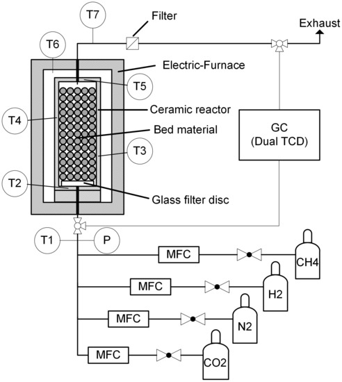
Figure 1.
Schematic representation of the experimental setup.
2.2. Experimental Procedure
In advance of each measurement, the reactor was flushed with inert gas. Due to the discontinuous measurement of the GC, the gas composition was measured within an interval of at least . Therefore, a partial gas flow was continuously branched and supplied to the sample loop of the GC. In each experiment, six GC measurements at the outlet and two measurements at the inlet were taken. The measurements at the inlet were conducted to reduce uncertainties regarding the gas supply and to be capable to calculate the methane and carbon dioxide conversion by the relative change in composition. Thus, additional uncertainties due to the calibration of the GC were reduced. All experiments were conducted at ambient pressure; the temperature was varied from 1250 to . The upper temperature was limited by the maximum operation temperature of the electrical furnace, which was for short-term measurements and for long-term measurements. Additionally, the gas composition and the residence time were varied. A total gas flow rate of 0.03–1 ( volume in liters at and 101,325 ) was used, which resulted in a residence time of approximately 350–10 . The variation of the total gas flow was conducted for pure methane and methane diluted in nitrogen. The amounts of hydrogen and carbon dioxide were varied in a gas mixture which contained methane. A constant flow rate of was applied. The maximum gas flow rate of was chosen to obtain a residence time of approximately . The methane flow rate was limited by the upper limit of the implemented mass flow controller (). In total 39 experimental runs are presented. Each measurement point is hold constant for , except the measurements with a total flow rate below , which were kept constant for to ensure steady state conditions. After each variation the reactor was regenerated with steam to remove the deposited carbon and to prevent clogging. The supplied steam was diluted in nitrogen, to prevent condensation at the reactor outlet. During the endothermic steam regeneration, carbon monoxide and hydrogen were formed:
In advance of the measurements, the steam regeneration was tested. Figure 2 presents the outer view of the reactor and the view in the inside of the reactor before and after the steam regeneration was conducted. During TDM measurements at and different gas flow rates, carbon was produced at the entire cross section of the bed. After the steam regeneration, the deposited carbon was almost entirely removed. The steam regeneration was terminated if the concentration of carbon monoxide in the product gas vanished. Therefore, a regeneration time of approximately was necessary.
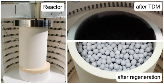
Figure 2.
Outer view of the reactor (left) and view in the reactor: after a thermal decomposition of methane (TDM) measurement at (upper right) and after the steam regeneration (lower right).
The experiments were mainly evaluated by calculating the methane and carbon dioxide conversion :
Especially relevant for the implementation of a methane decomposition process is the amount of hydrogen which is produced from the converted methane. Therefore, the efficiency of hydrogen formation is evaluated by the hydrogen yield: :
If no intermediate products occur in the product, each converted methane molecule produces two hydrogen molecules. According to Equation (5) the hydrogen yield would then be . Intermediates or byproducts would lower the hydrogen yield.
A similar variable is defined to evaluate the carbon dioxide conversion. From the oxygen balance, one molecule of carbon dioxide can produce up to two molecules of carbon monoxide. The carbon produced from the methane decomposition reaction or methane could provide the additional carbon atom. The carbon monoxide yield is defined as follows:
2.3. Experimental Uncertainty
In advance of the TDM measurements, the temperature within the reactor was measured. Therefore, three additional thermocouples were placed in the reactor bed at different heights and different radial positions. A maximum temperature deviation of within the bed was found. Additionally, it was found that the deviation between the average bed temperature and the measured temperature in the reactor walls was always below . Thus, it was suitable to use the temperatures in the reactor walls as the reference temperature. Nevertheless, it has to be mentioned that the local temperature could have been lowered due to the endothermic TDM reaction. At the temperatures evaluated in this study, the uncertainty of the used temperature sensors is given by . The uncertainty of the gas composition measurement is given by the uncertainty of the gas composition of the used calibration gas, and thus the associated uncertainty of the calculated calibration factor. Additionally, a statistical spread of repeated GC measurements is present. Finally, the uncertainty of the massflow controllers is given by the manufacturer ( of measurement and of full scale).
In order to reduce the uncertainties regarding the GC calibration and the supplied gas flows, the methane conversion and the carbon dioxide conversion can be calculated by comparing the GC measurements at the inlet and outlet. The additional inlet measurements allow one to compare the measured peak areas directly. Thus, the conversion can be calculated without using the calibration factor and the supplied gas flows:
is the raw peak area of the measured gas chromatogram. This calculation method is only valid if an additional inert component, in this study nitrogen, is supplied to consider the changed total mole rate. The same method (Equation (7)) is applied to calculate the carbon dioxide conversion. The remaining uncertainty is related to the statistical error in the GC measurements and a possible non-linearity of the TCD sensor. In total, four measurements at the outlet were used to calculate the average compositions and conversions. The standard deviations were used to calculate the error propagation. Maximum absolute uncertainties of percentage points for the methane conversion and percentage points for the carbon dioxide conversion were calculated. Including the uncertainties of the calibration coefficients of the GC, a relative uncertainty of up to for the molar fraction of each component was calculated. The repeatability and validity of the experiments were verified by repeating exemplary experiments after some weeks of operation and several steam regeneration cycles. The calculated methane conversion for the repeated experiments was always within the given uncertainty range. Some of the redundant measurements can be found in the Figure 3, Figure 5 and Figure 7.
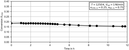
Figure 3.
Methane conversion dependent on of the operation time for methane diluted in nitrogen at .
2.4. Carbon Characterization
The produced carbon was analyzed by Raman spectroscopy using a Bruker Senterra equipped with a ANDOR DU420-OE CCD sensor (Bruker Optik GmbH (Rosenheim, Germany)). The wavelength of the laser line was and the diameter of the laser spot was μm. Five scans with an integration time of each were averaged. The spectra were taken in a scan mode from 100 to 4000 . For each sample the measurements were conducted at least at two positions to confirm the homogeneity of the sample. The laser beam power was set to . In addition to the carbon samples, a reference sample of synthetic graphite with an ash content of <0.3% (manufacturer Chemsys GmbH (Castrop-Rauxel, Germany)) was investigated. All measurements were conducted at room temperature.
3. Experimental Results and Discussion
3.1. Time Evolution of Methane Conversion during TDM
Figure 3 presents the time evolution of the methane conversion after a completed steam regeneration at . The experiment was conducted for a mixture of methane diluted in nitrogen and a flow rate of (corresponds to a residence time of approximately ). During a time period of four hours, the methane conversion remained almost constant, which suggests that the carbon produced in the reactor had no measurable self-catalytic effect. After four hours the methane conversion decreased slightly, and reached at six hours of operation, . After another six hours of operation, the methane conversion was reduced further to . A possible explanation for the slight decrease could be a reduced residence time due to the increasing amount of carbon and thus a reduced porosity in the reactor.
3.2. Flow Rate and Temperature Variation
Figure 4 shows the methane conversion for the variation of the total flow rate at for pure methane and for a mixture of methane diluted in nitrogen. As described in Section 2.3, the experimental uncertainty for the methane conversion is percentage points. Error bars were hardly visible at the scale of the figures and were therefore omitted. The for pure methane is limited by the maximum value of the used methane mass flow controller (), and therefore the gas flow is reduced further. Due to the increasing residence time with decreasing flow rates, the methane conversion increases for lower flow rates. A maximum methane conversion of was obtained at for pure methane. The lowest methane conversion was obtained at . If pure methane is supplied, the methane conversion is below the methane conversion of the methane/nitrogen mixture for equal flow rates. However, the overall reaction rate is higher. The higher reaction rate is related to the larger methane concentration at the inlet. In Table 1 the overall reaction rate and the average methane concentrations in the reactor are given for three flow rates and both methane inlet concentrations. The average methane concentrations were calculated by recalculating the experimental results with a plug flow reactor model. Based on a simple and commonly used kinetic approach for the global reaction [30]:
the reaction order can be approximated. By comparing the experimental results for pure methane and methane diluted in nitrogen, the reaction order becomes . This is in line with the literature, where typically, values of 1 are used for the methane decomposition reaction [23].
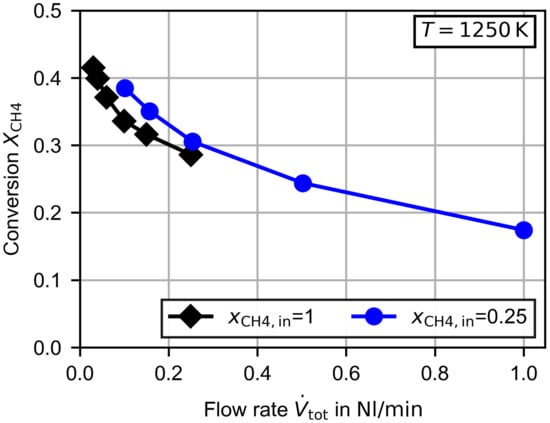
Figure 4.
Measured methane conversion dependent on the total flow rate for pure methane and methane diluted in nitrogen at .

Table 1.
Overall reaction rates and average molar concentrations for the experiments presented in Figure 4. The molar concentrations were calculated by recalculating the experiments with a plug flow reactor model.
In Figure 5a the already presented measurement at is compared to a measurement at . As expected, the methane conversion increased significantly with increasing temperature. At the highest gas flow rate the methane conversion was nearly doubled by the temperature increase of . The general courses of both curves dependent on the gas flow rate are very similar. During the measurements, acetylene (Figure 5b) and ethylene (Figure 5c) were detected as byproducts. In the above-discussed measurements with pure methane, a very small amount of ethane was detected as well (), but in the measurements with the methane/nitrogen mixture, the amount was probably below the detection level of the GC. In the condensate trap at the exhaust, additional undetectable long-chain hydrocarbons seemed to be present.
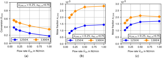
Figure 5.
Experimental results for the TDM dependent on the flow rate at and . (a) Methane conversion, (b) molar fraction of acetylene and (c) molar fraction of ethylene.
As can be seen in Figure 5b, the amount of acetylene increased with increasing temperature and increasing gas flow rate. This behavior was also observed for ethylene at . At , the molar fraction increased slightly for a decreasing gas flow rate until it reached a maximum. Finally, the amount of ethylene decreased with a decreasing gas flow rate. In the TDM measurements presented by Billaud et al. [31], which were conducted at in an empty alumina reactor, acetylene and ethylene were also the byproducts in the largest amounts. Billaud et al. varied the residence time for pure methane from below to . At a residence time of about of the byproducts were acetylene and ethylene. In total, the molar fraction of byproducts was found to be . Goehler et al. [32] presents TDM measurements in a packed bed reactor (filled with coke) at and residence times from about to . At a residence time above the molar fraction of the cumulative amount of acetylene, ethylene and benzene was 0.010–0.014. In order to compare these results with this study, nitrogen was neglected for the calculation of the byproduct molar fraction. At the lowest residence time in this study (about at ), the molar fraction of the byproducts becomes 0.012–0.016, which is in line with the literature.
The total amount of byproducts reduced the hydrogen yield, which is presented together with the methane conversion in Figure 6 for three investigated temperatures. The given error bars are related to the uncertainties of the gas composition measurement (calibration and standard deviation of averaged measurements) and the following error propagation for the calculation of . An increasing temperature increased the hydrogen yield by up to at . At first glance, this behavior is counterintuitive to the increasing amount of byproducts with increasing temperature (see Figure 5), but the hydrogen yield is related to the amount of byproducts due to the amount of reacted methane. The methane conversion increased from at to at , and thus in total an increasing hydrogen yield was obtained.
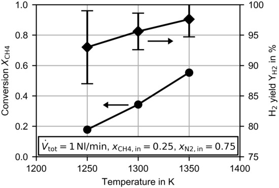
Figure 6.
Methane conversion and hydrogen yield dependent on of the temperature at a constant flow rate of .
3.3. Hydrogen and Carbon Dioxide Variation
In the following, all presented measurements were conducted with a constant flow rate of and a methane mole fraction of . The amount of nitrogen was varied depending on the amount of carbon dioxide or hydrogen in the feed. Carbon dioxide is present at up to in natural gas [33] and at up to in biomethane [27]. In this study carbon dioxide was added by up to a tenth per mole of the supplied methane flow. Additional hydrogen could be in the reactor feed if, at system level, gas recycling was implemented [26]. This was simulated by adding hydrogen at up to a fourth per mole of the methane flow. If carbon dioxide is added to such a feed, the set of possible reactions is enlarged, and the hydrogen production could be influenced. In accordance to the reactions which could occur during non-catalytic -reforming [34], the additional global reactions might be the Boudouard, the reverse water gas shift, the -reforming and the methane steam reforming reaction:
Figure 7 presents the variation of carbon dioxide. The / ratio at the first measurement point with carbon dioxide in the feed was similar to the ratio found in biomethane [27]. As can be seen in Figure 7a at , the methane conversion remained almost constant, but at the methane conversion increased slightly with an increasing amount of carbon dioxide. For both temperatures the carbon dioxide conversion decreased with an increasing amount of carbon dioxide in the feed. The increase in temperature increased the carbon dioxide conversion to a similar extent as the methane conversion. As there was no increase in the methane conversion at , the most reasonable reaction pathway for carbon dioxide was the reverse water gas shift (rWGS (10)) or the Boudouard reaction (9). The decreasing carbon dioxide conversion could have been due to an inhibition effect of the carbon monoxide, which is especially observed for the Boudouard reaction (9) [35], or a reaction order with respect to carbon dioxide of less than one. The increasing methane conversion at could have been a product of an accelerated -reforming reaction (11). Zhang et al. [34] reports for non-catalytic conditions a beginning -reforming at a temperature of , which increases rapidly for higher temperatures.
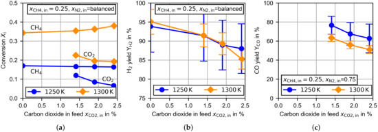
Figure 7.
Experimental results for the TDM dependent on the molar fraction of carbon dioxide in the feed at and at a constant flow rate of . (a) Methane/carbon dioxide conversion, (b) hydrogen yield and (c) carbon monoxide yield.
In Figure 7b the hydrogen yield is presented. For both temperatures, the magnitude and shape of the curves are very similar. For the pure TDM measurements at the hydrogen yield was close to . Considering the hydrogen bounded in the byproducts given in Figure 5b,c, the hydrogen yield was larger than , which suggests that the main byproducts were detected. An increasing amount of carbon dioxide in the feed leads to a decreasing hydrogen yield. This is partly related to slightly increasing amounts of acetylene and ethylene, but the hydrogen balance reveals that additional byproducts have to be present. The decreasing hydrogen production could have been a result of an increasing progress in the rWGS reaction, which consumes hydrogen, or the formation of other not-detectable byproducts.
The probability of an increasing progress in the rWGS reaction can be predicted by evaluating the carbon monoxide yield. If carbon dioxide is mainly consumed by the Boudouard reaction or the -reforming, tends to . In contrast, a predominant rWGS reaction would lead to a carbon monoxide yield close to . If the produced water reacts by methane steam reforming (12) or in the gasification of deposited carbon (2), would rise again. As can be seen in Figure 7c, decreases with an increase in temperature or in the amount of carbon dioxide in the feed. At and larger carbon dioxide feed concentrations especially, the carbon monoxide yield tended to . This is an indication of increasing relevance of the rWGS reaction.
Finally, Figure 8 presents the variations of carbon dioxide and hydrogen in the feed. The measurements were conducted at . In part (a) of the Figure 8, the methane and carbon dioxide conversion is shown. Even without carbon dioxide in the feed stream, the methane conversion decreased with an increasing amount of hydrogen. A retarded methane decomposition in the presence of larger hydrogen partial pressures was also described by Kassel [19] for lower operation temperatures, but was not confirmed by Skinner et al. [20] at temperatures above the temperatures in this study. Despite the decreased methane conversion, the average hydrogen molar fraction in the reactor was increased by for the hydrogen inlet fraction of and by for . To a reduced extent, increasing methane conversion with an increasing amount of carbon dioxide was also observed for the measurements with hydrogen in the feed stream. The carbon dioxide conversion increased significantly through the addition of hydrogen. This was especially the case for low concentrations of carbon dioxide. According to the discussion above, the most reasonable explanation is the acceleration of the rWGS reaction. The high sensitivity regarding the hydrogen partial pressure supports this suspicion, as the reaction rate of the rWGS reaction increases with an increasing hydrogen partial pressure [36].
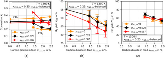
Figure 8.
Experimental results for the TDM dependent on the molar fractions of hydrogen and carbon dioxide in the feed at at a constant flow rate of . (a) Methane/carbon dioxide conversion, (b) hydrogen yield and (c) carbon monoxide yield.
The hydrogen yield, presented in Figure 8b, was slightly reduced for the largest amount of hydrogen in the feed stream. The general trend of a decreasing for larger carbon dioxide concentrations was observed for each hydrogen feed concentration. The carbon monoxide yield was not clearly affected by the amount of hydrogen in the feed stream (see Figure 8c).
3.4. Carbon Characterization
During the TDM measurements, the majority of the carbon produced was deposited on the ceramic bed material, but also in the void between the bed material. From optical microscopy images, it was revealed that the carbon in the void was deposited as fibers with a diameter of 1–2 μ. The fibers begin to grow on the surface of the already deposited carbon on the bed material. As shown in Figure 2, carbon is deposited at the entire cross section of the reactor. Qualitatively a homogeneous distribution of the deposited carbon is obtained, which suggests a homogeneous gas distribution and homogeneous reaction temperature. The formation of fibers on top of carbon covered bed material is mostly observed for metal catalyzed TDM [37] but also for carbon catalyzed TDM [38]. While the formation mechanism of carbon fibers in metal catalyzed TDM is well described, the fiber formation mechanism for carbon catalyzed TDM is not fully understood. To the best of the knowledge of the authors, the formation of carbon fibers in non-catalytic TDM has not even been reported yet. This observation could be connected to the investigation of large residence times, which are typically not in the parameter range of other studies in the literature. In order to investigate the microstructure of the carbon qualitatively, Raman spectroscopy measurements were conducted. In the literature for non-catalytic TDM at temperatures similar to this study, graphitic films are reported to be deposited carbon type [39]. Therefore, commercial graphite was analyzed as a reference. The carbon samples were produced during TDM measurements at and varying gas flow rates of pure methane.
In Figure 9 images of the produced carbon and the associated Raman spectra are given. As is well known from the literature that graphite has a characteristic line at also called the G band. Additionally, a line appeared at approximately , which is related to disorder or defects in the sample (D band), and its overtone at (D* band) occurs [40]. Unlike graphite, the carbon samples were characterized by a high intensity D band and a less intense G band. The intensity of the D* band was also reduced, but another small line at occurred. Despite the different macroscopic appearances of the samples, the Raman spectra of the carbon samples are very similar, which suggests that the microscopic structure did not differ greatly. In conclusion, the carbon samples had a highly disordered microstructure. Qualitatively, the Raman spectra of the samples are similar to those observed after longer operations of TDM in combination with different carbon catalysts [41].
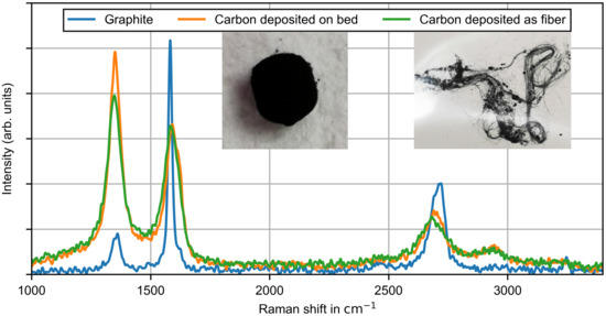
Figure 9.
Raman intensity plots of carbon samples deposited on the ceramic bed material and in the void space as fibers. Carbon samples were produced during a thermal decomposition measurement at and varying gas flow rates of pure methane.
4. Conclusions
The non-catalytic thermal decomposition of methane was experimentally studied in a temperature range of 1250–1350 for varying residence times and feed gas compositions. Experiments were conducted in a packed continuous flow reactor composed of aluminum oxide ceramic. The carbon produced was mainly deposited on the bed material, but also in the void as fibers with a thickness of up to μm. During a continuous experiment of six hours, no self catalytic effect was observed. Raman spectroscopy measurements of the produced carbon revealed a highly disordered mircostructure.
The observed methane conversion was up to at a hydrogen yield of up to . Acetylene and ethylene were found to be the main byproducts. If small amounts of carbon dioxide were added (up to a tenth of the amount of methane supplied) the hydrogen yield dropped down by up to ten percentage points. The carbon dioxide conversion increased with an increasing temperature and decreased for increasing amounts of carbon dioxide. At the methane conversion remained almost constant, but at a slight increase was observed, which was probably related to an increasing reaction rate of the -reforming reaction. The yield of carbon monoxide tended toward with increasing temperature and carbon dioxide. This suggests that the reverse water gas shift reaction occurs. Hydrogen has an inhibiting effect on the methane decomposition reaction. Additionally, the carbon dioxide conversion was increased, which also supports the occurrence of the reverse water gas shift reaction. The observed carbon dioxide conversion was up to .
The large decrease of the hydrogen yield due to carbon dioxide in the feed suggests that the amount of carbon dioxide in the feedstock should be reduced as much as possible. Otherwise, it should be taken into account during the plant design. Therefore, a kinetic model considering the main global reactions must be created. Based on the experimental results, the Boudouard reaction, the reverse water gas shift reaction and at temperatures above , the -reforming reaction are expected to play important roles.
Author Contributions
Conceptualization, T.M.; methodology, T.M.; software, T.M.; formal analysis, T.M. and S.W.; investigation, T.M. and S.W.; writing–original draft preparation, T.M.; writing–review and editing, T.M. and S.K.; visualization, T.M.; supervision, S.K. All authors have read and agreed to the published version of the manuscript.
Funding
This research received no external funding.
Acknowledgments
The authors gratefully acknowledge Claus Rüscher for conducting the Raman spectroscopy measurements. The Deutsche Forschungsgemeinschaft (DFG) provided the majority of the experimental setup for the thermal decomposition measurements as part of the major research instrumentation program with contract number INST 187/630-1 FUGG. The publication of this article was funded by the Open Access Fund of the Leibniz University Hannover.
Conflicts of Interest
The authors declare no conflict of interest.
References
- Ewan, B.C.R.; Allen, R.W.K. A figure of merit assessment of the routes to hydrogen. Int. J. Hydrog. Energy 2005, 30, 809–819. [Google Scholar] [CrossRef]
- Gibbins, J.; Chalmers, H. Carbon capture and storage. Energy Policy 2008, 36, 4317–4322. [Google Scholar] [CrossRef]
- Mueller-Langer, F.; Tzimas, E.; Kaltschmitt, M.; Peteves, S. Techno-economic assessment of hydrogen production processes for the hydrogen economy for the short and medium term. Int. J. Hydrog. Energy 2007, 32, 3797–3810. [Google Scholar] [CrossRef]
- Gahleitner, G. Hydrogen from renewable electricity: An international review of power-to-gas pilot plants for stationary applications. Int. J. Hydrog. Energy 2013, 38, 2039–2061. [Google Scholar] [CrossRef]
- Ursúa, A.; Gandía, L.M.; Sanchis, P. Hydrogen production from water electrolysis: Current status and future trends. Proc. IEEE 2012, 100, 410–426. [Google Scholar] [CrossRef]
- Machhammer, O.; Bode, A.; Hormuth, W. Financial and Ecological Evaluation of Hydrogen Production Processes on Large Scale. Chem. Eng. Technol. 2016, 39, 1185–1193. [Google Scholar] [CrossRef]
- Keipi, T.; Tolvanen, H.; Konttinen, J. Economic analysis of hydrogen production by methane thermal decomposition: Comparison to competing technologies. Energy Convers. Manag. 2018, 159, 264–273. [Google Scholar] [CrossRef]
- Parkinson, B.; Matthews, J.W.; McConnaughy, T.B.; Upham, D.C.; McFarland, E.W. Techno-Economic Analysis of Methane Pyrolysis in Molten Metals: Decarbonizing Natural Gas. Chem. Eng. Technol. 2017, 40, 1022–1030. [Google Scholar] [CrossRef]
- Abbas, H.F.; Wan Daud, W.M.A. Hydrogen production by methane decomposition: A review. Int. J. Hydrog. Energy 2010, 35, 1160–1190. [Google Scholar] [CrossRef]
- Guil-Lopez, R.; Botas, J.A.; Fierro, J.L.G.; Serrano, D.P. Comparison of metal and carbon catalysts for hydrogen production by methane decomposition. Appl. Catal. A Gen. 2011, 396, 40–51. [Google Scholar] [CrossRef]
- Łamacz, A.; Łabojko, G. CNT and H2 production during CH4 decomposition over Ni/CeZrO2. II. catalyst performance and its regeneration in a fluidized bed. ChemEngineering 2019, 3, 25. [Google Scholar] [CrossRef]
- Muradov, N.; Chen, Z.; Smith, F. Fossil hydrogen with reduced CO2 emission: Modeling thermocatalytic decomposition of methane in a fluidized bed of carbon particles. Int. J. Hydrog. Energy 2005, 30, 1149–1158. [Google Scholar] [CrossRef]
- Serrano, D.P.; Botas, J.A.; Guil-Lopez, R. H2 production from methane pyrolysis over commercial carbon catalysts: Kinetic and deactivation study. Int. J. Hydrog. Energy 2009, 34, 4488–4494. [Google Scholar] [CrossRef]
- Serrano, D.P.; Botas, J.A.; Pizarro, P.; Gómez, G. Kinetic and autocatalytic effects during the hydrogen production by methane decomposition over carbonaceous catalysts. Int. J. Hydrog. Energy 2013, 38, 5671–5683. [Google Scholar] [CrossRef]
- Muradov, N. Hydrogen via methane decomposition: An application for decarbonization of fossil fuels. Int. J. Hydrog. Energy 2001, 26, 1165–1175. [Google Scholar] [CrossRef]
- Rodat, S.; Abanades, S.; Grivei, E.; Patrianakos, G.; Zygogianni, A.; Konstandopoulos, A.G.; Flamant, G. Characterisation of carbon blacks produced by solar thermal dissociation of methane. Carbon 2011, 49, 3084–3091. [Google Scholar] [CrossRef]
- Gautier, M.; Rohani, V.; Fulcheri, L. Direct decarbonization of methane by thermal plasma for the production of hydrogen and high value-added carbon black. Int. J. Hydrog. Energy 2017, 42, 28140–28156. [Google Scholar] [CrossRef]
- Kheirollahivash, M.; Rashidi, F.; Moshrefi, M. Hydrogen Production from Methane Decomposition Using a Mobile and Elongating Arc Plasma Reactor. Plasma Chem. Plasma Process. 2019, 39, 445–459. [Google Scholar] [CrossRef]
- Kassel, L.S. The thermal decomposition of methane. J. Am. Chem. Soc. 1932, 54, 3949–3961. [Google Scholar] [CrossRef]
- Skinner, G.B.; Ruehrwein, R.A. Shock tube studies on the pyrolysis and oxidation of methane. J. Phys. Chem. 1959, 63, 1736–1742. [Google Scholar] [CrossRef]
- Rodat, S.; Abanades, S.; Coulié, J.; Flamant, G. Kinetic modelling of methane decomposition in a tubular solar reactor. Chem. Eng. J. 2009, 146, 120–127. [Google Scholar] [CrossRef]
- Abánades, A.; Ruiz, E.; Ferruelo, E.M.; Hernández, F.; Cabanillas, A.; Martínez-Val, J.M.; Rubio, J.A.; López, C.; Gavela, R.; Barrera, G.; et al. Experimental analysis of direct thermal methane cracking. Int. J. Hydrog. Energy 2011, 36, 12877–12886. [Google Scholar] [CrossRef]
- Keipi, T.; Li, T.; Løvås, T.; Tolvanen, H.; Konttinen, J. Methane thermal decomposition in regenerative heat exchanger reactor: Experimental and modeling study. Energy 2017, 135, 823–832. [Google Scholar] [CrossRef]
- Fau, G.; Gascoin, N.; Steelant, J. Hydrocarbon pyrolysis with a methane focus: A review on the catalytic effect and the coke production. J. Anal. Appl. Pyrolysis 2014, 108, 1–11. [Google Scholar] [CrossRef]
- Munera Parra, A.A.; Platte, F.; Agar, D.W. Multiplicity Regions in a Moving-Bed Reactor: Bifurcation Analysis, Model Extension, and Application for the High-Temperature Pyrolysis of Methane. Chem. Ing. Tech. 2016, 88, 1703–1714. [Google Scholar] [CrossRef]
- Marquardt, T.; Bode, A.; Kabelac, S. Hydrogen production by methane decomposition: Analysis of thermodynamic carbon properties and process evaluation. Energy Convers. Manag. 2020, 221. [Google Scholar] [CrossRef]
- Strauch, S.; Krassowski, J.; Singhal, A. Biomethane Guide for Decision Makers—Policy Guide on Biogas Injection Into the Natural Gas Grid; Technical Report; Frauenhofer UMSICHT: Oberhausen, Germany, 2013. [Google Scholar]
- International Organization for Standardization. ISO 14687:2019: Hydrogen Fuel Quality—Product Specification; International Organization for Standardization: Geneva, Switzerland, 2019. [Google Scholar]
- Lee, S.Y.; Ryu, B.H.; Han, G.Y.; Lee, T.J.; Yoon, K.J. Catalytic characteristics of specialty carbon blacks in decomposition of methane for hydrogen production. Carbon 2008, 46, 1978–1986. [Google Scholar] [CrossRef]
- Plevan, M.; Geißler, T.; Abánades, A.; Mehravaran, K.; Rathnam, R.K.; Rubbia, C.; Salmieri, D.; Stoppel, L.; Stückrad, S.; Wetzel, T. Thermal cracking of methane in a liquid metal bubble column reactor: Experiments and kinetic analysis. Int. J. Hydrog. Energy 2015, 40, 8020–8033. [Google Scholar] [CrossRef]
- Billaud, F.; Gueret, C.; Weill, J. Thermal decomposition of pure methane at 1263 K. Experiments and mechanistic modelling. Thermochim. Acta 1992, 211, 303–322. [Google Scholar] [CrossRef]
- Goehler, P.; Hastorok, W.; Mehnert, E. Beitrag zur Kinetik der Thermischen Methanspaltung; Technical Report; Brenntoffinstitut Freiberg: Dresden, Germany, 1974. [Google Scholar]
- OGE. Erdgas-Orientierungswerte 2019. Available online: https://oge.net/de/ (accessed on 7 February 2021).
- Zhang, G.; Qu, J.; Su, A.; Zhang, Y.; Xu, Y. Towards understanding the carbon catalyzed CO2 reforming of methane to syngas. J. Ind. Eng. Chem. 2015, 21, 311–317. [Google Scholar] [CrossRef][Green Version]
- Lahijani, P.; Zainal, Z.A.; Mohammadi, M.; Mohamed, A.R. Conversion of the greenhouse gas CO2 to the fuel gas CO via the Boudouard reaction: A review. Renew. Sustain. Energy Rev. 2015, 41, 615–632. [Google Scholar] [CrossRef]
- Bustamante, F.; Enick, R.M.; Cugini, A.V.; Killmeyer, R.P.; Howard, B.H.; Rothenberger, K.S.; Ciocco, M.V.; Morreale, B.D.; Chattopadhyay, S.; Shi, S. High-Temperature Kinetics of the Homogeneous Reverse Water-Gas Shift Reaction. AICHE J 2004, 50, 1028–1041. [Google Scholar] [CrossRef]
- Amin, A.M.; Croiset, E.; Epling, W. Review of methane catalytic cracking for hydrogen production. Int. J. Hydrog. Energy 2011, 36, 2904–2935. [Google Scholar] [CrossRef]
- Wang, J.; Jin, L.; Zhou, Y.; Li, Y.; Hu, H. Effect of Ca(NO3)2 addition in coal on properties of activated carbon for methane decomposition to hydrogen. Fuel Process. Technol. 2018, 176, 85–90. [Google Scholar] [CrossRef]
- Shah, N.; Panjala, D.; Huffman, G.P. Hydrogen production by catalytic decomposition of methane. Energy Fuels 2001, 15, 1528–1534. [Google Scholar] [CrossRef]
- Reich, S.; Thomson, C. Raman spectroscopy of graphite. Philos. Trans. R. Soc. A 2004, 362, 2271–2288. [Google Scholar] [CrossRef] [PubMed]
- Nishii, H.; Miyamoto, D.; Umeda, Y.; Hamaguchi, H.; Suzuki, M.; Tanimoto, T.; Harigai, T.; Takikawa, H.; Suda, Y. Catalytic activity of several carbons with different structures for methane decomposition and by-produced carbons. Appl. Surf. Sci. 2019, 473, 291–297. [Google Scholar] [CrossRef]
Publisher’s Note: MDPI stays neutral with regard to jurisdictional claims in published maps and institutional affiliations. |
© 2021 by the authors. Licensee MDPI, Basel, Switzerland. This article is an open access article distributed under the terms and conditions of the Creative Commons Attribution (CC BY) license (http://creativecommons.org/licenses/by/4.0/).