Article

Ion-Liquid Based Supercapacitors with Inner Gate Diode-Like Separators

Electrical and Computer Engineering and Electronic Imaging Center, New Jersey Institute of Technology, Newark, NJ 07102, USA
*
Author to whom correspondence should be addressed.
ChemEngineering 2019, 3(2), 39; https://doi.org/10.3390/chemengineering3020039
Submission received: 11 March 2019 / Revised: 6 April 2019 / Accepted: 9 April 2019 / Published: 14 April 2019
(This article belongs to the Special Issue Advanced Functional Low-dimensional Materials and Their Applications)

Abstract

:
In order to minimize unintentional discharge, supercapacitors are interfaced with a membrane that separates the anode from the cathode—this membrane is called the separator. We focus here on separators, which are structured as electronic diode-like. We call an electrically structured separator “the gate”. Through experiments, it was demonstrated that ionic liquid-filled supercapacitors, which were interfaced with gated separators exhibited a substantial capacitance (C) increase and reduction in the equivalent series resistance (ESR) compared to cells with ordinary separators. These two attributes help to increase the energy, which is stored in a cell, since for a given cell’s voltage, the dissipated energy on the cell, UR = V2/4(ESR) and the stored energy, UC = CV2/2, would increase. These were indeed ionic diodes since the order of the diode layout mattered—the diode-like structures exhibited maximum capacitance when their p-side faced the auxiliary electrode.

Graphical Abstract

1. Introduction

Increasingly, supercapacitors find more and more applications in short-term energy storage [1,2,3,4,5,6], namely, energy elements that can quickly handle substantial amount of current. A supercapacitor is made of two electrodes: The anode and the cathode. Both electrodes are immersed in an electrolyte. A separator membrane between the electrodes (Figure 1a) was introduced to minimize unintentional electrical discharge. Thus far, research on increasing cells capacitance with carbon materials has been focused on increasing the surface area of the electrodes, decreasing the effective charge separation at the electrode-electrolyte interface, and, in some cases, on increasing the efficiency of charge transfer [7,8,9,10,11,12,13,14,15]. We have opted to study the less researched, yet equally important separator layer. We modified the otherwise electrically insulating or unbiased membrane [16,17,18,19,20] into a capacitive, diode-like, or even transistor-like porous structure [21,22,23,24,25].
The general idea was to place a permeable potential barrier between the anode and the cathode. The diode-like element was an ion porous structure. It was formed by layering doped films, in our case p-type and n-type layers of functionalized single-walled carbon nanotubes (SWCNTs). We call this electronically structured element “the gate”.
When an ordinary supercapacitor is charged, the potential distribution is constant throughout most of its regions, with the exception of the electrolyte-electrode interfaces. This is due to a screening effect by the ions, in response to excess electronic charge on the electrodes. In our case, the electrolyte filled the space within and outside the SWCNTs. Due to the lack of charge transfer between the electrolyte and SWCNTs, the ions in the liquid screened the local electronic charges at the diode-like gate. The result was ion charge separation. Ion charge separation led to polarity increase in the mid-cell region (Figure 1b,c) and might be viewed as a capacitor (the gate) within another (the supercapacitor). A capacitor-within-capacitor (CWC) has been shown to increase the overall capacitance of capacitors [26]. The concept is general and may be easily incorporated into existing supercapacitor structures.
Specifically, our diode-like separators were made of two layers, each composed of functionalized SWCNT film. One layer was composed of electronically p-type tubes, and the other layer was composed of electronically n-type tubes. The SWCNTs may be viewed as nano-cylinders that form a nano-contact [27,28]. An interface (for example, when one layer is deposited on top of another or when two such layers are pressed together) is composed of numerous such nano-contacts. The interface behaved as an effective diode (Figure 3). The diode-like structure was permeable to ions and exhibited resistance and capacitance, as evidenced by the various electrochemical techniques described below.

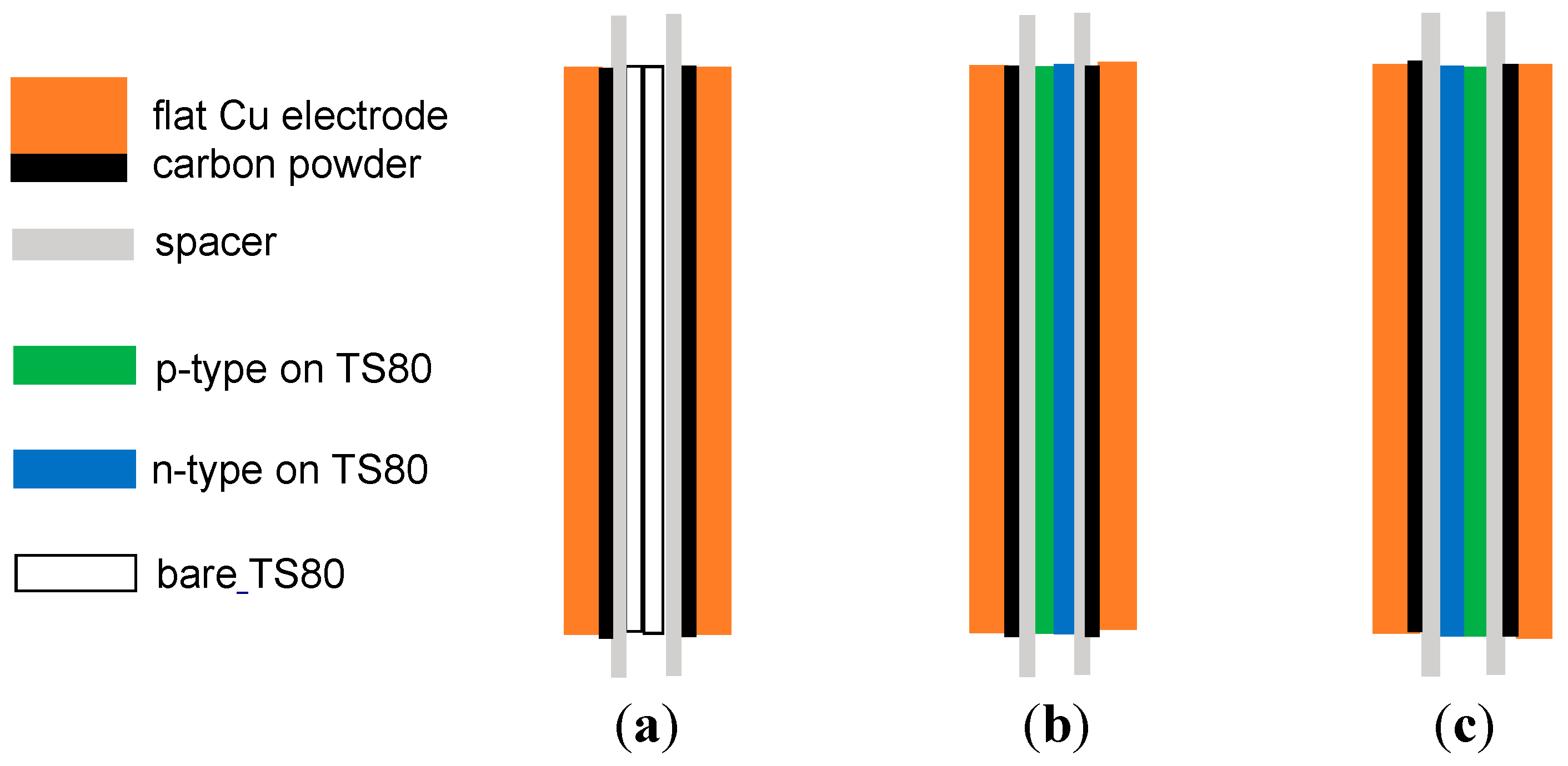
2. Experiment and Methods

Single wall carbon nanotubes (SWCNTs) were obtained from Nano Integris, Canada, with certified purity of better than 95%. The average tube diameter was 1.4 nm, with an average length of 1 micron. The SWCNTs may be purchased with little metallic catalyst content (<1%). The remaining ca. 4% was inert carbonaceous material. The SWCNTs were functionalized with polymers—doping of either the p-type, or the n-type tubes was achieved by wrapping them with polyvinyl pyrrolidone (PVP) and polyethylenimine (PEI), respectively [29,30]. The surface area of the functionalized tubes may be estimated as follows: the total thickness of a wrapped tube is considered as a bundle of 20 tubes. Taking into account the larger molecular weight of the wrapping polymer, we estimated that the surface area of PVP and PEI wrapped tubes was 15 and 7.5 m2/g, respectively. After that, the p-type and n-type nanotubes were suspended in deionized (DI) water using a horn probe sonicator for 8 hours. Using vacuum, each layer was then drop-casted on a hydrophilic filter (TS80, TriSep). The thickness of each SWCNT-type layer was estimated at less than 10 μm, microns by weight and covered area. In this study and previous experiments, we found that the polymer wrapping process and sonication substantially reduced the undesired material content (non-semiconducting tubes and other carbonaceous material) in the sample, thus eliminating the need for refluxing. Due to the relatively small bandgap at the p-n interface [27] and the relatively light doping of the tubes, the depletion region extended throughout the entire gate’s cross-section. As shown in Figure 2, some of the SWCNT form bundles, which did not affect the electrical properties under dry conditions (Figure 3a,b). The quality of the diode-like structure was also ascertained by a current-voltage trace, as shown in Figure 3. We comment on the performance of the diode-like gate under wet conditions in the Conclusion Section.
In the following, we show that the gate was composed of p-type and n-type films. Current-voltage (I-V) measurements were conducted on each SWCNT-type film (Figure 3a) under dry conditions. A single-type film behaved as a resistor, exhibiting a linear curve. The resistance of each layer was dictated by the SWCNT doping, and Figure 3a alludes to the larger conductivity of the p-type layer. Since the SWCNTs are naturally p-type even without the wrapping by PVP, wrapping by PEI to turn them into n-type is not optimal. Hence, the n-type film would be expected to exhibit higher resistance. Linearity and symmetry in the −1, +1 V window also alludes to the ohmic contact to the samples. The I-V curve for a diode-like structure behaves nonlinearly with an accelerated behavior in a forward direction (namely, when the positive lead is on the p-type film and the negative lead on the n-type side).
In Figure 4 we show the Raman spectra for each doped film. Both films exhibited a similar G+ line at 1616 cm−1. The broadened G line’s position was affected by the tube’s doping: the n-type film exhibited a downshift of ca. 10 cm−1 due to its negative doping with respect to the p-type film. A 3 mW HeNe laser at 633 nm was used in conjunction with a 75 cm spectrometer and a charge coupled device (CCD) array, which was cooled to −35 °C. The spectral resolution was 1 cm−1.
Thermoelectric data are provided in Table 1 for each single-type film. The potential difference when the sample is resting between a heated end (maintained at a given temperature of a hot plate) and a cold end (maintained at room temperature) is shown. The positive lead of the multimeter was placed on the hot end. The data corroborated the doping type of the SWCNT, namely, negative values for a p-type film and positive values for an n-type film. The data also alluded to the larger p-type doping.
Ionic liquid, 1-n-Butyl-3-methyl-imidazolium hexafluorophosphate, was used as an electrolyte. It has been previously used in related experiments [26]. It does not react with carbon species, has little reaction with the copper electrodes, and has a relatively large potential window. It filled the space between two 25-micron-thick flat copper (Cu) electrodes, of size 5 × 3 cm2 each. The ionic liquid soaked 0.1 mm thick lens tissues (Bausch & Lomb), which are used here as spacers. The configurations for the cell with and without the gate (namely, using bare insulating TS80 membranes to achieve the same separator thickness) are shown in Figure 5a,b. The assembled sample rested overnight to let the ion-liquid soak in. In order to increase the cell capacitance, modified Cu electrodes (Figure 5c) were prepared by placing a double-sided carbon tape (typically used for SEM samples) on the copper films and spreading 1-micron carbon powder (Alpha) on the tape. Loose powder was shaken off. The thickness of the carbon tape was 100 microns and the thickness of the powder on the tape was estimated at 1 micron by sample weight and surface coverage. The cell was pressed between two 1 mm-thick glass plates to ensure electrode flatness. An example of a measurement procedure was as follows: The cell was first tested with a bare separator. Then, the cell was opened up, interfaced with a structured gate, and tested again. The order of testing (e.g., bare separator second and structured gate first) did not affect the final outcome.

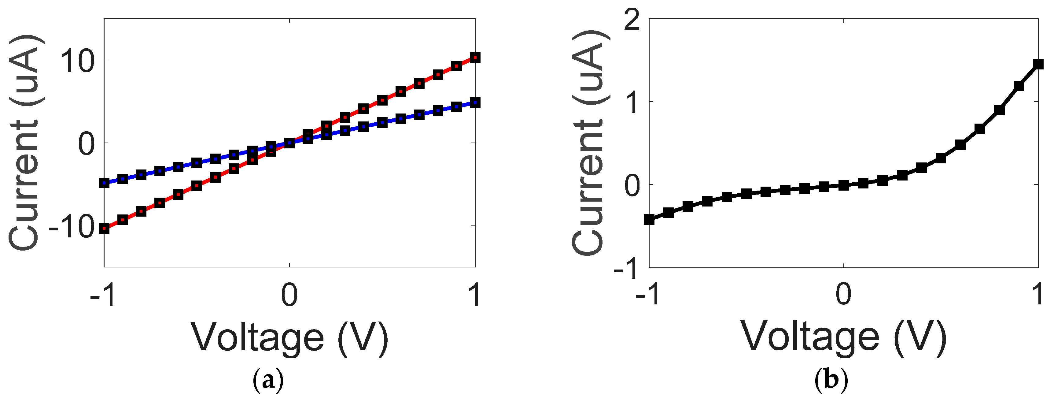
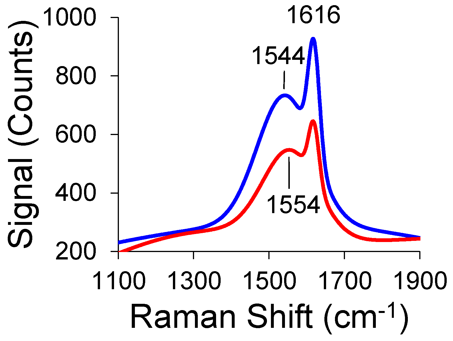
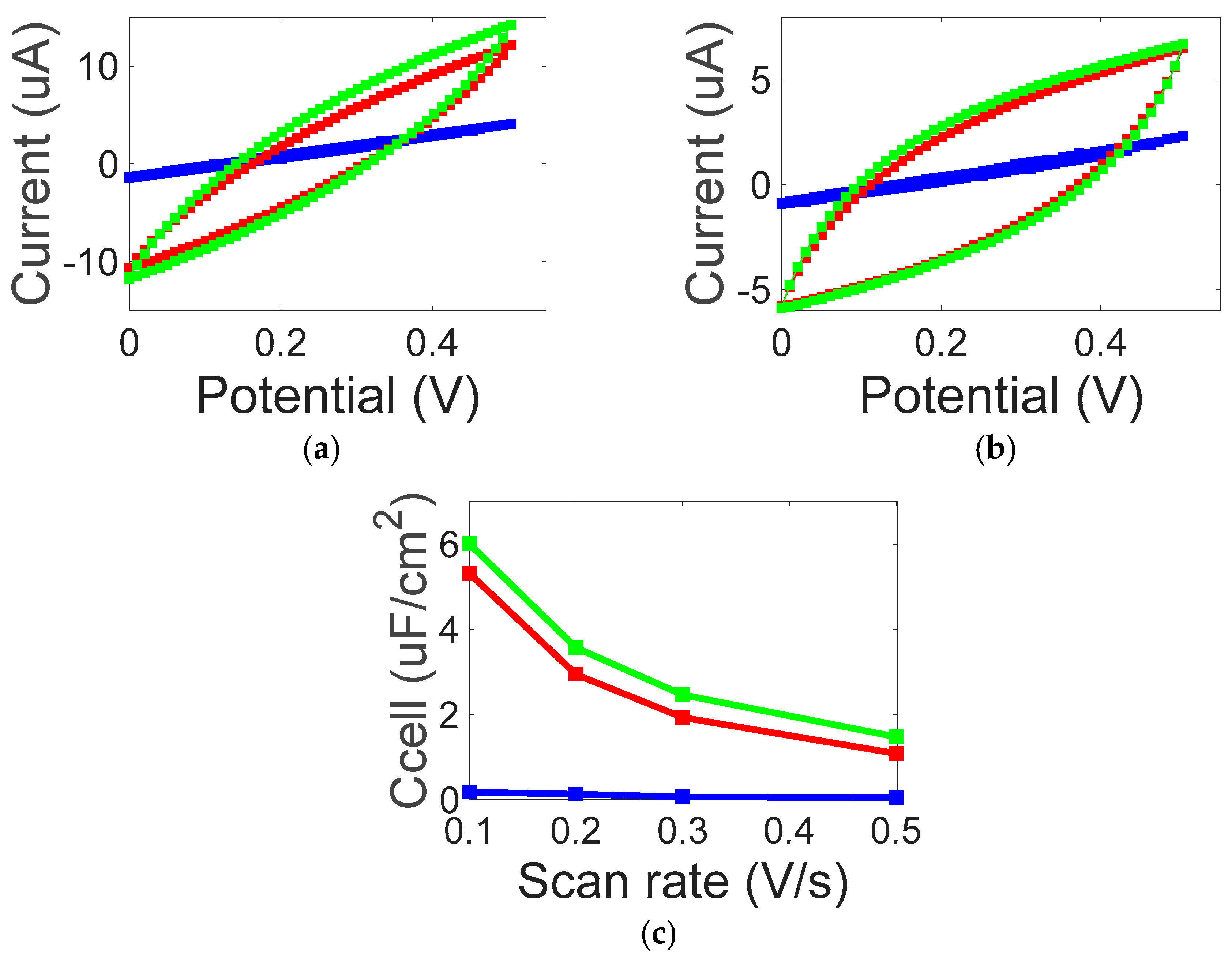
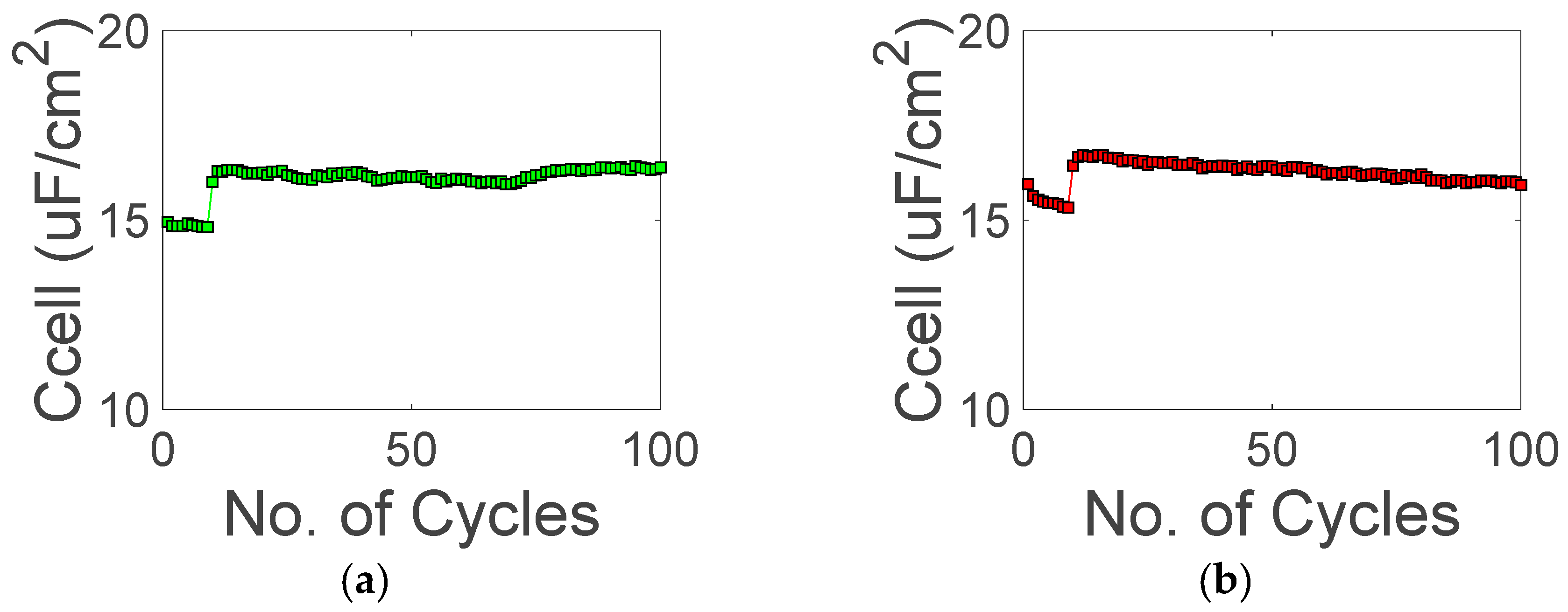
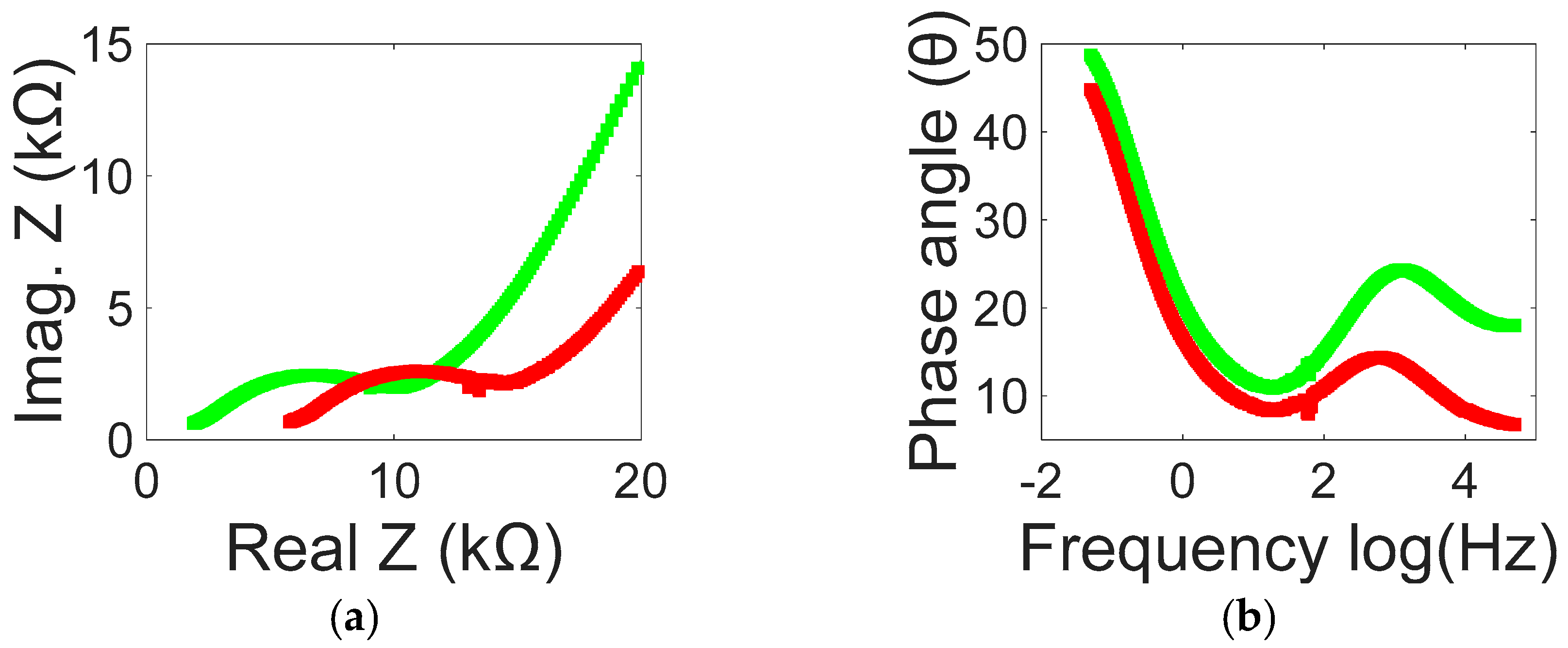
3. Results and Discussion

The 2-electrode Cyclic-Voltammetry (CV) traces and their corresponding capacitance values are shown in Figure 6. While ionic liquid may sustain a relatively large bias, the voltage window was chosen as 0–0.5 V to compare it with an aqueous cell, which is described elsewhere. Since the layout of the structured separator (the gate) is asymmetric upon interchanging it with respect to the position of the auxiliary electrode, one might expect a respective change in the cell’s capacitance, as well. In Figure 6a,b we show the CV traces for two cases: one, where the n-side of the gate faced the auxiliary electrode and the other, where the p-side of the gate faced the auxiliary electrode. The blue trace for the bare separator is barely open, implying a very small cell capacitance. As observed from Figure 6c, the cell’s specific capacitance substantially increased upon replacing the bare separator with the diode-like gate. Maximum capacitance was achieved when the p-side faced the auxiliary electrode.
Stability tests shown in Figure 7 are for 100 CV cycles. The scan rate was relatively small (0.01 V/s), therefore, the obtained capacitance values were enhanced compared to Figure 6c. Stability was reached after the ca. 10th cycle. We postulate that diffusion processes required a few cycles before reaching stability due to the high resistance of the ionic liquid. Thereafter, both configurations appear stable and varied within 2% and 4%, respectively, when either the p-side or the n-side was facing the auxiliary electrode. Diffusion and drift currents also played a role in energy losses: preliminary data (not shown) indicated that cells interfaced with bare membranes exhibited shorter time constants (of ca. 10 sec) than those interfaced with the diode-like gate (of ca. 20 sec).
Electrochemical impedance spectroscopy (EIS) were performed for a frequency range of 50 kHz to 50 MHz with a 10 mV AC perturbation signal. In Figure 8 we compare two cases of gate layout with respect to the auxiliary electrode. The knee frequency was 19 Hz (red) and 14 Hz (green) when the auxiliary electrode faced the n-side and the p-side, respectively. The equivalent series resistance (ESR) for ionic liquid-based cells was quite high and was of the order of tens of kΩ. The smaller ESR value was noted when the p-side was facing the auxiliary electrode. The smaller ESR value for the p-n layout was correlated with the largest overall cell’s capacitance. The results point to the difference in cell impedance between the two gate layouts. This is further proof that the mid-cell gate indeed acts as a diode-like and also points to ionic mid-cell charge separation that leads to an increase in the overall cell capacitance.

4. Conclusions

One can increase the capacitance of supercapacitors by incorporating a diode-like structure (gate) within them. The layout of the diode-like structure is asymmetric with respect to the auxiliary electrode, and, as a result, the measured cell’s capacitance is affected, as well. Such a concept of gate within supercapacitors (the inner gate concept), or in its outer gate form [26] is general and can be incorporated into many current cells’ design [31,32,33]. One can coat the gate films on top of each other [25,27,28]; one can also press them together to achieve a diode-like behavior. Pressing the films together retain the diode-like I-V curve even within a wet cell [34] (Figure 10). Further optimization of the gate materials, e.g., reduced graphene oxide, asymmetric cells with two types of conductive polymers and transitional metals oxides, are some of the many exciting possibilities.

Author Contributions

H.G. conceived and designed the experiments; T.S.C. performed the experiments and provided data fitting with assistance from H.G.; H.G. analyzed the data with assistance from T.S.C.; H.G. wrote the paper with assistance from T.S.C.; All authors contributed to discussions and the production of the manuscript.

Funding

This research received no external funding.

Conflicts of Interest

The authors declare no conflict of interest.

References

  1. Kötz, R.; Carlen, M. Principles and applications of electrochemical capacitors. Electrochim. Acta 2000, 45, 2483–2498. [Google Scholar] [CrossRef]
  2. Miller, J.R.; Simon, P. Electrochemical capacitors for energy management. Science 2008, 321, 651–652. [Google Scholar] [CrossRef] [PubMed]
  3. Rojas-Cessa, R.; Grebel, H.; Jiang, Z.; Fukuda, C.; Pita, H.; Chowdhury, T.S.; Dong, Z.; Wan, Y. Integration of alternative energy sources into digital micro-grids. Environ. Prog. Sustain. Energy 2018, 37, 155–164. [Google Scholar] [CrossRef]
  4. Lin, Z.; Goikolea, E.; Balducci, A.; Naoi, K.; Taberna, P.; Salanne, M.; Yushin, G.; Simon, P. Materials for supercapacitors: When Li-ion battery power is not enough. Mater. Today 2018, 21, 419–436. [Google Scholar] [CrossRef]
  5. Kostoglou, N.; Koczwara, C.; Prehal, C.; Terziyska, V.; Babic, B.; Matovic, B.; Constantinides, G.; Tampaxis, C.; Charalambopoulou, G.; Steriotis, T.; et al. Nanoporous activated carbon cloth as a versatile material for hydrogen adsorption, selective gas separation and electrochemical energy storage. Nano Energy 2017, 40, 49–64. [Google Scholar] [CrossRef]
  6. Lee, J.; Jäckel, N.; Kim, D.; Widmaier, M.; Sathyamoorthi, S.; Srimuk, P.; Kim, C.; Fleischmann, S.; Zeiger, M.; Presser, V. Porous carbon as a quasi-reference electrode in aqueous electrolytes. Electrochim. Acta 2016, 222, 1800–1805. [Google Scholar] [CrossRef]
  7. Reddy, A.L.M.; Shaijumon, M.M.; Gowda, S.R.; Ajayan, P.M. Multisegmented Au-MnO2/Carbon Nanotube Hybrid Coaxial Arrays for High-Power Supercapacitor Applications. J. Phys. Chem. 2009, 114, 658–663. [Google Scholar] [CrossRef]
  8. Yan, J.; Wei, T.; Fan, Z.; Qian, W.; Zhang, M.; Shen, X.; Wei, F. Preparation of graphene nanosheet/carbon nanotube/polyaniline composite as electrode material for supercapacitors. J. Power Sources 2010, 195, 3041–3045. [Google Scholar] [CrossRef]
  9. Stoller, M.D.; Park, S.J.; Zhu, Y.W.; An, J.H.; Ruoff, R.S. Graphene-Based Ultracapacitors. Nano Lett. 2008, 8, 3498–3502. [Google Scholar] [CrossRef] [PubMed]
  10. Kaempgen, M.; Chan, C.K.; Ma, J.; Cui, Y.; Gruner, G. Printable thin film supercapacitors using single-walled carbon nanotubes. Nano Letts. 2009, 9, 1872–1876. [Google Scholar] [CrossRef]
  11. Wu, Z.; Zhou, G.; Yin, L.; Ren, W.; Li, F.; Cheng, H. Graphene/metal oxide composite electrode materials for energy storage. Nano Energy 2012, 1, 107–131. [Google Scholar] [CrossRef]
  12. Varzi, A.; Täubert, C.; Wohlfahrt-Mehrens, M.; Kreis, M.; Schütz, W. Study of multi-walled carbon nanotubes for lithium-ion battery electrodes. J. Power Sources 2011, 196, 3303–3309. [Google Scholar] [CrossRef]
  13. Obreja, V.V.N. On the performance of supercapacitors with electrodes based on carbon nanotubes and carbon activated material. Physica E 2008, 40, 2596–2605. [Google Scholar] [CrossRef]
  14. Zhang, L.L.; Zhao, X.S. Carbon-based materials as supercapacitor electrodes. Chem. Soc. Rev. 2009, 38, 2520–2531. [Google Scholar] [CrossRef]
  15. Frackowiak, E. Carbon materials for supercapacitor application. J. Phys. Chem. Chem. Phys. 2007, 9, 1774–1785. [Google Scholar] [CrossRef] [PubMed]
  16. Nair, R.R.; Wu, H.A.; Jayaram, P.N.; Grigorieva, I.V.; Geim, A.K. Unimpeded permeation of water through helium-leak-tight graphene based membranes. Science 2012, 335, 442–444. [Google Scholar] [CrossRef] [PubMed]
  17. Shulga, Y.M.; Baskakov, S.A.; Baskakova, Y.V.; Volfkovich, Y.M.; Shulga, N.Y.; Skryleva, E.A.; Parkhomenko, Y.N.; Belay, K.G.; Gutsev, G.L.; Rychagov, A.Y.; et al. Supercapacitors with graphene oxide separators and reduced graphite oxide electrodes. J. Power Sources 2015, 279, 722–730. [Google Scholar] [CrossRef]
  18. Karabelli, D.; Leprêtre, J.C.; Alloin, F.; Sanchez, J.Y. Poly (vinylidene fluoride) based macroporous separators for supercapacitors. Electrochim. Acta 2011, 57, 98–103. [Google Scholar] [CrossRef]
  19. Zhou, J.; Cai, J.; Cai, S.; Zhou, X.; Mansour, A. Development of all-solid-state mediator-enhanced supercapacitors with polyvinylidene fluoride/lithium trifluoromethanesulfonate separators. J. Power Sources 2011, 196, 10479–10483. [Google Scholar] [CrossRef]
  20. Choi, B.G.; Hong, J.; Hong, W.; Hammond, P.; Park, H. Facilitated ion transport in all-solid-state flexible supercapacitors. Am. Chem. Soc. Nano 2011, 5, 7205–7213. [Google Scholar] [CrossRef]
  21. Banerjee, A.; Grebel, H. On the stopping potential of ionic currents. Electrochem. Commun. 2010, 12, 274. [Google Scholar] [CrossRef]
  22. Grebel, J.; Banerjee, A.; Grebel, H. Towards bi-carrier ion transistor: DC and optically induced effects in electrically controlled electrochemical cell. Electrochim. Acta 2013, 95, 308–312. [Google Scholar] [CrossRef]
  23. Grebel, H.; Patel, A. Electrochemical cells with intermediate capacitor elements. Chem. Phys. Lett. 2015, 640, 36–39. [Google Scholar] [CrossRef] [Green Version]
  24. Sreevatsa, S.; Grebel, H. Graphene as a permeable ionic barrier. ECS Trans. 2009, 19, 259–264. [Google Scholar]
  25. Zhang, Y.; Grebel, H. Controlling ionic currents with transistor-like structure. ECS Trans. 2007, 2, 1–18. [Google Scholar]
  26. Grebel, H. Capacitor-within-capacitor. SN Appl. Sci. 2019, 1, 48. [Google Scholar] [CrossRef]
  27. Mirza, S.M.; Grebel, H. Crisscrossed and co-aligned single-wall carbon based films. Appl. Phys. Lett. 2007, 91, 183102. [Google Scholar] [CrossRef]
  28. Mirza, S.M.; Grebel, H. Thermoelectric properties of aligned carbon nanotubes. Appl. Phys. Lett. 2008, 92, 203116. [Google Scholar] [CrossRef]
  29. O’Connell, M.J.; Boul, P.; Ericson, L.M.; Huffman, C.; Wang, Y.; Haroz, E.; Kuper, C.; Tour, J.; Ausman, K.D.; Smalley, R.E. Reversible water solubilization of single wall carbon-nanotubes by polymer wrapping. Chem. Phys. Lett. 2001, 342, 265–271. [Google Scholar] [CrossRef]
  30. Shim, M.; Javey, A.; Kam, N.W.S.; Dai, H. Polymer Functionalization for Air-Stable n-Type Carbon Nanotube Field-Effect Transistors. J. Am. Chem. Soc. 2001, 123, 11512–11513. [Google Scholar] [CrossRef] [PubMed]
  31. Mastragostino, M.; Arbizzani, C. Polymer-based supercapacitors. J. Power Sources 2001, 97, 812–815. [Google Scholar] [CrossRef]
  32. Kim, I.H.; Kim, K.B. Ruthenium oxide thin film electrodes for supercapacitors. Electrochem. Solid State Lett. 2001, 4, A62–A64. [Google Scholar] [CrossRef]
  33. Stoller, M.D.; Ruoff, R.S. Best practice methods for determining an electrode material’s performance for ultracapacitors. Energy Environ. Sci. 2010, 3, 1294–1301. [Google Scholar] [CrossRef]
  34. Chowdhury, T.S.; Grebel, H. Supercapacitors with electrical gates. Electrochem. Acta 2019, 307, 459–464. [Google Scholar] [CrossRef]
Figure 1. (a) Schematics of super-capacitors, (b) diode-like mid-cell gate structure, blue: electronic charges; red: ionic charges, green/blue layers: p-type/n-type layers. The counterions screened the doped structured gate, thus forming a capacitor within the supercapacitor, (c) qualitative distribution of electrical potential (dash curve) within the various supercapacitor regions.
Chemengineering 03 00039 g001
Figure 2. SEM picture of SWCNT film on top of a TS80 separator membrane.
Chemengineering 03 00039 g002
Figure 3. Electronic behavior. (a) Current-voltage (I-V) curve for a dry, single-type SWCNT film on TS80: p-type (red) and n-type (blue). The lines present a linear fit. The difference between the p-type and n-type film’s conductivity (the curve’s slope) is due to the effective doping of the carbon tubes; (b) I-V curve for pressed p-n junction(s). In obtaining this curve, one contact was placed on the p-type side and the other contact was placed on the n-type side.
Chemengineering 03 00039 g003
Figure 4. Raman spectrum for single-type SWCNT films: n-type (blue) and p-type (red).
Chemengineering 03 00039 g004
Figure 5. Cell configuration with modified Cu electrodes: (a) interfaced with a bare separator and (b,c) interfaced with a structured separator (gate), either p-n or n-p structure. The thickness of the layered bare separator was exactly the same as the thickness of the structured gate.
Chemengineering 03 00039 g005
Figure 6. Cyclic Voltammetry (CV) with two modified copper electrodes and a diode-like gate. Blue curve: Bare separator; red curve: p-n structured gate where the n-side was facing the auxiliary electrode; green curve p-n structured gate where the p-side faced the auxiliary electrode. (a) At scan rate of 0.5 V/s and (b) at scan rate of 0.1 V/s. The blue trace for the bare separator is barely open, implying a very small cell capacitance. (c) Specific cell capacitance as a function of scan rate. Colors, as in (b).
Chemengineering 03 00039 g006
Figure 7. Stability measurements with modified Cu electrodes. In (a) the p-side was facing the auxiliary electrode, whereas in (b) the n-side was facing the auxiliary electrode. The scan rate was 0.01 V/s for both cases.
Chemengineering 03 00039 g007
Figure 8. (a) Nyquist and (b) Bode plots for modified Cu electrodes. Red curve: n-side is facing the auxiliary electrode. Green curve: The p-side faces the auxiliary electrode.
Chemengineering 03 00039 g008
Table 1. Thermoelectric measurements for single-type SWCNT films.
TypeΔV at 57 °CΔV at 68 °C
n-type+0.8 mV+1.2 mV
p-type−1.8 mV−2.5 mV

