Article

Impact-Induced Plastic Deformation in CuZr Metallic Glass and MG/Cu Composites

Departamento de Física, Facultad de Ciencias Naturales, Matemática y del Medio Ambiente, Universidad Tecnológica Metropolitana, Las Palmeras 3360, Ñuñoa 7800003, Chile
*
Author to whom correspondence should be addressed.
Inorganics 2025, 13(5), 141; https://doi.org/10.3390/inorganics13050141
Submission received: 25 March 2025 / Revised: 9 April 2025 / Accepted: 15 April 2025 / Published: 30 April 2025
(This article belongs to the Special Issue Recent Research and Application of Amorphous Materials)

Abstract

:
The mechanical response of monolithic CuZr metallic glass (MG) and MG/Cu composite substrates under high-velocity impact was investigated using molecular dynamics simulations, with variations in impact velocity and initial temperature. Higher impact velocities resulted in deeper penetration and increased plastic deformation, with the monolithic MG exhibiting greater energy absorption and slightly more extensive projectile fragmentation. The MG/Cu composite displayed enhanced plastic deformation, attributed to the higher stiffness of the crystalline Cu phase, which promoted plasticity in the amorphous matrix. Temperature effects were more pronounced in the composite, where elevated temperatures enhanced strain localization and atomic mobility in the glassy phase. This was supported by a decrease in dislocation density and the population of hexagonal close-packed (HCP) atoms with increasing temperature, indicating a shift in plastic activity toward the amorphous matrix. These findings provide insights into the interplay between impact velocity, temperature, and material composition, contributing to a deeper understanding of MG-based composite behavior under extreme loading conditions.

Graphical Abstract

1. Introduction

The impacts of nanoparticles have garnered increasing attention due to their relevance in ballistics [1], the aerospace industry [2], military applications [3], and other fields [4,5]. High-velocity impacts involve various significant physical phenomena. For example, crater morphology offers valuable insights into energy dissipation and pressure distribution [6]. The deformation mechanism is highly dependent on the material’s properties. Brittle materials, such as ceramics and glass, typically exhibit catastrophic failure, absorbing less energy through plastic deformation and forming craters characterized by sharp edges and radial cracks. In contrast, ductile materials undergo extensive plastic deformation, resulting in smoother and more rounded craters [7,8,9,10]. Moreover, mechanical properties such as hardness and stiffness play a crucial role in determining a material’s resistance to localized deformation and penetration, significantly influencing its initial response under impact [11,12,13].
Understanding the underlying mechanisms of material damage requires high-precision techniques, which are often difficult to achieve experimentally. To address this limitation, numerical modeling has emerged as a powerful and cost-effective tool for studying high-velocity impacts with high accuracy [14,15]. The finite element method (FEM) has been widely used to investigate macroscopic systems and large structures. Applications include evaluating ballistic limit thickness for armor steels [16], analyzing the perforation of metallic plates [17], assessing the resistance of composite laminated plates [18], and studying traumatic brain injury [19], among others. Despite its versatility, FEM lacks atomic-level resolution and relies heavily on constitutive material models. In contrast, molecular dynamics (MD) provides atomic-scale detail, though it depends on the accuracy of the employed interatomic potentials. While MD has primarily been applied to thermal spray processes [20,21,22,23], other studies have investigated the effects of crystallographic orientation on deformation [24], the plastic response and surface damage in metallic glasses (MGs) [25,26], and wall cratering in tungsten surfaces [27]. However, aspects such as the mechanical response of composites and the influence of secondary phase distribution remain largely unexplored, presenting ongoing challenges in this field.
The mechanical behavior of MGs and MG-based composites under high-velocity impact is of particular interest due to their unique atomic structure and exceptional mechanical properties. MGs feature a disordered atomic arrangement that enhances their strength and elastic limit, while limiting their capacity for plastic deformation [28,29,30]. The introduction of a crystalline phase, as in MG/Cu composites, adds structural heterogeneity that can significantly influence energy dissipation and deformation mechanisms. However, the interaction between the amorphous matrix and the crystalline phase under extreme loading conditions remains poorly understood, particularly with respect to shear strain localization, dislocation activity, and atomic rearrangement [31,32,33,34]. Temperature also plays a critical role in the mechanical response during impact. Elevated temperatures can enhance atomic mobility and promote plastic deformation in the amorphous phase, while reducing dislocation density in the crystalline phase [35,36,37]. These effects are especially relevant for understanding the transition between brittle and ductile behavior, as well as the evolution of damage mechanisms at varying temperatures. Prior studies have also investigated the shock response of MGs, characterizing properties such as Hugoniot pressure and spall strength [38,39,40,41]. While these works advance the understanding of material response under extreme and transient loading, they do not adequately characterize the damage caused by localized impacts. This gap highlights the need for further investigation into high-velocity impacts to fully understand damage evolution in MGs and MG-based composites.
In this context, the present study investigates the mechanical response of monolithic CuZr MG and MG/Cu composite substrates under high-velocity impact using MD simulations. A nanoporous MG matrix was prepared, with a secondary Cu crystalline phase stochastically embedded to occupy the porous regions. By systematically varying the impact velocity and initial temperature, this work aims to elucidate the roles of structural heterogeneity and thermal effects on plastic deformation, energy dissipation, and shear strain localization, topics that have rarely been addressed in the literature, to the best of the authors’ knowledge. This approach offers valuable insights into the behavior of MG-based composites under extreme loading conditions and contributes to the development of advanced materials for impact-resistant applications.

2. Results and Discussion

In this section, the response of the monolithic MG and the MG/Cu composite to nanoparticle impact is analyzed as a function of impact velocity and initial substrate temperature. The focus is on the structural and mechanical properties of the substrate once it reaches a relaxed state, which occurs approximately 0.6 ns after impact.

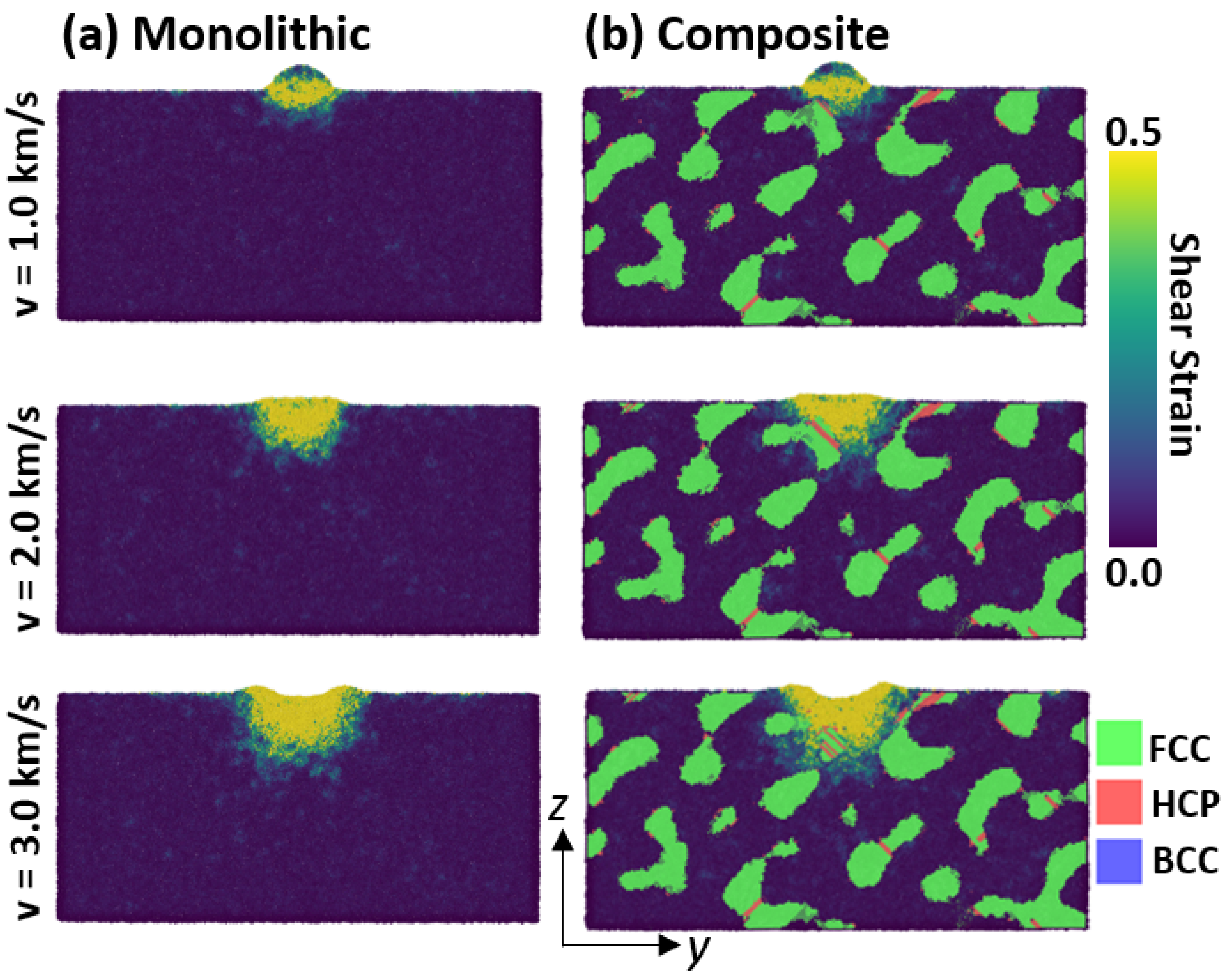
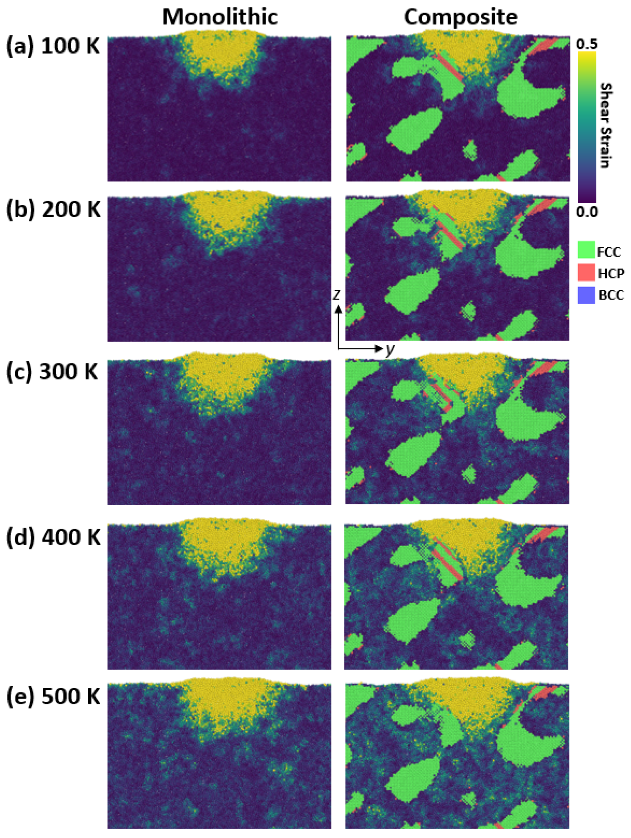
2.1. Deformation Fields

The deformation behavior of both the monolithic MG and the MG/Cu composite at an initial temperature of 100 K was analyzed using atomic shear strain for the amorphous phase and common neighbor analysis (CNA) for the crystalline phase, as shown in Figure 1. Higher impact velocities resulted in deeper penetration and increased projectile deformation, ultimately leading to disintegration at 3.0 km/s, consistent with previous studies on high-velocity impacts in metallic materials [26,42]. A comparison between the monolithic and composite samples reveals similar overall impact behavior. However, in the MG/Cu composite, plasticity is partially driven by deformation within the crystalline phase, resulting in the nucleation of stacking faults, a phenomenon typically observed in face-centered cubic (FCC) metals [43,44,45].

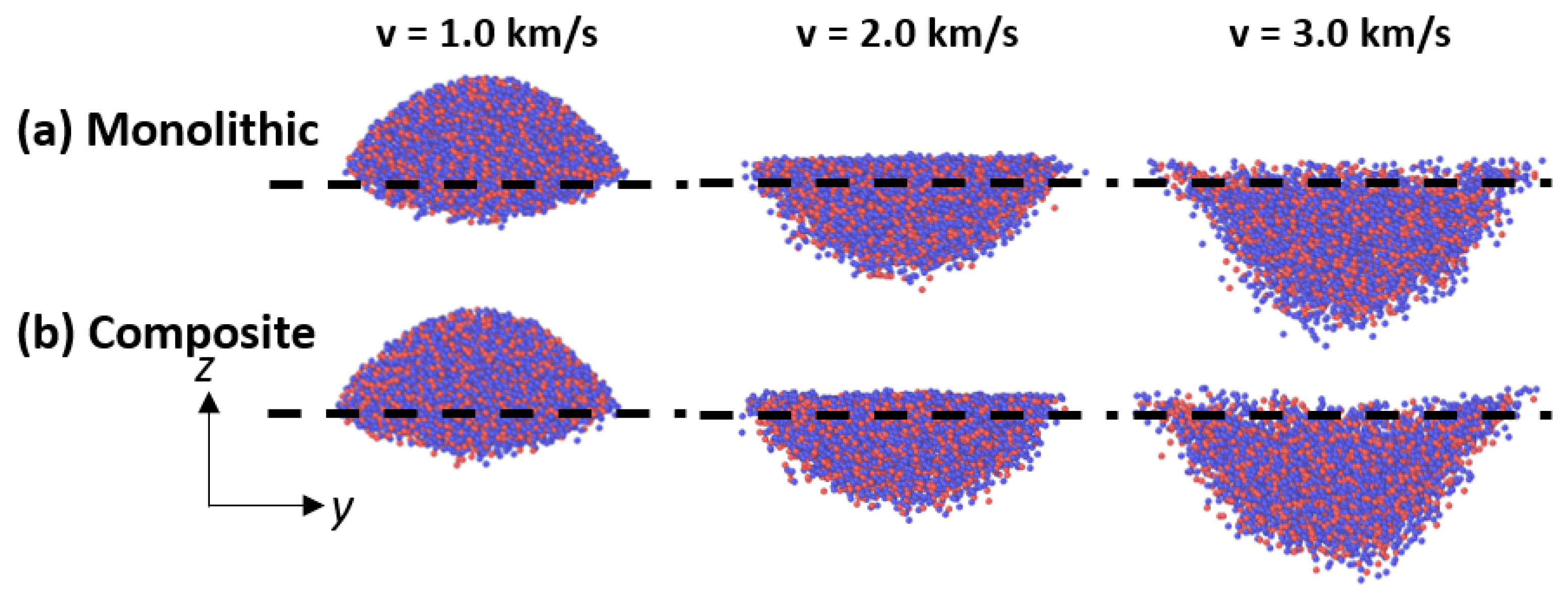
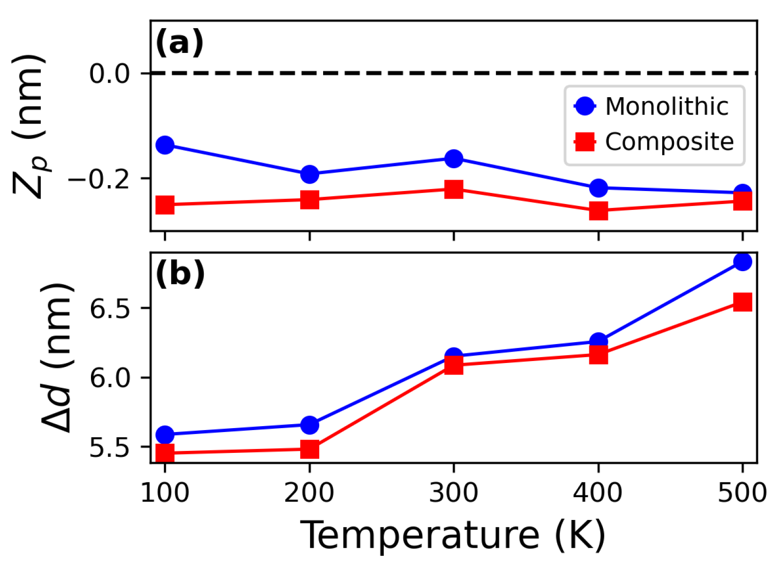
2.2. Penetration and Projectile Deformation

The vertical center-of-mass position of the projectile ( Z p ) after impact was determined by calculating its z-coordinate, using the upper surface of the substrate as a reference. As shown in Figure 2a, higher impact velocities result in deeper penetration, with both substrates exhibiting similar behavior. The degree of horizontal dispersion of the projectile ( Δ d ) was calculated as the difference between its post-impact radius and initial radius, with the results presented in Figure 2b. The projectile undergoes horizontal disintegration upon impact, consistent with previous studies on high-velocity impacts [21,26]. At lower velocities, Δ d is comparable for both substrates. However, as the impact velocity increases, Δ d becomes slightly higher for the monolithic MG substrate. This behavior can be attributed to the more homogeneous structure of the monolithic MG, which promotes a more uniform horizontal fragmentation of the projectile, as seen in the deformation fields in Figure 1.
Further insight into the deformation of the projectile is provided in Figure 3, where the dotted line represents the upper surface of the substrate. It is evident that at lower velocities, the projectile largely retains its original shape, while higher velocities lead to significant deformation and deeper embedding into the substrate. Moreover, the final shape of the projectile is similar for both the monolithic and composite substrates, consistent with the trends observed in Z p and Δ d .
High-velocity impacts result in substrates with elevated energy states. To investigate this effect, the variation in per-atom potential energy ( Δ U ) was quantified for both the monolithic and composite samples at different impact velocities. Δ U was calculated as the difference between the per-atom potential energy before and after impact. As shown in Figure 4a, Δ U increases with impact velocity due to the conversion of the projectile’s kinetic energy into potential energy within the substrate. This increase in internal energy resembles the rejuvenation process commonly observed in MGs [46,47,48], although further mechanical characterization is required to confirm this analogy. The monolithic sample exhibits a greater energy variation compared to the composite, which can be attributed to the higher stiffness of the single-crystal Cu phase. This suggests that the crystalline phase in the MG/Cu composite substrate is less capable of undergoing plastic deformation due to its increased stiffness relative to the glass matrix. For reference, the Young’s modulus of single-crystal Cu oriented along the 100 direction is approximately 100 GPa [49], whereas CuZr MGs typically range between 60–70 GPa, depending on atomic composition [36,50]. As a result, a greater amount of kinetic energy is required to produce a comparable increase in potential energy in the composite compared to the monolithic MG. Pile-up formation was also analyzed by measuring the maximum pile-up height relative to the substrate surface. As shown in Figure 4b, higher impact velocities lead to larger pile-ups. The monolithic sample exhibits lower pile-up heights than the composite, reflecting its reduced capacity for plastic deformation and atomic rearrangement in the bulk. This results in fewer atoms being displaced and accumulated at the surface. It is important to note that the pressure exerted by the projectile, along with the associated deformation, may modify the free volume and atomic structure of the amorphous phase through atomic rearrangements [51,52,53], which can enhance bulk deformation while reducing surface pile-up formation.

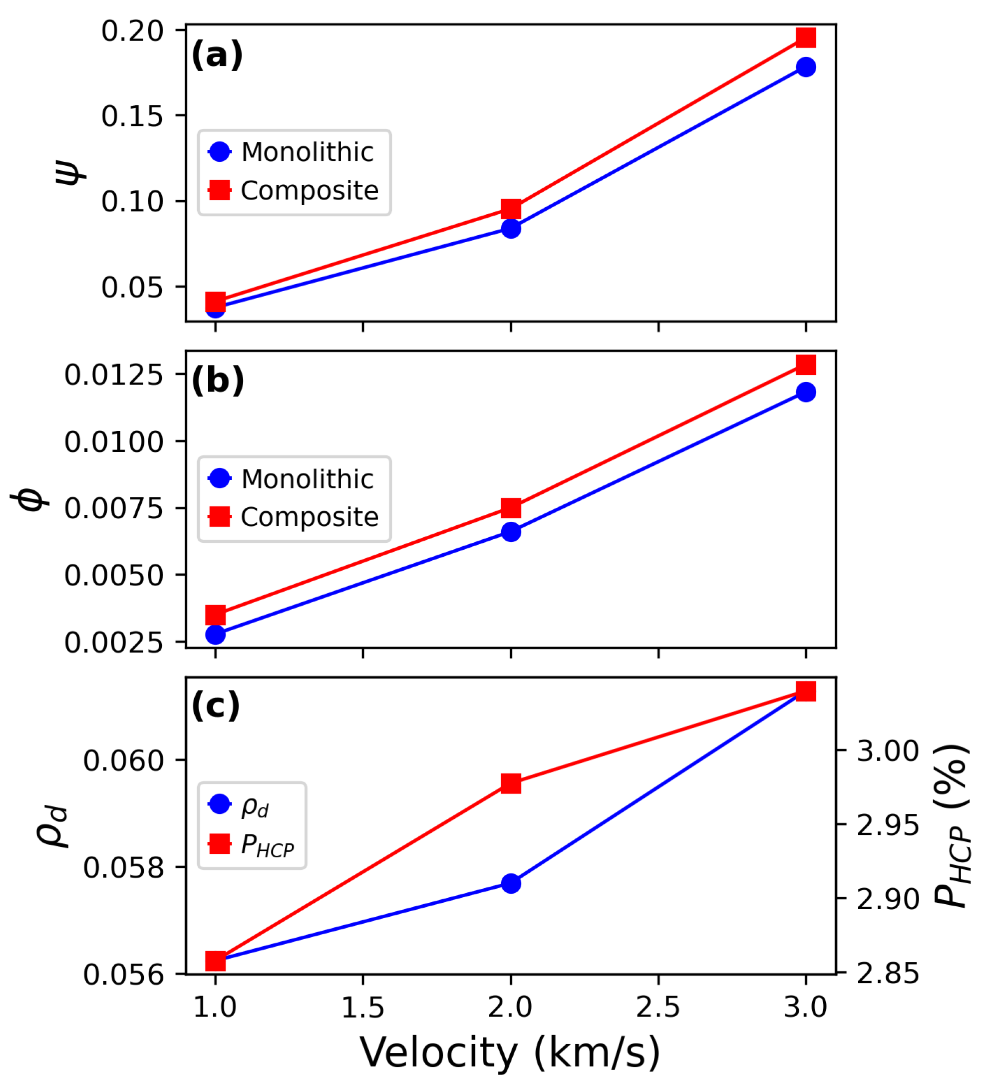
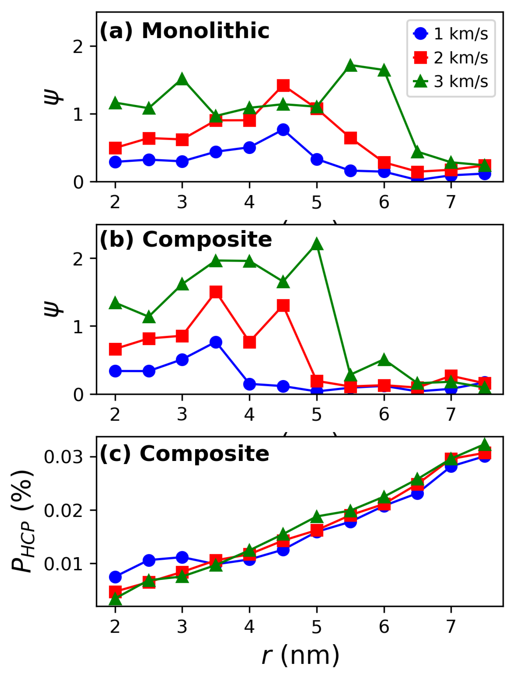
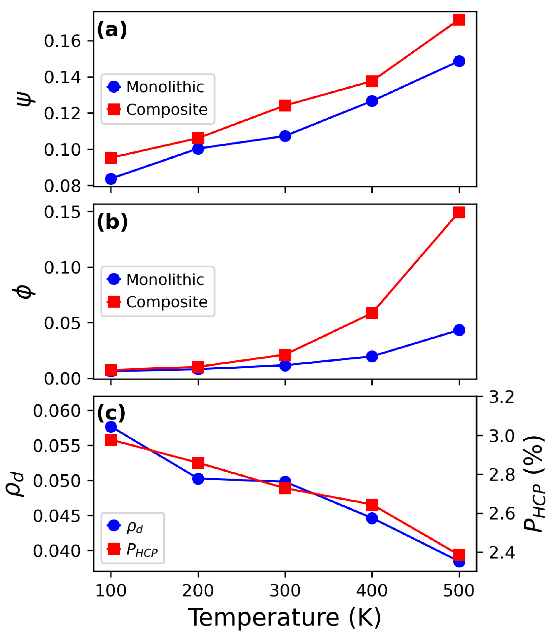
2.3. Quantification of Plastic Deformation

The high deformation fields induced significant plastic deformation in the samples. Plasticity in the amorphous phase was quantified using the degree of strain localization ( ψ ) and participation ratio ( ϕ ), while dislocation density ( ρ d ) and the population of HCP atoms ( P H C P ) were measured for the crystalline phase. These values are presented in Figure 5. As shown, all quantities exhibit an increasing trend with impact velocity, indicating greater energy transfer from the projectile to the substrate. A comparison between the substrates reveals that the composite undergoes higher strain localization and a greater number of participating atoms. This can be attributed to the increased stiffness of the crystalline phase in the composite, which induces more plastic activity in the amorphous matrix. Plastic characterization of the crystalline phase in the MG/Cu composite shows that both dislocation density and stacking fault formation increase with impact velocity, consistent with typical deformation mechanisms observed in FCC metals [43,44,45].
The distribution of plastic deformation was quantified in the radial direction from the impact region. To this end, the degree of strain localization and the population of HCP atoms were measured. The number of stacking faults was not explicitly quantified due to the difficulty of counting them directly. The resulting curves are shown in Figure 6. As observed, ψ increases with impact velocity and gradually decreases toward the bulk. When comparing the two substrates, ψ shows higher values in the composite, supporting our previous observation that the increased stiffness of the crystalline phase promotes deformation in the glass matrix. This is further confirmed by the radial distributions of HCP populations shown in Figure 6c. The populations are relatively small, consistent with the total populations observed in Figure 5c. The increasing trend of P H C P in the radial direction suggests a larger number of stacking faults, although an exact count of these defects is not possible. It is important to note that the bins for calculating P H C P become larger with increasing radial distance (r), which results in a higher fraction of HCP atoms being included in the calculation, thus explaining the observed trend.

2.4. Temperature Effect

To investigate the effect of initial temperature on the mechanical response of the substrate, five different initial temperatures were considered: 100 K, 200 K, 300 K, 400 K, and 500 K, with a fixed impact velocity of 2 km/s. The deformation fields for both substrates after impact are shown in Figure 7. A comparison across different initial temperatures reveals that higher kinetic energy leads to a greater number of atoms in the amorphous phase undergoing shear strain, consistent with previous studies [36,54]. However, the crystalline phase exhibits few differences. A comparison of both substrates at 500 K shows that the fraction of amorphous atoms experiencing high shear strain is larger in the composite substrate than in the monolithic one. This suggests that, despite the increased kinetic energy, the high stiffness of the crystalline phase inhibits its plastic deformation, leading to plastic events occurring predominantly in the glass matrix.
The Z p of the projectile was calculated for each case, with the results shown in Figure 8a. While Z p is higher for the composite case, as discussed in the previous section, a slight decrease with temperature is observed. However, this trend is not statistically significant due to the low percentage difference (3%). Regarding the degree of horizontal fragmentation of the projectile after impact, an increasing trend is observed for both cases, indicating that higher kinetic energy enhances projectile disintegration in the lateral directions. However, there is almost no difference between the two substrates.

2.5. Relationship Between Plastic Deformation and Temperature

Plastic deformation was quantified for different initial temperatures, as shown in Figure 9. Both the degree of strain localization ( ψ ) and participation ratio ( ϕ ) exhibit increasing trends with temperature, whereas dislocation density and the population of HCP atoms show the opposite behavior. Interestingly, the participation ratio remains similar for both substrates at low temperatures but becomes significantly higher for the composite at elevated temperatures. This behavior reflects two key phenomena. First, the crystalline phase has a limited ability to undergo plastic deformation due to its higher stiffness, as previously discussed. Second, the glass matrix experiences enhanced atomic rearrangement, attributed to its disordered structure. Regarding plastic activity in the crystalline phase, both ρ D and P H C P decrease with temperature, reinforcing the observation that most plastic deformation occurs in the glass matrix rather than in the crystalline structure when compared with the results of ϕ . Moreover, previous studies have shown that higher temperatures lead to lower dislocation densities, as increased kinetic energy promotes dislocation emission, mobility, and absorption [35,55,56].

2.6. Implications and Future Perspectives

The findings of this study offer valuable insights into the design of advanced protective materials for impact-prone environments, such as armor systems and aerospace structures exposed to space debris. The enhanced understanding of how MG and MG-based composites respond under extreme loading conditions can inform the development of lightweight, high-strength materials capable of dissipating large amounts of energy through localized plastic deformation. In particular, the superior plastic accommodation in MG matrices and the energy-dissipating capacity of composite architectures suggest promising avenues for tailoring impact-resistant coatings or layered shields. These results are especially relevant for spacecraft shielding, where minimizing mass while maximizing energy absorption is critical for mitigating damage from micrometeoroid and orbital debris impacts [57,58,59].
Despite the detailed atomic-level insights provided by MD simulations, the present study has some limitations. The simulations are restricted to nanometer-scale systems, which are difficult to explore experimentally. Moreover, the effects of interfacial properties and sample size were not fully explored and may influence deformation mechanisms in larger-scale systems. Future research could extend these findings by incorporating multi-scale modeling approaches and the evaluation of additional crystalline phase distributions. Additionally, understanding damage accumulation under repeated impacts or environmental effects such as oxidation or radiation would further enhance the applicability of MG-based composites in demanding operational environments.

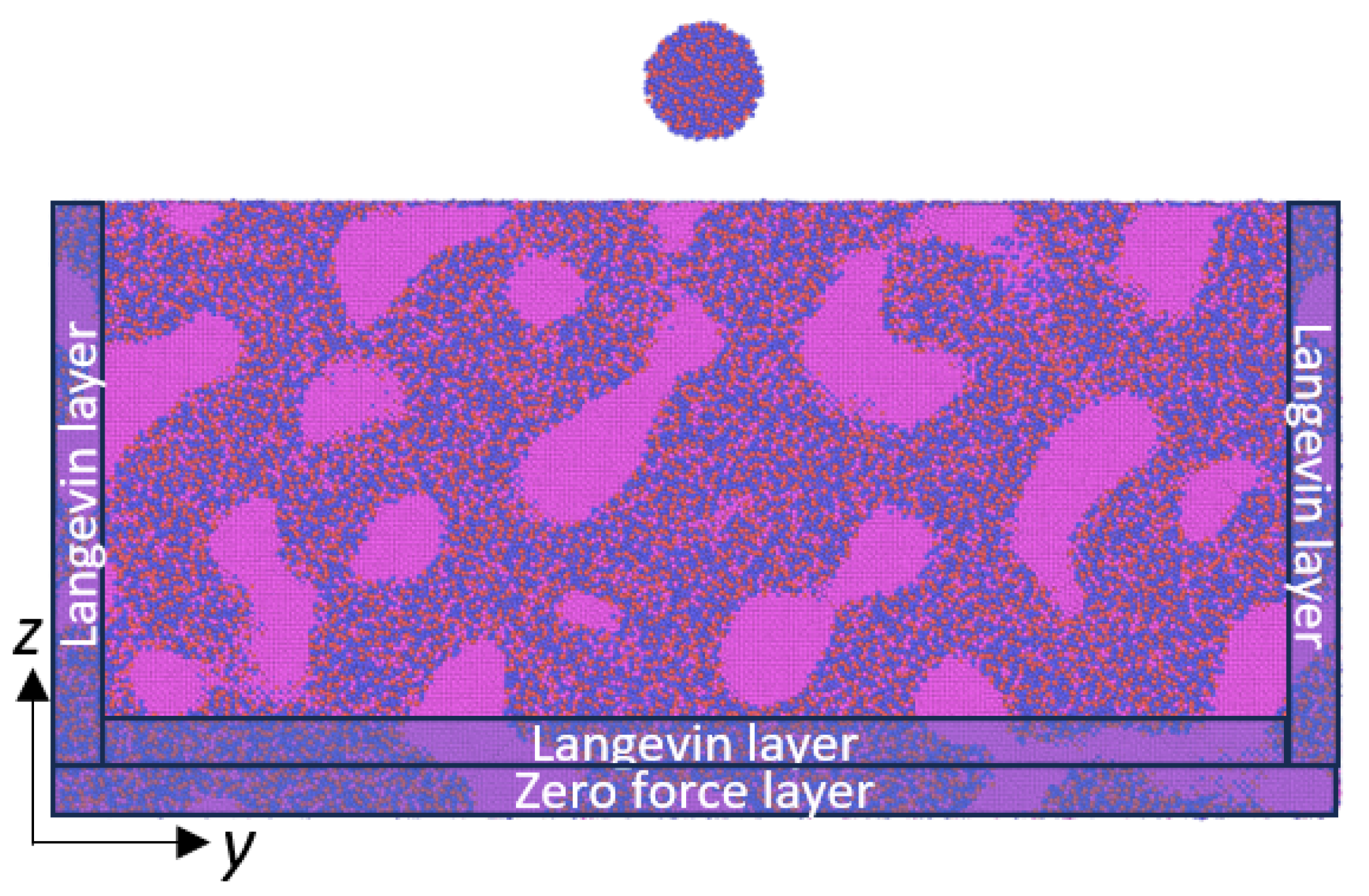
3. Materials and Methods

MD simulations were performed using the LAMMPS (version 29Aug2024) package [60,61]. Cu-Zr atomic interactions were modeled using the interatomic potential developed by Borovikov et al. [62]. This potential accurately describes the amorphous phase of CuZr MGs and provides reliable values for the stacking fault energy of single Cu structures. An integration timestep of 1.0 fs was employed for all simulations.
The CuZrMG was prepared by constructing a crystalline box with dimensions of 51.8 × 51.8 × 5.18 nm3 and an atomic composition of 64% Cu and 36% Zr. The sample was equilibrated at 2500 K for 2 ns under zero pressure using periodic boundary conditions (PBCs). Subsequently, a cooling rate of 10 11 K/s was applied to reduce the temperature to 100 K, followed by equilibration at zero pressure for 0.1 ns. The sample was replicated 10 times in the z-direction to obtain a larger structure. Finally, annealing at 600 K for 0.5 ns was performed to relieve stress at the artificial boundaries while maintaining zero pressure with PBCs.
A nanoporous MG structure was prepared using the algorithm proposed by Soyarslan et al. [63], based on the reaction-diffusion equation. Periodic waves f ( r ) were randomly generated according to the following expression:
f ( r ) = 2 N i = 1 N cos q i · r + α i
Here, q i , r , and α i are the wave vector, the position vector, and a random phase, respectively. The wave vector is calculated as
q i = 2 π ( h , k , l ) L ,
where L is the simulation length, and h, k, and l are the Miller indices. Spinodal-like structures with translational periodicity are obtained according to the condition H = h 2 + k 2 + l 2 , where | q i | = 2 π H / L is a constant. Porosity is introduced when f ( r ) > ζ , where ζ is a free parameter. The resulting sample had a porosity of 30%. The porous regions were filled with single-crystalline Cu, with the [ 100 ] , [ 010 ] , and [ 001 ] orientations aligned along the x-, y-, and z-directions, respectively. The MG/Cu composite was annealed at 600 K for 0.5 ns under zero pressure with PBCs. Subsequently, the sample was equilibrated at five target temperatures, T 0 : 100 K, 200 K, 300 K, 400 K, and 500 K. These MG/Cu composites were used as substrates for the impacts.
To simulate high-velocity impacts, a 5 nm-diameter MG nanoparticle was extracted from the bulk sample and positioned 5 nm above the substrate along the z-direction. Three different impact velocities were considered: 1 km/s, 2 km/s, and 3 km/s. A 1 nm-thick layer at the bottom of the substrate was set to zero force to prevent translational motion during the impact. Directly above this, a 1 nm-thick layer in the z-direction, as well as a 1 nm-thick layer along the outer edges of the x- and y-directions, was assigned a Langevin thermostat at a constant temperature T 0 to absorb the elastic waves generated during the impact. The inner region of the substrate was simulated under the NVE ensemble. A schematic of the projectile/substrate configuration is shown in Figure 10. Impacts were also performed on a monolithic MG for comparison purposes.
Plasticity was quantified with the atomic shear strain [64]. The degree of strain localization was obtained as [65]
ψ = 1 N i = 1 N ( η i η a v e ) 2 ,
where N is the number of atoms, η i is the von Mises strain of atom i obtained from the atomic shear strain, and η a v e is the average von Mises strain. The deformation participation ratio ( ϕ ) was obtained as [66,67]
ϕ = N η > 0.2 N t ,
where N η > 0.2 is the number of atoms with von Mises strain greater than 0.2 and N t is the total number of atoms. The dislocation density ( ρ d ) was calculated using ρ d = L / V , where L is the total dislocation length provided by the DXA algorithm (the sum of all the dislocation lengths) [68], and V is the total substrate volume. Crystalline structure was identified with the common neighbor analysis algorithm (CNA) [69], which was used to quantify the populations of HCP atoms. Visualization was performed using the OVITO (version 3.12.1) software [70].

4. Conclusions

The present study investigated the mechanical response of monolithic CuZr metallic glass (MG) and MG/Cu composite substrates under high-velocity impact using molecular dynamics simulations, considering variations in impact velocity and initial temperature.
Increasing the impact velocity led to deeper penetration and greater plastic deformation of both substrates. At higher velocities, the projectile exhibited more pronounced horizontal fragmentation in the monolithic substrate due to its homogeneous structure. The MG/Cu composite exhibited increased plasticity, attributed to the higher stiffness of the crystalline phase, which induced plastic deformation in the glass matrix. This difference in stiffness also influenced energy absorption, as the monolithic MG showed greater variations in potential energy due to its higher capacity for atomic rearrangement.
Temperature effects were primarily observed in the amorphous phase, where increasing the initial temperature enhanced shear strain localization and atomic mobility. In contrast, the crystalline phase exhibited lower variations in deformation behavior due to enhanced dislocation emission and absorption with temperature. This decrease in dislocation density and HCP atom population indicated that plastic activity shifted predominantly to the amorphous phase at elevated temperatures.
In summary, the MG/Cu composite displayed increased plasticity and lower energy variation, with the crystalline phase exhibiting little deformation. This indicates that the energy transferred from the projectile to the monolithic sample results in higher energy states rather than plastic deformation. Furthermore, higher temperatures induced more localized plasticity within the amorphous matrix, emphasizing the role of atomic mobility and structural disorder in accommodating deformation. These findings highlight the interplay between impact velocity, temperature, and material composition in governing plastic deformation mechanisms, providing insight into the response of MG-based composites under extreme loading conditions.

Supplementary Materials

The following supporting information can be downloaded at https://www.mdpi.com/article/10.3390/inorganics13050141/s1.

Author Contributions

N.A.: conceptualization, software, investigation, methodology, visualization, formal analysis, writing—review and editing—original draft, resources. J.W.: formal analysis, visualization. P.L.-P.: investigation, visualization. All authors have read and agreed to the published version of the manuscript.

Funding

Project supported by the Competition for Research Regular Projects, year 2023, code LPR23-05, Universidad Tecnológica Metropolitana. Powered@NLHPC: This research was partially supported by the supercomputing infrastructure of the NLHPC (ECM-02).

Data Availability Statement

The original contributions presented in this study are included in the Supplementary Material. Further inquiries can be directed to the corresponding author.

Conflicts of Interest

The authors declare no conflicts of interest.

References

  1. Ryan, S.; Schaefer, F.; Destefanis, R.; Lambert, M. A ballistic limit equation for hypervelocity impacts on composite honeycomb sandwich panel satellite structures. Adv. Space Res. 2008, 41, 1152–1166. [Google Scholar] [CrossRef]
  2. Pieters, C.M.; Noble, S.K. Space weathering on airless bodies. J. Geophys. Res. Planets 2016, 121, 1865–1884. [Google Scholar] [CrossRef]
  3. Kılıc, N.; Bedir, S.; Erdik, A.; Ekici, B.; Tasdemirci, A.; Guden, M. Ballistic behavior of high hardness perforated armor plates against 7.62 mm armor piercing projectile. Mater. Des. 2014, 63, 427–438. [Google Scholar] [CrossRef]
  4. Cour-Palais, B.G. Hypervelocity impact in metals, glass and composites. Int. J. Impact Eng. 1987, 5, 221–237. [Google Scholar] [CrossRef]
  5. Safri, S.; Sultan, M.; Yidris, N.; Mustapha, F. Low velocity and high velocity impact test on composite materials–a review. Int. J. Eng. Sci 2014, 3, 50–60. [Google Scholar]
  6. Collins, G.S.; Melosh, H.J.; Ivanov, B.A. Modeling damage and deformation in impact simulations. Meteorit. Planet. Sci. 2004, 39, 217–231. [Google Scholar] [CrossRef]
  7. Seaman, L.; Curran, D.R.; Shockey, D.A. Computational models for ductile and brittle fracture. J. Appl. Phys. 1976, 47, 4814–4826. [Google Scholar] [CrossRef]
  8. Wensink, H.; Elwenspoek, M.C. A closer look at the ductile-brittle transition in solid particle erosion. Wear 2002, 253, 1035–1043. [Google Scholar] [CrossRef]
  9. Michel, Y.; Chevalier, J.M.; Durin, C.; Espinosa, C.; Malaise, F.; Barrau, J.J. Hypervelocity impacts on thin brittle targets: Experimental data and SPH simulations. Int. J. Impact Eng. 2006, 33, 441–451. [Google Scholar] [CrossRef]
  10. Hao, G.; Dong, X.; Du, M.; Li, Z.; Dou, Z. A comparative study of ductile and brittle materials due to single angular particle impact. Wear 2019, 428–429, 258–271. [Google Scholar] [CrossRef]
  11. Pham, T.M.; Hao, H. Influence of global stiffness and equivalent model on prediction of impact response of RC beams. Int. J. Impact Eng. 2018, 113, 88–97. [Google Scholar] [CrossRef]
  12. Hassani, M.; Veysset, D.; Nelson, K.A.; Schuh, C.A. Material hardness at strain rates beyond 106 s-1 via high velocity microparticle impact indentation. Scr. Mater. 2020, 177, 198–202. [Google Scholar] [CrossRef]
  13. Cai, J.; Griesbach, C.; Ahnen, S.G.; Thevamaran, R. Dynamic Hardness Evolution in Metals from Impact Induced Gradient Dislocation Density. Acta Mater. 2023, 249, 118807. [Google Scholar] [CrossRef]
  14. Fortov, V.; Kim, V.; Lomonosov, I.; Matveichev, A.; Ostrik, A. Numerical modeling of hypervelocity impacts. Int. J. Impact Eng. 2006, 33, 244–253. [Google Scholar] [CrossRef]
  15. Tan, V.; Ching, T. Computational simulation of fabric armour subjected to ballistic impacts. Int. J. Impact Eng. 2006, 32, 1737–1751. [Google Scholar] [CrossRef]
  16. Kilic, N.; Ekici, B.; Hartomacıoglu, S. Determination of penetration depth at high velocity impact using finite element method and artificial neural network tools. Def. Technol. 2015, 11, 110–122. [Google Scholar] [CrossRef]
  17. Žmindák, M.; Pelagić, Z.; Pastorek, P.; Močilan, M.; Vybošťok, M. Finite Element Modelling of High Velocity Impact on Plate Structures. Procedia Eng. 2016, 136, 162–168. [Google Scholar] [CrossRef]
  18. Yehia Abdel-Nasser, A.M.E.; Al-Mallah, I. Impact analysis of composite laminate using finite element method. Ships Offshore Struct. 2017, 12, 219–226. [Google Scholar] [CrossRef]
  19. Madhukar, A.; Ostoja-Starzewski, M. Finite Element Methods in Human Head Impact Simulations: A Review. Ann. Biomed. Eng. 2019, 47, 1832–1854. [Google Scholar] [CrossRef]
  20. Song, G.; Yang, H.; Hogan, C.J. Thermal energy evolution and mechanical deformation of monocrystalline yttria-stabilized zirconia nanoparticles in aerosol deposition processes. Appl. Surf. Sci. 2022, 585, 152603. [Google Scholar] [CrossRef]
  21. Burlison, S.; Becker, M.F.; Kovar, D. A molecular dynamics study of the effects of velocity and diameter on the impact behavior of zinc oxide nanoparticles. Model. Simul. Mater. Sci. Eng. 2023, 31, 075008. [Google Scholar] [CrossRef]
  22. Song, G.; Hogan, C.J. Crystal grain size effects and crystallinity dynamics during supersonic particle impacts. Int. J. Plast. 2023, 170, 103758. [Google Scholar] [CrossRef]
  23. Amigo, N. Deposition of droplets on metallic glass substrates: Thermophysical and structural characterization. J. Mol. Liq. 2025, 421, 126879. [Google Scholar] [CrossRef]
  24. Chitrakar, T.V.; Becker, M.F.; Kovar, D. Influence of Crystallographic Orientation on the Deformation of Ag Nanoparticles During High-Speed Impact. J. Therm. Spray Technol. 2023, 32, 2683–2700. [Google Scholar] [CrossRef]
  25. Dutta, A. Surface damage of CuZr metallic glass by hypervelocity nano-projectile: A molecular dynamics study. Comput. Mater. Sci. 2018, 141, 41–48. [Google Scholar] [CrossRef]
  26. Wachter, J.; Amigo, N.; Gutiérrez, G.; Zúñiga, A. Atomic scale study of the impact of metallic glass nanoparticles at high velocities. J. Non-Cryst. Solids 2024, 628, 122866. [Google Scholar] [CrossRef]
  27. Dwivedi, P.; Fraile, A.; Polcar, T. Tungsten wall cratering under high-velocity dust impacts: Influence of impact angle and temperature. J. Nucl. Mater. 2024, 600, 155289. [Google Scholar] [CrossRef]
  28. Greer, A.L. Metallic glasses…on the threshold. Mater. Today 2009, 12, 14–22. [Google Scholar] [CrossRef]
  29. Schroers, J. Processing of Bulk Metallic Glass. Adv. Mater. 2010, 22, 1566–1597. [Google Scholar] [CrossRef]
  30. Chen, M. A brief overview of bulk metallic glasses. NPG Asia Mater. 2011, 3, 82–90. [Google Scholar] [CrossRef]
  31. Wu, F.F.; Chan, K.C.; Jiang, S.S.; Chen, S.H.; Wang, G. Bulk metallic glass composite with good tensile ductility, high strength and large elastic strain limit. Sci. Rep. 2014, 4, 5302. [Google Scholar] [CrossRef]
  32. Qiao, J.; Jia, H.; Liaw, P.K. Metallic glass matrix composites. Mater. Sci. Eng. Rep. 2016, 100, 1–69. [Google Scholar] [CrossRef]
  33. Sha, Z.D.; Branicio, P.S.; Lee, H.P.; Tay, T.E. Strong and ductile nanolaminate composites combining metallic glasses and nanoglasses. Int. J. Plast. 2017, 90, 231–241. [Google Scholar] [CrossRef]
  34. Fu, X.; Wang, G.; Wu, Y.; Song, W.; Shek, C.H.; Zhang, Y.; Shen, J.; Ritchie, R.O. Compressive ductility and fracture resistance in CuZr-based shape-memory metallic-glass composites. Int. J. Plast. 2020, 128, 102687. [Google Scholar] [CrossRef]
  35. Yaghoobi, M.; Voyiadjis, G.Z. The effects of temperature and strain rate in fcc and bcc metals during extreme deformation rates. Acta Mater. 2018, 151, 1–10. [Google Scholar] [CrossRef]
  36. Amigo, N.; Careglio, C.A.; Ardiani, F.; Manelli, A.; Tramontina, D.R.; Bringa, E.M. Thermal effects on the mechanical behavior of CuZr metallic glasses. Appl. Phys. A 2024, 130, 616. [Google Scholar] [CrossRef]
  37. Amigo, N. Mechanical characterization of nanocrystalline Cu-Ag alloys subjected to shear deformation. Mol. Simul. 2024, 50, 1411–1419. [Google Scholar] [CrossRef]
  38. Reddy, K.V.; Deng, C.; Pal, S. Dynamic characterization of shock response in crystalline-metallic glass nanolaminates. Acta Mater. 2019, 164, 347–361. [Google Scholar] [CrossRef]
  39. Zhang, J.; Wang, X.; Zhang, M.; Deng, L.; Gong, P. The shock forming process of Cu50Zr50 metallic glasses studied via molecular dynamics simulation. J. Non-Cryst. Solids 2022, 584, 121518. [Google Scholar] [CrossRef]
  40. Song, W.; Yu, Y.; Guan, Y. Role of void shape on shock responses of nanoporous metallic glasses via molecular dynamics simulation. Int. J. Mech. Sci. 2022, 218, 107076. [Google Scholar] [CrossRef]
  41. Song, W.; Meng, Y.; Xiao, L.; Liu, S. Tuning dynamic mechanical properties of Cu50Zr50 nanoglasses/ nanopolycrystalline Cu composites investigated by molecular dynamics simulation. J. Non-Cryst. Solids 2024, 625, 122715. [Google Scholar] [CrossRef]
  42. Jami, H.; Jabbarzadeh, A. Molecular simulation of high-velocity deposition of titanium dioxide nanoparticles on titanium. Appl. Surf. Sci. 2021, 542, 148567. [Google Scholar] [CrossRef]
  43. Stukowski, A.; Albe, K.; Farkas, D. Nanotwinned fcc metals: Strengthening versus softening mechanisms. Phys. Rev. B 2010, 82, 224103. [Google Scholar] [CrossRef]
  44. Asadi, E.; Zaeem, M.A.; Moitra, A.; Tschopp, M.A. Effect of vacancy defects on generalized stacking fault energy of fcc metals. J. Physics: Condens. Matter 2014, 26, 115404. [Google Scholar] [CrossRef] [PubMed]
  45. Amigo, N. Mechanical Properties of Copper with Dendritic Silver Inclusions: Insights from Molecular Dynamics Simulations. Comput. Mater. Contin. 2024, 81, 3665–3678. [Google Scholar] [CrossRef]
  46. Priezjev, N.V. Aging and rejuvenation during elastostatic loading of amorphous alloys: A molecular dynamics simulation study. Comput. Mater. Sci. 2019, 168, 125–130. [Google Scholar] [CrossRef]
  47. Wang, M.; Liu, H.; Li, J.; Jiang, Q.; Yang, W.; Tang, C. Thermal-pressure treatment for tuning the atomic structure of metallic glass Cu-Zr. J. Non-Cryst. Solids 2020, 535, 119963. [Google Scholar] [CrossRef]
  48. Amigo, N. Cryogenic thermal cycling rejuvenation in metallic glasses: Structural and mechanical assessment. J. Non-Cryst. Solids 2022, 596, 121850. [Google Scholar] [CrossRef]
  49. Gao, Y.; Wang, H.; Zhao, J.; Sun, C.; Wang, F. Anisotropic and temperature effects on mechanical properties of copper nanowires under tensile loading. Comput. Mater. Sci. 2011, 50, 3032–3037. [Google Scholar] [CrossRef]
  50. Amigo, N.; Valencia, F. Mechanical and structural assessment of CuZr metallic glasses rejuvenated by thermal-pressure treatments. Comput. Mater. Sci. 2021, 198, 110681. [Google Scholar] [CrossRef]
  51. Heggen, M.; Spaepen, F.; Feuerbacher, M. Creation and annihilation of free volume during homogeneous flow of a metallic glass. J. Appl. Phys. 2004, 97, 033506. [Google Scholar] [CrossRef]
  52. Yoo, B.G.; Kim, J.Y.; Kim, Y.J.; Choi, I.C.; Shim, S.; Tsui, T.Y.; Bei, H.; Ramamurty, U.; Jang, J.I. Increased time-dependent room temperature plasticity in metallic glass nanopillars and its size-dependency. Int. J. Plast. 2012, 37, 108–118. [Google Scholar] [CrossRef]
  53. Qiu, Y.; Xu, C.; Fu, E.; Wang, P.; Du, J.; Hu, Z.; Yan, X.; Cao, X.; Wang, Y.; Shao, L. Mechanisms for the free volume tuning the mechanical properties of metallic glass through ion irradiation. Intermetallics 2018, 101, 173–178. [Google Scholar] [CrossRef]
  54. Jafary-Zadeh, M.; Tavakoli, R.; Srolovitz, D.J.; Zhang, Y.W. Thermally induced failure mechanism transition and its correlation with short-range order evolution in metallic glasses. Extrem. Mech. Lett. 2016, 9, 215–225. [Google Scholar] [CrossRef]
  55. Rohith, P.; Sainath, G.; Srinivasan, V. Effect of size, temperature and strain rate on dislocation density and deformation mechanisms in Cu nanowires. Phys. Condens. Matter 2019, 561, 136–140. [Google Scholar] [CrossRef]
  56. Saffarini, M.H.; Voyiadjis, G.Z.; Ruestes, C.J. Temperature effect on nanoporous gold under uniaxial tension and compression. Comput. Mater. Sci. 2021, 200, 110766. [Google Scholar] [CrossRef]
  57. Grossman, E.; Gouzman, I.; Verker, R. Debris/Micrometeoroid Impacts and Synergistic Effects on Spacecraft Materials. MRS Bull. 2010, 35, 41–47. [Google Scholar] [CrossRef]
  58. Schonberg, W.P. Protecting Earth-orbiting spacecraft against micro-meteoroid/orbital debris impact damage using composite structural systems and materials: An overview. Adv. Space Res. 2010, 45, 709–720. [Google Scholar] [CrossRef]
  59. Rakib, M.A.; Smith, S.T.; Tafsirojjaman, T. A review of shielding systems for protecting off-earth structures from micrometeoroid and orbital debris impact. Acta Astronaut. 2024, 223, 404–425. [Google Scholar] [CrossRef]
  60. Plimpton, S. Fast Parallel Algorithms for Short-Range Molecular Dynamics. J. Comput. Phys. 1995, 117, 1–19. [Google Scholar] [CrossRef]
  61. Thompson, A.P.; Aktulga, H.M.; Berger, R.; Bolintineanu, D.S.; Brown, W.M.; Crozier, P.S.; In’t Veld, P.J.; Kohlmeyer, A.; Moore, S.G.; Nguyen, T.D.; et al. LAMMPS–A flexible simulation tool for particle-based materials modeling at the atomic, meso, and continuum scales. Comp. Phys. Comm. 2022, 271, 108171. [Google Scholar] [CrossRef]
  62. Borovikov, V.; Mendelev, M.I.; King, A.H. Effects of stable and unstable stacking fault energy on dislocation nucleation in nano-crystalline metals. Model. Simul. Mater. Sci. Eng. 2016, 24, 085017. [Google Scholar] [CrossRef]
  63. Soyarslan, C.; Bargmann, S.; Pradas, M.; Weissmüller, J. 3D stochastic bicontinuous microstructures: Generation, topology and elasticity. Acta Mater. 2018, 149, 326–340. [Google Scholar] [CrossRef]
  64. Shimizu, F.; Ogata, S.; Li, J. Theory of Shear Banding in Metallic Glasses and Molecular Dynamics Calculations. Mater. Trans. 2007, 48, 2923–2927. [Google Scholar] [CrossRef]
  65. Cheng, Y.Q.; Cao, A.J.; Ma, E. Correlation between the elastic modulus and the intrinsic plastic behavior of metallic glasses: The roles of atomic configuration and alloy composition. Acta Mater. 2009, 57, 3253–3267. [Google Scholar] [CrossRef]
  66. Shi, Y.; Falk, M.L. Strain Localization and Percolation of Stable Structure in Amorphous Solids. Phys. Rev. Lett. 2005, 95, 095502. [Google Scholar] [CrossRef]
  67. Adibi, S.; Branicio, P.S.; Joshi, S.P. Suppression of Shear Banding and Transition to Necking and Homogeneous Flow in Nanoglass Nanopillars. Sci. Rep. 2015, 5, 15611. [Google Scholar] [CrossRef]
  68. Stukowski, A. Structure identification methods for atomistic simulations of crystalline materials. Model. Simul. Mater. Sci. Eng. 2012, 20, 045021. [Google Scholar] [CrossRef]
  69. Faken, D.; Jónsson, H. Systematic analysis of local atomic structure combined with 3D computer graphics. Comput. Mater. Sci. 1994, 2, 279–286. [Google Scholar] [CrossRef]
  70. Stukowski, A. Visualization and analysis of atomistic simulation data with OVITO–the Open Visualization Tool. Model. Simul. Mater. Sci. Eng. 2010, 18, 015012. [Google Scholar] [CrossRef]
Figure 1. Cross-section view of the deformation fields for the monolithic and MG/Cu composites at different velocities. The amorphous and crystalline phases are colored according to atomic shear strain and CNA, respectively. The substrates were at an initial temperature of 100 K.
Inorganics 13 00141 g001
Figure 2. (a) Penetration depth ( Z p ) into the substrate and (b) horizontal deformation of the projectile. The dotted line in Z p represents the position of the substrate surface.
Inorganics 13 00141 g002
Figure 3. Projectile after 0.6 ns relaxation time for the (a) monolithic and (b) composite substrate. The dotted line represents the substrate upper surface. Red and blue colors represent Cu and Zr atoms, respectively.
Inorganics 13 00141 g003
Figure 4. (a) Increase of the substrate per-atom potential energy and (b) crater pile-up after impact.
Inorganics 13 00141 g004
Figure 5. (a) Degree of strain localization ( ψ ) and (b) participation ratio ( ϕ ) for the entire substrate. (c) Dislocation density ( ρ d ) and population of HCP atoms ( P H C P ) for the crystalline phase.
Inorganics 13 00141 g005
Figure 6. Radial distribution of the degree of strain localization ( ψ ) for the (a) monolithic and (b) composite substrate. (c) Radial distribution of the population of HCP atoms in the composite substrate.
Inorganics 13 00141 g006
Figure 7. Cross-section view of the deformation fields for the monolithic and MG/Cu composites at different initial temperatures. The amorphous and crystalline phases are colored according to atomic shear strain and CNA, respectively.
Inorganics 13 00141 g007
Figure 8. (a) Penetration depth ( Z p ) into the substrate. (b) Horizontal deformation of the projectile when considering different substrate temperatures and an impact velocity of 2 km/s.
Inorganics 13 00141 g008
Figure 9. (a) Degree of strain localization ( ψ ) and (b) participation ratio ( ϕ ) for the entire substrate, and (c) dislocation density ( ρ d ) and population of HCP atoms ( P H C P ) for the crystalline phase for the substrate prepared at different initial temperatures. The considered impact velocity is 2 km/s.
Inorganics 13 00141 g009
Figure 10. Scheme of the 1 nm-thick zero force and Langevin layers used in the simulations. The layers are not to scale for visualization purposes. Red and blue colors represent Cu and Zr atoms, respectively. Pink represents the crystalline phase.
Inorganics 13 00141 g010
Disclaimer/Publisher’s Note: The statements, opinions and data contained in all publications are solely those of the individual author(s) and contributor(s) and not of MDPI and/or the editor(s). MDPI and/or the editor(s) disclaim responsibility for any injury to people or property resulting from any ideas, methods, instructions or products referred to in the content.

