Article

The Effect of Localized Magnetic Fields on the Spatially Controlled Crystallization of Transition Metal Complexes

1
School of Natural Sciences, Bangor University, Deiniol Road, Bangor LL57 2DG, UK
2
National Crystallography Service, School of Chemistry and Chemical Engineering, University of Southampton, Southampton SO17 1BJ, UK
3
School of Pharmacy and Life Sciences, Faculty of Science and Engineering, University of Wolverhampton, Wulfruna Street, Wolverhampton WV1 1LY, UK
*
Authors to whom correspondence should be addressed.
Inorganics 2025, 13(4), 117; https://doi.org/10.3390/inorganics13040117
Submission received: 27 February 2025 / Revised: 27 March 2025 / Accepted: 31 March 2025 / Published: 7 April 2025
(This article belongs to the Section Inorganic Solid-State Chemistry)

Abstract

:
A series of nickel (II) bis-phosphine organometallic complexes along with two pseudo [M7] (M = Ni(II), Zn(II)) metallocalix[6]arene complexes and a dysprosium acetate coordination polymer have each been crystallised in the presence of localized magnetic fields set up using neodymium magnets, using custom made Magnetic Crystallization Towers (MCTs). In all cases, whether the product complex is diamagnetic or paramagnetic, a complex spatial patterning of the crystals occurs based on the orientation of the magnetic field lines. When using magnetic block towers, the crystallization generally occurs adjacent to the magnet face. The effects of nucleation and solution concentration gradients on the crystallization process are also explored. These observations show how the crystallization process is affected by magnetic fields and thus these results have far-reaching effects which most certainly will include crystallization and ion migrations in biology.

Graphical Abstract

1. Introduction

One area of chemistry which has to some extent been neglected is chemistry in magnetic fields [1,2,3,4,5,6,7,8]. There are many biological phenomena associated with weak magnetic fields such as bird navigation and effects on the human body, yet the mechanism of these actions is still poorly understood. In chemistry, the use of EPR spectroscopy plays an important role in the study of materials in spectroscopic terms, however the bulk effects in solution in synthetic chemistry are less well studied. The work of Tesla and Faraday inspired generations of electromagnetic researchers, which has essentially taken us to where we are today in terms of electronic components. Despite the significant number of articles on single-molecule magnets [9,10,11], the linking of magnetochemistry to bulk synthesis is sorely lacking. One rather obvious application is crystallization in magnetic fields. Several years ago (2015–2017), we carried out the first of these experiments, which we can now report. We have undertaken a raft of experiments with both paramagnetic and diamagnetic compounds and have observed astonishing results. It is intuitively obvious that the crystallization of paramagnetic complexes in magnetic fields may provide interesting research results, but it is perhaps less obvious that diamagnetic compounds which are weakly repelled from magnetic fields should also show this effect; that is, until we realize that in all compounds electron motion will cause many localized fields which are susceptible to magnetic fields. The original inspiration for this work came from teaching demonstrations of the Meisner effect [12,13,14] where a static conventional ceramic superconductor clearly shows the effect of concerted magnetic repulsion but in a localized manner unlike that of conventional magnets where stabilization of the third degree of freedom is required. The other aspect which should also be obvious is that the different effects on the HOMO and LUMO molecular orbitals in a magnetic field should influence the course of a chemical reaction or at least be responsible for the catalysis of chemical reactions if a well-designed reactor can be built—clearly the very local effects of magnetic fields mean that the substrate-–magnet distances should be short or chemistry in high magnetic fields could be carried out inside electromagnets. The other phenomenon which is clearly at play is the effect of local currents within the solutions because material transport in solutions leading to concentration gradients is clearly important. In the present context, it is best to begin with pictorial representations of crystallisations in a magnetic field.
Magnetic fields, generated either by electromagnets or permanent commercially available magnets, have long been used to treat hard water [15,16,17]. The application of a magnetic field has been shown to strongly influence fluid-flow hydrodynamics that in-turn directly affect aggregation and/or disaggregation of colloidal solids (e.g., calcite and aragonite from hard water) [18]. It is also believed that magnetic field effects significantly influence crystallisation processes in solution (of both diamagnetic and paramagnetic substances). For instance, the crystallisation of protein structures using external magnetic fields has become commonplace in protein crystallography and can be carried out in both solutions and gel media [19,20,21,22]. Indeed, a very recent and significant development demonstrated that hen egg white lysozyme (HEWL) could be crystallised in a contactless fashion through levitation (HEWL is suspended in a solution) using external magnets in the form of a “magnetic force booster” [23]. Similarly, Whitesides and co-workers have employed magneto-Archimedes levitation (MagLev) to separate mixtures of crystal polymorphs using density differentiation. This was achieved using a sophisticated self-built device comprising two permanent magnets (like-poles facing each other) separated by a void space that accommodates a sample cuvette containing the crystal mixture [24]. In 2019, the same device was successfully employed in the density-driven separation and identification of illicit drugs at much lower quantities/concentrations (<50 mg) than are required using standard forensic methodologies. This was achieved using the MagLev phenomenon in combination with FT-IR and/or 1H NMR [25].
In a similar vein, Chen and co-workers have shown that the application of a strong magnetic field (90 kOe) during the preparation of the multiferroic formate perovskite [(CH3)2NH2][Mn(HCOO)3] leads to slight topological changes within the resultant extended architecture and significant changes in magnetic behaviour [26]. Similarly, Hong and co-workers were able to introduce molecular disorder and important topological changes that encouraged altered magnetic behaviour within a [Fe(1,4-dcb)(N(CN)2)2] complex (1,4-dbc = 1,4-dichlorobenzene). Interestingly, at higher magnetic fields (1 T) a complete breakdown of the complex was observed as indicated by the crystallisation of Fe(ClO4)2.6H2O precursor [27]. In 2014, Meihaus and co-workers discovered that the nearby positioning of a permanent Nd2Fe13B magnet promoted the crystallisation of the otherwise stubborn N23− radical bridged lanthanide complexes [{(R2N)2(THF)Ln}23222-N2)K] (Ln = Gd, Tb, Dy; NR2 = N(SiMe3)2) as opposed to the otherwise favoured non-radical azide-bridged analogue complexes [28]. Similarly, using a Fe14Nd2B magnet, Higgins et al. carried out extremely effective thermal gradient-driven separation of both dia- and paramagnetic rare-earth [RE(TriNOx)] complexes from complex mixtures [29]. In 2019, Naaman and co-workers employed a 0.52 T permanent magnet to execute the enantiospecific crystallisation of amino acids (asparagine, glutamic acid hydrochloride and threonine) [30]. In the same year, a potentially groundbreaking use for a permanent magnet was discovered when Galán-Mascarós and co-workers showed that the introduction of a moderate (≤450 mT) magnetic field at the anode (using a commercially available Nd magnet) significantly enhanced electrocatalytic water oxidation when using highly magnetic electrocatalysts [31].
In this paper, we have chosen to illustrate the work using the nickel phosphine complexes [Ni(II)(dppf)Cl2], (1), [(C6H4-(CH2PtBu2)2-2-C6H4-CH2P(H)tBu2)2Ni(II)Cl3] (2), [Ni(II)(dppe)Cl2] (3), [Ni(II)(dppp)Cl2] (4), [Ni(II)P,P-(ƞ2-triphos)Cl2] (5) and [Ni(II)(PPh3)2Cl2] (6) [32]. We also investigate the heptanuclear pseudo metallocalix[6]arene complexes [(MeOH)2⊂Ni(II)7(OH)6(L)6](NO3)2 (7) [33] and [(MeOH)2⊂Zn(II)7(OH)6(L)6](NO3)2 (8) (where LH = 2-iminomethyl-6-methoxyphenol) [34] which are readily available in our laboratories along with the dysprosium acetate coordination polymer [Dy(III)(OAc)3(MeOH)]n (9).

2. Results and Discussion

2.1. Part A: Nickel Phosphine Complexes

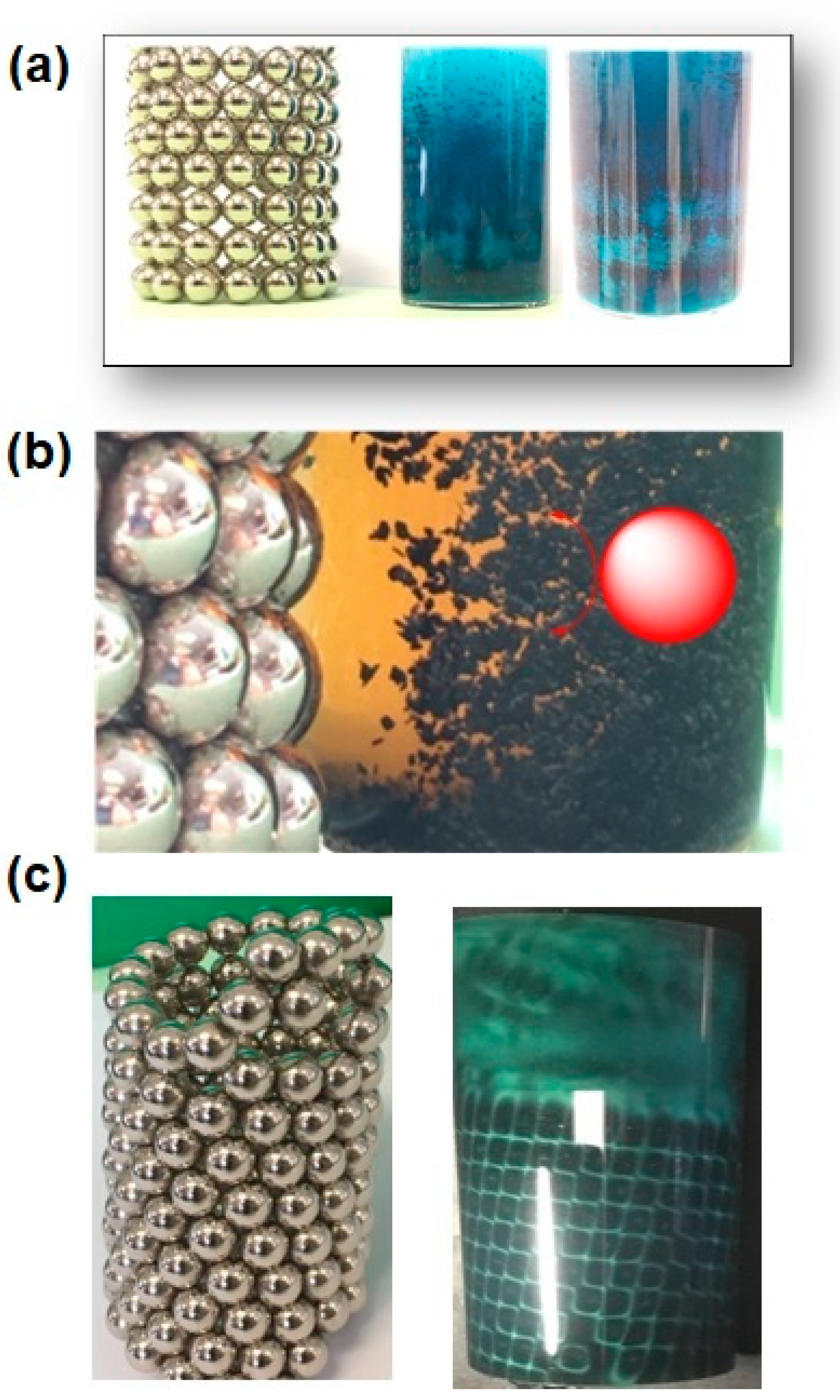
We began our crystallization studies using the formation of the dark green paramagnetic complex [Ni(II)(dppf)Cl2], (1), dppf = 1,1′-bis-(diphenylphosphino)ferrocene [35,36,37], since this ligand was readily available in bulk in our laboratories. The complexes were synthesized at room temperature from the ligand and a nickel precursor compound in the magnetic field so this is a synthesis in a magnetic field. In all magnetic fields we studied, this complex crystallized anisotropically, both in terms of crystal morphology and orientation. The typical magnetic field strengths used were 20–100 mT. In the first experiments, a crystallizing solution in a small glass vial was placed either inside a circular stack of three neodymium magnets (40/23 mm, height 6 mm, neodymium, N42, nickel-plated, 21 kg), Figure 1b, or touching a stack of rectangular magnets (block NdFeB, 30 × 15 × 6 mm, approx. 86.3 N), as shown in Figure 2c. These magnetic stacks will be called Magnetic Crystallization Towers (MCTs) from here on.
The chosen methodology was one we have used for a considerable period which is the room-temperature reaction of the yellow/orange anhydrous [Ni(II)(DME)Cl2] with the ligand dppf. Even though the precursor complex is poorly soluble in most organic solvents we have successfully used it in dichloromethane at room temperature to form many complexes. In this case, a dichloromethane slurry was used, and diethyl ether was added as an upper separate layer to facilitate the crystallization. The poor solubility means that the reaction is slow; however, we did not want to introduce water. Each of these results indicate a clear crystallization pattern was observed for this nickel complex. (The magnetic field strengths of the magnets were measured on the exterior of the stacked magnets using a gaussmeter; see Figure S2). The regions where the crystals were observed were those which showed the highest field strengths and the areas where no crystals formed were those of low or zero magnetic field. It should be mentioned at this point that we are looking at the formation of the well-known tetrahedral paramagnetic nickel (II) dichloride complex which has been structurally characterized [38]. This complex has been used as a catalyst for many years. (N.B. A nickel (I) chloride complex also has also been formed from the reaction of dppf and [Ni(1,5-COD)2] [39]). Encouraged by these results, we turned our attention to the crystallization of the new Zwitterionic complex [(C6H4-CH2PtBu2-2-C6H4-CH2P(H)tBu2)2Ni(II)Cl3] (2), which we were working on independently on a catalysis project. Again, initially the crystallizing solution of this complex was placed adjacent to the stacked magnets and in this case the crystallization patterns were even more defined, as shown in Figure 2. Smaller crystals were formed near the magnet and larger crystals formed further away indicating that more nucleation was taking place adjacent to the magnets. In addition, there were noticeably clear areas adjacent to the magnets where there was no nucleation. These correspond to low or zero magnetic field regions. Clearly ion migration through the solution towards the magnet must occur depleting the concentration away from the magnet. In these experiments, a concentration gradient occurs through time as the layered solvents mix; thus, under normal circumstances (in the absence of a magnetic field) crystals grow where the layers mix with no patterning. An example of this is shown in Supplementary Materials. Similarly, when [(C6H4-CH2PtBu2-2-C6H4-CH2P(H)tBu2)2Ni(II)Cl3] (2) was synthesized and crystallized with magnetic spheres placed around a vial of the crystallizing solution a distinct patterning was observed on the vial walls as shown in Figure 2a. This was replicated when dppf was reacted with [Ni(II)(DME)Cl2] to give [(Ni(II)(dppf)Cl2] (1). A close-up view of the latter complex is shown in Figure 2b. Again, a distinct pattering occurs with the crystal voids evident adjacent to where the spheres are in direct contact with one another. The pattern may be independently visualised using magnetic field paper, as shown in Figure 2c. For completeness, complex 2 was also recrystallised away from magnets and as expected no patterning was observed (Figure S13).
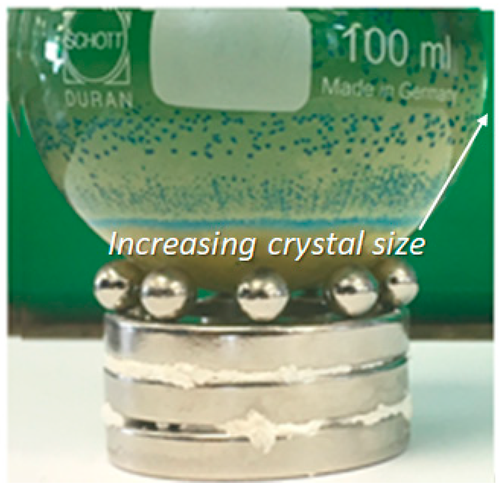
Since [(C6H4-CH2PtBu2-2-C6H4-CH2P(H)tBu2)2Ni(II)Cl3] (2) again exhibited the crystallisation properties particularly well, it was chosen to look at its crystallisation in a round-bottomed flask, placed on top of circular magnets as shown in Figure 3.
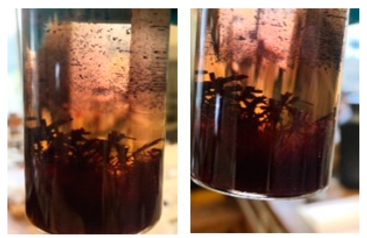
This turned out to be the most visually appealing result with concentric rings of crystals produced. Examination of the crystal patterns shows three concentric rings of crystals. The lower ring (closest to the magnets) has a high crystal concentration of small crystals indicative of high nucleation. The middle ring has slightly larger crystals which radiate linearly towards the top of the flask. The uppermost ring consists of larger crystals as they will begin to grow first as the initial diffusion of the ether occurs first in this area. These larger crystals, however, exhibit less patterning as they are the farthest from the magnets. At the base of the flask there are few crystals: this area corresponds to the lower magnetic field region in the centre of the ring magnet, and it is the last area to experience complete solvent mixing. In between the rings there are clear areas almost void of crystals. Buoyed by these results, several complexes were examined including diamagnetic complexes and similar properties were observed in each case. The simplest of these are [Ni(II)(dppe)Cl2] (3) (where dppe = bis 1,2-diphenylphosphinoethane) [40,41] and [Ni(II)(dppp)Cl2] (4) (where dppp = 1,3-bis-diphenylphosphinopropane) complexes which are red/brown [42,43]. It was found that these too crystallised in a well-defined 3D pattern. Although the product complexes are diamagnetic (square planar Ni(II) metal centres), it is important to remember that the patterning behaviour may be a result of diffusion of any intermediate complexes/ions which may be paramagnetic. When the magnets were placed directly into the crystallising solution, crystal rings were observed (Figure 4a).
In some cases where a very dense deeply coloured solution crystallises in a vial, the human eye cannot detect an effect, but we observe that shining light through the sample reveals the crystallisation patterns (Figure 4b). Again, reiterating the point, it is important to state that the crystallisation phenomenon may be associated with the nickel precursor and thus the formation of a diamagnetic product does not necessarily mean that the phenomena apply to diamagnetic complexes. When the ligand triphos (triphos = tris-(methyldiphenylphosphino)methane) [44,45,46,47] was used, we observed that crystals of [Ni(II)P,P-(ƞ2-triphos)Cl2] (5) formed a grid pattern in the vial following field lines (Figure 5).
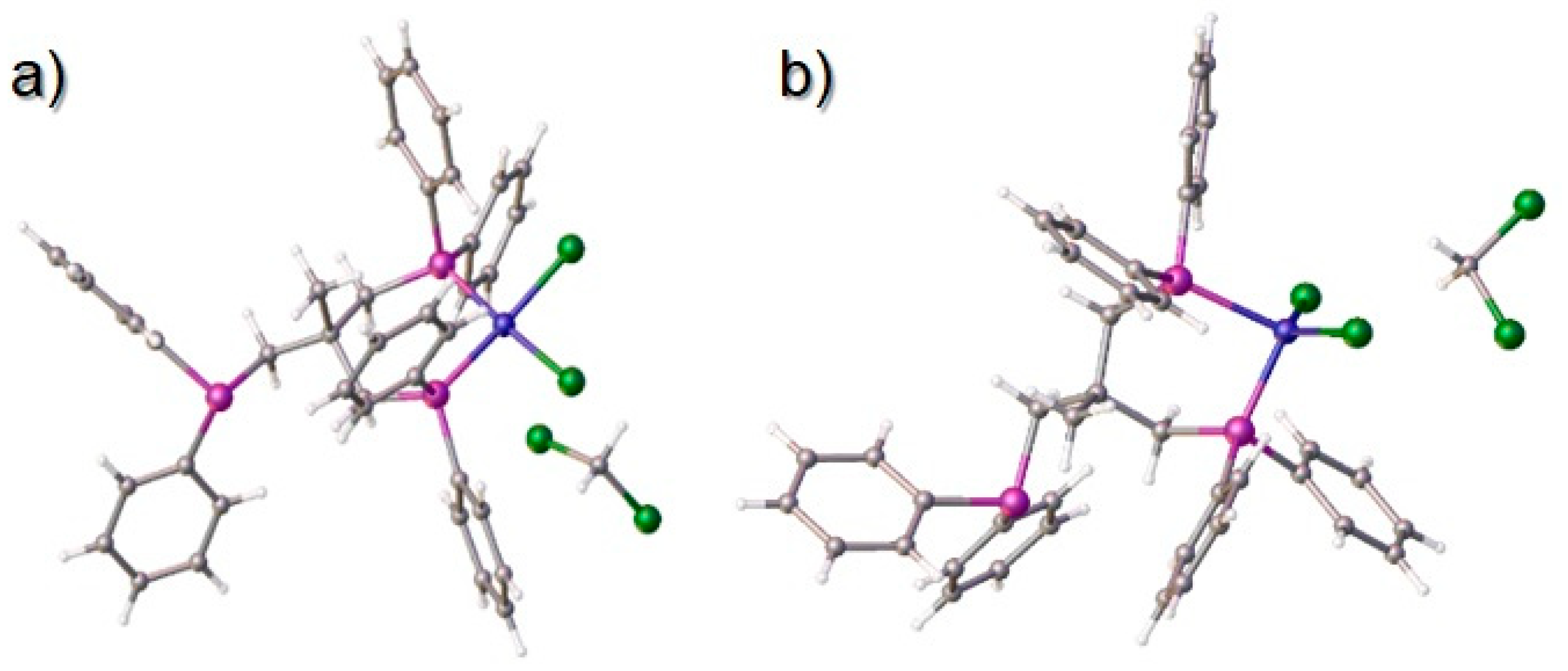
The crystals of ‘NiTriphos’ were shown to have a disordered nickel ion centre, with a mixture of either tetrahedral or square planar geometry (at a 12:88 ratio), along with an associated disordered DCM solvate to compliment filling the cavity. (The split forms are shown in Figure 6). The unit cell is effectively a match with the known square planar complex [48] which although recrystallized from THF, shows no solvent in the structure but does contain suitable void spaces. Thus, it does appear as though the magnetic field is inducing some change of the nickel centres into the tetrahedral geometry. Two further crystals (TriphosNiCl2_C2 and TriphosNiCl2_C3) have been attempted from that same batch which gave the same unit cell, and upon solving produced slightly different ratios (16:84 and 13:87)), showing that there is a little variation in the effect of the magnetic field as to the formation that occurs). In one final case, we looked at the formation and crystallisation of [Ni(II)(PPh3)2Cl2] (6) [49,50,51,52,53].
It is well known that it may form both tetrahedral and square planar complexes depending on the nature of the solvent used. We would expect that the square planar complex would form because we are using dichloromethane as solvent, but this apparently simple preparation turned out to be the most complex. We studied the formation over 20 times using even more powerful magnets (when we used large block magnets, a single magnet or a pair of magnets on opposite sides of the sample was used as we considered it too dangerous to assemble a magnetic stack) and on many different scales; the crystallising solution indicated the presence of many powdered products in addition to small amounts of crystalline material. The solution was always violet-coloured, yet an off-white precipitate also formed which we initially thought was ligand. However, this powder was stacked on the tube wall nearest the magnets, and it could be physically moved inside the vial by moving the external magnets and it was strongly attracted to the external magnets in real time. This manifestation of bulk magnetic properties was an intriguing observation. The nature of this white powder is unknown and thus clearly this is an avenue of research which requires further exploration. Additional photographs of the crystallisation these complexes are included in Supplementary Materials.

2.2. Part B: Crystallising Heptanuclear Nickel and Zinc Complexes Using MCTs

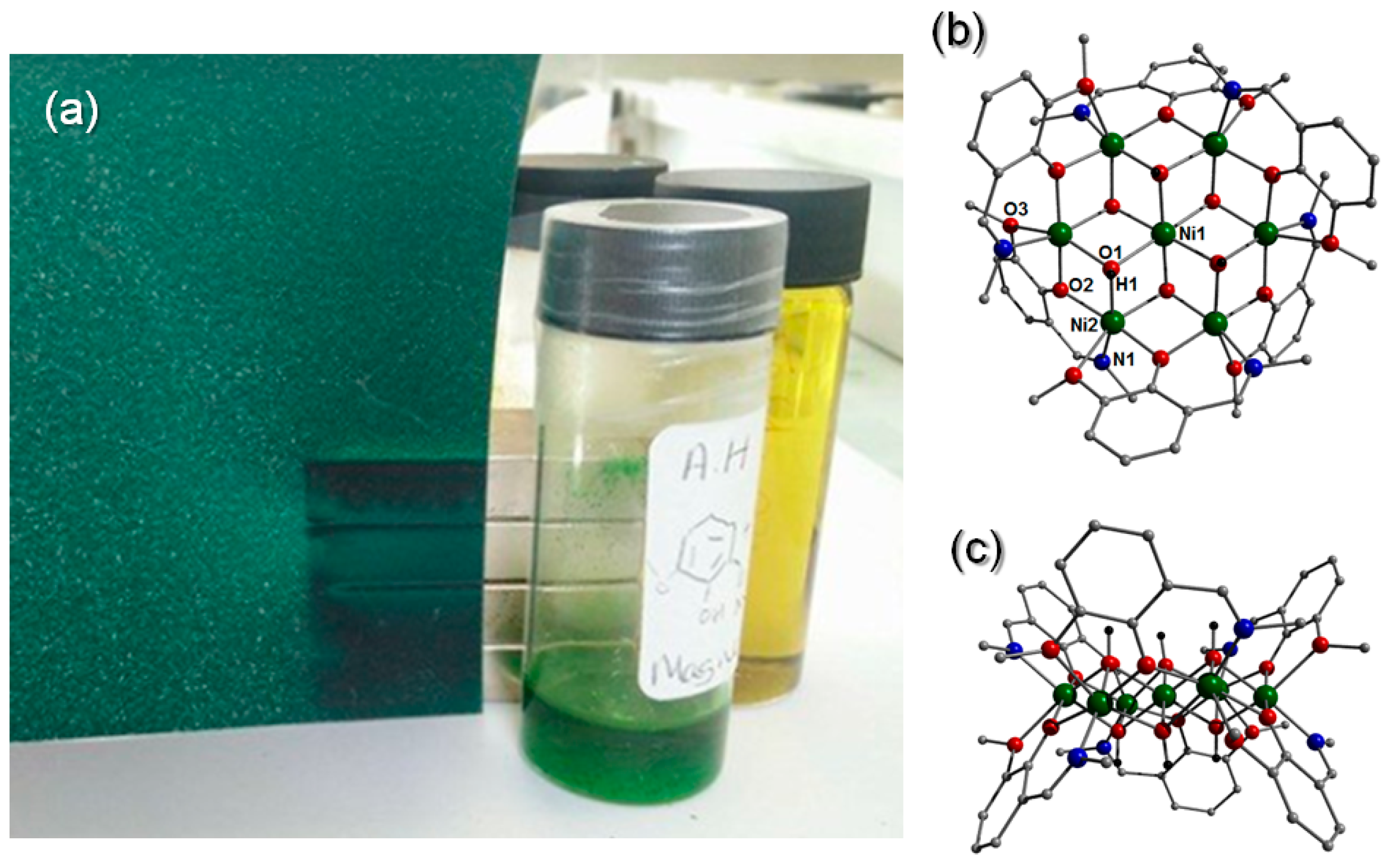
It was decided to move away from organometallic complexes and concentrate on 3d and 4f metal complexes. More specifically, a methanolic solution of the pseudo metallocalix[6]arene [(MeOH)2⊂Ni(II)7(OH)6(L)6](NO3)2 (7; L = LH = 2-iminomethyl-6-methoxyphenol; CCDC = 758,960; ref = [36]) was placed next to an MCT comprising four neodymium (NdFeB) block magnets (60 × 30 × 15 mm). Over a period of 2–3 days, the product (complex 7) crystallised in a patterned orientation preferentially along the MCT/sample vial interface and along regions of higher magnetic field as highlighted using magnetic paper (50 mm × 50 mm) and illustrated in Figure 7. To show that this is a paramagnetic effect, magnetic crystallisation studies on the analogous diamagnetic Zn(II) complex ([(MeOH)2⊂Zn(II)7(OH)6(L)6](NO3)2; (8); CCDC = 758,961) [34] were carried out and were found to give no preferential crystal growth distribution. These observations can be more clearly observed via the video clip (see Supplementary Materials).
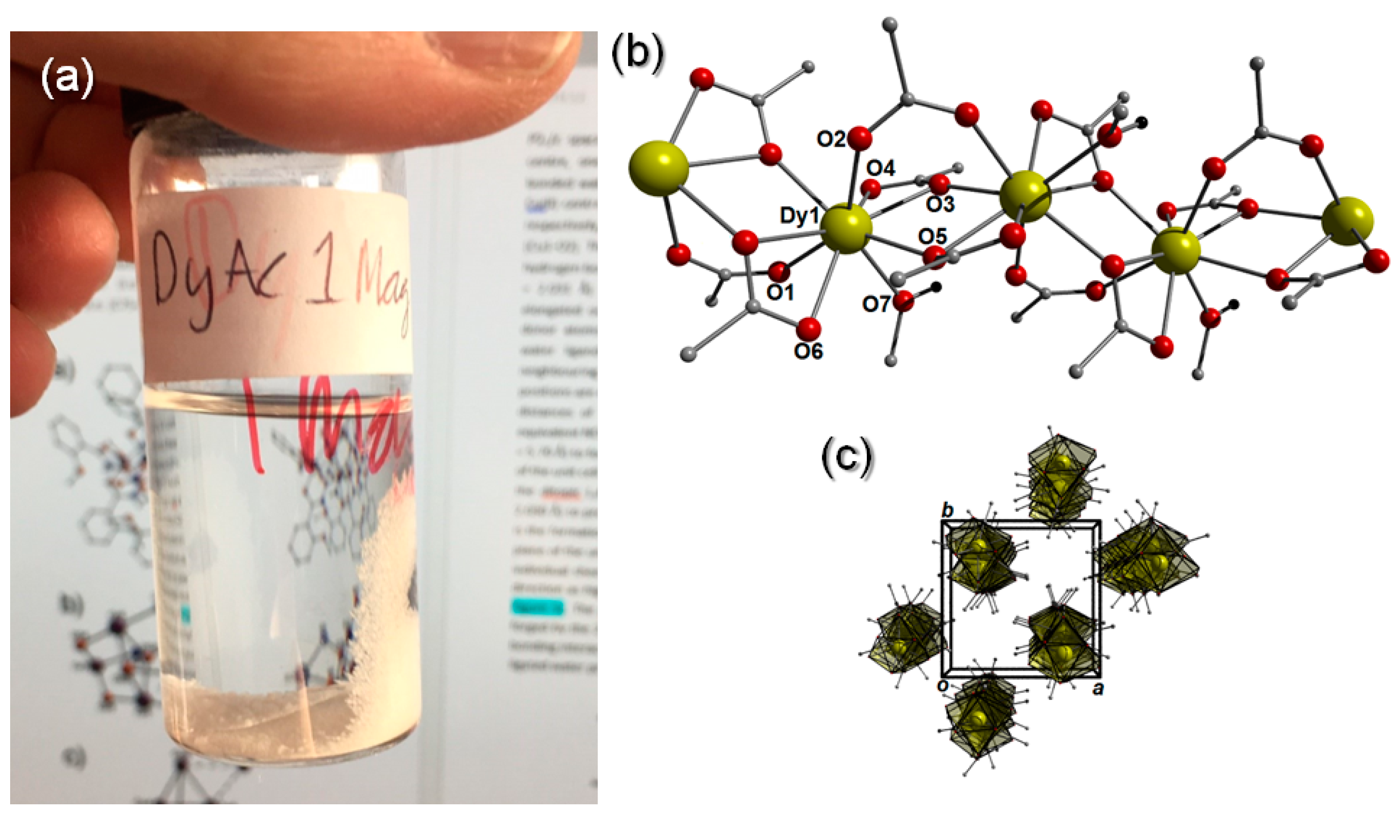
For the third and final example, we present the directed crystallisation of the previously reported 1-D coordination polymer [Dy(III)(OAc)3(MeOH)]n [54]. This was carried out by dissolving the initially prepared dimeric complex [Dy(III)2(OAc)6(H2O)4].4H2O in methanol to give a 17.46 mM solution of the resultant polymer. This methanolic solution was placed next to an MCT and over the space of 24 h a white polycrystalline sample of [Dy(III)(OAc)3(MeOH)]n crystallised preferentially at the sample vial/MCT interface as highlighted in Figure 8a (see accompanying video clip in Supplementary Materials. An identical solution was crystallised away from the MCT, giving a uniform layer of the polymer at the bottom of the sample vial. As shown in Figure 8b,c, single-crystal X-ray diffraction data on this complex (CCDC = 2424601) confirmed polymer formation (CCDC of original structure = 727044; for a comparison of the unit cells see Table S1).

3. Materials and Methods

The Materials and Methods are described in Supplementary Materials which includes figures showing the experimental layouts and visuals of the magnets used in the experiments. We should point out here that great care must be taken when assembling MCTs and hand protection should be worn. It is not recommended to assemble multiple high-power neodymium magnets.

4. Conclusions

The mechanism of the crystallisation process is of general interest. Clearly, the diffusion and migration processes are of interest in addition to crystal nucleation and growth. In some test reactions, it was possible to observe bulk diffusion and solution perturbations, caused directly by external magnets; however, these tended to be using very strong magnets, rather than the ones described here. The nucleation process is of special interest as the initial crystallisations clearly must be directly affected by the magnetic fields—the locations of the highest concentrations of metals ions in solution are likely to give rise to preferential nucleation. Thereafter, the actual crystal growth also may be affected by the external field. At this point there are no general rules except that the phenomenon of crystal patterning seems to be a general one. These findings are, to the best of our knowledge, only the second report concerning the crystallisation of paramagnetic complexes using commercially available Nd magnets and the first to construct purpose-built MCTs (and other elaborate set-ups) to aid the crystallisation process [6]. We are currently working on directing metal surface attachment of pertinent magnetic materials through the careful placement of a metal plate within the required paramagnetic solution and parallel with our MCT structure. We aim to control this surface coverage by using suitable ligands to construct target magnetic complexes. For instance, ligands with thiol or thioacetate groups at their periphery will be directed in a controlled manner via favoured Ag–S bond formation, effectively anchoring the metal complex to the gold plate. We envisage application in the surface attachment of (for instance) magnetic coolant materials as required for their effective operation. We will also crystallise known magnetically interesting materials (e.g., chiral magnetic complexes) in the presence of our MCTs to probe any resultant structural changes as even minute modifications can cause significant changes in magnetic behaviour.

Supplementary Materials

The following supporting information can be downloaded at: https://www.mdpi.com/article/10.3390/inorganics13040117/s1, A total of 20 figures and 8 tables, Figures S1–S20, Tables S1–S8, are available in the supporting information file. Video S1: Dy-complex crystallization. References [55,56,57,58,59] are cited in the Supplementary Materials.

Author Contributions

I.R.B.: manuscript—writing, editing and proofing, experimental work, project conception. R.M.W.: experimental work. A.H.: experimental work. P.N.H.: crystallography, writing and proofing. S.J.C.: crystallography overseer. L.F.J.: manuscript—writing, editing and proofing, experimental work, project conception. All authors have read and agreed to the published version of the manuscript.

Funding

We thank EPSRC for funding the National Crystallography Service (Southampton). No external funding was received for the synthetic work.

Institutional Review Board Statement

Not applicable.

Informed Consent Statement

Not applicable.

Data Availability Statement

Data are contained within the Supplementary Materials.

Acknowledgments

We would like to thank Patrick Murphy, now Emeritus, of Bangor University for provision of time and Zahraa S. Al-Taie of Al-Nahrain University, for additional help with photographing experimental set-ups.

Conflicts of Interest

The authors declare no conflicts of interest.

References

  1. Dechambenoit, P.; Long, J.R. Microporous magnets. Chem. Soc. Rev. 2011, 40, 3249–3265. [Google Scholar] [CrossRef] [PubMed]
  2. Thompson, L.K.; Waldmann, O.; Xu, Z. Magnetic Properties of Self-Assembled [2 × 2] and [3 × 3] Grids. In Magnetism: Molecules to Materials IV: Nanosized Magnetic Materials; Miller, J.S., Drillon, M., Eds.; Wiley-VCH: Weinheim, Germany, 2003. [Google Scholar] [CrossRef]
  3. Steiner, U.E.; Ulrich, T. Magnetic field effects in chemical kinetics and related phenomena. Chem. Rev. 1989, 89, 51–147. [Google Scholar] [CrossRef]
  4. Yan, E.-K.; Zhang, C.-Y.; He, J.; Yin, D.-C. An Overview of Hardware for Protein Crystallization in a Magnetic Field. Int. J. Mol. Sci. 2016, 17, 1906. [Google Scholar] [CrossRef] [PubMed]
  5. Perlepe, P.S.; Maniaki, D.; Pilichos, E.; Katsoulakou, E.; Perlepes, S.P. Smart Ligands for Efficient 3d-, 4d- and 5d-Metal Single-Molecule Magnets and Single-Ion Magnets. Inorganics. 2020, 8, 39. [Google Scholar] [CrossRef]
  6. Tassinari, F.; Steidel, J.; Paltiel, S.; Fontanesi, C.; Lahav, M.; Paltiel, Y.; Naaman, R. Enantioseparation by crystallization using magnetic substrates. Chem. Sci. 2019, 10, 5246–5250. [Google Scholar] [CrossRef] [PubMed]
  7. Potticary, J.; Hall, C.L.; Guo, R.; Price, S.L.; Hall, S.R. On the Application of Strong Magnetic Fields during Organic Crystal Growth. Cryst. Growth Des. 2021, 21, 6254–6265. [Google Scholar] [CrossRef]
  8. Laget, V.; Hornick, C.; Rabu, P.; Drillon, M.; Ziessel, R. Molecular magnets: Hybrid organic–inorganic layered compounds with very long-range ferromagnetism. Coord. Chem. Rev. 1998, 178–180, 1533–1553. [Google Scholar] [CrossRef]
  9. Coronado, E. Molecular magnetism: From chemical design to spin control in molecules, materials and devices. Nat. Rev. Mater. 2020, 5, 87–104. [Google Scholar] [CrossRef]
  10. Chen, Y.-C.; Tong, M.-L. Single-molecule magnets beyond a single lanthanide ion: The art of coupling. Chem. Sci. 2022, 13, 8716–8726. [Google Scholar] [CrossRef] [PubMed]
  11. Woodruff, D.N.; Winpenny, R.E.P.; Layfield, R.A. Lanthanide single-molecule magnets. Chem. Rev. 2013, 113, 5110–5148. [Google Scholar] [CrossRef]
  12. Kozhevnikov, V. Meissner Effect: History of Development and Novel Aspects. J. Supercond. Nov. Magn. 2021, 34, 1979–2009. [Google Scholar] [CrossRef]
  13. Essén, H.; Fiolhais, M.C.N. Meissner effect, diamagnetism, and classical physics—A review. Am. J. Phys. 2012, 80, 164–169. [Google Scholar] [CrossRef]
  14. Wilcox, J.A.; Grant, M.J.; Malone, L.; Putzke, C.; Kaczorowski, D.; Wolf, T.; Hardy, F.; Meingast, C.; Analytis, J.G.; Chu, J.-H.; et al. Observation of the non-linear Meissner effect. Nature Commun. 2022, 13, 1201. [Google Scholar] [CrossRef]
  15. Liu, X.; Pollner, B.; Paulitsch-Fuchs, A.H.; Fuchs, E.C.; Dyer, N.P.; Loiskandl, W.; Lass-Flörl, C. Investigation of the effect of sustainable magnetic treatment on the microbiological communities in drinking water. Environ. Res. 2022, 213, 113628. [Google Scholar] [CrossRef] [PubMed]
  16. Lin, L.; Jiang, W.; Xu, P. A critical review of the application of electromagnetic fields for scaling control in water systems: Mechanisms, characterization, and operation. NPJ Clean Water. 2020, 3, 25. [Google Scholar] [CrossRef]
  17. Coey, J.M.D.; Cass, S. Magnetic water treatment. J. Magn. Mag. Mater. 2000, 209, 71–74. [Google Scholar] [CrossRef]
  18. Alimi, F.; Tlili, M.M.; Ben Amor, M.; Maurin, G.; Gabrielli, C. Influence of magnetic field on calcium carbonate precipitation. Chem. Eng. Process. Process Intensif. 2009, 48, 1327–1332. [Google Scholar] [CrossRef]
  19. Wakayama, N.I. Effects of a Strong Magnetic Field on Protein Crystal Growth. Cryst. Growth Des. 2003, 3, 17–24. [Google Scholar] [CrossRef]
  20. Nakamura, A.; Ohtsuka, J.; Kashiwagi, T.; Numoto, N.; Hirota, N.; Ode, T.; Okada, H.; Nagata, K.; Kiyohara, M.; Suzuki, E.; et al. In-situ and real-time growth observation of high-quality protein crystals under quasi-microgravity on earth. Sci. Rep. 2016, 6, 22127. [Google Scholar] [CrossRef]
  21. Yin, D.-C. Protein crystallization in a magnetic field. Prog. Cryst. Growth Charact. Mat. 2015, 61, 1–26. [Google Scholar] [CrossRef]
  22. Moreno, A.; Quiroz-Garcia, B.; Yokaichiya, F.; Stojanoff, V.; Rudolph, P. Protein crystal growth in gels and stationary magnetic fields. Cryst. Res. Technol. 2007, 42, 231–236. [Google Scholar] [CrossRef]
  23. Maki, S.; Hagiwara, M. Contactless crystallization method of protein by a magnetic force booster. Sci. Rep. 2022, 12, 17287. [Google Scholar] [CrossRef]
  24. Atkinson, M.B.J.; Bwambok, D.K.; Chen, J.; Chopade, P.D.; Thuo, M.M.; Mace, C.R.; Mirica, K.A.; Kumar, A.A.; Myerson, A.S.; Whitesides, G.M. Using Magnetic Levitation to Separate Mixtures of Crystal Polymorphs. Angew. Chem. Int. Ed. 2013, 52, 10208–10211. [Google Scholar] [CrossRef] [PubMed]
  25. Abrahamsson, C.K.; Nagarkar, A.; Fink, M.J.; Preston, D.J.; Ge, S.; Bozenko, J.S., Jr.; Whitesides, G.M. Analysis of Powders Containing Illicit Drugs Using Magnetic Levitation. Angew. Chem. Int. Ed. Engl. 2020, 132, 884–891. [Google Scholar] [CrossRef]
  26. Hu, L.; Wang, Z.; Wang, H.; Qu, Z.; Chen, Q. Tuning the structure and properties of a multiferroic metal-organic-framework via growing under high magnetic fields. RSC Adv. 2018, 8, 13675–13678. [Google Scholar] [CrossRef] [PubMed]
  27. Hong, D.L.; Luo, Y.-H.; He, Z.-T.; He, C.; Zheng, Z.-Y.; Su, S.; Wang, C.; Wang, J.-Y.; Chen, C.; Sun, B.-W. Molecular Disorder Induced by the Application of an External Magnetic Field during Crystal Growth. J. Phys. Chem. 2019, 123, 15230–15235. [Google Scholar] [CrossRef]
  28. Meihaus, K.R.; Corbey, J.F.; Fang, M.; Ziller, J.W.; Long, J.R.; Evans, W.J. Influence of an Inner-Sphere K+ Ion on the Magnetic Behavior of N23–Radical-Bridged Dilanthanide Complexes Isolated Using an External Magnetic Field. Inorg. Chem. 2014, 53, 3099–3107. [Google Scholar] [CrossRef] [PubMed]
  29. Higgins, R.F.; Cheisson, T.; Cole, B.E.; Manor, B.C.; Carroll, P.J.; Schelter, E.J. Magnetic Field Directed Rare-Earth Separations. Angew. Chem. Int. Ed. 2019, 58, 2–8. [Google Scholar] [CrossRef]
  30. Banerjee-Ghosh, K.; Dor, O.B.; Tassinari, F.; Capua, E.; Yochelis, S.; Capua, A.; Yang, S.-H.; Parkin, S.S.P.; Sarkar, S.; Kronik, L.; et al. Separation of enantiomers by their enantiospecific interaction with achiral magnetic substrates. Science 2018, 360, 1331–1334. [Google Scholar] [CrossRef]
  31. Garcés-Pineda, F.A.; Blasco-Ahicart, M.; Nieto-Castro, D.; López, N.; Galán-Mascarós, J.R. Direct magnetic enhancement of electrocatalytic water oxidation in alkaline media. Nat. Energy 2019, 4, 519–525. [Google Scholar] [CrossRef]
  32. Clevenger, A.L.; Stolley, R.M.; Aderibigbe, J.; Louie, J. Trends in the Usage of Bidentate Phosphines as Ligands in Nickel Catalysis. Chem. Rev. 2020, 120, 6124–6196. [Google Scholar] [CrossRef] [PubMed]
  33. Meally, S.T.; McDonald, C.; Karotsis, G.; Papaefstathiou, G.S.; Brechin, E.K.; Dunne, P.W.; McArdle, P.; Power, N.P.; Jones, L.F. A family of double-bowl pseudo metallocalix[6]arene discs. Dalton Trans. 2010, 39, 4808–4816. [Google Scholar] [CrossRef]
  34. Meally, S.T.; Karotsis, G.; Brechin, E.K.; Papaefstathiou, G.S.; Dunne, P.W.; McArdle, P.; Jones, L.F. Planar [Ni7] discs as double-bowl, pseudo metallacalix[6]arene host cavities. CrystEngComm 2010, 12, 59–63. [Google Scholar] [CrossRef]
  35. Colacot, T.J. Ferrocenyl Phosphine Complexes of the Platinum Metals in Non-Chiral Catalysis. Their Applications in Carbon—Carbon and Carbon—Heteroatom Coupling Reactions. Platin. Met. Rev. 2001, 45, 22–30. [Google Scholar] [CrossRef]
  36. Young, D.J.; Chienb, S.W.; Hor, T.S.A. 1,1′-Bis(diphenylphosphino)ferrocene in functional molecular materials. Dalton Trans. 2012, 41, 12655–12665. [Google Scholar] [CrossRef] [PubMed]
  37. Nataro, C.; Campbell, A.N.; Ferguson, M.A.; Incarvito, C.D.; Rheingold, A.L.; Group 10 metal compounds of 1,1′-bis(diphenylphosphino)ferrocene (dppf) and 1,1′-bis(diphenylphosphino)ruthenocene: A structural and electrochemical investigation. X-ray structures of [MCl2(dppr)] (M=Ni, Pd). J. Organometal. Chem. 2003, 673, 47–55. [Google Scholar] [CrossRef]
  38. Casellato, U.; Ajó, D.; Valle, G.; Corain, B.; Longato, B.; Graziani, R. Heteropolymetallic complexes of 1,1′-bis(diphenylphosphino) ferrocene (dppf). II. Crystal structure of dppf and NiCl2(dppf). J. Cryst. Spect. Res. 1988, 18, 583–590. [Google Scholar] [CrossRef]
  39. Greaves, M.E.; Ronson, T.O.; Lloyd-Jones, G.C.; Maseras, F.; Stephen Sproules, S.; Nelson, D.J. Unexpected Nickel Complex Speciation Unlocks Alternative Pathways for the Reactions of Alkyl Halides with dppf-Nickel(0). ACS Catal. 2020, 10, 10717–10725. [Google Scholar] [CrossRef] [PubMed]
  40. Davison, J.C.; Foreman, M.R.S.-J.; Howie, R.A.; Plater, M.J.; Skakle, J.M.S. New Polymorph, Form C, of [1,2-Bis(diphenylphosphino)ethane]dichloronickel(II). Acta Crystallogr. C 2001, 57, 690–693. [Google Scholar] [CrossRef]
  41. Busby, R.; Hursthouse, M.B.; Jarrett, P.S.; Lehmann, C.W.; Malik, K.M.A.; Phillips, C. Dimorphs of [1,2-bis(diphenylphosphino)ethane]dichloronickel(II). J. Chem. Soc. Dalton Trans. 1993, 3767–3770. [Google Scholar] [CrossRef]
  42. Bomfim, J.A.S.; de Souza, F.P.; Filgueiras, C.A.L.; de Sousa, A.G.; Gambardella, M.T.P. Diphosphine complexes of nickel: Analogies in molecular structures and variety in crystalline arrangement. Polyhedron 2003, 22, 1567–1573. [Google Scholar] [CrossRef]
  43. Van Hecke, G.R.; Horrocks, W.D. Ditertiary Phosphine Complexes of Nickel. Spectral, Magnetic, and Proton Resonance Studies. A Planar-Tetrahedral Equilibrium. Inorg. Chem. 1966, 5, 1968–1974. [Google Scholar] [CrossRef]
  44. Davis, R.; Fergusson, J.E. Coordination chemistry of 1,1,1-tris-(bisphenylphosphinomethyl) ethane. II. Four and five coordinate complexes of cobalt(II) and nickel(II). Inorg. Chim. Acta 1970, 4, 23–28. [Google Scholar] [CrossRef]
  45. de Assis, E.F.; Filgueiras, C.A.L. 1,1,1-Tris(diphenylphosphinemethyl)ethane complexes of nickel and platinum with tin. Transit. Met. Chem. 1994, 19, 484–486. [Google Scholar] [CrossRef]
  46. Dapporto, P.; Midollini, S.; Orlandini, A.; Sacconi, L. Complexes of cobalt, nickel, and copper with the tripod ligand 1,1,1-tris(diphenylphosphinomethyl)ethane (p3). Crystal structures of the [Co(p3)(BH4)] and [Ni(p3)(SO2)] complexes. Inorg. Chem. 1976, 15, 2768–2774. [Google Scholar] [CrossRef]
  47. Kandiah, M.; McGrady, G.S.; Decken, A.; Sirsch, P. [(Triphos)Ni(η2-BH4)]: An Unusual Nickel(I) Borohydride Complex. Inorg. Chem. 2005, 44, 8650–8652. [Google Scholar] [CrossRef] [PubMed]
  48. Bianchini, C.; Meli, A.; Orlandini, A.; Sacconi, L. Cobalt (II) and nickel (II) complexes with 1,1-bis (diphenylphosphinomethyl)-1-diphenylphosphino-ethylethane, atriphos, and 1,1,1-tris(diethylphosphinomethyl)ethane, etriphos. Crystal structures of the trinuclear complexes [Co3(atriphos)2Cl6] and [Ni3(etriphos)2Cl6]·2 CHCl3. J. Organometa Chem. 1981, 209, 29–231. [Google Scholar] [CrossRef]
  49. Kato, H.; Yorita, K.; Kato, Y. Structural lnterconversions of Dichlorobis(triphenylphosphine) nickel(II) in Various Solvents. Bull. Chem. Soc. Jpn. 1979, 52, 2465–2473. [Google Scholar] [CrossRef]
  50. Batsanov, A.S.; Howard, J.A. Trans-Dichlorobis (triphenylphosphine) nickel (II) bis (dichloromethane) solvate: Redetermination at 120 K. Acta Cryst. 2001, 57, m308–m309. [Google Scholar] [CrossRef]
  51. Garton, G.; Henn, D.E.; Powell, H.M.; Venanzi, L.M. Tetrahedral nickel(II) complexes and the factors determining their formation. Part V. The tetrahedral co-ordination of nickel in dichlorobistriphenylphosphinenickel. J. Chem. Soc. 1963, 3625–3629. [Google Scholar] [CrossRef]
  52. Brammer, L.; Stevens, E.D. Structure of dichlorobis(triphenylphosphine)nickel(II). Acta Cryst. 1989, 45, 400–403. [Google Scholar] [CrossRef]
  53. Corain, B.; Longato, B.; Angeletti, R.; Valle, G. trans-[Dichlorobis(triphenylphosphine)nickel(II)]·(C2H4Cl2)2: A clathrate of the allogon of venanzi’s tetrahedral complex. Inorg. Chim. Acta 1985, 104, 15–18. [Google Scholar] [CrossRef]
  54. Zheng, Y.-Z.; Lan, Y.; Wernsdorfer, W.; Anson, C.E.; Powell, A.K. Polymerisation of the Dysprosium Acetate Dimer Switches on Single-Chain Magnetism. Chem. Eur. J. 2009, 15, 12566–12570. [Google Scholar] [CrossRef]
  55. CrysAlisPro Software System, versions 1.171.39.28e, 1.171.39.31c and 1.171.44.91; Rigaku Oxford Diffraction: The Woodlands, TX, USA, 2025.
  56. Dolomanov, O.V.; Bourhis, L.J.; Gildea, R.J.; Howard, J.A.K.; Puschmann, H. Olex2: A complete structure solution, refinement and analysis program. J. Appl. Cryst. 2009, 42, 339–341. [Google Scholar] [CrossRef]
  57. Sheldrick, G.M. Crystal structure refinement with ShelXL. Acta Cryst. 2015, C71, 3–8. [Google Scholar]
  58. Sheldrick, G.M. ShelXT-Integrated space-group and crystal-structure determination. Acta Cryst. 2015, A71, 3–8. [Google Scholar]
  59. Ward, L.G.L.; Pipal, J.R. Anhydrous Nickel(II) Halides and their Tetrakis(ethanol) and 1,2-Dimethoxyethane Complexes. Inorg. Synth. 1972, 13, 154–164. [Google Scholar] [CrossRef]
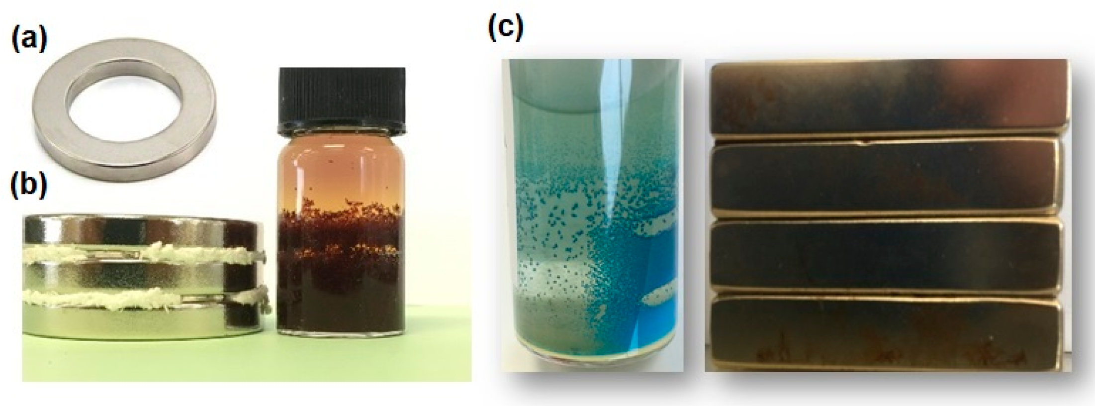
Figure 1. (a) A typical circular commercially available neodymium magnet. (b) Crystallisation pattern of [Ni(II)(dppf)Cl2] (1), inside a stack of three circular neodymium magnets. (c) A vial containing a crystallising solution of [(C6H4-(CH2PtBu2)2-2-C6H4-CH2P(H)tBu2)2Ni(II)Cl3] (2) placed adjacent to a stack of four neodymium magnets. Smaller crystals are observed next to the magnet and distinct areas of little or no crystallisation are apparent.
Inorganics 13 00117 g001
Figure 2. (a) [(C6H4-CH2PtBu2-2-C6H4-CH2P(H)tBu2)2NiCl3] (2) crystallised in a vial surrounded by magnetic spheres. (b) A close-up view of the pattern obtained in the crystallisation of [Ni(dppf)Cl2] (1) in a vial surrounded by magnetic spheres (the red inset shows the size of the spheres which were behind crystals). (c) Visualisation of magnetic field pattern created by spheres using magnetic field paper.
Inorganics 13 00117 g002
Figure 3. Crystallisation of [(C6H4-CH2PtBu2-2-C6H4-CH2P(H)tBu2)2Ni(II)Cl3] (2) in a round-bottomed flask on top of an array of circular and spherical magnets. Notice the concentric rings of crystals and the increase in the crystal size from top to bottom. (N.B. The magnetic fields’ strengths may be seen in Supplementary Materials).
Inorganics 13 00117 g003
Figure 4. (a) Crystallisation of [Ni(II)(dppp)Cl2] (3) around a circle of magnets. (b) Crystallisation of [Ni(II)(dppp)Cl2] (4) in a vial within circular magnets, using light to show the crystallisation pattern.
Inorganics 13 00117 g004
Figure 5. Formation and crystallization of [Ni(II)P,P-(ƞ2-triphos)Cl2] (5) showing the crystals reaching into the solution following field line patterns. These crystals form suspended fragile grids which collapse on agitation.
Inorganics 13 00117 g005
Figure 6. Square planar (a) and tetrahedral (b) complexes of Ni(II)(triphos)2Cl2] (5) (CCDC = 2422622). Full crystallographic data are given in Supplementary Materials. Colour code: Ni (blue), P (purple), Cl (green) C (grey) and H (white).
Inorganics 13 00117 g006
Figure 7. (a) A Magnetic Crystallisation Tower (MCT) alongside a sample of [(MeOH)2⊂Ni(II)7(OH)6(L)6](NO3)2 (7) (b,c), whose green hexagonal crystals are forming in alignment with the high magnetic field regions of the MCT. These regions are highlighted by the dark domains demonstrated using magnetic paper. Colour code: Ni (green), O (red), N (blue) and C (grey). Hydrogen atoms have been omitted for clarity.
Inorganics 13 00117 g007
Figure 8. (a) Photograph of the localised crystallisation of the coordination polymer [Dy(III)(OAc)3(MeOH)]n (9) alongside a crystal structure representation (b) and its corresponding packing arrangements (c). Colour code: Dy (yellow), O (red), C (grey) and H (black). Most hydrogen atoms have been omitted for clarity.
Inorganics 13 00117 g008
Disclaimer/Publisher’s Note: The statements, opinions and data contained in all publications are solely those of the individual author(s) and contributor(s) and not of MDPI and/or the editor(s). MDPI and/or the editor(s) disclaim responsibility for any injury to people or property resulting from any ideas, methods, instructions or products referred to in the content.