
Probe-Sonicated Synthesis of CuO–ZnO Hybrid Nanocomposite for Photocatalytic and Supercapacitor Applications

 ,
,  ,
,  ,
,  ,
,
Abstract
:1. Introduction
2. Materials and Methods
2.1. Synthesis of the CuO–ZnO Hybrid Nanocomposite
2.2. Preparation of Working Electrodes
2.3. Electrochemical Measurements
2.4. Characterizations
3. Results and Discussion
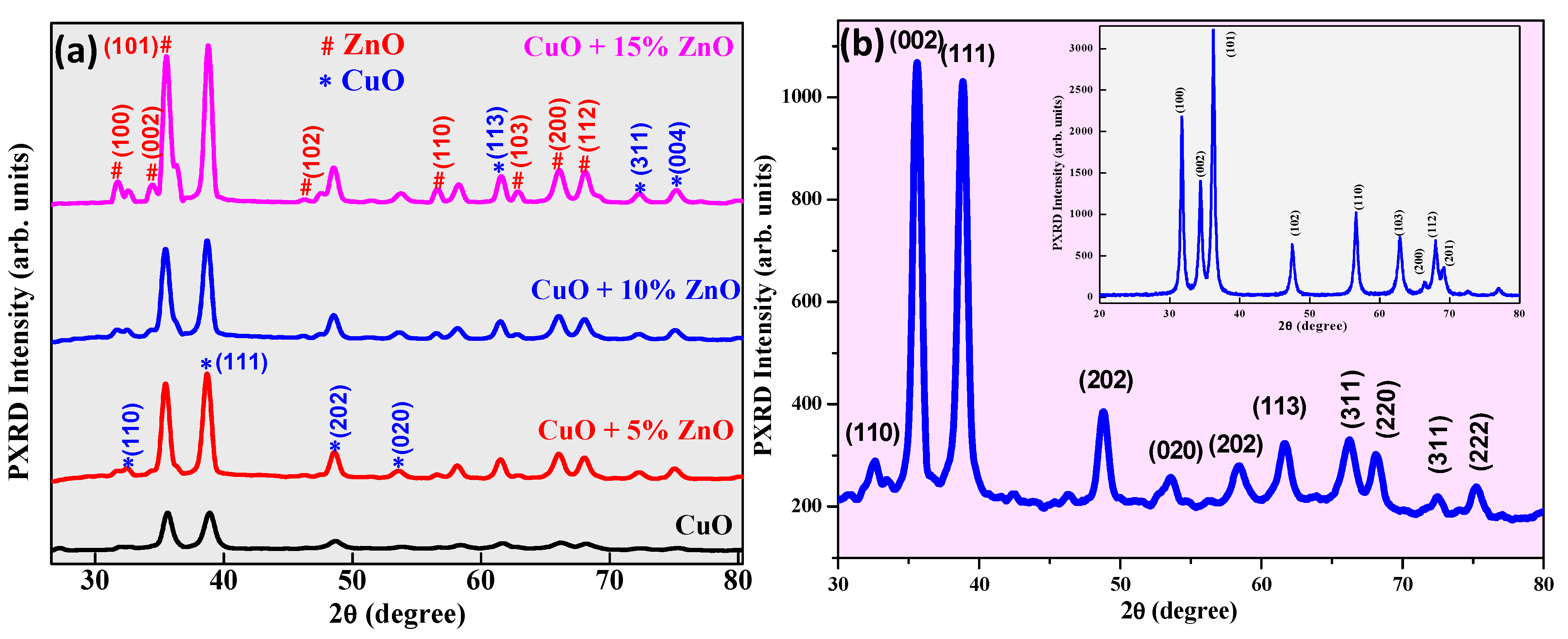
3.1. PXRD Analysis
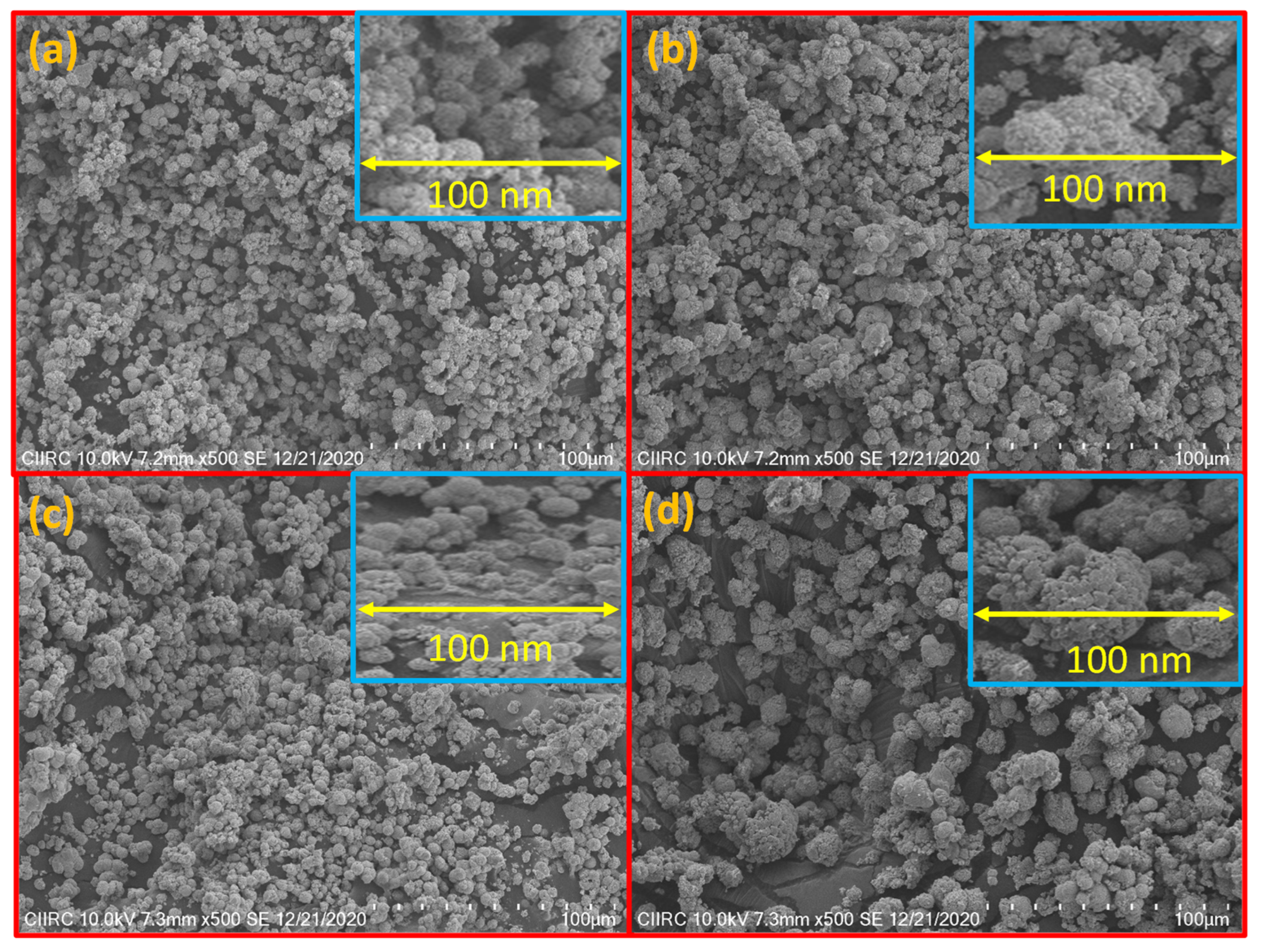
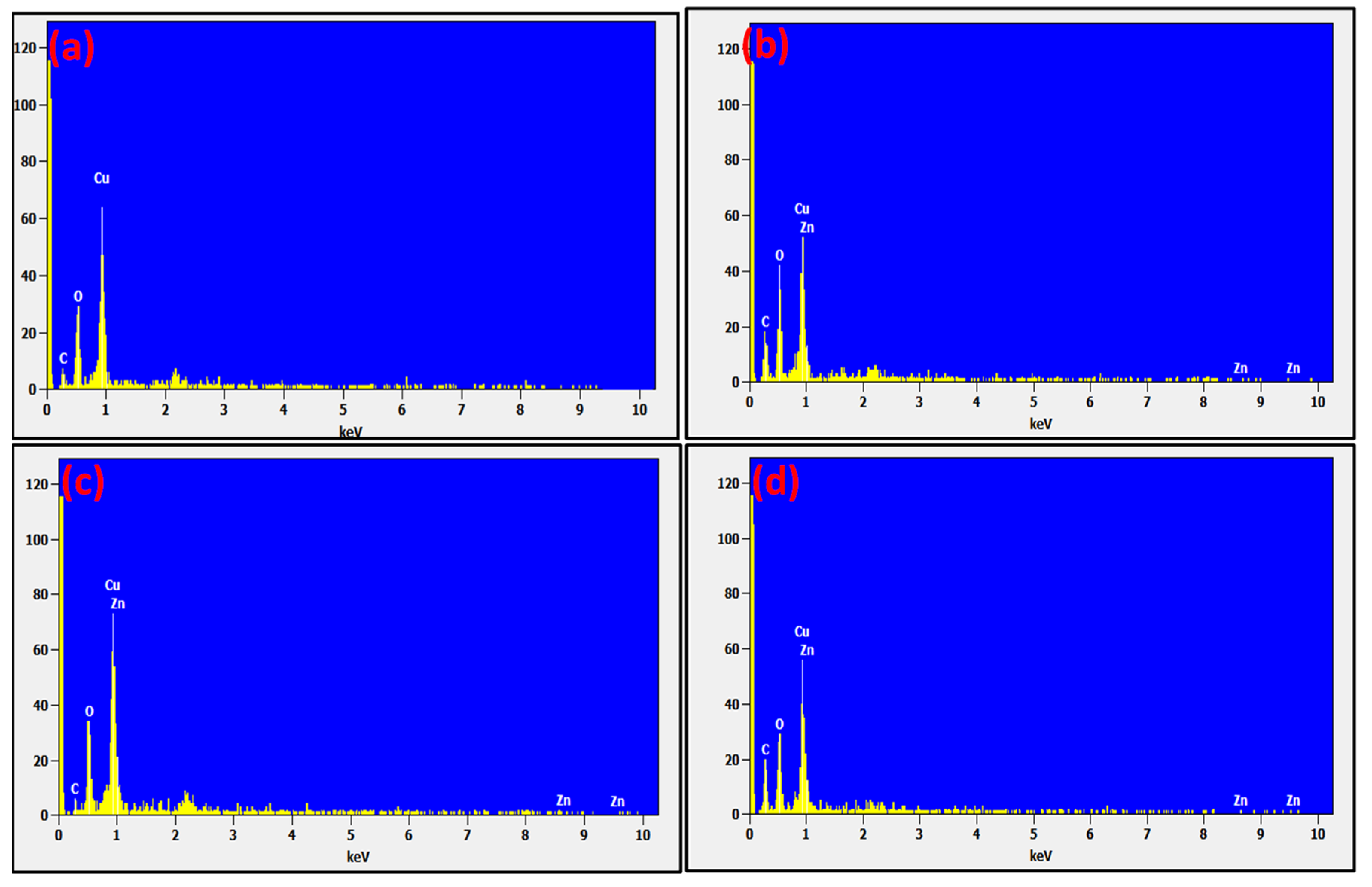
3.2. Morphological and EDAX Analyses
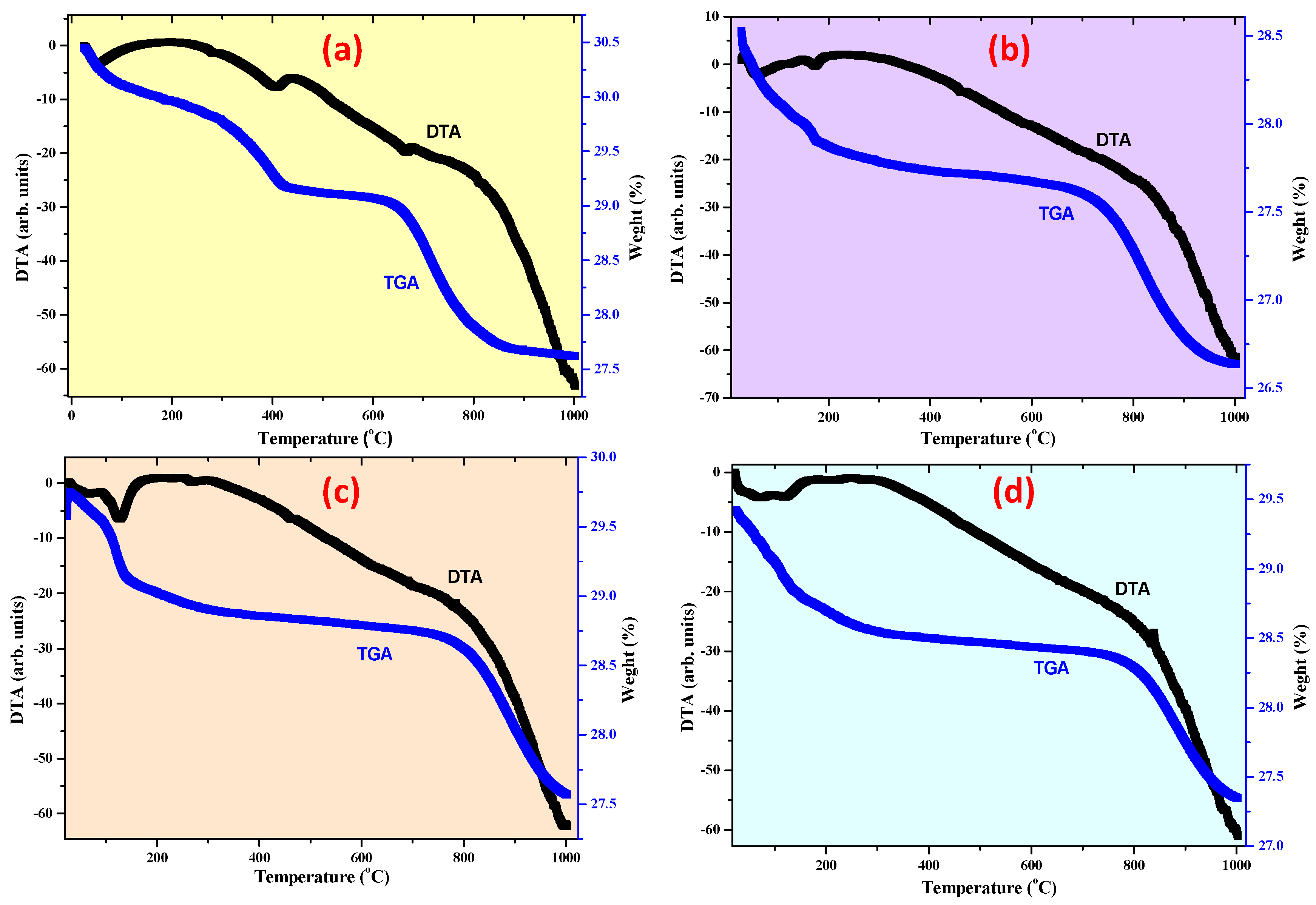
3.2.1. Thermogravimetric Analysis (TGA) and Differential Thermal Analysis (DTA) Analysis
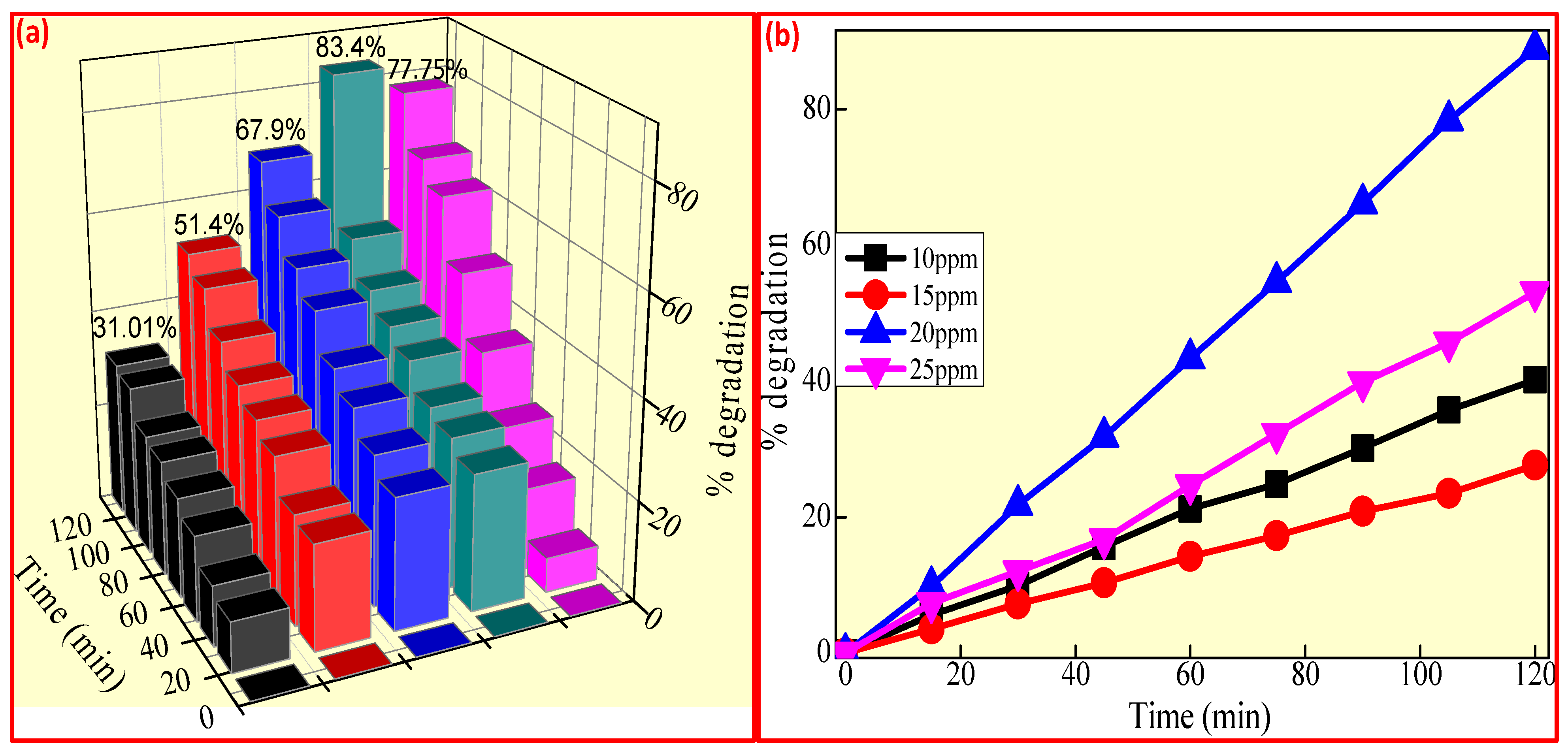
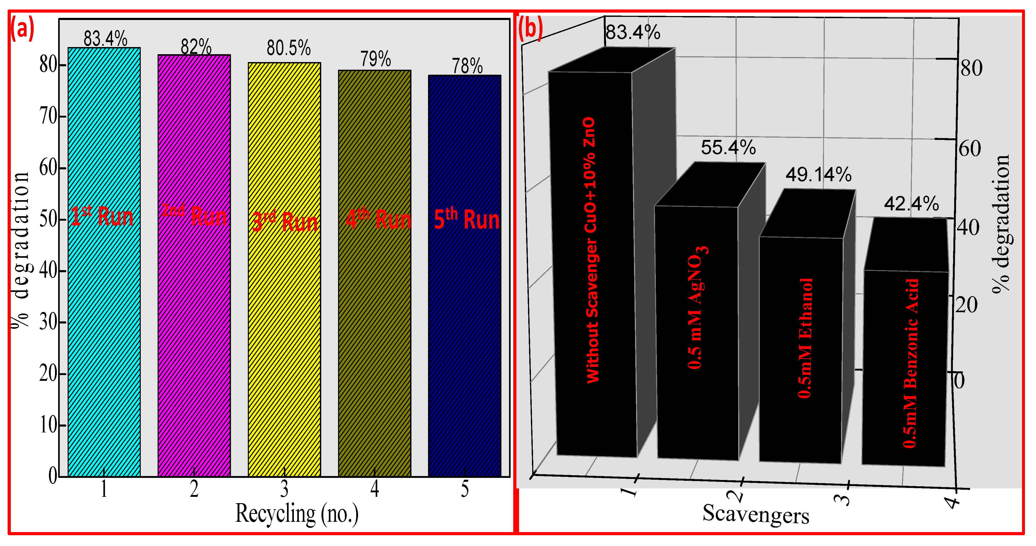
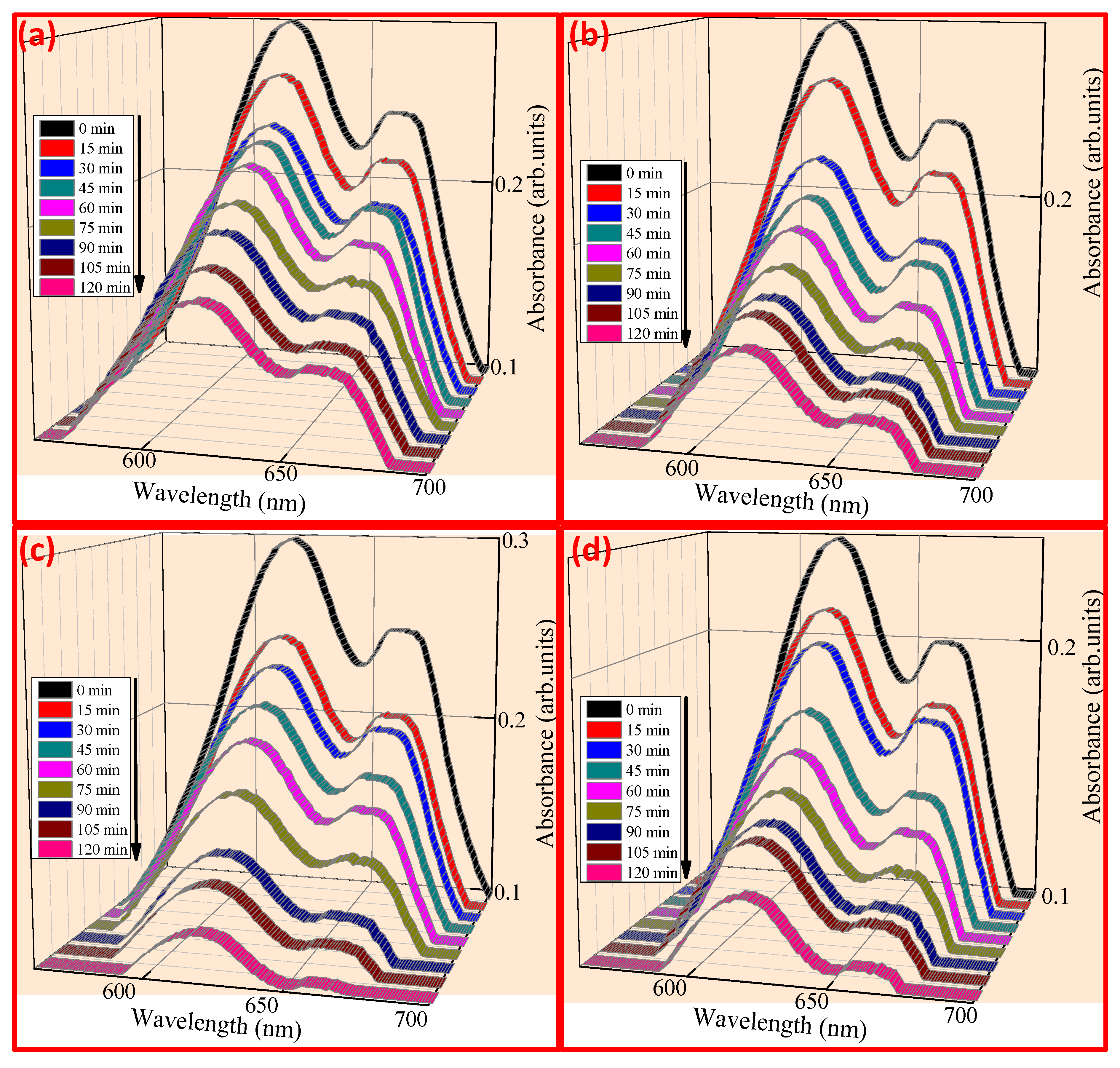
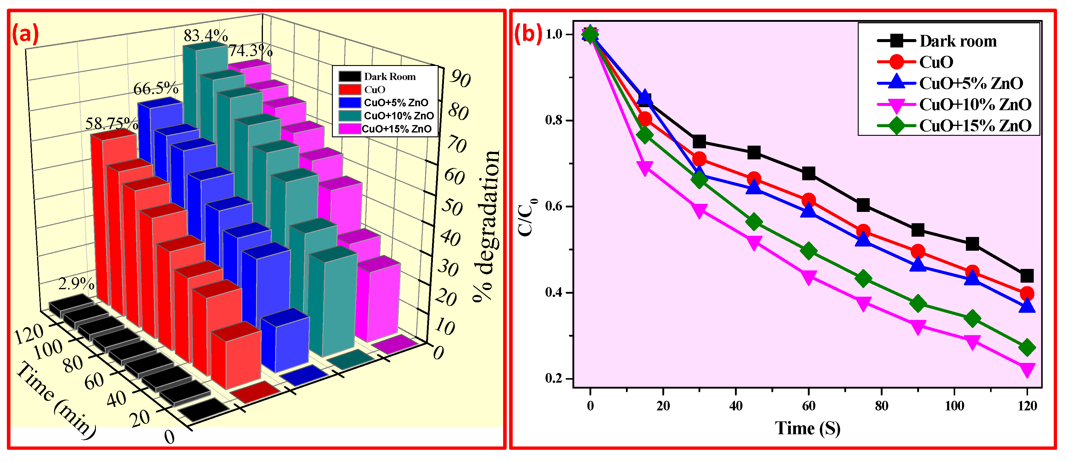
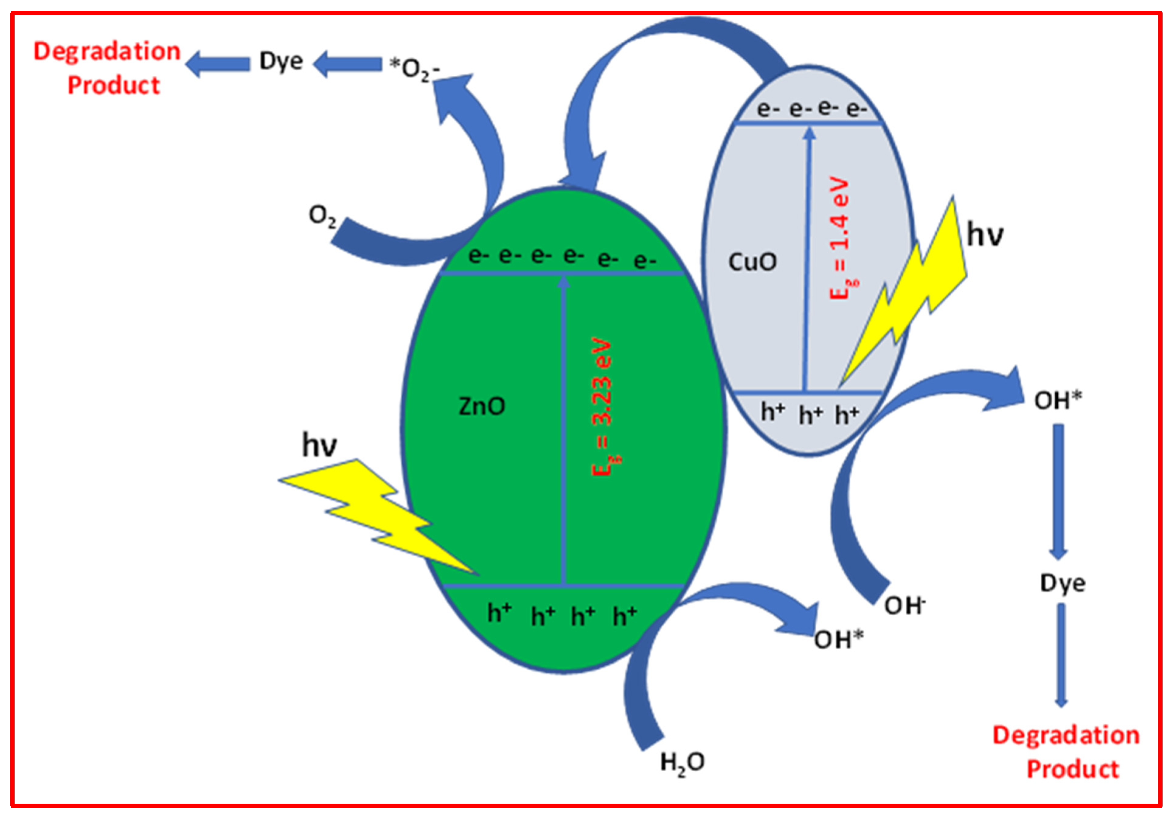
3.2.2. Photocatalytic Studies
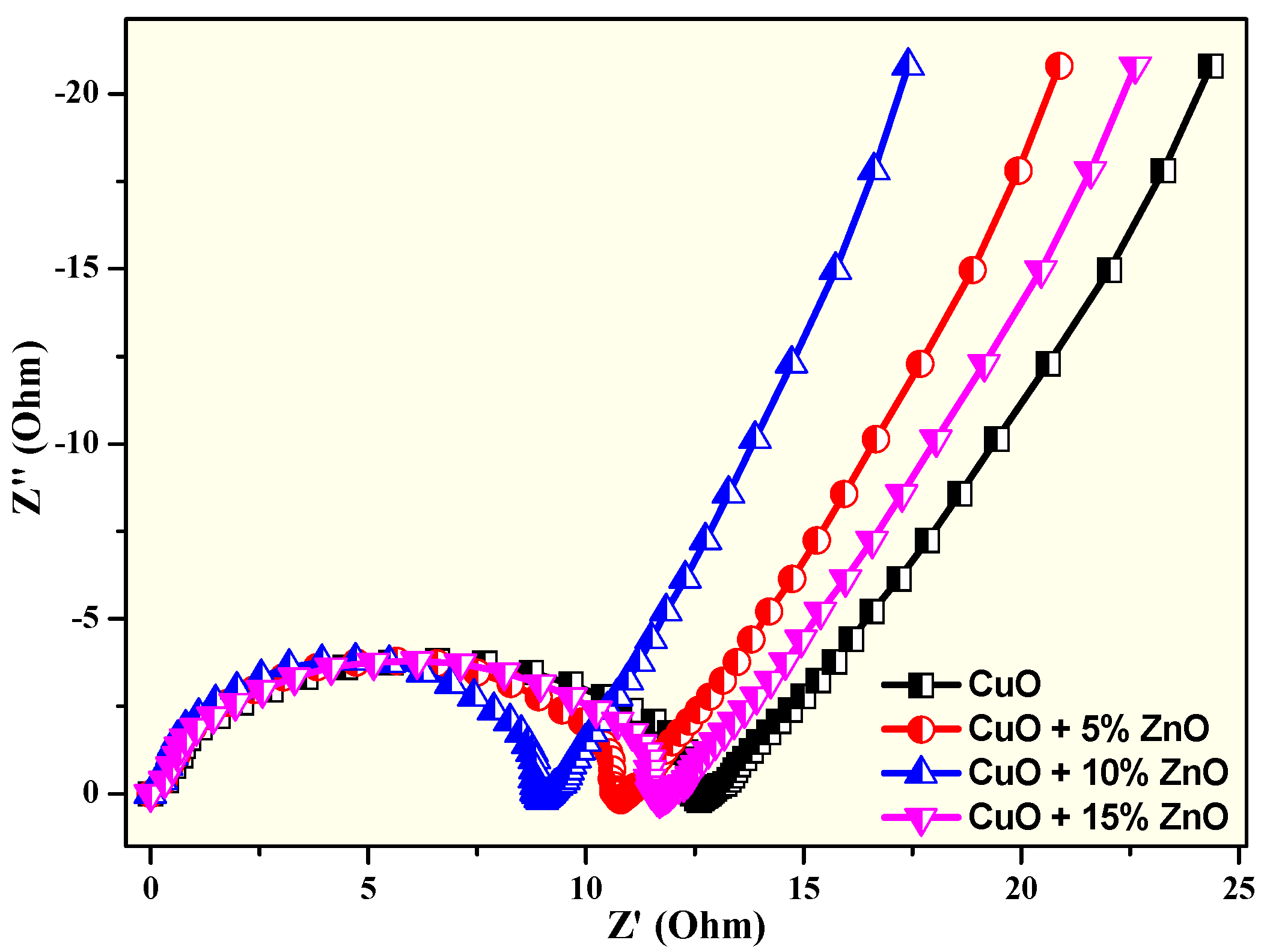
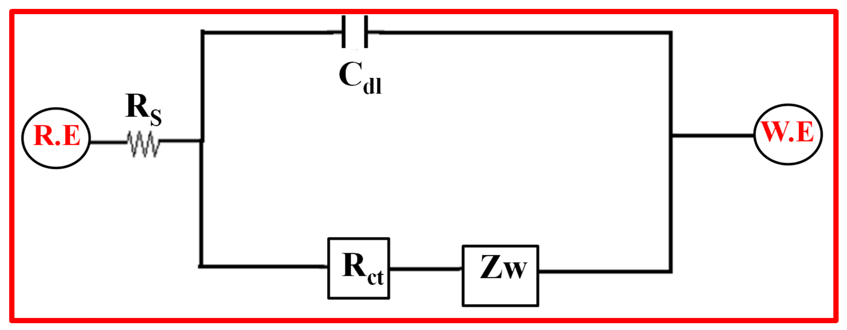
3.2.3. Impedance Spectroscopy Analysis
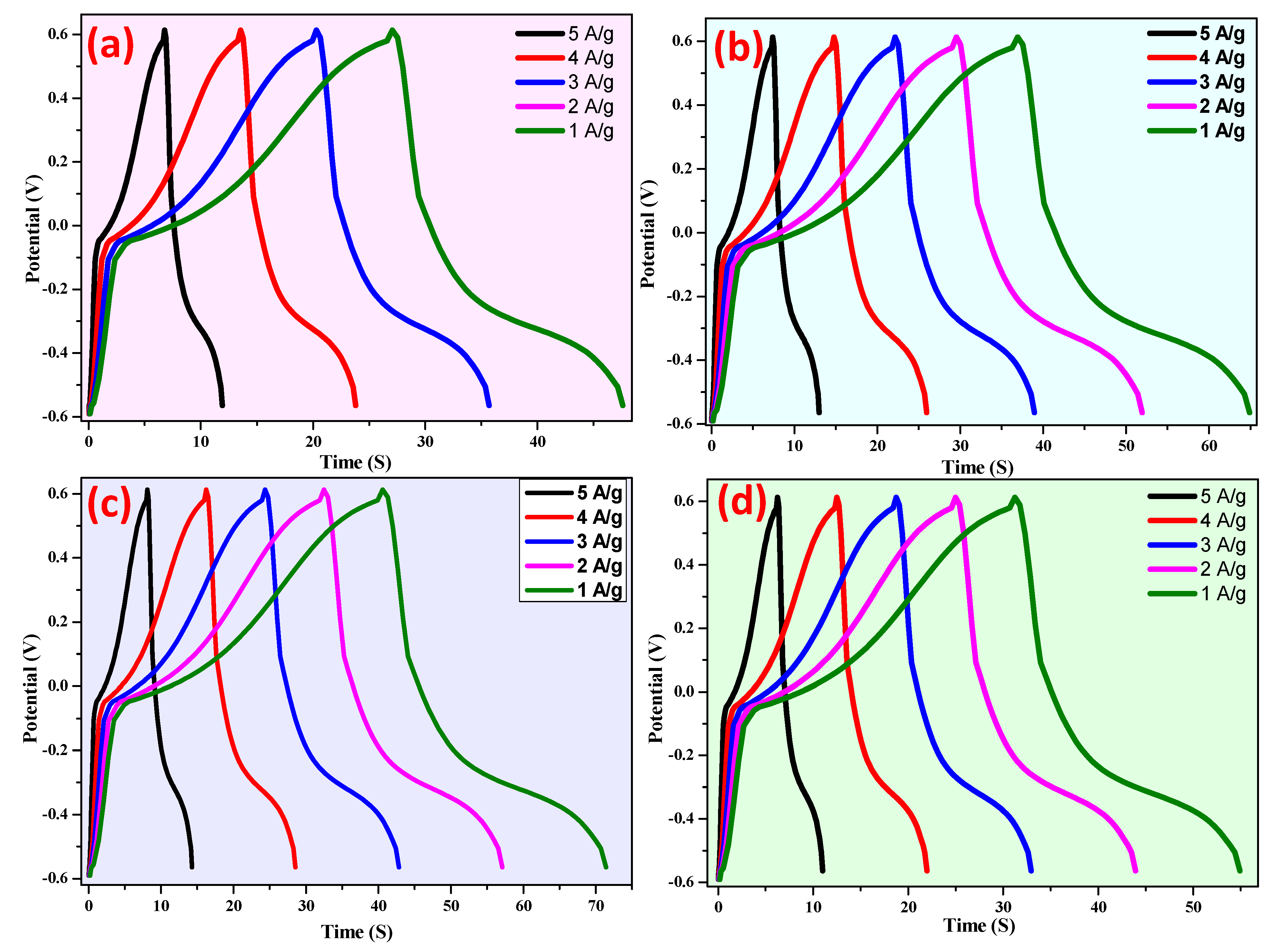
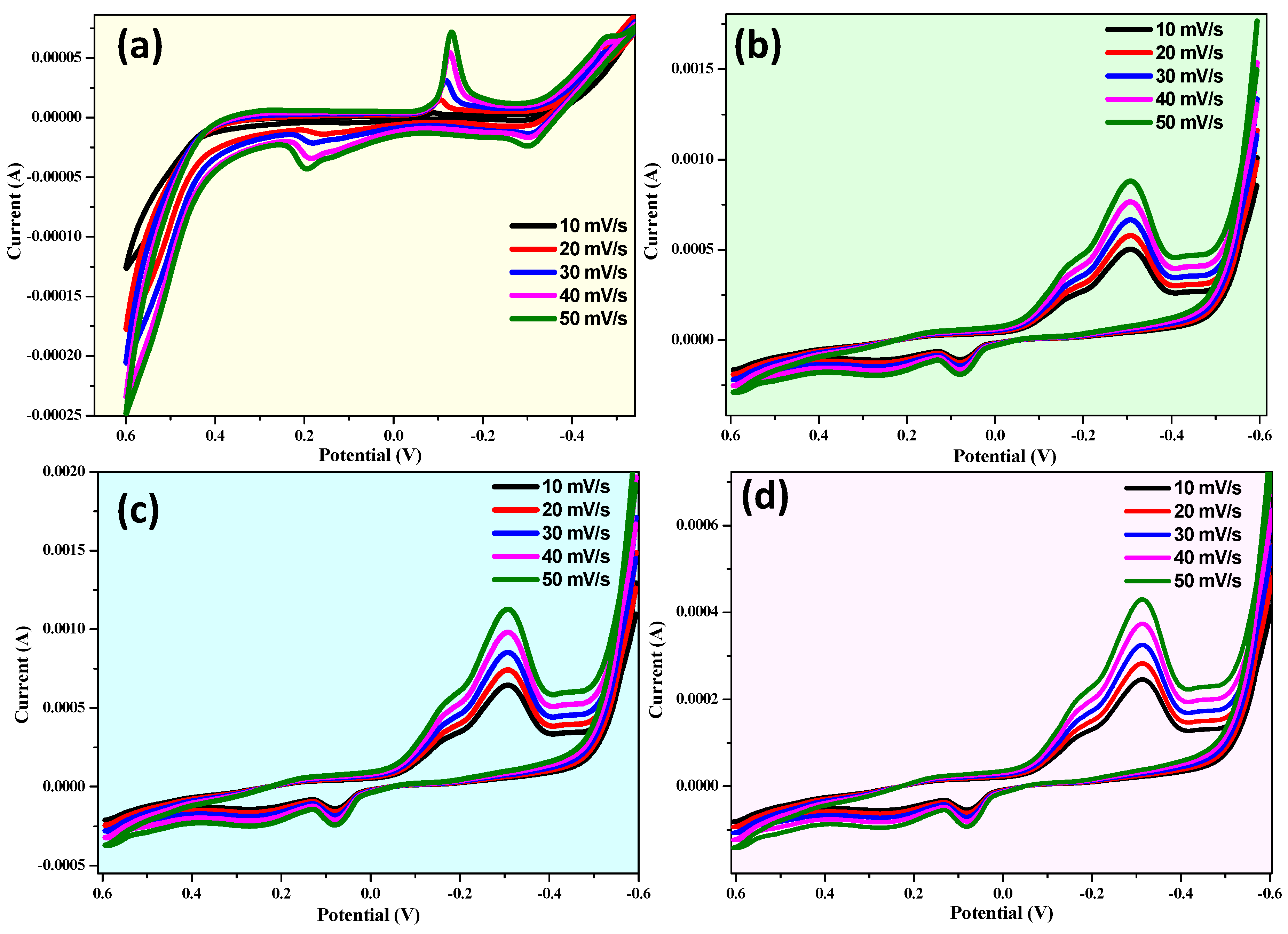
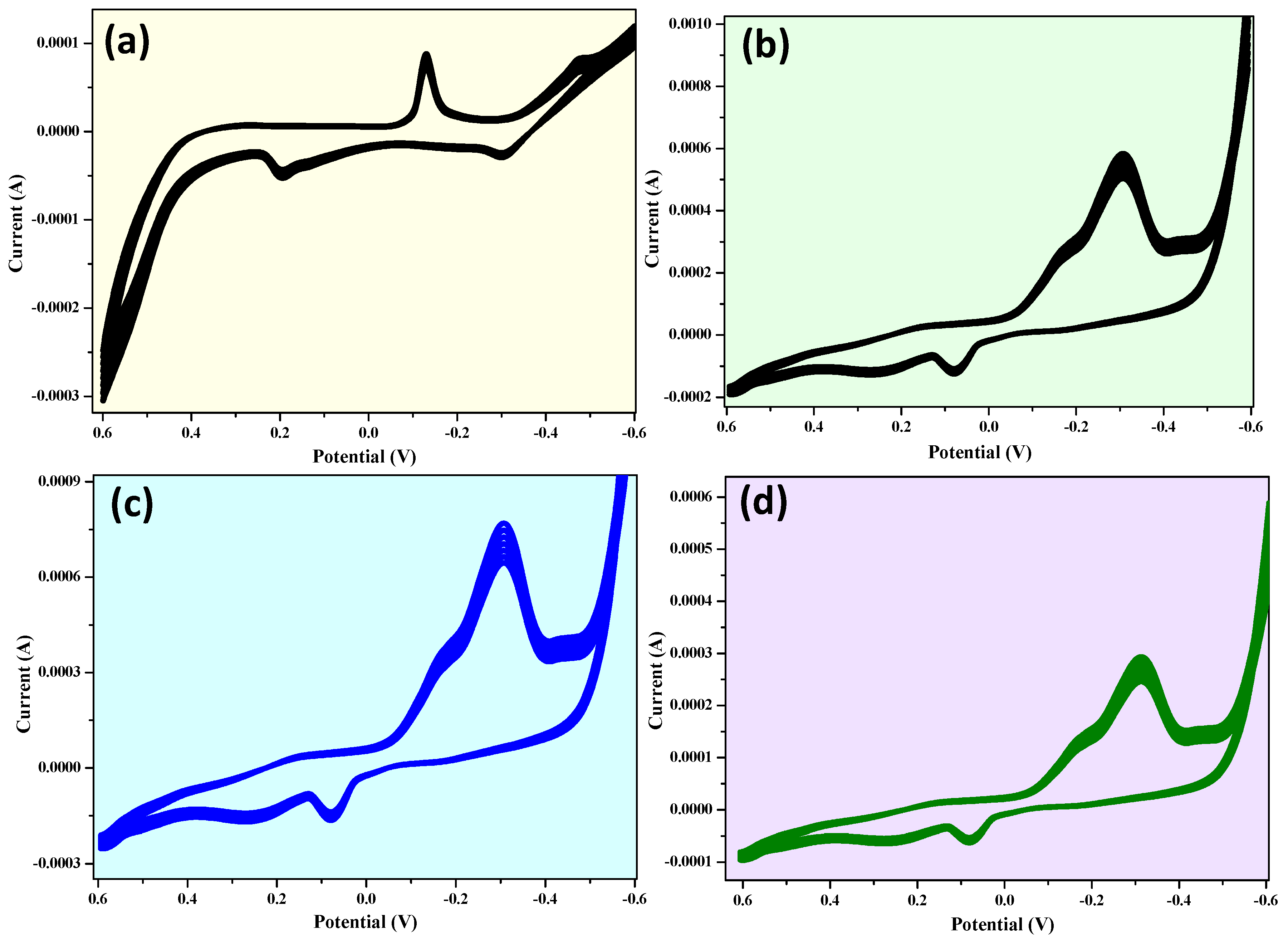
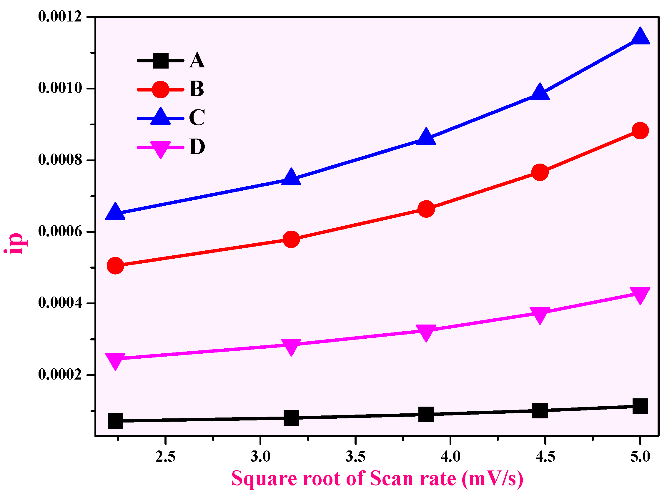
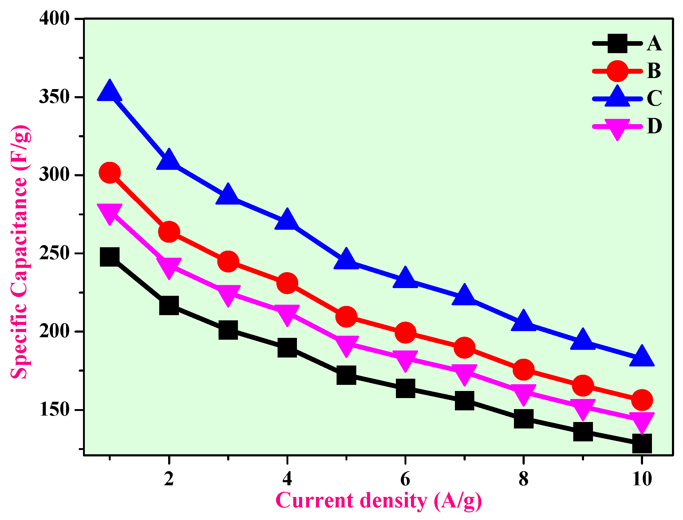
3.3. Charge–Discharge Studies
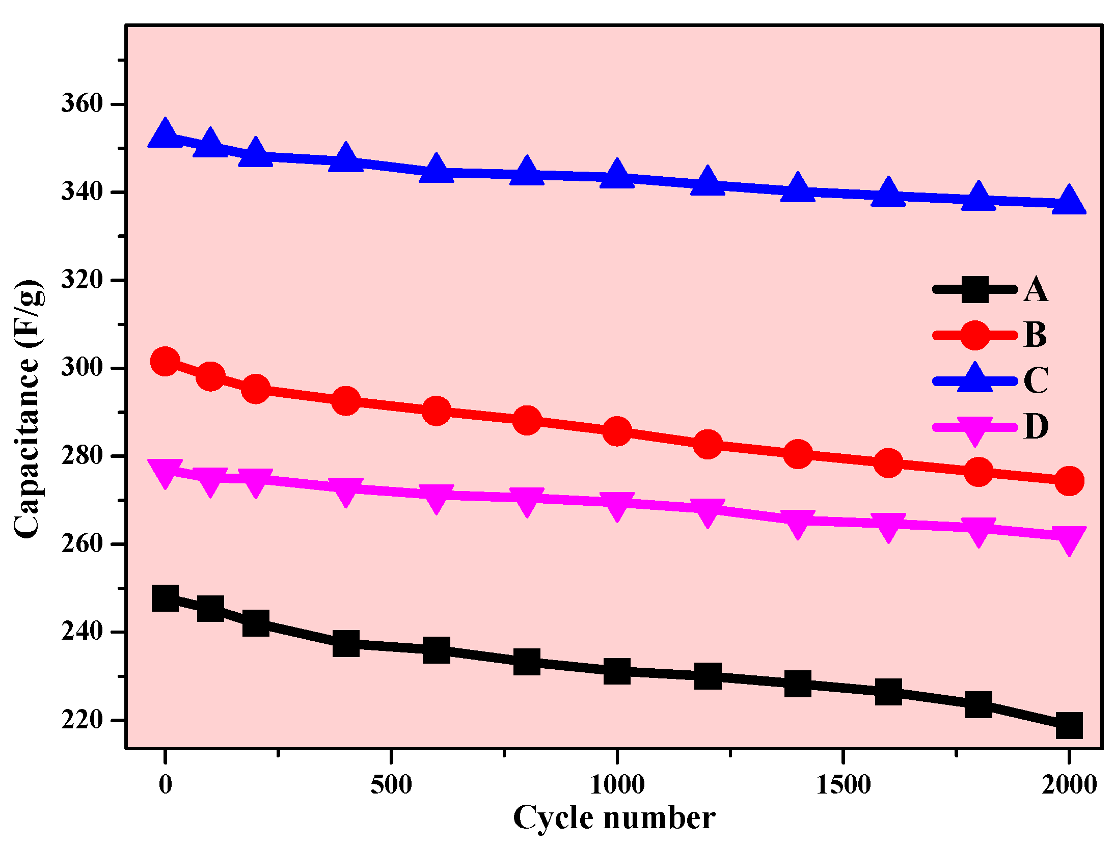
3.4. Cyclic Stability
4. Conclusions
Author Contributions
Funding
Institutional Review Board Statement
Informed Consent Statement
Data Availability Statement
Conflicts of Interest
References
- Conway, B.E. Electrochemical Supercapacitors: Scientific Fundamentals and Technological Applications; Springer: Berlin/Heidelberg, Germany, 1999. [Google Scholar]
- Burke, A. Ultracapacitors: Why, how, and where is the technology. J. Power Sources 2000, 91, 37–50. [Google Scholar] [CrossRef]
- Zhang, L.L.; Zhao, X.S. Carbon-based materials as supercapacitor electrodes. Chem. Soc. Rev. 2009, 38, 2520–2531. [Google Scholar] [CrossRef] [PubMed]
- Winter, M.; Brodd, R.J. What are batteries, fuel cells, and supercapacitors. Chem. Rev. 2004, 104, 4245–4269. [Google Scholar] [CrossRef] [PubMed]
- Miller, J.R.; Simon, P. Electrochemical capacitors for energy management. Science 2008, 321, 651–652. [Google Scholar] [CrossRef]
- Alam, M.W.; Al Qahtani, H.S.; Souayeh, B.; Ahmed, W.; Albalawi, H.; Farhan, M.; Abuzir, A.; Naeem, S. Novel copper-zinc-manganese ternary metal oxide nanocomposite as heterogeneous catalyst for glucose sensor and antibacterial activity. Antioxidants 2022, 11, 1064. [Google Scholar] [CrossRef]
- Cai, J.; Niu, H.; Li, Z.; Du, Y.; Cizek, P.; Xie, Z.; Xiong, H.; Lin, T. High-performance supercapacitor electrode materials from cellulose-derived carbon nanofibers. ACS Appl. Mater. Interfaces 2015, 7, 14946–14953. [Google Scholar] [CrossRef]
- Nie, Y.F.; Wang, Q.; Chen, X.Y.; Zhang, Z.J. Synergistic effect of novel redox additives of p-nitroaniline and dimethylglyoxime for highly improving the supercapacitor performances. Phys. Chem. Chem. Phys. 2016, 18, 2718–2729. [Google Scholar] [CrossRef]
- Lam, L.T.; Louey, R. Development of ultra-battery for hybrid-electric vehicle applications. J. Power Sources 2006, 158, 1140–1148. [Google Scholar] [CrossRef]
- Stoller, M.D.; Park, S.; Zhu, Y.; An, J.; Ruoff, R.S. Graphene-based ultracapacitors. Nano Lett. 2008, 8, 3498–3502. [Google Scholar] [CrossRef]
- Xu, G.; Zheng, C.; Zhang, Q.; Huang, J.; Zhao, M.; Nie, J.; Wang, X.; Wei, F. Binder-freeactivated carbon/carbon nanotube paper electrodes for use in supercapacitors. Nano Res. 2011, 4, 870–881. [Google Scholar] [CrossRef]
- Zheng, C.; Zhou, X.; Cao, H.; Wang, G.; Liu, Z. Synthesisofporousgraphene/activatedCarbon composite with high packing density and large specific surface area for supercapacitor electrode material. J. Power Sources 2014, 258, 290–296. [Google Scholar] [CrossRef]
- JSieben, J.; Morallón, E.; Cazorla-Amorós, D. Flexible ruthenium oxide-activated carbon cloth composites prepared by simple Electrodeposition methods. Energy 2013, 58, 519–526. [Google Scholar] [CrossRef]
- Alam, M.W.; Azam, H.; Khalid, N.R.; Naeem, S.; Hussain, M.K.; BaQais, A.; Farhan, M.; Souayeh, B.; Zaidi, N.; Khan, K. Enhanced photocatalytic performance of Ag3PO4/Mn-ZnO nanocomposite for the degradation of Tetracycline Hydrochloride. Crystals 2022, 12, 1156. [Google Scholar] [CrossRef]
- Lota, K.; Sierczynska, A.; Lota, G. Supercapacitors based on nickel oxide/carbon materials composites. Int. J. Electrochem. 2011, 2011, 321473. [Google Scholar] [CrossRef]
- Hu, C.; He, S.; Jiang, S.; Chen, S.; Hou, H. Natural source derived carbon paper supported conducting polymer nanowire arrays for high performance supercapacitors. RSC Adv. 2015, 5, 14441–14447. [Google Scholar] [CrossRef]
- Shi, Y.; Pan, L.; Liu, B.; Wang, Y.; Cui, Y.; Bao, Z.; Yu, G. Nanostructured conductive polypyrrole hydrogels as high-performance flexible supercapacitor electrodes. J. Mater. Chem. A 2014, 2, 6086–6091. [Google Scholar] [CrossRef]
- Cozzoli, P.D.; Kornowski, A.; Weller, H. Low-temperature synthesis of soluble and processable organic-capped anatase TiO2nanorods. J. Am. Chem. Soc. 2003, 125, 14539–14548. [Google Scholar] [CrossRef] [PubMed]
- Hu, C.C.; Chang, K.H.; Lin, M.C.; Wu, Y.T. Design and tailoring of the nanotubular arrayed architecture of hydrous RuO2 for next generation supercapacitors. Nano Lett. 2006, 6, 2690–2695. [Google Scholar] [CrossRef]
- Sahay, R.; Kumar, P.S.; Aravindan, V.; Sundaramurthy, J.; Ling, W.C.; Mhaisalkar, S.G.; Ramakrishna, S.; Madhavi, S. High aspect ratio electro spun CuO nano fibers as anode material for lithium-ion batteries with superior cycle ability. J. Phys. Chem. C 2012, 116, 18087–18092. [Google Scholar] [CrossRef]
- Waqas Alam, M.; Khatoon, U.; Qurashi, A. Synthesis and characterization of Cu-SnO2 nanoparticles deposited on glass using ultrasonic spray pyrolysis and their H2S sensing properties. Curr. Nanosci. 2012, 8, 919–924. [Google Scholar] [CrossRef]
- Liang, C.; Gao, M.; Pan, H.; Liu, Y.; Yan, M. Lithium alloys and metal oxides ashigh-capacity anode materials for lithium-ion batteries. J. Alloys Compd. 2013, 575, 246–256. [Google Scholar] [CrossRef]
- Shaikh, J.S.; Pawar, R.C.; Moholkar, A.V.; Kim, J.H.; Patil, P.S. CuO-PAA hybrid films: Chemical synthesis and supercapacitor behaviour. Appl. Surf. Sci. 2011, 257, 4389–4397. [Google Scholar] [CrossRef]
- Chandekar, K.V.; Shkir, M.; Al-Shehri, B.M.; Al Faifyb, S.; Halor, R.G.; Khane, A.; Al-Namshah, K.S.; Hamdy, M.S. Visible light sensitive Cu doped ZnO: Facile synthesis, characterization and high photocatalytic response. Mater. Charact. 2020, 165, 110387. [Google Scholar] [CrossRef]
- Zhang, T.; Tang, X.; Zhang, J.; Zhou, T.; Wang, H.; Wu, C.; Xia, X.; Xie, C.; Zeng, D. Preparation, characterization and photocatalytic performance of heterostructured CuO–ZnO-loaded composite nanofiber membranes. Langmuir 2018, 34, 14577–14585. [Google Scholar] [CrossRef] [PubMed]
- Sivasankar, K.; Rani, K.K.; Wang, S.-F.; Devasenathipathy, R.; Lin, C.-H. Copper Nanoparticle and Nitrogen Doped Graphite Oxide Based Biosensor for the Sensitive Determination of Glucose. Nanomaterials 2018, 8, 429. [Google Scholar] [CrossRef] [PubMed]
- Chen, J.T.; Zhang, F.; Wang, J.; Zhang, G.A.; Miao, B.B.; Fan, X.Y.; Yan, D.; Yan, P.X. CuO nanowires synthesized by thermal oxidation route. J. Alloys Compd. 2008, 454, 268. [Google Scholar] [CrossRef]
- Dierstein, A.; Natter, H.; Meyer, F.; Stephan, H.O.; Kropf, C.; Hempelmann, R. Electrochemical deposition under oxidizing conditions (EDOC): A new synthesis for nanocrystalline metal oxides. Scr. Mater. 2001, 44, 2209. [Google Scholar] [CrossRef]
- Yu, L.; Zhang, G.; Wu, Y.; Bai, X.; Guo, D. Cupric oxide nanoflowers synthesized with a simple solution route and their field emission. J. Cryst. Growth 2008, 310, 3125. [Google Scholar] [CrossRef]
- Zhu, J.; Bi, H.; Wang, Y.; Wang, X.; Yang, X.; Lu, L. Synthesis of flower-like CuO nanostructures via a simple hydrolysis route. Mater. Lett. 2007, 61, 5236. [Google Scholar] [CrossRef]
- Su, Y.K.; Shen, C.M.; Yang, H.T.; Li, H.L.; Gao, H.J. Controlled synthesis of highly ordered CuO nanowire arrays by template-based sol-gel route. Trans. Nonferrous Met. Soc. China 2007, 17, 783. [Google Scholar] [CrossRef]
- Han, D.; Yang, H.; Zhu, C.; Wang, F. Controlled synthesis of CuO nanoparticles using TritonX-100-based water-in-oil reverse micel. Powder Technol. 2008, 185, 286. [Google Scholar] [CrossRef]
- Tang, X.L.; Ren, L.; Sun, L.N.; Tian, W.G.; Cao, M.H.; Hu, C.W. A solvothermal route to Cu2O nanocubes and Cu nanoparticles. Chem. Res. Chin. Univ. 2006, 22, 551. [Google Scholar] [CrossRef]
- Song, X.; Yu, H.; Sun, S.L. Single-crystalline CuO nanobelts fabricated by a convenient route. J. Colloid Interface Sci. 2005, 289, 591. [Google Scholar] [CrossRef] [PubMed]
- Keyson, D.; Volanti, D.P.; Cavalcante, L.S.; Simes, A.Z.; Varela, J.A.; Longo, E. CuO urchin-nanostructures synthesized from a domestic hydrothermal microwave method. Mater. Res. Bull. 2008, 43, 775. [Google Scholar] [CrossRef]
- Xu, X.; Zhang, M.; Feng, J.; Zhang, M. Shape-controlled synthesis of single-crystalline cupric oxide by microwave heating using an ionic liquid. Mater. Lett. 2008, 62, 2790. [Google Scholar] [CrossRef]
- Melghit, K.; Wen, L.S. The effect of starting materials on the morphology and particle size of copper pyrovanadate Cu3V2O7(OH)2·2H2O. Ceram. Int. 2005, 31, 223. [Google Scholar] [CrossRef]
- Almasian, A.; Mahmoodi, N.M.; Olya, M.E. Tectomer grafted nanofiber: Synthesis, characterization and dye removal ability from multicomponent system. J. Ind. Eng. Chem. 2015, 32, 85–98. [Google Scholar] [CrossRef]
- Mahmoodi, N.M.; Ghezelbash, M.; Shabanian, M.; Aryanasab, F.; Saeb, M.R. Efficient removal of cationic dyes from colored wastewaters by dithiocarbamate-functionalized graphene oxide nanosheets: From synthesis to detailed kinetics studies. J. Taiwan Inst. Chem. Eng. 2017, 81, 239–246. [Google Scholar] [CrossRef]
- Hosseini, F.; Sadighian, S.; Hosseini-Monfared, H.; Mahmoodi, N.M. Dye removal and kinetics of adsorption by magnetic chitosan nanoparticles. Desalination Water Treat. 2016, 57, 24378–24386. [Google Scholar] [CrossRef]
- Shilpa Amulya, M.A.; Nagaswarupa, H.P.; Anil Kumar, M.R.; Ravikumar, C.R.; Kusuma, K.B. Sonochemical synthesis of MnFe2O4 nanoparticles and their electrochemical and photocatalytic properties. J. Phys. Chem. Solids 2021, 148, 109661. [Google Scholar] [CrossRef]
- Siddiqui, V.U.; Ansari, A.; Taazeem Ansari, M.; Akram, M.K.; Siddiqi, W.A.; Alosaimi, A.M.; Hussein, M.A.; Rafatullah, M. Optimization of Facile Synthesized ZnO/CuO Nanophotocatalyst for Organic Dye Degradation by Visible Light Irradiation Using Response Surface Methodology. Catalysts 2021, 11, 1509. [Google Scholar] [CrossRef]
- Abebe, B.; Tsegaye, D.; Sori, C.; Prasad, R.C.K.R.; Murthy, H.C.A. Cu/CuO-Doped ZnO Nanocomposites via Solution Combustion Synthesis for Catalytic 4-Nitrophenol Reduction. ACS Omega 2023, 8, 9597–9606. [Google Scholar] [CrossRef] [PubMed]
- Wu, F.; Wang, X.; Hu, S.; Hao, C.; Gao, H.; Zhou, S. Solid-state preparation of CuO/ZnO nanocomposites for functional supercapacitor electrodes and photocatalysts with enhanced photocatalytic properties. Int. J. Hydrog. Energy 2017, 42, 30098–30108. [Google Scholar] [CrossRef]
- Sivakumar, S.; Robinson, Y.; Mala, N.A. Studies on Photocatalytic Performance and Supercapacitor Applications of Undoped and Cu-Doped ZnO Nanoparticles. Appl. Surf. Sci. Adv. 2022, 12, 100344. [Google Scholar] [CrossRef]
- Brahma, S.; Yeh, Y.-W.; Huang, J.-L.; Liu, C.-P. Cu-Doped p- Type ZnO Nanostructures as Unique Acetone Sensor at Room Temperature (∼25 °C). Appl. Surf. Sci. 2021, 564, 150351. [Google Scholar] [CrossRef]
- Nadargi, D.Y.; Tamboli, M.S.; Patil, S.S.; Dateer, R.B.; Mulla, I.S.; Choi, H.; Suryavanshi, S.S. Microwave-Epoxide-Assisted Hydrothermal Synthesis of the CuO/ZnO Heterojunction: A Highly Versatile Route to Develop H2S Gas Sensors. ACS Omega 2020, 5, 8587–8595. [Google Scholar] [CrossRef]
- Alam, M.W.; Aamir, M.; Farhan, M.; Albuhulayqah, M.; Ahmad, M.M.; Ravikumar, C.R.; Dileep Kumar, V.G.; Ananda Murthy, H.C. Green Synthesis of Ni-Cu-Zn Based Nanosized Metal Oxides for Photocatalytic and Sensor Applications. Crystals 2021, 11, 1467. [Google Scholar] [CrossRef]
- Paraguay-Delgado, F.; Hermida-Montero, L.A.; Morales-Mendoza, J.E.; Durán-Barradas, Z.; Mtz-Enriquez, A.I.; Pariona, N. Photocatalytic Properties of Cu-Containing ZnO Nanoparticles and Their Antifungal Activity against Agriculture-Pathogenic Fungus. RSC Adv. 2022, 12, 9898–9908. [Google Scholar] [CrossRef]
- Mahmoud, A.; Echabaane, M.; Omri, K.; Boudon, J.; Saviot, L.; Millot, N.; Chaabane, R.B. Cu-Doped ZnO Nanoparticles for Non- Enzymatic Glucose Sensing. Molecules 2021, 26, 929. [Google Scholar] [CrossRef]
- Mohan, R.; Krishnamoorthy, K.; Kim, S.J. Enhanced photocatalytic activity of Cu-doped ZnO nanorods. Solid State Commun. 2012, 152, 375–380. [Google Scholar] [CrossRef]
- Fu, M.; Li, Y.; Lu, P.; Liu, J.; Dong, F. Sol–gel preparation and enhanced photocatalytic performance of Cu-doped ZnO nanoparticles. Appl. Surf. Sci. 2011, 258, 1587–1591. [Google Scholar] [CrossRef]
- Panahi-Kalamuei, M.; Mousavi-Kamazani, M.; Salavati-Niasari, M.; Hosseinpour-Mashkani, S.M. A simple sonochemical approach for synthesis of selenium nanostructures and investigation of its light harvesting application. Ultrason. Sonochem. 2015, 23, 246. [Google Scholar] [CrossRef] [PubMed]
- Mamatha, K.M.; Ravikumar, C.R.; Murthy, H.A.; Kumar, V.D.; Kumar, A.N.; Jahagirdar, A.A. Facile green synthesis of Molybdenum oxide nanoparticles using Centella Asiatica plant: Its photocatalytic and electrochemical lead sensor applications. Sens. Int. 2022, 3, 100153. [Google Scholar] [CrossRef]
- Mousavi-Kamazani, M.; Rahmatolahzadeh, R.; Shobeiri, S.A.; Beshkar, F. Sonochemical synthesis, formation mechanism, and solar cell application of tellurium nanoparticles. Ultrason. Sonochem. 2017, 39, 233. [Google Scholar] [CrossRef]
- Saravanakkumar, D.; Oualid, H.A.; Brahmi, Y.; Ayeshamariam, A.; Karunanaithy, M.; Saleem, A.M.; Kaviyarasu, K.; Sivaranjani, S.; Jayachandran, M. Synthesis and characterization of CuO/ZnO/CNTs thin films on copper substrate and its photocatalytic applications. Open Nano 2019, 4, 100025. [Google Scholar] [CrossRef]
- Yadav, M.S.; Tripathi, S.K. Synthesis and characterization of nanocomposite NiO/activated charcoal electrodes for supercapacitor application. Ionics 2017, 23, 2919–2930. [Google Scholar] [CrossRef]
- Yesuraj, J.; Elumalai, V.; Bhagavathiachari, M.; Samuel, A.S.; Elaiyappillai, E.; Johnson, P.M. A facile sonochemical assisted synthesis of α-MnMoO4/PANI nanocomposite electrode for supercapacitor applications. J. Electroanal. Chem. 2017, 797, 78–88. [Google Scholar] [CrossRef]
- Fanga, J.; Xuan, Y. Investigation of optical absorption and photothermal conversion characteristics of binary CuO/ZnO nanofluids. RSC Adv. 2017, 7, 56023. [Google Scholar] [CrossRef]
- Sahu, S.; Samanta, P.K. Peak Profile Analysis of X-ray Diffraction Pattern of Zinc Oxide Nanostructure. J. Nano Electron. Phys. 2021, 13, 05001. [Google Scholar] [CrossRef]
- Inamdar, A.I.; Kim, Y.S.; Sohn, J.S.; Im, H.; Kim, H.; Kim, D.-Y.; Kalubarme, R.S.; Park, C. Supercapacitive Characteristics of Electrodeposited Polyaniline Thin Films Grown on Indium-doped Tin-oxide Substrates. J. Korean Phys. Soc. 2011, 59, 145–149. [Google Scholar] [CrossRef]
- Cullity, B.D. Elements of X-ray Diffraction; Addison-Wesley: Boston, MA, USA, 1956. [Google Scholar]
- Lee, J.B.; Lee, H.J.; Seo, S.H.; Park, J.S. Characterization of undoped and Cu doped ZnO film for surface acoustic wave applications. Thin Solid Film. 2001, 398, 641–646. [Google Scholar] [CrossRef]
- Sharma, P.K.; Kumar, M.; Pandey, A.C. Green luminescent ZnO: Cu2+ nanoparticles and their applications in white light generation from UV LEDs. J. Nanopart. Res. 2011, 13, 1629–1637. [Google Scholar] [CrossRef]
- Che, C.; Liu, X.; Fang, Q.; Chen, X.; Liu, T.; Zhang, M. Self-assembly synthesis of CuO/ZnO hollow microspheres and their photocatalytic performance under natural sunlight. Vacuum 2020, 174, 109198. [Google Scholar]
- Shilpa Amulya, M.A.; Nagaswarupa, H.P.; Anil Kumar, M.R.; Ravikumar, C.R.; Kusuma, K.B. Enhanced photocatalytic and electrochemical properties of Cu doped NiMnFe2O4 nanoparticles synthesized via probe sonication method. Appl. Surf. Sci. Adv. 2020, 2, 100038. [Google Scholar] [CrossRef]
- Devi, A.B.; Moirangthem, D.S.; Talukdar, N.C.; Devi, M.D.; Singh, N.R.; Luwang, M.N. Novel synthesis and characterization of CuO nanomaterials: Biological applications. Chin. Chem. Lett. 2014, 25, 1615–1619. [Google Scholar] [CrossRef]
- Rudresha, K.; Zahir Hussain, A.; Ravikumar, C.R.; Anil Kumar, M.R.; Nagaswarupa, H.P.; Santosh, M.S.; Ananda Murthy, H.C. Synthesis and Characterization of green CuO using Centella Asiatica plant leaf extract: Electrochemical and Photocatalytic activities. Adv. Mater. Lett. 2020, 11, 121586. [Google Scholar] [CrossRef]
- Kumar, A.N.; Jnaneshwara, D.; Ravikumar, C.; Kumar, M.A.; Murthy, H.A.; Shekhar, T.S.; Jahagirdar, A. La10Si6O27: Tb3+ nanomaterial; Its Photocatalytic and Electrochemical Sensor Activities on Disperse Orange and Fast Blue dyes. Sens. Int. 2020, 2, 100076. [Google Scholar] [CrossRef]
- Abebe, B.; Ravikumar, C.R.; Zereffa, E.A.; Kumar, A.N.; Murthy, H.C.A. Photocatalytic and superior ascorbic acid sensor activities of PVA/Zn-Fe-Mn ternary oxide nanocomposite. Inorg. Chem. Commun. 2021, 123, 108343. [Google Scholar] [CrossRef]
- Avinash, B.; Ravikumar, C.R.; Kumar, M.A.; Santosh, M.S.; Pratapkumar, C.; Nagaswarupa, H.P.; Murthy, H.A.; Deshmukh, V.V.; Bhatt, A.S.; Jahagirdar, A.A.; et al. NiO bio-composite materials: Photocatalytic, electrochemical and supercapacitor applications. Appl. Surf. Sci. Adv. 2021, 3, 100049. [Google Scholar] [CrossRef]
- Basavaraju, N.; Prashantha, S.C.; Nagabhushana, H.; Naveen Kumar, A.; Chandrasekhar, M.; Shashi Shekhar, T.R.; Ravikumar, C.R.; Anil Kumar, M.R.; Surendra, B.S.; Nagaswarupa, H.P. Luminescent and thermal properties of novel orange–red emitting MgNb2O6: Sm3+ phosphors for displays, photo catalytic and sensor applications. SN Appl. Sci. 2021, 3, 100049. [Google Scholar] [CrossRef]
- Ranjitha, R.; Meghana, K.N.; Kumar, V.G.D.; Bhatt, A.S.; Jayanna, B.K.; Ravikumar, C.R.; Santosh, M.S.; Madhyastha, H.; Sakai, K. Rapid photocatalytic degradation of cationic organic dyes using Li-doped Ni/NiO nanocomposites and their electrochemical performance. New J. Chem. 2021, 2, 796. [Google Scholar] [CrossRef]
- Raghavendra, N.; Nagaswarupa, H.P.; Shashi Shekhar, T.R.; Mylarappa, M.; Surendra, B.S.; Prashantha, S.C.; Basavaraju, N.; Ravi Kumar, C.R.; Anil Kumar, M.R. Electrochemical sensor studies and optical analysis of developed clay basedCoFe2O4 ferrite NPs. Sens. Int. 2021, 2, 100083. [Google Scholar] [CrossRef]
- Bhuvan Raj, N.; PavithraGowda, N.T.; Pooja, O.S.; Purushotham, B.; Anil Kumar, M.R.; Sukrutha, S.K.; Ravikumar, C.R.; Nagaswarupa, H.P.; Ananda Murthy, H.C.; Boppana, S.B. Harnessing ZnO nanoparticles for antimicrobial and photocatalytic activities. J. Photochem. Photobiol. 2021, 6, 100021. [Google Scholar]
- Raghavendra, N.; Nagaswarupa, H.P.; Shashi Shekhar, T.R.; Mylarappa, M.; Surendra, B.S.; Prashantha, S.C.; Ravikumar, C.R.; Anil Kumar, M.R.; Basavaraju, N. Development of clay ferrite nanocomposite: Electrochemical, sensors and photocatalytic studies. Appl. Surf. Sci. Adv. 2021, 5, 100103. [Google Scholar] [CrossRef]
- Kusuma, K.B.; Manju, M.; Ravikumar, C.R.; Dileepkumar, V.G.; Kumar, A.N.; Santosh, M.S.; Murthy, H.A.; Gurushantha, K. Probe Sonicated synthesis of Bismuth oxide (Bi2O3) nanoparticles: Photocatalytic application and Electrochemical sensing of Ascorbic acid lead. J. Nanomater. 2022, 2022, 3256611. [Google Scholar] [CrossRef]
- Kumar, V.D.; Balaji, K.; Viswanatha, R.; Ambika, G.; Roopa, R.A.; Basavaraja, B.M.; Chennabasappa, M.; Kumar, C.R.; Chen, Z.; Bui, X.; et al. Visible light photodegradation of 2,4-dichlorophenol using nanostructured NaBiS2: Kinetics, cytotoxicity, antimicrobial and electrochemical studies of the photocatalyst. Chemosphere 2022, 287, 132174. [Google Scholar] [CrossRef]
- Alam, M.W.; Kumar, V.G.D.; Ravikumar, C.R.; Prashantha, S.C.; Murthy, H.C.A.; Kumar, M.R.A. Chromium (III) doped polycrystalline MgAl2O4 nanoparticles for photocatalytic and supercapacitor applications. J. Phys. Chem. Solids 2022, 161, 110491. [Google Scholar] [CrossRef]
- Shashank, M.; Naik, H.B.; Patil, S.B.; Viswantha, R.; Nagaraju, G. Green synthesis of molybdenum oxide nanoparticles: Advanced electrode material for electrochemical lithium storage. Microchem. J. 2021, 171, 106818. [Google Scholar] [CrossRef]
- Kumar, M.A.; Abebe, B.; Nagaswarupa, H.P.; Murthy, H.A.; Ravikumar, C.R.; Sabir, F.K. Enhanced photocatalytic and electrochemical performance of TiO2-Fe2O3 nanocomposite: Its applications in dye decolorization and as supercapacitors. Sci. Rep. Nat. 2020, 10, 1249. [Google Scholar] [CrossRef]
- Masunga, N.; Mmelesi, O.K.; Kefeni, K.K.; Mamba, B.B. Recent advances in copper ferrite nanoparticles and nanocomposites synthesis, magnetic properties and application in water treatment: Review. J. Environ. Chem. Eng. 2019, 7, 103179. [Google Scholar] [CrossRef]
- Bekru, A.G.; Tufa, L.T.; Zelekew, O.A.; Goddati, M.; Lee, J.; Sabir, F.K. Green Synthesis of a CuO-ZnO Nanocomposite for Efficient Photodegradation of Methylene Blue and Reduction of 4-Nitrophenol. ACS Omega 2022, 7, 30908–30919. [Google Scholar] [CrossRef] [PubMed]
- Bhat, A.H.; Chisti, H.T.N. Facile Fabrication of Ternary Metal Oxide ZnO/CuO/SnO2 Nanocomposite for Excellent Photocatalytic degradation of Fast Green Dye. Int. J. Environ. Anal. Chem. 2021, 1–22. [Google Scholar] [CrossRef]
- Alzahrani, E. Chitosan Membrane Embedded with ZnO/CuO Nanocomposite for the Photodegradation of Fast Green Dye Under Artificial and Solar Irradiation. Analyitical Chem. Insights 2018, 13, 1177390118763361. [Google Scholar] [CrossRef]
- Ataabadi, M.R.; Jamshidi, M. Silane modification of TiO2 nanoparticles and usage in acrylic film for effective photocatalytic degradation of methylene blue under visible light. Sci. Rep. 2023, 13, 7383. [Google Scholar] [CrossRef] [PubMed]
- Manjula, S.N.; Chandrasekhar, M.; Naik, R.; Revathi, V.; Nagabhushana, H.; Ravikumar, C.R.; Surendra, B.S.; Kumar, A.N. Low temperature synthesized MgAl2O4:Eu3+ nanophosphors and its structural validations using DFT: Photoluminescent, Photocatalytic and Electrochemical properties of multifunctional applications. Lumin. J. Biol. Chem. Lumin. 2022, 38, 1149–1166. [Google Scholar]
- Naik, R.; Kumar, A.N.; Shanbhag, V.; Ravikumar, C.R.; Revathi, V.; Basavaraju, N.; Prashantha, S.C.; Girish, K.M.; Nagabhushana, H. Aloe barbadensis Mill leaf gel assisted combustion synthesized ZnO:Ni3+ Electrochemical sensor for ascorbic acid detection and photocatalysis. Inorg. Chem. Commun. 2022, 143, 100153. [Google Scholar] [CrossRef]
- Shruthi, B.; Madhu, B.J.; Bheema Raju, V. Influence of TiO2 on the electrochemical performance of pasted type β-nickel hydroxide electrode in alkaline electrolyte. J. Energy Chem. 2016, 25, 41–48. [Google Scholar] [CrossRef]
- Dhananjaya, N.; Ambujakshi, N.P.; Ravikumar, C.R.; Naveen Kumar, A. Comparative study on photocatalytic degradation and sensor properties of Chonemorpha fragrans leaf extract assisted MgxZn1−xO(0 ≤ x ≤ 1) nanoparticles. Inorg. Chem. Commun. 2022, 144, 109827. [Google Scholar] [CrossRef]
- Rudresha, K.; Zahir Hussain, A.; Ravikumar, C.R.; Anil Kumar, M.R.; Naveen Kumar, A.; Manjunatha, A.S.; Nagaswarupa, H.P.; Shilpa Amulya, M.A.; Ananda Murthy, H.C. UV light Assisted De-colorization of Dyes and electrochemical Sensing of Arsenic by CuO–ZnO Hybrid Nanocomposite synthesized via sonication method. J. Phys. Chem. Solids 2022, 144, 109827. [Google Scholar]
- Kong, L.; Yan, Q.; Wang, Y.; Wang, Q.; Andrews, C.B.; Zheng, C. Self-supported trimetallic NiZnLa nanosheets on hierarchical porous graphene oxide-polymer composite fibers for enhanced phosphate removal from water. J. Colloid Interface Sci. 2022, 628, 807–818. [Google Scholar] [CrossRef]
- Martin, P. Andersson Entropy reduction from strong localization an explanation for enhanced reaction rates of organic synthesis in aqueous micelles. J. Colloid Interface Sci. 2022, 628, 819–828. [Google Scholar]
- Tayyab, M.; Liu, Y.; Liu, Z.; Xu, Z.; Yue, W.; Zhou, L.; Lei, J.; Zhang, J. A new breakthrough in photocatalytic hydrogen evolution by amorphous and chalcogenide enriched cocatalysts. Chem. Eng. J. 2023, 455, 140601. [Google Scholar] [CrossRef]
- Shruthi, B.; Madhu, B.J.; Bheema Raju, V.; Vynatheya, S.; Veena Devi, B.; Jayashree, G.V.; Ravikumar, C.R. Synthesis, spectroscopic analysis and electrochemical performance of modified bnickel hydroxide electrode with CuO. J. Sci. Adv. Mater. Devices 2016, 2, 93–98. [Google Scholar] [CrossRef]
- Avinash, B.; Ravikumar, C.R.; Kumar, M.A.; Nagaswarupa, H.P.; Santosh, M.S.; Bhatt, A.S.; Kuznetsov, D. Nano CuO: Electrochemical sensor for the determination of paracetamol and D-glucose. J. Phys. Chem. Solids 2019, 134, 193–200. [Google Scholar] [CrossRef]
- Ravikumar, C.R.; Kotteeswaran, P.; Bheema raju, V.; Murugan, A.; Santosh, M.S.; Nagaswarupa, H.P.; Prashantha, S.C.; Anil Kumar, M.R.; Shivakumar, M.S. Influence of zinc additive and pH on the electrochemical activities of β-nickel hydroxide materials and its applications in secondary batteries. J. Energy Storage 2017, 9, 12–24. [Google Scholar] [CrossRef]
- Rashmi, B.N.; Harlapur, S.F.; Gurushantha, K.; Ravikumar, C.R.; Kumar, M.A.; Santosh, M.S.; Kumar, V.D.; Kumar, A.N.; Azad, A.K.; Murthy, H.A. Facile green synthesis of lanthanum oxide nanoparticles using Centella Asiatica and Tridax plants: Photocatalytic, electrochemical sensor and antimicrobial studies. Appl. Surf. Sci. Adv. 2022, 7, 100210. [Google Scholar] [CrossRef]
- Nagarani, S.; Sasikala, G.; Yuvaraj, M.; Kumar, R.D.; Balachandran, S.; Kumar, M. ZnO-CuO Nanoparticles Enameled on Reduced Graphene Nanosheets as Electrode Materials for Supercapacitors. J. Energy Storage 2022, 52, 104969. [Google Scholar] [CrossRef]
- Kumar, R.; Singh, B.K.; Soam, A.; Parida, S.; Sahajwalla, V.; Bhargava, P. In situ carbon-supported titanium dioxide (ICS-TiO 2) as an electrode material for high performance supercapacitors. Nanoscale Adv. 2020, 2, 2376–2386. [Google Scholar] [CrossRef]
- Li, Z.; Zhou, Z.; Yun, G.; Shi, K.; Lv, X.; Yang, B. High-performance Solid-state Supercapacitors Based on Graphene-ZnO Hybrid Nanocomposites. Nanoscale Res. Lett. 2013, 8, 473. [Google Scholar] [CrossRef]


| Sl. No | Synthesis Method | Work Done | Reference |
|---|---|---|---|
| 1 | Solution combustion | Photoluminescence and catalytic 4-nitrophenol reduction | [43] |
| 2 | Solid-state preparation of CuO/ZnO Nanocomposites | Functional supercapacitor electrodes and photocatalysts | [44] |
| 3 | co-precipitation method | Photocatalytic and supercapacitors | [45] |
| 4 | Chemical vapor deposition | Acetone sensor | [46] |
| 5 | Hydrothermal synthesis | H2S gas sensor | [47] |
| 6 | Green synthesis | Photocatalytic and Sensor Applications | [48] |
| 7 | Hydrothermal method | Photo discoloration of methyl orange dye and antifungal study | [49] |
| 8 | Sol-gel process | Glucose sensing | [50] |
| 9 | Vapor transport method | Photo discoloration of resazurin (Rz) dye | [51] |
| 10 | Sol-gel method | Photo discoloration of methyl orange dye | [52] |
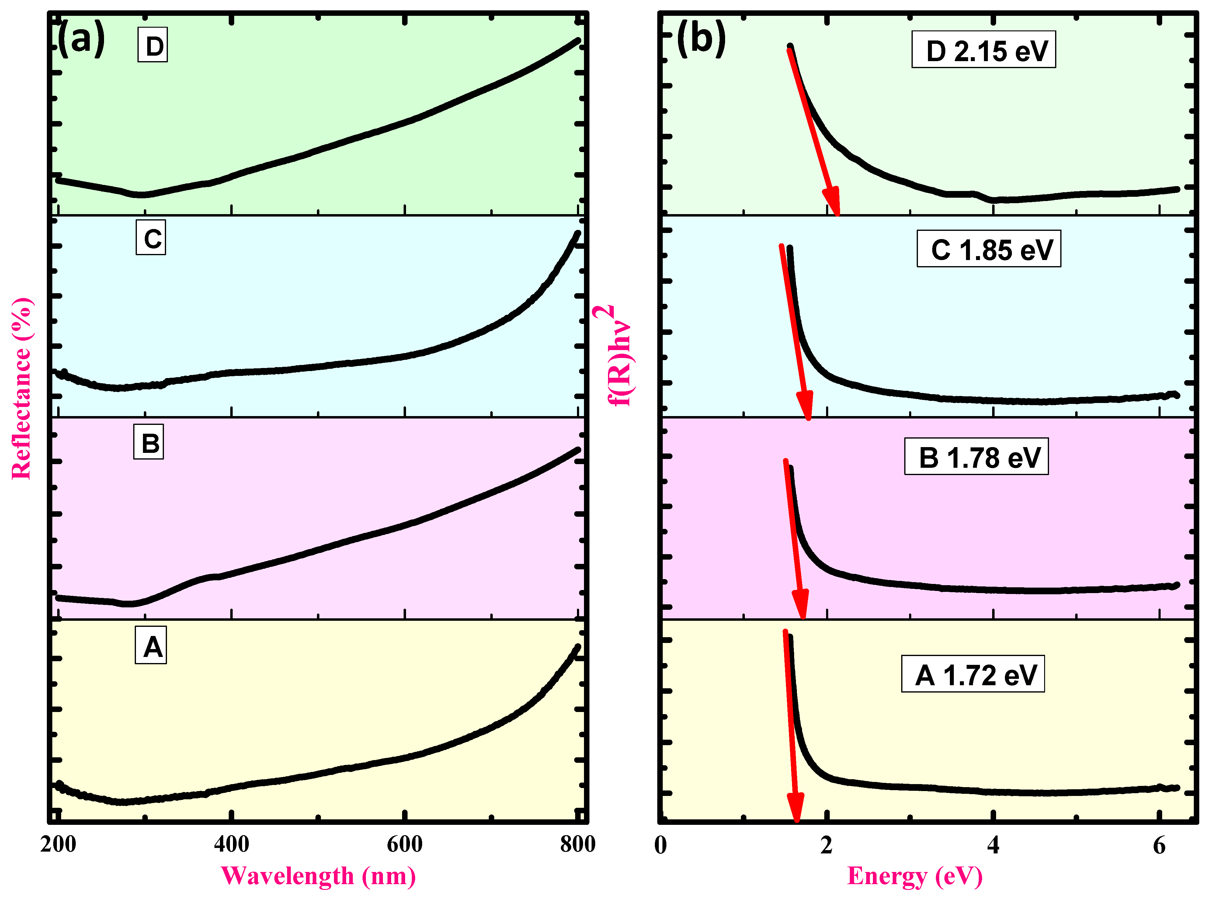
| ZnO Doping Concentration (%) | Crystal Size (nm) | d-Spacing (Aº) | Lattice Parameters (nm) | The Band Gap (eV) | Unit Cell Volume | |
|---|---|---|---|---|---|---|
| a = b | c | |||||
| 0 | 25 | 1.33 | 2.30 | 1.36 | 1.72 | 81.08A3 |
| 5 | 28 | 1.76 | 3.06 | 0.57 | 1.78 | 78.25A3 |
| 10 | 28 | 1.76 | 3.06 | 0.57 | 1.85 | 76.12A3 |
| 15 | 31 | 1.47 | 2.55 | 1.80 | 2.15 | 73.08A3 |
| S. No | Material | Pollutant | Irradiation Source | Discoloration Efficiency (%) | References |
|---|---|---|---|---|---|
| 1 | CuO-ZnO | Methylene blue | Halogen lamp | 82 | [83] |
| 2 | ZnO/CuO/SnO2 | Fast green | Visible light | 93.68 | [84] |
| 3 | Chitosan/CuO-ZnO | Rapid green | Solar light UV light | 60.23 91.21 | [85] |
| 4 | Silane-TiO2 | Methylene blue | UV light | 82 | [86] |
| 5 | CuO-ZnO | Rapid blue | UV light | 83.4 | Present work |
| Name of the Electrode | Charge-Transfer Resistance (RCt) (Ω) | The Capacitance of Double Layer (Cdl) (F) |
|---|---|---|
| CuO | 12.52 | 0.00156 |
| CuO + 5% ZnO | 10.61 | 0.00325 |
| CuO + 10% ZnO | 8.34 | 0.00786 |
| CuO + 15% ZnO | 11.96 | 0.000947 |
Disclaimer/Publisher’s Note: The statements, opinions and data contained in all publications are solely those of the individual author(s) and contributor(s) and not of MDPI and/or the editor(s). MDPI and/or the editor(s) disclaim responsibility for any injury to people or property resulting from any ideas, methods, instructions or products referred to in the content. |
© 2023 by the authors. Licensee MDPI, Basel, Switzerland. This article is an open access article distributed under the terms and conditions of the Creative Commons Attribution (CC BY) license (https://creativecommons.org/licenses/by/4.0/).
Share and Cite
BaQais, A.; Alam, M.W.; Farhan, M.; Muteeb, G.; Allag, N.; Mushtaq, S. Probe-Sonicated Synthesis of CuO–ZnO Hybrid Nanocomposite for Photocatalytic and Supercapacitor Applications. Inorganics 2023, 11, 370. https://doi.org/10.3390/inorganics11090370
BaQais A, Alam MW, Farhan M, Muteeb G, Allag N, Mushtaq S. Probe-Sonicated Synthesis of CuO–ZnO Hybrid Nanocomposite for Photocatalytic and Supercapacitor Applications. Inorganics. 2023; 11(9):370. https://doi.org/10.3390/inorganics11090370
Chicago/Turabian StyleBaQais, Amal, Mir Waqas Alam, Mohd Farhan, Ghazala Muteeb, Nassiba Allag, and Shehla Mushtaq. 2023. "Probe-Sonicated Synthesis of CuO–ZnO Hybrid Nanocomposite for Photocatalytic and Supercapacitor Applications" Inorganics 11, no. 9: 370. https://doi.org/10.3390/inorganics11090370
APA StyleBaQais, A., Alam, M. W., Farhan, M., Muteeb, G., Allag, N., & Mushtaq, S. (2023). Probe-Sonicated Synthesis of CuO–ZnO Hybrid Nanocomposite for Photocatalytic and Supercapacitor Applications. Inorganics, 11(9), 370. https://doi.org/10.3390/inorganics11090370