Article

An Experimental and Numerical Study of the Impact of Ambient Light of SiPMs in VLC Receivers

Department of Engineering Science, University of Oxford, Parks Road, Oxford OX1 3PJ, UK
*
Author to whom correspondence should be addressed.
Photonics 2022, 9(12), 888; https://doi.org/10.3390/photonics9120888
Submission received: 18 October 2022 / Revised: 18 November 2022 / Accepted: 18 November 2022 / Published: 22 November 2022
(This article belongs to the Special Issue Advances in Visible Light Communication)

Abstract

:
Silicon photomultiplier’s relatively large area and ability to detect single photons makes them attractive as receivers for visible light communications. However, their non-linear response has a negative impact on the receiver performance, including making them particularly sensitive to ambient light. Experiments and Monte Carlo simulations have been used to study this non-linearity. The resulting detailed understanding of the origins of the non-linear response leads to concerns over the accuracy of some previous simulations of SiPMs. In addition, it leads to simple methods to determine the maximum rate at which an SiPM can count photons and of determining the impact of a SiPMs non-linearity on its performance of a receiver. Finally, a method of determining which filters should be used to protect an SiPM from ambient light is proposed.

1. Introduction

Visible light communications (VLC) and optical wireless communications (OWC) have been proposed as approaches to increasing local wireless communications capacity using visible or optical wavelengths [1]. An important parameter for any communications system is the rate at which it makes errors. This is characterized by the bit error rate (BER), which depends upon the signal to noise ratio (SNR) at the output of the receiver. One approach to increasing the SNR of a VLC or OWC systems that are designed to operate at data rates of more than 100 Mbps is to use a silicon photomultiplier (SiPM) as a receiver [2,3,4,5,6,7,8,9,10,11,12,13,14,15,16]. These devices are arrays of microcells, containing a single photon avalanche diode (SPAD), and each microcell is designed so that an output pulse is generated whenever a photon initiates an avalanche event. It is the resulting ability to detect single photons which allows SiPM receivers to operate within a few photons per bit of the noise floor determined by Poisson statistics [5]. However, an intrinsic part of the microcell’s photon detection mechanism is the quenching of the avalanche process by reducing the bias voltage across its avalanche photodiode (APD). After the avalanche process has been quenched, the microcell has to be recharged so that another photon can be detected. Unfortunately, this means that the SiPM has a non-linear response [4].
SiPMs are commercially available with different characteristics, including area, numbers of microcells, photon detection efficiencies (PDEs), recharge times and output bandwidths, which are expected to impact their performance in receivers. The performance of receivers containing SiPMs can be determined experimentally [3,4,5,6,7,9,10,11,12,13,14,15,16]. However, these experiments should be performed very carefully and are time consuming. In addition, other parts of the system, particularly the transmitter, can have a significant impact on the performance of a system. Furthermore, even when this does not happen, it can be difficult to separate the impact of different SiPM characteristics. Finally, it is not always possible to test a receiver in some environments, for example, outside. These issues mean that a model or simulation of a SiPM receiver can complement experimental results.
Previously, SiPMs have been modelled using equivalent circuits or Monte Carlo simulations [17]. However, numerical methods, including Monte Carlo simulations, have been preferred when the performance of SiPMs in receivers is modelled. Some Monte Carlo simulations have focussed on the impact of the SiPM’s non-linear response on their ability to count photons [18]. However, this means that it is not necessary to take the finite width of the SiPMs output pulses into account. Furthermore, it was assumed that a microcell cannot detect photons whilst it is recovering [18]. Alternatively, the performance of SiPM receivers has been studied by evaluating relevant equations [19,20,21,22]. It should be possible to evaluate a series of equations in less time than it takes to perform Monte Carlo simulations. Unfortunately, sometimes these equations assume a feature, such as a digital output, which are not relevant to commercial SiPMs [19]. Alternatively, they are relevant to OFDM [22], which is not as energy efficient as on-off keying (OOK) [23] and currently gives a lower data rate than OOK at eye safe irradiances [14]. In other cases, the equations assume that, since the microcells are passively quenched, they are paralysable [18,20]. This assumption is correct when the microcells have a digital output [19], but, commercial SiPMs have analog outputs and they are therefore not necessarily paralysable. To create a simulation that is based upon the fewest possible assumptions, a Monte Carlo simulation of the physical processes in a SiPM has been created.
The parameters in the simulation are obtained from either the relevant data sheet or the experimental results. The results of the simulations are then validated by comparing them to the results of the experiments. In particular, they are compared to the measurements of the bias current needed to sustain an over-voltage on the SiPM and the impact of ambient light on the performance of receivers containing SiPMs. The simulation results are then used to show that microcells are able to detect photons whilst they are recharging. The simulation results also lead to a new simple method of predicting the impact of the non-linear response of the SiPM on receiver performance in ambient light and a method for selecting optical filters that should be used in receivers. In the future, it should be possible to use the Monte Carlo simulation to devise an efficient means of compensation for any SiPM non-linear caused by the transmitted data or to predict the performance of receivers containing existing or future SiPMs in a wide variety of situations.
This paper is organized as follows. Section 2 contains descriptions of the operation of a SiPM, the experimental procedure used to test receivers containing SiPMs and the Monte Carlo simulation. This is followed in Section 3 by the results of the experiments to determine the voltage dependence of the microcells PDE. This section also contains the results of the experiments to determine either the irradiance dependence current needed to sustain an over-voltage or the impact of ambient light on the performance of receivers containing SiPMs. In both cases, these experimental results are compared to the results of Monte Carlo simulations of the same experiments. Finally, Section 4 contains results which show that microcells can detect photons before they are fully charged. Results are also presented which show that despite this behavior, the maximum count rate of an SiPM can be determined using an equation that was derived assuming that there was a minimum time between photons that could be detected, a time previously known as the dead time. The non-linear response of the SiPM is then shown to arise from a combination of changes to the average PDE and microcell charge when photons are detected. This leads to a simple method of predicting the impact of the SiPM’s non-linearity on the performance of a receiver in ambient light. Finally, this section includes a suggested method for selecting optical filters to use with SiPMs in receivers and a discussion of the possible future uses of the Monte Carlo simulation.

2. Experimental Procedure and Monte Carlo Simulation of SiPMs

2.1. Description of SiPMs and Their Response to Light

A SiPM is an array of microcells that is connected in parallel. Each microcell contains an APD which is biased above its breakdown voltage, Vbreakdown, by an amount known as the over-voltage, Vov. The probability that an avalanche will occur [24] means that the PDE of a microcell can be calculated using
P D E ( λ , t ) = P D E max ( λ ) × ( 1 exp ( V ov ( t ) / V char ) )
where V ov ( t ) is the instantaneous over-voltage, P D E max ( λ ) is the maximum possible PDE at a particular wavelength and V char is a characteristic voltage at this wavelength for the APD.
If the over-voltage is positive and the microcell only contained an APD, then a photon could initiate a self-sustained avalanche event. This means that only one photon could be detected. This avalanche event therefore has to be quenched so that other photons can be detected. In the case of the commercially available SiPMs manufactured by Broadcomm, Hamamatsu and Onsemi, a resistor is placed in series with the APD within each microcell. Consequently, the current caused by an avalanche process results in a voltage drop across the resistor, which reduces the voltage across the APD. Once this voltage equals the APDs breakdown voltage, the self-sustained avalanche process is quenched. The capacitance in the microcell is then recharged via this resistor and the resistance between the microcell and the source of the SiPM bias voltage. This means that the recharging process can be represented by the equation
V ov ( t ) = V ov ( 1 exp ( t / τ R C ) )
where t is the time since the avalanche process was quenched and τ R C is the time constant for the recharging process. This time constant can be determined from individual pulses that occur when photons are detected and is typically tens of nanoseconds. If the capacitance of the microcell is Ccell, then the additional charge stored in the microcell will be CcellVov. The results in Figure 1 show that the sensitivity of the PDE to the over-voltage means that it recovers more quickly than the over-voltage. Since the additional charge stored on the microcell is proportional to the over-voltage, the PDE also recovers more quickly than the additional charge stored in the microcell.
Photons can be detected by monitoring the bias current that flows into the SiPM to recharge each microcell. This current flows because the microcell is discharged when it detects a photon, and since the amount of charge on the microcell is independent of the photon wavelength, the current is independent of the wavelength of the detected photon. If the interval between photons being detected by the SiPM is significantly longer than τ R C , then each detected photon results in a pulse with a fast rising edge, followed by the exponential decay expected from Equation (2). This mechanism can be used to detect and count photons using any of the commercially available SiPMs.
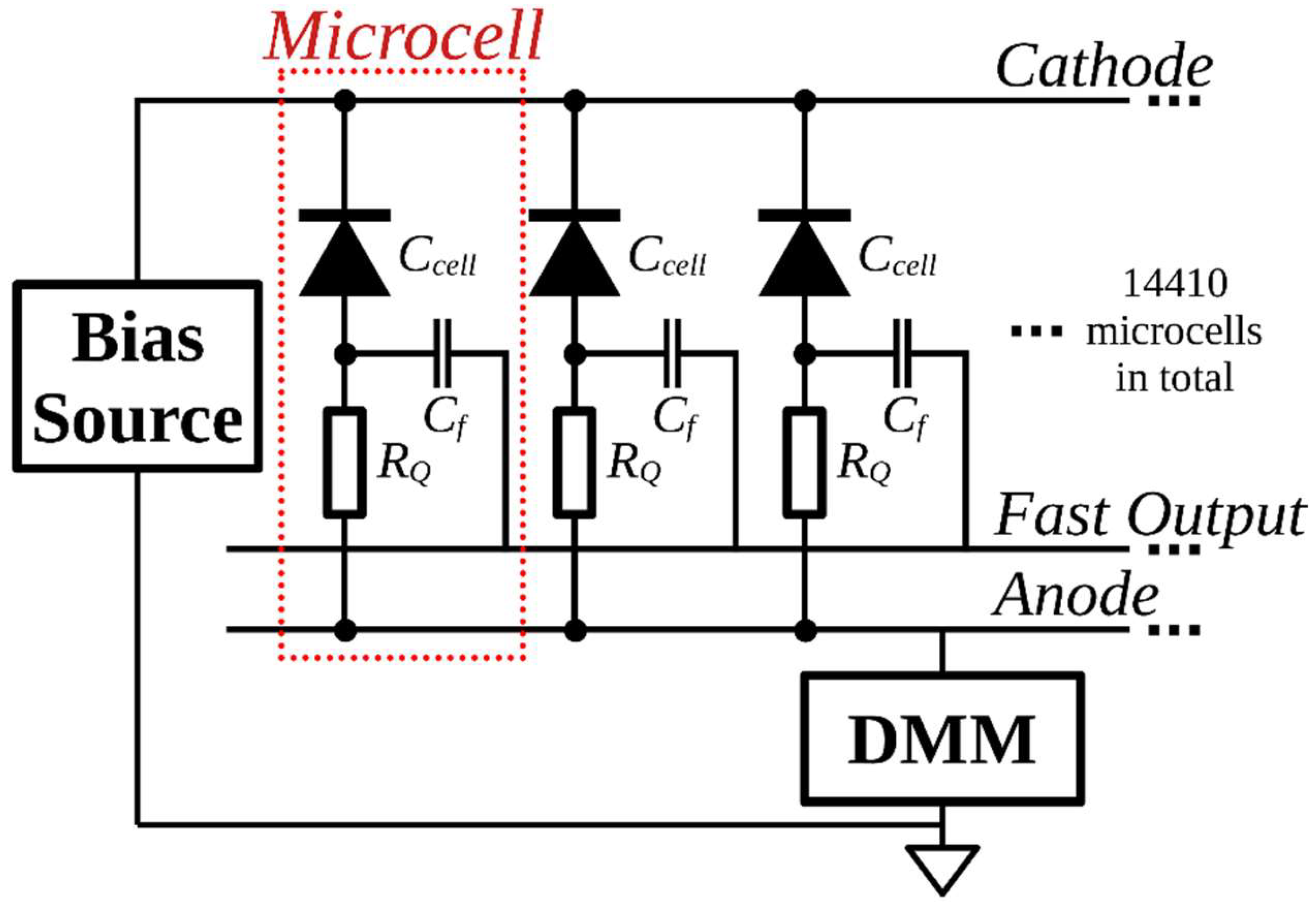
Figure 2 is a schematic diagram showing how a bias voltage was applied to a SiPM manufactured by Onsemi and how a digital multimeter was connected to measure the current flowing to sustain this voltage. This figure also shows that these particular SiPMs have an output known as the fast output. In addition, a second output can be created by placing a resistor between the SiPM’s anode and ground. This output is equivalent to the output of SiPMs manufactured by other companies and it is possible to detect individual photons using this output. However, the width of the voltage pulses on this output is determined by the recharge time constant of the microcells. Since this time is longer than the fast output pulse width, this output is referred to as the slow output.
As shown in Figure 2, the fast output is created by capacitively coupling a common output to the connection between the APD and the quenching resistor in each microcell [25]. This capacitive coupling means that the signal on this fast output line is proportional to the rate of change of the voltage across the APD. The charging of the node between the APD and the resistor form the slow output pulses. This capacitance therefore means that the pulses on the fast output are a high pass filtered version of the slow output pulses. This removes the dc level component of the signal and explains why the fast output pulses are at least an order to magnitude narrower than the pulses on the slow output.
At low irradiances, each microcell has time to recover before the next photon is detected and the SiPM has a linear response. However, increasing the irradiance falling on the microcells reduces the average time between successive photons passing through each microcell. Eventually, photons arrive at microcells whilst they are still recharging. The result is that the SiPM has a non-linear response. Previously, this non-linear response has been observed by measuring the bias current needed to sustain the over-voltage on the SiPM as the irradiance falling on the SiPM is increased [10].

2.2. Experimental Procedure

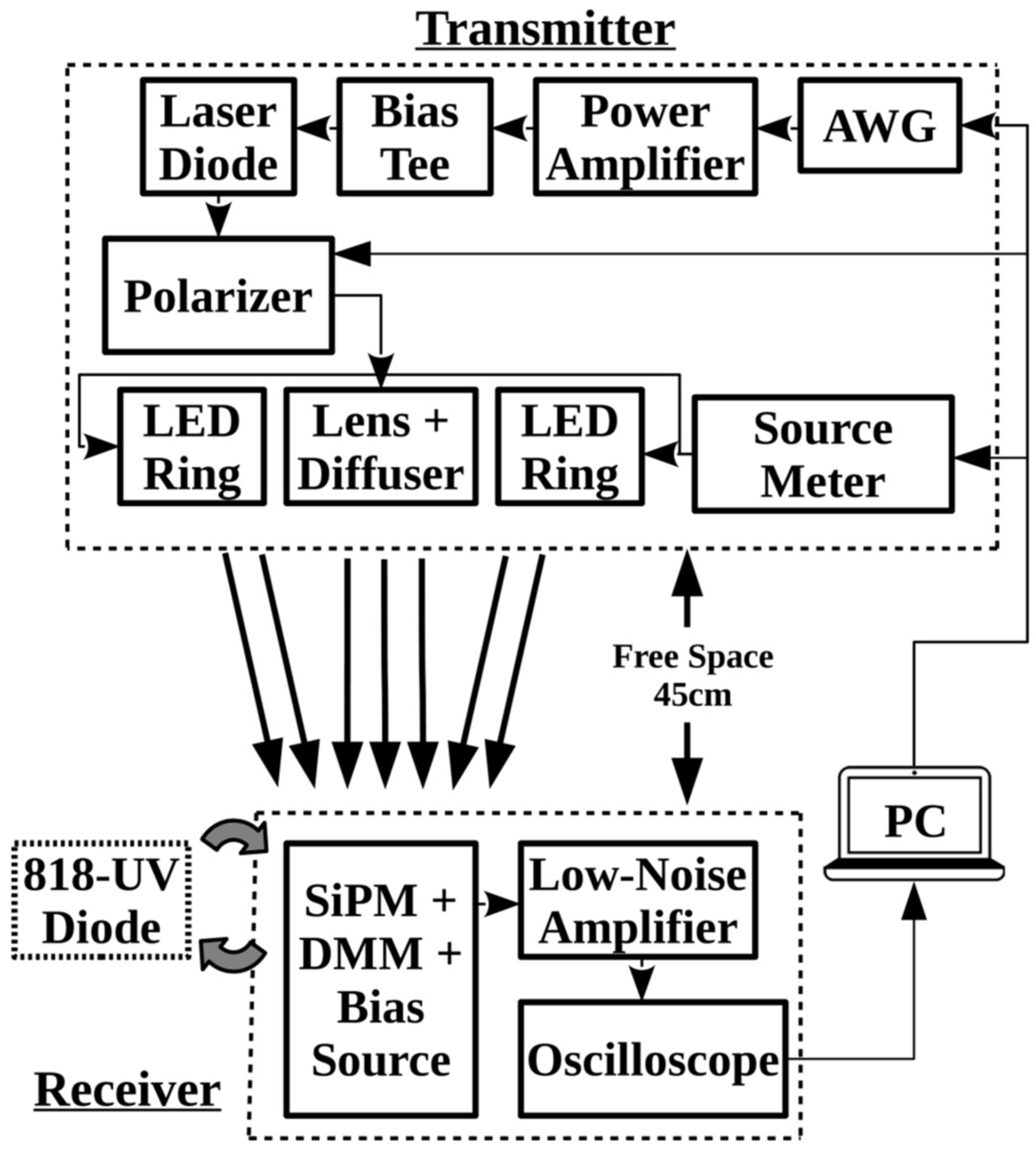
A schematic diagram of the equipment used to characterise a SiPM and determine its performance as a VLC receiver is shown in Figure 3. Previously, experiments were performed with J series SiPMs mounted on SMA evaluation boards. These boards are convenient to use. However, they contain a resistor in series with the SiPM so that slow output pulses can be detected. Unfortunately, this resistor both increases the time needed for each microcell to recharge and decreases the effective over-voltage, and hence PDE, at high irradiances [16]. Since the fast output is used for data transmission experiments, this resistor is not needed. More recently, experiments have therefore been performed using a J series 30020 SiPM mounted on an SMPTA board, whose key characteristics are listed in Table 1. Without a resistor in series with the SiPM, the SMTPA boards have a shorter recharge time, and their PDE is not degraded at high ambient light levels. This means a SiPM on an SMTPA board is both easier to model and, more importantly, is a better receiver. As shown in Figure 2, in the absence of a resistor in series with the SiPM on the SMPTA board, the current needed to sustain the over-voltage was measured with a Keithley 196 digital multimeter.
To obtain reproducible results from data transmission experiments, particular care had to be taken to minimize the impact of RF interference. When the beam from the transmitter to the receiver was blocked, a 5 mVpp interference signal was initially observed. Since the signal when a photon was detected was 15 mVpp, this level of interference was unacceptable. A near field probe was therefore used to determine that the source of the interference was the transmitter. The optical cage system containing the transmitter and the SMA cable connecting the transmitter to the AWG was therefore covered with a metallized cloth and the probe was then used to confirm that this cloth prevented this type of interference.
Even with this precaution, it was sometimes impossible to obtain reproducible BER measurement results consistently. By watching the oscilloscope as it captured data, it became clear that a 20 mVpp signal occurred frequently enough to explain the difficulties in reproducing results. A subsequent investigation showed that the frequency spectrum of this intermittent interference was consistent with it being caused by Wi-Fi and other RF signals transmitted by colleagues’ electronic devices. The experimental procedure was therefore changed so that any data captured when there was a significant level of this interference was discarded and the data was transmitted again. However, there was so much interference during normal working hours that most results were captured overnight.

2.3. Monte Carlo Simulation of an SiPM

Results from experiments with a 30020 on an SMPTA board have been compared to results from a Monte Carlo simulation of this SiPM. These simulations were performed with a time variable that increased by the minimum of one twentieth of a nanosecond and one twentieth of the bit time of the OOK data. Since the charge on the microcell and the microcell’s recovery are independent of the detected photons wavelength, all the simulated photons are assumed to have the same wavelength as the transmitters’ output. This means that the impact of ambient light is represented by the irradiance at this wavelength, which gives rise to the same count rate.
In some simulations, the irradiance on the SiPM was assumed to be constant. However, when simulating data transmission experiments, the irradiance was modulated to represent OOK data. At each time, the instantaneous irradiance, the bit time and the Poisson probability density function
P o i s s o n ( n ) = m n e m / n !
were used to determine the number of photon incidents on the SiPM in a bit time, n, where m is the mean of the distribution. At a time, t, this mean was calculated using
m ( t ) = ( L T X ( t ) + L a m b ( t ) ) A S i P M . d t / E p  
where L T X ( t ) is the irradiance from the transmitter at time t and L a m b ( t ) is the irradiance representing ambient light at the same time. In addition, d t is the time step used in the simulation, E p is the energy of a photon from the transmitter and A S i P M is the area of the SiPM. The n photons calculated using (3) and (4) were then randomly distributed in the bit time. This was done using a random number with a Poisson distribution so that the time between photons had the required exponential distribution.
Once the photon stream had been generated, an event-driven Monte Carlo simulation was started and the following quantities were calculated:
(i) The total charge on all microcells.
Q t o t a l ( t ) = n = 1 N c e l l s C c e l l V o v ( n , t )
where C c e l l is the capacitance of a microcell and Vov(n,t) is the over-voltage on the nth microcell at time t.
(ii) The average charge on the microcells that have detected a photon at this time. In this case, (5) is evaluated, but only the microcells that have detected a photon at this time are included in the summation. This sum is then divided by the number of microcells that have detected a photon at this time.
(iii) The instantaneous current needed to recharge each microcell was calculated by multiplying the increase in the over-voltage for each microcell since the previous time by the microcell capacitance and dividing the result by dt. The total current was then calculated by adding all these contributions; hence
I b i a s ( t ) = n = 1 N c e l l s { C c e l l d t ( V o v ( n , t ) V o v ( n , t d t ) )     i f   V o v ( n , t ) > V o v ( n , t d t ) 0                                                                   o t h e r w i s e
(iv) The proportion of microcells that are fully charged was calculated by determining the proportion of microcells whose over-voltage was more than 99% of the maximum over-voltage.
(v) The average PDE of all the microcells was determined using (1) the instantaneous PDE of each microcell and then calculating the average value.
The simulation started by initiating the microcells in the SiPM into a state that is consistent with the initial irradiance. The simulation was then evolved by up-dating the over-voltage and PDE of each microcell using Equations (1) and (2) until the time at which the next photon or photons are incident on the SiPM. At each of these times, the first step was to use a uniformly distributed random number to determine which microcell might detect the photon. The instantaneous PDE of the selected microcell and a second random number were then used to determine if the photon was detected. If the photon was detected, the over-voltage and PDE of the microcell were both instantaneously set to zero. In addition, the charge on this microcell was added to the sum of the charge on microcells that had detected a photon at this time. This process was then repeated for all photons incident on the SiPM at the same time. Once the process of detecting photons at a particular time had been completed, all the quantities of interest were calculated. The simulation was then evolved until the time when the next photon or photons were incident on the SiPM. This process was then repeated until the end of the simulated time.
At the end of the simulation, the sum of the charge on microcells that detected photons at each time was convolved with a Gaussian kernel, which represented the fast output pulses. The result was a fast output pulse whose integral is proportional to the charge discharged by all the photons detected at a particular simulated time. If the incident irradiance was modulated to represent OOK data, the resulting simulated fast output was processed in the same way as the fast output from a SiPM in an experiment.
When writing the simulation, a decision was made not to include three non-ideal behaviors of SiPMs, specifically dark counts, after-pulsing and optical cross-talk. Dark counts are spontaneous avalanche events that occur in the dark and in the 30020 they occur at a rate of 1 MHz [26]. This is much smaller than the anticipated rate at which ambient light photons are detected and so it was not included in the simulation. After-pulsing occurs when a charge carrier initiates an avalanche event in the same microcell after being temporarily trapped in the high field region of the microcell [17]. Similarly, cross-talk occurs when a secondary photon produced by an avalanche event initiates an avalanche in another microcell either immediately or after a delay [17]. In a 30020, the cross-talk occurs after less than 7.5% of avalanche events and after-pulsing after less than 5% of avalanche events. It is not clear from this data if these effects needed to be included to achieve the required modelling accuracy. Furthermore, the data required to model the delays in these effects is not provided by the manufacturer. The pragmatic decision was therefore taken to create a numerical model that excluded these effects and then reconsider this decision once its results had been compared to experimental data. The results in Section 3.3 and Section 3.4 suggest that it is not necessary to include these effects in the Monte Caro simulation.

3. Results

3.1. Photon Detection Efficiency Measurement

One piece of important information required for an accurate Monte Carlo simulation of a SiPM is the relationship between PDE and over-voltage. Figure 4 shows PDE measurement results, obtained when the 405 nm irradiance on a 30020 J-series SiPM was constant at 2.4 mWm−2, and the bias voltage varied. This irradiance was selected to stimulate avalanches at a rate which dominates the dark count rate while remaining in the SiPM’s linear region. The bias current at this irradiance and for each over-voltage,   I b i a s ( V o v ,   L ) , was then measured and the PDE, η ( V o v ,   λ ) , was then calculated using [16].
η ( V o v ,   λ ) = E p I b i a s ( V o v ,   L ) C c e l l V o v A S i P M L
In this figure, the experimental results are compared to Equation (1) with parameters P D E m a x ( λ ) = 0.46 and V c h a r = 2.03   V . The excellent agreement between the experimental results and those predicted using these parameters meant that these parameters were used in Monte Carlo simulations.

3.2. Measured Bias Current

Another key parameter in a simulation is the capacitance of the microcells. Since this is the capacitance of a reverse bias APD, it may be voltage dependent. The bias current needed to sustain the voltage applied to the SiPM saturates when the time between detected photons is comparable to the microcell RC time constant. However, before saturation occurs, this bias current is related to the rate at which photons are detected by
I b i a s = C r a t e   × C c e l l × V o v    
where   C r a t e is the rate at which photons are being counted,   C c e l l is the capacitance of a microcell and V o v is the over-voltage.
For monochromatic light an irradiance, L , can be converted to a photon flux per unit area by dividing the irradiance by the energy of each photon, E p . The number of photons per second incident on a SiPM can then be determined by multiplying the result by the area of the SiPM,   A SiPM . If η ( V o v ,   λ ) is the PDE of the SiPM at the wavelength of the incident light, then at low irradiances, the count rate of photons is
C r a t e   = η ( V o v ,   λ ) A SiPM   L   / E p
Then, if the capacitance of the microcell is independent of the over-voltage, the resulting bias current is
I b i a s = η ( V o v ,   λ ) A SiPM   C c e l l   V o v L / E p
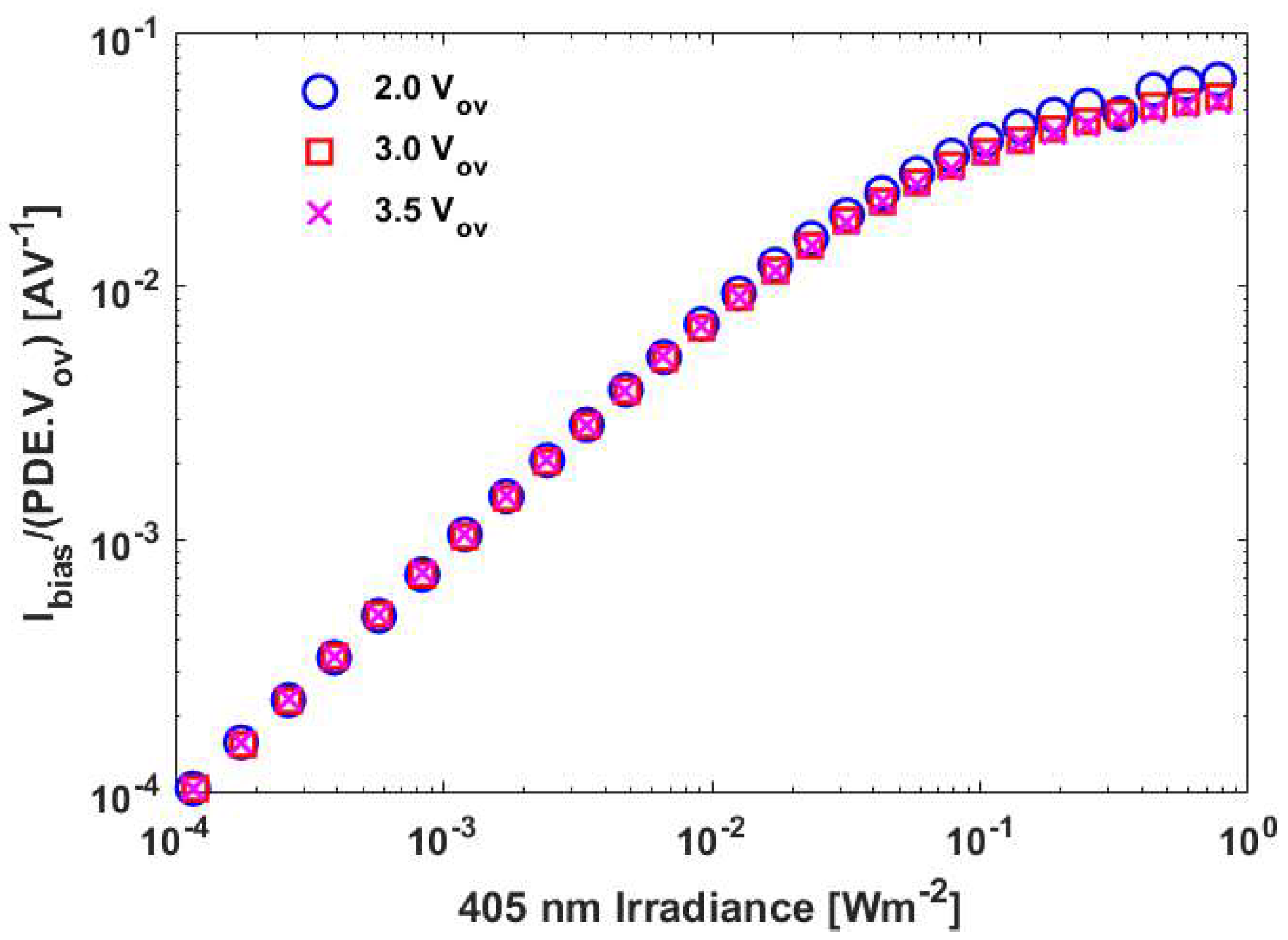
This equation shows that if the microcell capacitance is independent of over-voltage, then, at low irradiances, the current will be proportional to the product of the PDE and the over-voltage. Figure 5 shows the current measured at different over-voltages divided by the product of the over-voltage and the PDE at that over-voltage. The important conclusion from the results in this figure is that the microcell capacitance is independent of the over-voltage. Equation (10) and the measured bias current at low irradiances has therefore been used to determine the capacitance of each microcell. As shown in Table 2, the resulting value, 46 fF, was one of the parameters used in the Monte Carlo simulation.

3.3. Comparison of Measured and Simulated Bias Currents

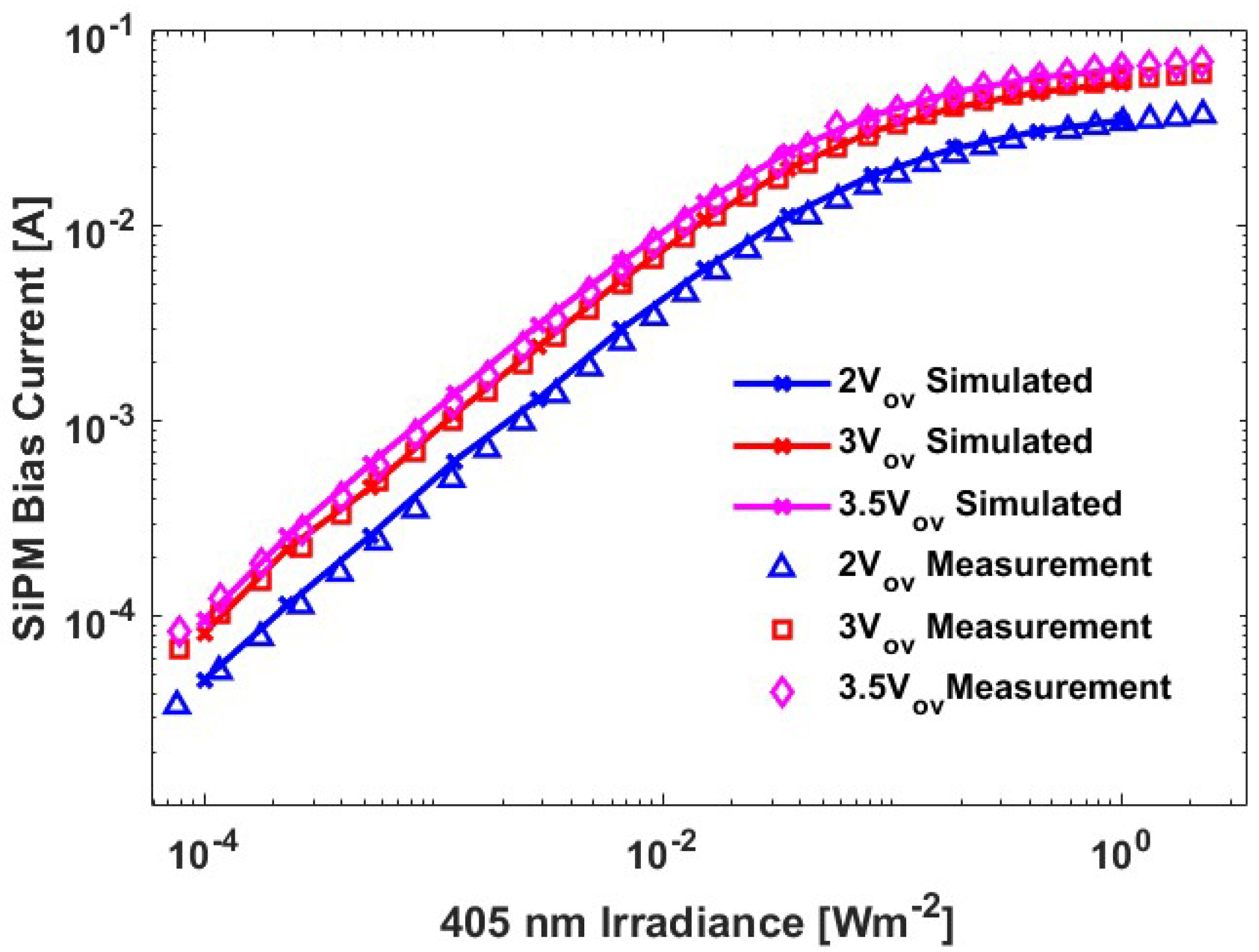
The voltage dependence of the photon detection efficiency and microcell capacitance obtained from experiment data have been incorporated into the Monte Carlo simulation of the current needed to sustain over-voltages of 2.0 V, 3.0 V and 3.5 V. The results in Figure 6 show an excellent agreement between these simulated currents and the experimental results.

3.4. Data Transmission Experiments in Ambient Light

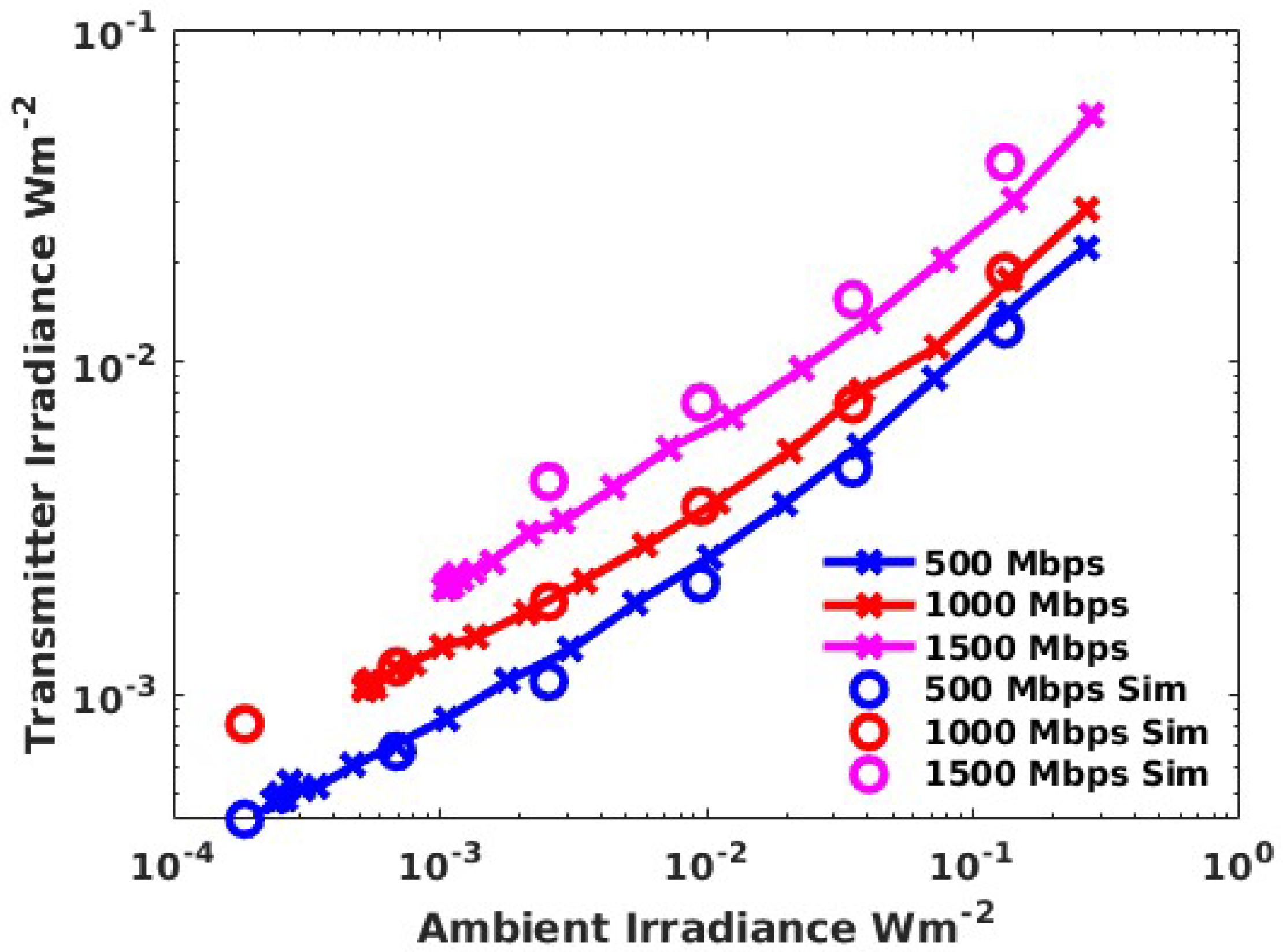
Figure 7 shows the results of experiments to determine the irradiance from the transmitter required to achieve a BER of 3.8 × 10⁻³ when the ambient light irradiance increases. Eye safe transmitters have been described providing a radius of horizontal coverage in a typical office of 2 m and which provide a minimum transmitter irradiance at 405 nm of 2 mWm−2 [11]. Figure 7 shows that with this transmitter irradiance, it is possible to support data rates up to 1.5 Gbps with a BER of 3.8 × 10⁻³. However, as the data rate increases, the ambient light irradiance which may be tolerated decreases. In particular, with a transmitter irradiance of 2 mWm−2, ambient irradiances of up to the equivalent of 1 mWm−2, 3 mWm−2 and 5 mWm−2 of 405 nm light are tolerated at 1.5 Gbps, 1 Gbps and 500 Mbps.
The dominant noise source in a SiPM receiver is expected to be Poisson noise. If this is the case, the BER when an on-off keyed signal is transmitted can be calculated using [5]
BER = 1 2 [ k = 0 n T ( N Tx + N b ) k k ! . e ( N Tx + N b ) + k = n T ( N b ) k k ! . e N b ]
where N b is the average number of photons detected per bit time when a zero is received, N T x is the number of additional detected photons per bit time needed from the transmitter when one is received and n T is the threshold used to differentiate a one from a zero. The value of n T that minimizes the BER has to be determined for particular combinations of N b and N T x .
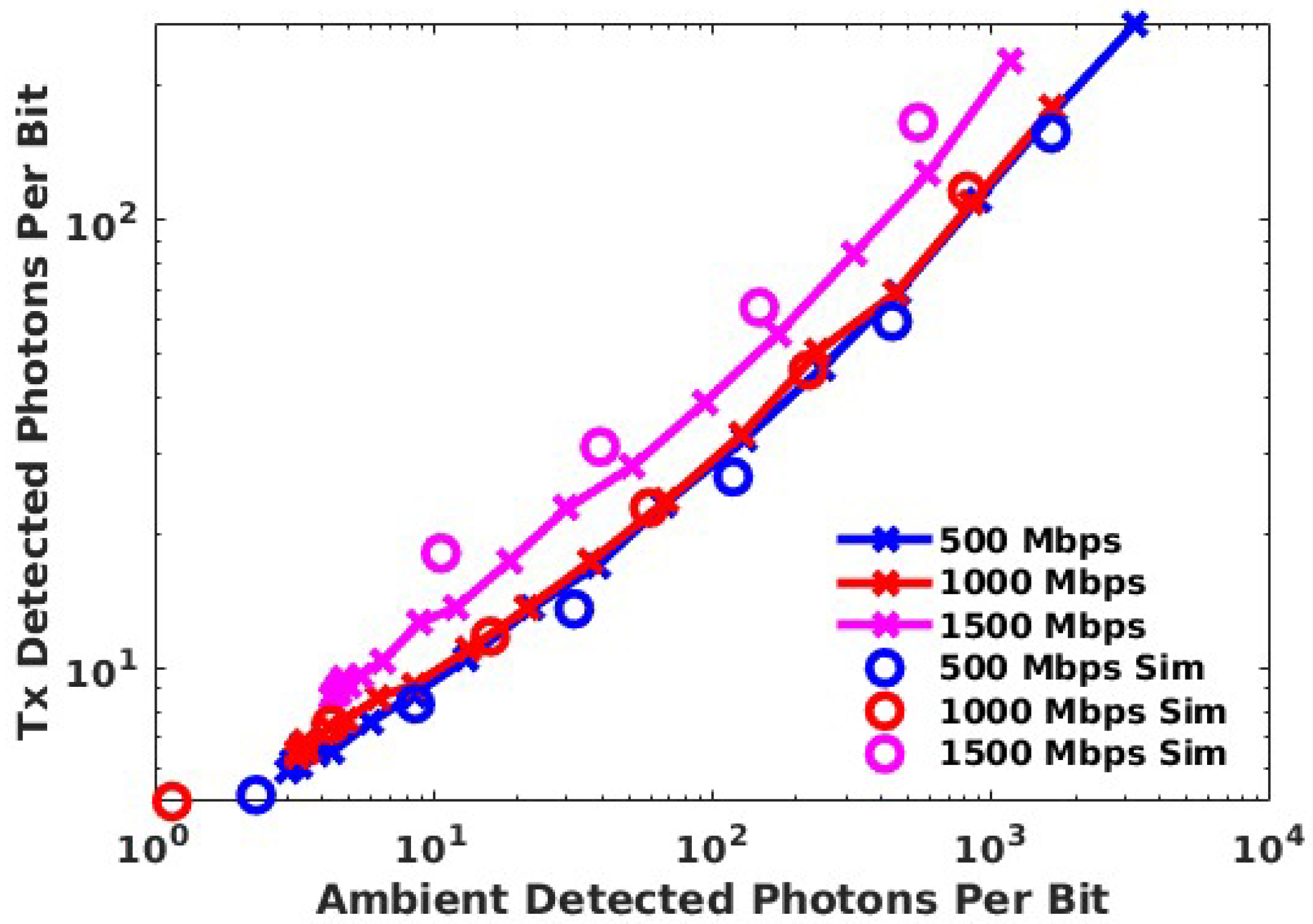
Equation (11) shows that the important parameters are the numbers of detected photons per bit when a zero and a one are received. These parameters have therefore been used as the axes in Figure 8 to show the results of experiments during which the ambient light level, and hence the number of photons detected when a zero is transmitted, was varied. As expected from (11), using this x-axis, the results for 500 Mbps and 1000 Mbps fall on the same curve. However, the results for 1500 Mbps suggest that there is a relatively small, but noticeable, power penalty for this data rate. This may be caused by the width of the SiPM fast pulses or the limited bandwidth of another part of the link.
In addition to the experimental results, Figure 8 also shows the results of Monte Carlo simulations of these experiments. Excellent agreement is obtained for data rates of 500 Mbps and 1000 Mbps. However, the agreement is not as good for 1500 Mbps. The simulation included the width of the fast output pulses and the difference between the simulated 1000 Mbps and 1500 Mbps results. These results show that the width of the output pulses is starting to have an effect at data rates above 1000 Mbps. The difference between the results from experiments and the simulations at 1500 Mbps must therefore be due to something that has not been included in the simulations, for example the bandwidth of the transmitter. More importantly, the results in Figure 8 confirm that, if the links performance is determined by the SiPM, then its performance can be predicted using this Monte Carlo simulation.

4. Discussion

4.1. The Origins of the SiPMs Non-Linearity

The count rate for a SiPM such as the 30020 can be related to the irradiance of monochromatic light falling on the SiPM, L , by [10]
C rate   = N cells α   L / ( 1 + α   τ p   L )
where N cells is the number of microcells and τ p is a characteristic time. In addition, the parameter α is
α = η ( V o v ,   λ ) A μ E p      
where η ( V o v ,   λ ) is the photon detection efficiency of the SiPM at a particular over-voltage and wavelength and V o v , is the over-voltage, E p is the energy of each photon and A μ is the active area of a microcell.
Equation (12) was suggested as a function which is consistent with the SiPM having a linear response at low irradiances and a saturated response at high irradiances. Furthermore, when (12) was suggested, it was assumed that each microcell cannot detect a photon whilst it was being recharged [4]. The latter assumption meant that previously the parameter τ p was referred to as the dead-time for the microcell [4].
The assumption that a microcell cannot detect a photon until it is fully recharged means that a charge C cell   V ov is discharged when a photon is detected. Consequently, the bias current needed to sustain the over-voltage is
I bias   = C cell   V ov   N cells α   L / ( 1 + α   τ p   L )
Previously, this equation has been shown to agree with experimental results [10]. It therefore appears that the assumption that a microcell cannot detect a photon whilst it is recharging is correct and this assumption has been used to simulate SiPMs in receivers [19,22,27].
One advantage of developing a detailed Monte Carlo simulation is that it allows users to understand the physical processes occurring in microcells in detail. Figure 9 shows the behavior of a microcell when the average time between detected photons is longer than the time that the microcell needs to fully recharge. As expected, in these circumstances, the microcell is usually fully recharged before it detects a photon. However, the results in Figure 9 show a photon being detected when the microcell is only partly recharged. This event clearly shows that, despite the concept of dead time leading to an equation, Equation (14), that fits the measured bias current data, microcells can detect photons when only partially recharged. Some conclusions arising from any simulations which assume that microcells are unable to detect photons whilst they are recharging will therefore not be reliable. In addition, it should be possible to improve on any methods to compensate for the impact of the non-linearity which arises from these simulations.

4.2. A Simple Method of Estimating the Maximum Count Rate

Although the concept of dead time, which was part of the derivation of (14), is not accurate, this equation has been shown to agree with the measured bias current data. An important aspect of the derivation of Equation (14) [4] was that it assumed that there was a minimum time between photons that a microcell could detect, τp. However, this parameter was not related to the recharge time of the microcell and it was therefore used to fit (14) to a particular set of experimental data.
The reason why it has previously been possible to show agreement between (14) and the experimental results can be understood by considering the current flowing when the SiPM response is saturated. Saturation occurs when the denominator of (14) is dominated by the second term and the resulting current when the SiPM saturates is
I sat   = N cells C cell V ov / τ p  
This means that
( I sat ( V ov 1 ) / V ov 1 ) / ( I sat ( V ov 2 ) / V ov 2 ) = τ p ( V ov 2 ) / τ p ( V ov 1 )
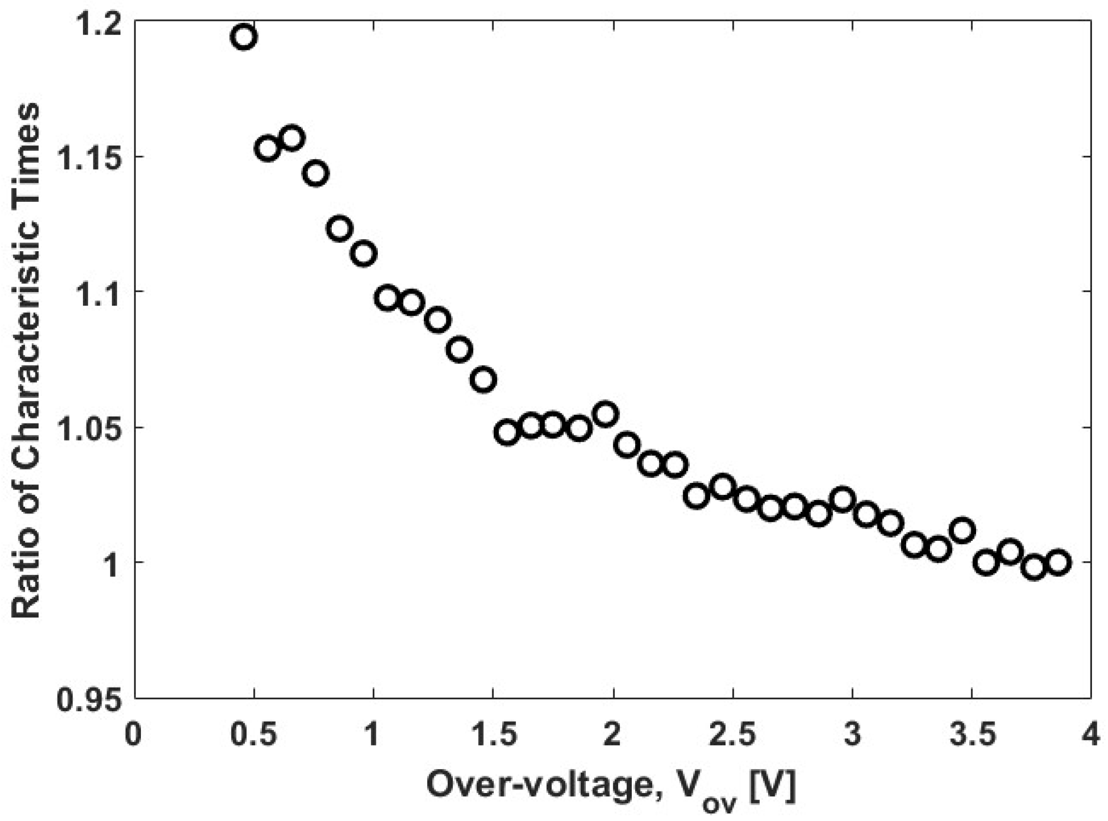
Consequently, the ratio of characteristic times needed to fit (14) to bias currents measured at different over-voltages can be determined from (16). This ratio of characteristic times has been determined for a wide range of over-voltages. The results in Figure 10 show that, once the over-voltage is more than 1.5 V, this characteristic time is almost constant. This means that, for the range of over-voltages that are typically used, the maximum count rate of a SiPM can be estimated using
C max   = N cells / τ p                            
where τ p is approximately 2.2 times the RC time constant of the microcells [10].

4.3. A Simple Method of Predicting the Impact of Ambient Light

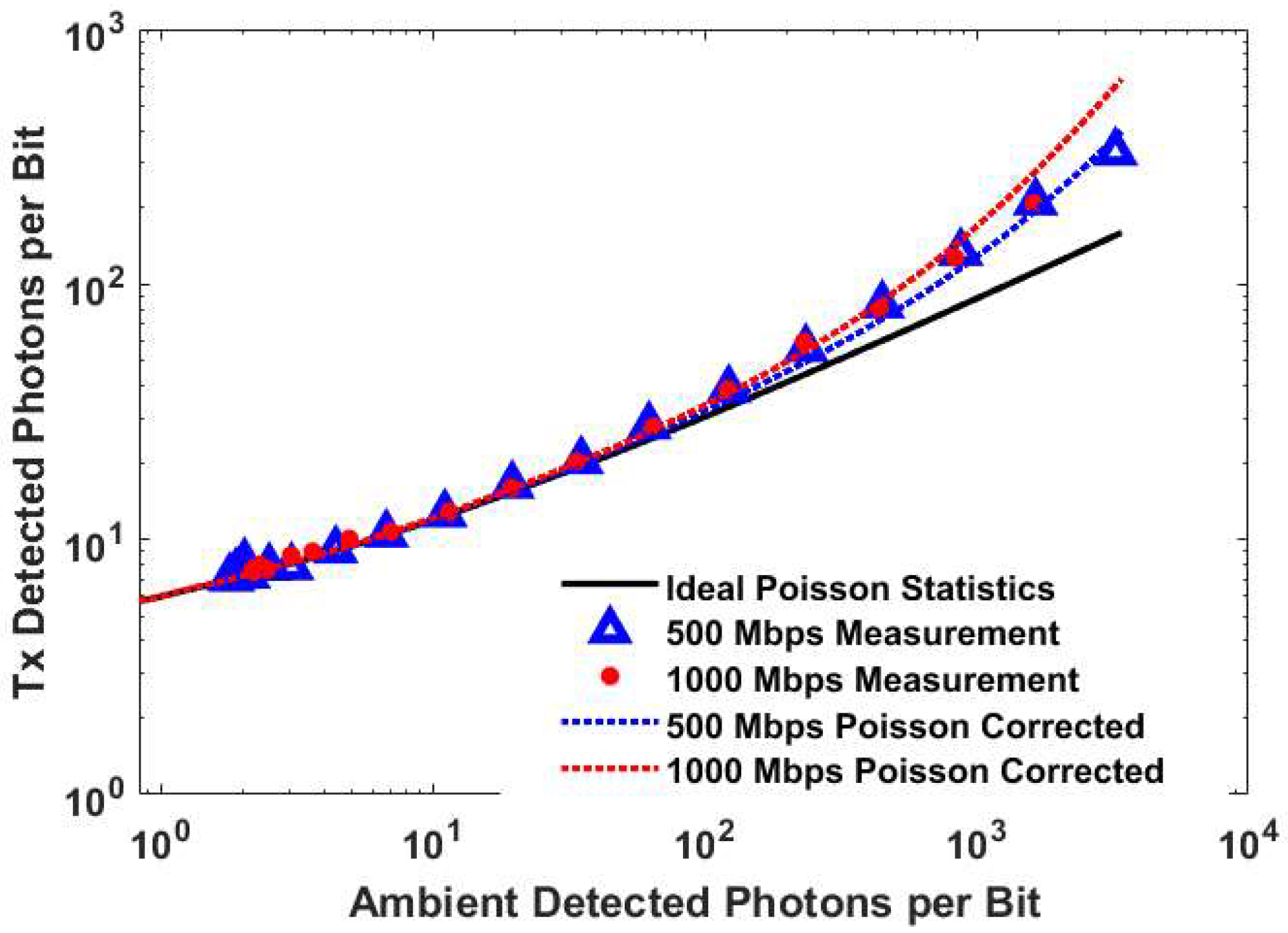
The results in Figure 7 and Figure 8 show that the results of the Monte Carlo simulations can be used to predict the results of data transmission over a wide range of ambient light conditions. However, each simulation can take an inconvenient time. An even simpler prediction method would therefore be advantageous. The experimental results for the two data rates, 500 Mbps and 1000 Mbps, for which the VLC systems performance is determined by the SiPM alone are shown in Figure 11. This figure also includes the performance of these systems predicted using the SiPM parameters and (11). The results in this figure show that the performance of the SiPM receiver at 500 Mbps and 1000 Mbps can be predicted using Poisson statistics until approximately 100 detected ambient light photons per bit. However, by 1000 detected ambient light photons per bit, there is an error of a factor of approximately two in the prediction. If the photon detection efficiency is 0.35, then 1000 detected photons per bit corresponds to an irradiance of 78 mWm−2.
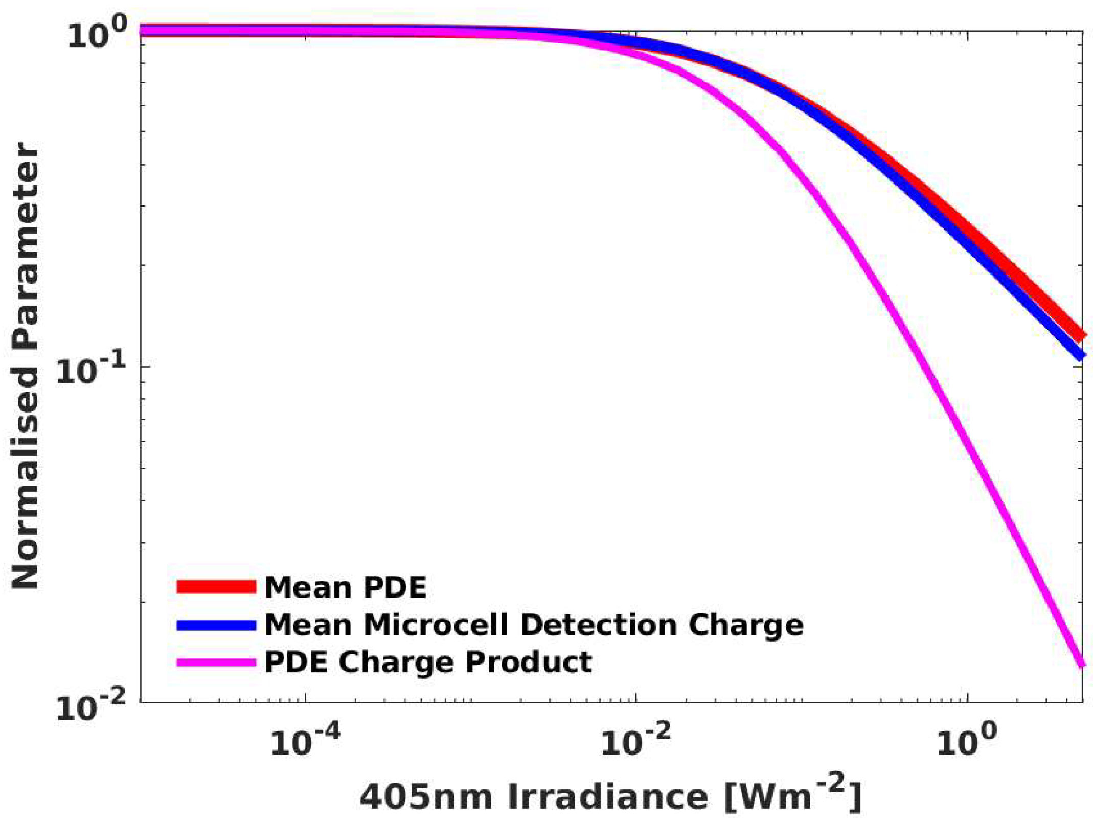
Figure 9 shows that photons can be detected before a microcell is fully charged and, hence, whilst the microcells’ PDE is less than its maximum value. Furthermore, as the irradiance increases, more microcells will detect photons whilst their PDE is less than the maximum. The average PDE of the array at times when photons are detected has been calculated for different simulated irradiances. The results in Figure 12 show that, as expected, when the irradiance is high enough, this array average PDE when any photon is detected decreases. This change in the array average PDE alone might explain the non-linear response of the SiPM. However, the irradiance at which the array average PDE falls to half its maximum value is 193 mWm−2. In contrast, the current falls to half the value expected from its linear response when the irradiance is 73.6 mWm−2. The change in the array average PDE when photons are detected cannot therefore be the only mechanism contributing to the SiPMs non-linear response.
An important assumption in the Monte Carlo simulation is that the height of the fast output pulse generated when a photon is detected is proportional to the charge on the microcell when that photon is detected. This means that the smaller charge stored on a microcell when it detects a photon before it is fully recharged may contribute to the non-linear response of both the bias current and the fast output used when the SiPM is a receiver. This may explain why the irradiance at which the transmitters sensitivity is half the expected value, 78 mWm−2, is similar to the irradiance at which the measured bias current is half the expected value.
It appears that the charge stored when a photon is detected contributes to the SiPMs’ non-linearity. The average charge stored on a microcell when it detects a photon has therefore been calculated at different irradiances. The results in Figure 12 show that this effect is as significant as the change in the array average PDE when a photon is detected. Consequently, when the two processes are taken into account, the average signal per incident photon falls to half its maximum value at an irradiance of 65 mWm−2, which is much closer to the irradiance at which the bias current is half the value expected from its linear response.
The origin of the fast output pulses and the results in Figure 12 suggest that the non-linearity in the bias current should also have an impact on the performance of the SiPM as a receiver. In this case, the impact of the non-linear SiPM response on the performance of a VLC system can be predicted by multiplying the predictions from Poisson statistics by a correction factor
1 + α   τ p   L
The results in Figure 11 show that with this correction, the experimental results for 500 Mbps and 1000 Mbps can be predicted accurately under a wide range of ambient light conditions.

4.4. Selecting Optical Filters for Operation in Ambient Light

Results such as those in Figure 7 show that even in the presence of a significant amount of ambient light, data rates up to at least 1500 Mbps can be received. However, the noise added by the ambient light increases the irradiance from the transmitter required to achieve a particular combination of BER and data rate. In addition, at high ambient light irradiances, the non-linear response of the SiPM can cause an additional increase in the required transmitter irradiance. This means that the SiPM should be protected from ambient light using optical filters.
In the past, optical filters with narrow pass-bands have been used to protect SiPMs from ambient light [5,6,10]. However, they restrict the receiver’s field-of-view. Consequently, optical filters which absorb light and which support wider fields of view are preferred [11]. The first priority when selecting filters should be to limit the impact of the SiPMs non-linearity. Equation (18) is valid for monochromatic light and the equivalent equation for ambient light would need to take into account the spectrum of the ambient light and the wavelength dependence of the SiPMs PDE. However, this non-linearity affects the bias current. Consequently, the effectiveness of filters can be determined by measuring the bias current for a particular SiPM and ambient light source when different filters, or combinations of filters, are placed in front of the SiPM. If the ambient light is strong enough to force the SiPM into its non-linear region, the first priority is to use filters that reduce its impact so that the impact of the SiPM’s non-linearity is reduced. The non-linearity will double the required transmitter irradiance when
α   τ p   L eff = 1
where Leff is the 405 nm irradiance that gives the same bias current as the ambient light. At this irradiance, the bias current is half the maximum bias current. The first aim should be to ensure that the non-linearity increases the required transmitter irradiance by a factor of two or less. This means reducing the measured bias current to less than half its maximum value. However, if the bias current can be reduced to less than one tenth of its maximum value, then the non-linearity is only increasing the required irradiance by approximately 10%, and may therefore be considered negligible.
A potential problem with aiming to reduce the bias current using filters is that it may require filters that also attenuate the wavelength used to transmit data. Even when filters are used in high levels of ambient light, the number of detected photons per bit will probably be high enough for the Poisson distribution to be approximated by a normal distribution. If this is the case, the noise caused by the ambient light will be proportional to the square-root of the rate at which ambient light photons are detected. This means that if using a filter reduces the bias current by a factor of 1/n, then the signal to noise ratio, and hence bit error rate, will be maintained if the filter also reduces the bias current from the transmitter alone by a factor of 1/√n. This means that it is not always necessary to use optical filters which transmit all of the photons from the transmitter.

4.5. Future Work

In the future understanding of the origins of the SiPMs, non-linear responses obtained from Monte-Carlo simulations could be used to develop methods to accommodate this non-linear response when it is caused by the transmitted data rather than by ambient light. This situation will most often arise when orthogonal frequency division multiplexing (OFDM) is used as a modulation scheme. In OFDM, data is transmitted by modulating several orthogonal carriers. This increases the amount of data that can be transmitted in the system’s bandwidth. However, adding subcarriers means that OFDM has a high peak transmitted power. Furthermore, the process of separating the subcarriers relies upon the assumption that the system has a linear response. At the moment, the state-of-the-art method of dealing with the SiPM non-linearity when OFDM is employed is to use a Volterra series non-linear equalizer [13,14]. However, this standard adaptive method relies upon a large number of parameters. In the future, the understanding of the origins of the SiPMs non-linearity arising from the Monte Carlo simulations might lead to the development of a specific method to deal with the SiPM non-linearity when OFDM is being used. This would hopefully be simpler to implement and/or improve the systems performance when compared to the existing state-of-the-art system.
If SiPMs become the photodetectors of choice in receivers, then manufacturers will need to determine the relative importance of SiPM parameters such as PDE, number of microcells, recovery time and output pulse width. The impact of these parameters could be investigated experimentally using those SiPMs that are already commercially available. However, experiments are difficult to perform reliably, and the available SiPMs represent a small range of possible parameter values and other parts of the system, in particular the transmitter, which can have an impact on the experimental results. These considerations mean that the best way to compare the performance of SiPMs with different parameter combinations is using a detailed numerical simulation, which has been shown to generate results which agree with experimental results.

Author Contributions

Conceptualization, W.M. and S.C.; methodology, W.M.; software, W.M.; validation, W.M. and S.C.; investigation, S.C.; data curation, W.M.; writing—original draft preparation, S.C.; writing—review and editing, W.M. and S.C.; supervision, S.C.; project administration, S.C.; funding acquisition, S.C. All authors have read and agreed to the published version of the manuscript.

Funding

This research has been supported by the UK Engineering and Physical Sciences Research Council (EPSRC) under Grant EP/R00689X/1.

Data Availability Statement

The data is available from [email protected].

Conflicts of Interest

The authors declare no conflict of interest.

References

  1. Haas, H.; Elmirghani, J.; White, I. Optical Wireless Communication. Philos. Trans. R. Soc. A 2020, 378, 20200051. [Google Scholar] [CrossRef] [PubMed] [Green Version]
  2. Khalighi, M.-A.; Hamza, T.; Bourennane, S.; Leon, P.; Opderbecke, J. Underwater Wireless Optical Communications Using Silicon Photo-Multipliers. IEEE Photon. J. 2017, 9, 1–10. [Google Scholar] [CrossRef]
  3. Leon, P.; Roland, F.; Brignone, L.; Opderbecke, J.; Greer, J.; Khalighi, M.A.; Hamza, T.; Bourennane, S.; Bigand, M. A new underwater optical modem based on highly sensitive Silicon Photomultipliers. In Proceedings of the OCEANS 2017, Aberdeen, UK, 19–22 June 2017. [Google Scholar] [CrossRef] [Green Version]
  4. Zhang, L.; Chitnis, D.; Chun, H.; Rajbhandari, S.; Faulkner, G.; O’Brien, D.; Collins, S. A Comparison of APD- and SPAD-Based Receivers for Visible Light Communications. J. Light. Technol. 2018, 36, 2435–2442. [Google Scholar] [CrossRef]
  5. Ahmed, Z.; Zhang, L.; Faulkner, G.; O’Brien, D.; Collins, S. A Shot-Noise Limited 420 Mbps Visible Light Communication System using Commercial Off-the-Shelf Silicon Photomultiplier (SiPM). In Proceedings of the 2019 IEEE International Conference on Communications Workshops (ICC Workshops), Shanghai, China, 20–24 May 2019. [Google Scholar]
  6. Ahmed, Z.; Singh, R.; Ali, W.; Faulkner, G.; O’Brien, D.; Collins, S. A SiPM-Based VLC Receiver for Gigabit Communication Using OOK Modulation. IEEE Photonics Technol. Lett. 2020, 32, 317–320. [Google Scholar] [CrossRef]
  7. Zhang, L.; Tang, X.; Sun, C.; Chen, Z.; Li, Z.; Wang, H.; Jiang, R.; Shi, W.; Zhang, A. Over 10 attenuation length gigabits per second underwater wireless optical communication using a silicon photomultiplier (SiPM) based receiver. Opt. Express 2020, 28, 24968. [Google Scholar] [CrossRef] [PubMed]
  8. Khalighi, M.A.; Akhouayri, H.; Hranilovic, S. Silicon-Photomultiplier-Based Underwater Wireless Optical Communication Using Pulse-Amplitude Modulation. IEEE J. Ocean. Eng. 2019, 45, 1611–1621. [Google Scholar] [CrossRef] [Green Version]
  9. Tang, X.; Zhang, L.; Sun, C.; Chen, Z.; Wang, H.; Jiang, R.; Li, Z.; Shi, W.; Zhang, A. Underwater Wireless Optical Communication Based on DPSK Modulation and Silicon Photomultiplier. IEEE Access 2020, 8, 204676–204683. [Google Scholar] [CrossRef]
  10. Matthews, W.; Ahmed, Z.; Ali, W.; Collins, S. A 3.45 Gigabits/s SiPM-Based OOK VLC Receiver. IEEE Photonics Technol. Lett. 2021, 33, 487–490. [Google Scholar] [CrossRef]
  11. Ali, W.; Faulkner, G.; Ahmed, Z.; Matthews, W.; Collins, S. Giga-Bit Transmission Between an Eye-Safe Transmitter and Wide Field-of-View SiPM Receiver. IEEE Access 2021, 9, 154225–154236. [Google Scholar] [CrossRef]
  12. Li, Y.; Hua, Y.; Henderson, R.K.; Chitnis, D. A Photon Limited SiPM Based Receiver for Internet of Things. In Proceedings of the 2021 Asia Communications and Photonics Conference (ACP), Shanghai, China, 24–27 October 2021. [Google Scholar] [CrossRef]
  13. Zhang, L.; Jiang, R.; Tang, X.; Chen, Z.; Chen, J.; Wang, H. A Simplified Post Equalizer for Mitigating the Nonlinear Distortion in SiPM Based OFDM-VLC System. IEEE Photon. J. 2021, 14, 1–7. [Google Scholar] [CrossRef]
  14. Huang, S.; Chen, C.; Bian, R.; Haas, H.; Safari, M. 5 Gbps Optical Wireless Communication using Commercial SPAD Array Receivers. Opt. Lett. 2022, 47, 2294–2297. [Google Scholar] [CrossRef] [PubMed]
  15. Li, Y.; Chitnis, D. A real-time SiPM based receiver for FSO communication. In Proceedings of the Next-Generation Optical Communication: Components, Sub-Systems, and Systems XI, San Francisco, CA, USA, 3 March 2022. [Google Scholar]
  16. Matthews, W.; Collins, S. The negative impact of anode resistance on SiPMs as VLC receivers. In Proceedings of the 2022 17th Conference on Ph. D Research in Microelectronics and Electronics (PRIME), Sardinia, Italy, 12–15 June 2022. [Google Scholar] [CrossRef]
  17. Acerbi, F.; Gundacker, S. Understanding and simulating SiPMs. In Nuclear Instruments and Methods in Physics Research Section A: Accelerators, Spectrometers, Detectors and Associated Equipment; Elsevier: Amsterdam, The Netherlands, 2019; Volume 926, pp. 16–35. [Google Scholar]
  18. Gnecchi, S.; Dutton, N.A.W.; Parmesan, L.; Rae, B.R.; McLeod, S.J.; Pellegrini, S.; Grant, L.A.; Henderson, R.K. A Simulation Model for Digital Silicon Photomultipliers. IEEE Trans. Nucl. Sci. 2016, 63, 1343–1350. [Google Scholar] [CrossRef] [Green Version]
  19. He, C.; Ahmed, Z.; Collins, S. Signal Pre-Equalization in a Silicon Photomultiplier-Based Optical OFDM System. IEEE Access 2021, 9, 23344–23356. [Google Scholar] [CrossRef]
  20. Huang, S.; Safari, M. Hybrid SPAD/PD Receiver for Reliable Free-Space Optical Communication. IEEE Open J. Commun. Soc. 2020, 1, 1364–1373. [Google Scholar] [CrossRef]
  21. Huang, S.; Safari, S. SPAD-Based Optical Wireless Communication With Signal Pre-Distortion and Noise Normalization. IEEE Trans. Commun. 2022, 70, 2593–2605. [Google Scholar] [CrossRef]
  22. Zhang, L.; Jiang, R.; Tang, X.; Chen, Z.; Li, Z.; Chen, J. Performance Estimation and Selection Guideline of SiPM Chip within SiPM-Based OFDM-OWC System. Photonics 2022, 9, 637. [Google Scholar] [CrossRef]
  23. Hinrichs, M.; Berenguer, P.W.; Hilt, J.; Hellwig, P.; Schulz, D.; Paraskevopoulos, A.; Bober, K.L.; Freund, R.; Jungnickel, V. A Physical Layer for Low Power Optical Wireless Communications. IEEE Trans. Green Commun. Netw. 2020, 5, 4–17. [Google Scholar] [CrossRef]
  24. Otte, A.N.; Garcia, D.; Nguyen, T.; Purushotham, D. Characterization of three high efficiency and blue sensitive silicon photomultipliers. Nucl. Instruments Methods Phys. Res. Sect. A Accel. Spectrometers Detect. Assoc. Equip. 2017, 846, 106–125. [Google Scholar] [CrossRef] [Green Version]
  25. Onsemi.com 2022. Introduction to the Silicon Photomultiplier (SiPM) AND977O/D. Available online: https://www.onsemi.com/pub/Collateral/AND9770-D.PDF (accessed on 8 November 2022).
  26. Onsemi.com. 2020. J-Series SiPM Sensors Datasheet. Available online: https://www.onsemi.com/pub/Collateral/MICROJ-SERIES-D.PDF (accessed on 20 June 2022).
  27. He, C.; Lim, Y. Silicon Photomultiplier (SiPM) Selection and Parameter Analysis in Visible Light Communications. In Proceedings of the 31st Wireless and Optical Communications Conference (WOCC), Shenzhen, China, 11–12 August 2022. [Google Scholar] [CrossRef]
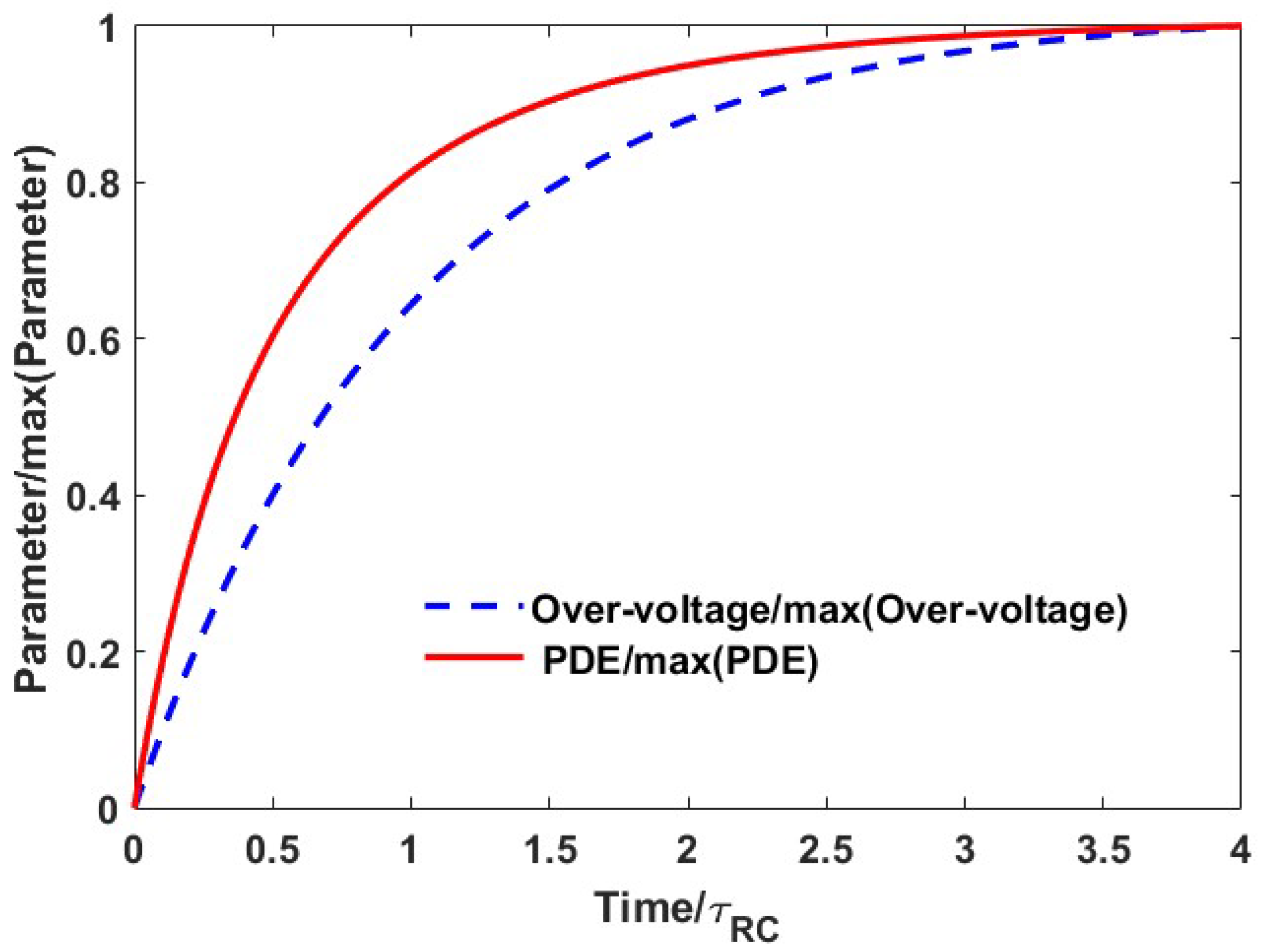
Figure 1. The recovery of the over-voltage and the photon detection efficiency determined using Equations (1) and (2).
Photonics 09 00888 g001
Figure 2. A schematic diagram showing three microcells in a representative Onsemi SiPM. The diagram also shows how these are connected the source of the bias voltage and a digital multimeter that is used to measure the bias current needed to sustain the bias voltage.
Photonics 09 00888 g002
Figure 3. System block diagram describes the experimental setup used to evaluate the ambient light performance of the SiPM. The AWG was a 25 GS/s AWG70002A, the Power Amplifier is a Fairview FMAM3269 10 MHz to 6 GHz Amplifier, which feeds a Bias Tee (Thorlabs ZFBT-4R2GW+) and the Laser Diode a ThorLabs L405P20. The LED ring includes eight UV3TZ-405-15 LEDs, and is driven by a Keithley 224 Source Meter. During some experiments, the bias voltage applied to these 405 nm LEDs was varied to control the effective ambient light level. On the receiver side, the SiPM is coupled to a ZX60-43-S+ 4 GHz Low Noise Amplifier, which feeds a Keysight MSO64 (4 GHz, 25 GS/s) oscilloscope. The polarizer, source meter, AWG and oscilloscope are computer-controlled by MATLAB®.
Photonics 09 00888 g003
Figure 4. The photon detection efficiency of a J series 30020 SiPM on an SMPTA evaluation board measured at different over-voltages compared to Equation (1).
Photonics 09 00888 g004
Figure 5. The measured current needed to sustain a bias on the SiPM at different irradiances of 405 nm light divided by the product of the over-voltage and the PDE corresponding to the over-voltage.
Photonics 09 00888 g005
Figure 6. A comparison of the measured and simulated currents needed to sustain three different over-voltages on a 30020 SiPM.
Photonics 09 00888 g006
Figure 7. A comparison of the measured and simulated irradiances needed to support three data rates as the incident ambient light irradiance increased. The x axis is the equivalent 405 nm irradiance that generates the same count rate and hence bias current as the incident ambient light.
Photonics 09 00888 g007
Figure 8. A comparison of the measured and simulated irradiances needed to support three data rates as the number of detected ambient light photons per bit time is increased.
Photonics 09 00888 g008
Figure 9. A representative microsecond of a simulation of one microcell showing the recovery of the over-voltage and PDE. In addition, these results show an example, at approximately 0.25 μs, of a photon being detected before the microcell is fully recharged.
Photonics 09 00888 g009
Figure 10. The ratio between the characteristic time obtained from the saturated current at each over-voltage to this time for an over-voltage of 3.85 V.
Photonics 09 00888 g010
Figure 11. Experimental results for 500 Mbps and 1000 Mbps compared to the results expected from Poisson Theory and these results are combined with the correction, Equation (18). The x axis is the equivalent 405 nm irradiance that generates the same count rate and hence bias current as the incident ambient light.
Photonics 09 00888 g011
Figure 12. The mean array PDE when photons are detected and the mean charge on the microcells that have detected a photons.
Photonics 09 00888 g012
Table 1. Key parameters obtained from the manufactures data sheet for a j series 30020 [26].
Parameter30020
Number of microcells14,410
Microcells active area diameter (µm)20
Fill factor (%)62
Recharge/recovery time constant (ns)15
Dark Count Rate (MHz)1.2 (@ 5 Vov)
Fast output pulse width (ns)1.4
Table 2. Simulation Parameters for a J-Series 30020 SiPM.
Parameter30020
SiPM Area (mm2)9
Number of microcells14,410
Vbreakdown (V)24.5
Vchar (V)2.03 V
Maximum Photon Detection Efficiency at 405 nm0.46
Recharge RC time constant (ns)30.8
Microcell Capacitance (fF)46
Full width at half maximum offset output pulse width (ns)1.4
Simulation time step (s)Maximum of (bit time)/20 and
0.05 ns
Publisher’s Note: MDPI stays neutral with regard to jurisdictional claims in published maps and institutional affiliations.