Article

Synchronous Clock Recovery of Photon-Counting Underwater Optical Wireless Communication Based on Deep Learning

1
College of Information Engineering, Nanchang University, Nanchang 330031, China
2
The State Key Laboratory of Transient Optics and Photonics, Xi’an Institute of Optics and Precision Mechanics, Chinese Academy of Sciences, Xi’an 710119, China
*
Author to whom correspondence should be addressed.
Photonics 2022, 9(11), 884; https://doi.org/10.3390/photonics9110884
Submission received: 27 September 2022 / Revised: 17 November 2022 / Accepted: 18 November 2022 / Published: 21 November 2022
(This article belongs to the Special Issue Advances in Visible Light Communication)

Abstract

:
In photon-counting underwater optical wireless communication (UOWC), the recovery of the time slot synchronous clock is extremely important, and it is the basis of symbol synchronization and frame synchronization. We have previously proposed a time slot synchronous clock extraction method based on single photon pulse counting, but the accuracy needs to be further improved. Deep learning is very effective for feature extraction; synchronous information is already implicit in the discrete single photon pulse signal output by single photon avalanche diode (SPAD), which is used as a communication receiver. Aiming at this characteristic, a method of time slot synchronous clock recovery for photon-counting UOWC based on deep learning is proposed in this paper. Based on the establishment of the underwater channel model and SPAD receiver model, the Monte Carlo method is used to generate discrete single photon pulse sequences carrying synchronous information, which are used as training data. Two neural network models based on regression problem and classification problem are designed to predict the phase value of the time slot synchronous clock. Experimental results show that when the average number of photons per time slot is eight, photon-counting UOWC with a data rate of 1Mbps and a bit error rate (BER) of 5.35 × 10⁻⁴ can be achieved.

1. Introduction

Nearly two-thirds of the earth’s surface is covered by the ocean, but these ocean resources remain largely unexploited. With the growing demand for resources, people’s activities in the ocean are increasing rapidly, so the demand for related underwater information transmission technology is also more urgent [1,2,3,4]. There are currently three main underwater wireless communication technologies; namely, underwater ultrasonic communication, underwater radio frequency (RF) communication and underwater optical communication. Although underwater ultrasonic communication can achieve a transmission distance of several kilometers or more, the communication rate is very low (Kbps) and cannot meet the needs of large-capacity data interaction [5,6]. As another option, underwater RF communication can provide a data transmission rate up to tens of Mbps. Its transmission distance is very limited due to severe attenuation underwater; usually, only a few meters can be transmitted [7,8]. Underwater optical wireless communication (UOWC) can provide an ultra-high data rate (Gbps), and has the characteristics of low time delay and high energy efficiency. Therefore, UOWC has become a hot research topic [9,10,11,12].
Due to the complexity of the underwater channel, the optical signal will be affected by scattering and absorption when transmitted in an underwater channel, so the optical signal is very weak while arriving at the receiving end. At present, many researchers have already realized high-speed UOWC. A 21 m UOWC with a data rate of 5.5 Gbps has been achieved in [13]. In [14], the authors realized a UOWC distance of 34.5 m with a data rate of 2.70 Gbps. Shen et al. realized a UOWC distance of over 20 m at a high data rate of up to 1.5 Gbps by using a 450 nm LD [15]. In [16], the authors proposed a UOWC system based on a convolutional neural network (CNN) demodulator and analyzed the BER performance of the system. Cui et al. experimentally demonstrated the performance of CNN-based signal decoders in UOWC systems [17]. In [18,19], the authors used a CNN combiner for feature analysis and combination, and a CNN demodulator to recover the transmitted information. Although a high sensitivity avalanche photon diode (APD) has been used as the receiver detector in the above articles and the communication rate is up to Gbps, the transmission distance is limited to tens of meters. Improving the transmission distance of UOWC from tens to hundreds of meters is a challenging task. In recent years, in order to realize long-distance UOWC, some researchers have used a single photon avalanche diode (SPAD) to detect an optical signal at the receiving end. Compared with APD, SPAD is more sensitive and can detect a single photon as the photon-counting receiver. In 2016, through simulation analysis, Wang et al. found that SPAD-based UOWC is feasible when it transmits more than 100 m in clean ocean and 300 m in pure sea water [20]. In [21], a synchronization method based on photon-counting UOWC was proposed, which achieved a communication distance of more than 100 m with a symbol error rate (SER) of 10−4. In [22], UOWC with a communication distance of 46 m based on a multi-pixel photon counter (MPPC) detector was realized. UOWC with a communication distance of 21 m and a data rate of 312.03Mbps based on MPPC was achieved in [23]. In [24], Huang et al. realized UOWC with a communication distance of 1000 m and a data rate of 10 bps based on photon-counting detectors. In [25], the author proposed a multiple light emitting diode (LED) chips parallel transmission scheme for UOWC based on SPAD, and proved that the system can significantly improve the BER performance. In [26], a real-time, high-speed UPCC system was designed and experimentally validated based on SPAD. A novel deep learning-aided signal detection scheme for an SPAD-based UOWC system was proposed in [27]. In [28], Hema et al. proposed a deep learning based signal detection system for channel estimation and increases in transmission distance. In [29], a novel fully connected deep neural network (FC-DNN)-based receiver was proposed and experimentally demonstrated in a UOWC system. All the above literatures use SPAD as the receiver detector, and all have realized relatively long-distance UOWC, but none of them have specified how to realize synchronization and recover data from the received discrete single photon pulse. Clock recovery is the basis of data recovery, including three-level synchronous clock recovery for time slots, symbols and frames. How to recover the time slot synchronous clock from the discrete random single photon pulse is the key to the demodulation of the photon-counting communication signal. In 2019, Dr. Yan et al. proposed a time slot synchronous clock recovery method based on pulse counting [30]. The time slot synchronous clock extracted by this method has low precision, especially in long-distance UOWC. When the average number of photons per bit is very small, the phase error of the extracted time slot synchronous clock is very large, resulting in a lot of errors in the recovered baseband signal.
Deep neural networks have recently achieved exciting successes in computer vision, speech recognition and natural language processing because of their powerful data learning capabilities. Deep learning models can be used not only for classification and regression, but also for feature extraction. Fast online recovery and powerful nonlinear mapping capabilities are the main advantages of deep learning methods.
In photon-counting UOWC, the synchronous clock information is implied in the discrete single photon pulse sequence output by the SPAD receiver. In view of this characteristic, we proposed a novel time slot synchronous clock recovery method based on deep learning for photon-counting UOWC. The time slot synchronous clock can be directly extracted from the received discrete single photon pulse by a trained deep neural network, so the baseband communication data can be quickly recovered. In order to verify our proposed method, a photon-counting UOWC experimental system was built.

2. System Design and Principle
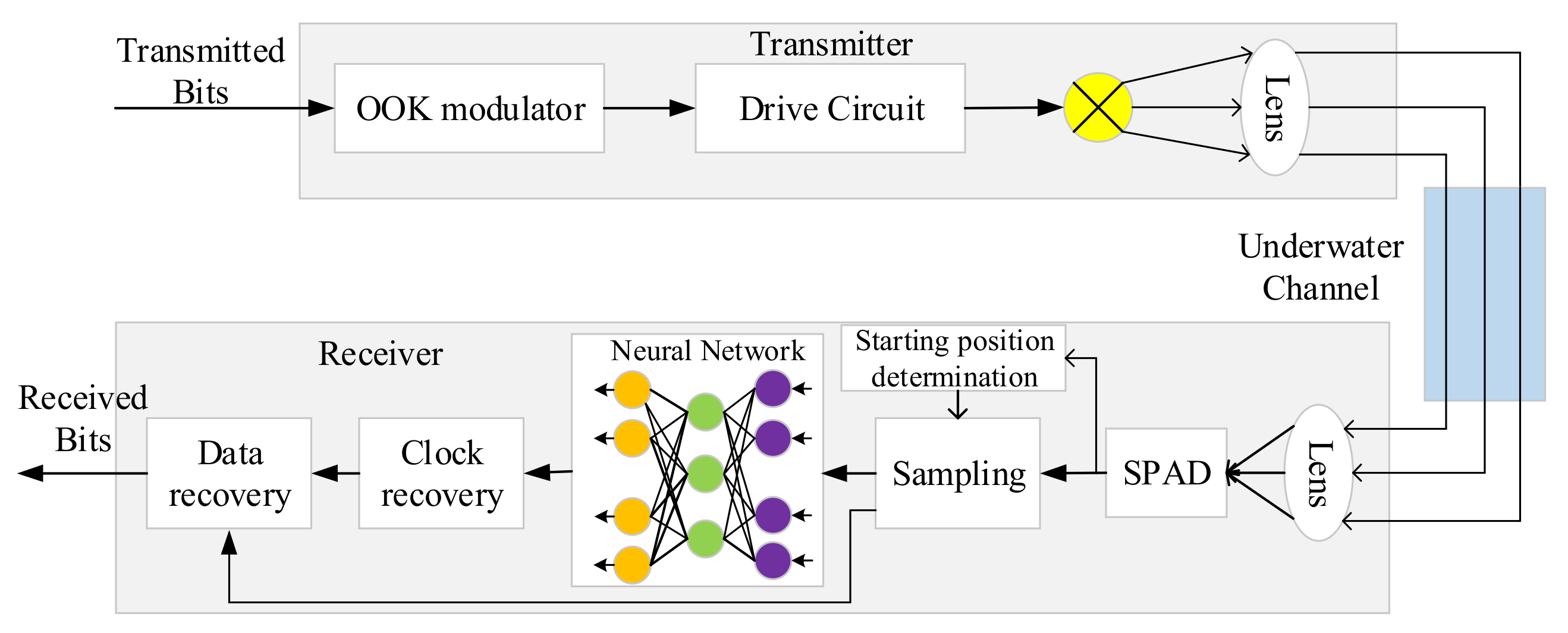
2.1. System Design

The photon-counting UOWC system based on deep learning is shown in Figure 1. The sending end performs On-Off Keying (OOK) modulation on the data to be sent and then loads it on the drive circuit, which will drive the LED to turn on and off. The light signal emitted by the LED passes through a collimating lens, which converts the originally divergent light signal into a parallel light signal, and then passes through the underwater channel. Due to the influence of absorption and scattering, the light signal is very weak while arriving at the receiving end. The receiving end uses a focusing lens to focus the optical signal into the SPAD. The discrete single photon pulse signal output by SPAD passes through a starting position determination module, and then a suitable starting sampling point is found. At the same time, the sampling module starts sampling the discrete single photon pulse output by SPAD, and the sequence after sampling is converted into binary sequence; then, the binary sequence is input into the previously trained neural network. The trained neural network extracts the feature of the binary sequence and recovers the time slot synchronous clock. Finally, the baseband signal is recovered according to the time slot synchronous clock.

2.2. Principle

2.2.1. Principle of Recovering Time Slot Synchronous Clock Based on Deep Learning

After detecting the optical signal carrying information, SPAD outputs a discrete single photon pulse signal. The phase of time slot synchronous clock is hidden in the discrete single photon pulse signal; we designed a neural network and let it learn to extract the hidden phase. As shown in Figure 2, the initial phases of the time slot synchronous clocks are set between 0 and , and the initial phases of these time slot synchronous clocks are evenly divided into M types. The underwater photon-counting wireless optical communication is simulated by the Monte Carlo method, and single photon pulse signals with different initial phases carrying the synchronization head information are obtained. These single photon pulse signals are sampled and converted into binary sequences as the data part of the training set. When single photon pulse signals with different initial phases are obtained, the phases of the corresponding time slot synchronous clocks are also different. In this paper, the phase with the smallest phase error from the ideal time slot synchronous clock phase among the M kinds of time slot synchronous clock phases uniformly classified is used as the class label of the current single photon pulse signal, and the class label is processed by one-hot encoding. After the training data are obtained through the above method, the training data are fed into the built neural network, and the weights and biases in the network are continuously trained and optimized. After the network converges, the trained network can be used to extract features from discrete single photon pulses, and then to identify and reconstruct the phase of the time slot synchronous clock from the extracted features, as shown in Figure 3.

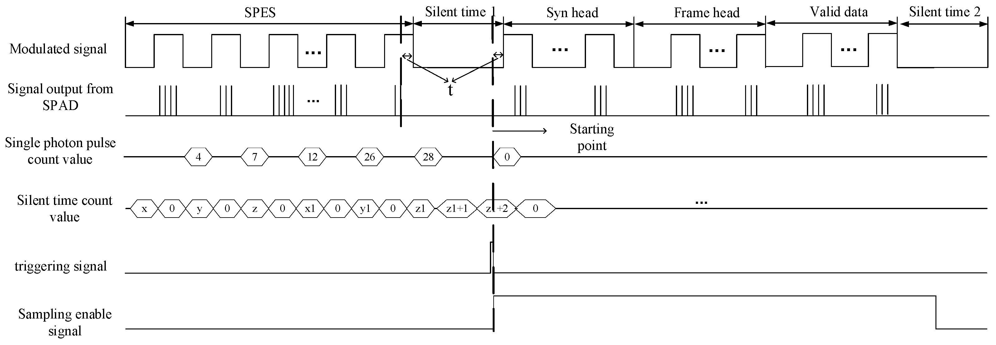
2.2.2. Frame Structure Design

In the actual photon-counting UOWC system, how to determine the starting position of a segment of data is a difficult problem. Here we design a data frame format, which can quickly find the appropriate starting position and provide the premise for data recovery. The format of the data frame is shown in Figure 4. A complete data frame consists of a series of starting position estimation sequence (SPES), silent time 1, synchronization header, frame header, valid data and silent time 2. The SPES and silent time are used to find a suitable starting position. The synchronization header sequence is a square wave signal carrying synchronization information. The function of the frame header is to mark the starting position of the valid data; the valid data are placed behind the frame header. At the end of the data frame, there is a silent time to distinguish the two different data frames.

2.2.3. Principle of Starting Position Determination

According to the data frame structure designed above, the timing diagram of how to find the starting position is shown in Figure 5. The SPAD outputs discrete random electrical pulses after detecting the light signal. We designed a counter to count the single photon pulse output by SPAD, and a timer counts the silent time of the signal output by SPAD. When the counter count value reaches a certain value and the silent time count value also reaches a certain value, we consider this moment as the starting position. At this time, pulling up the sampling enable signal starts the sampling module. The sampling module starts sampling the single photon pulse signal output by SPAD and converts the sampled sequence into binary sequence. Then, the Nfs/br sampling points in front of the binary sequence are fed into the trained neural network, so that the time slot synchronous clock phase value can be restored, and the time slot synchronous clock can be restored according to the phase value, where fs represents the sampling clock frequency, and br represents the baud rate of the modulated signal.

3. Design of Neural Network and Production of Training Data

3.1. Design of Classification and Regression Neural Network

For the deep learning method to recover the time slot synchronous clock phase value, we propose two neural network models to predict the phase value of a time slot synchronous clock. The clock phase determination network (CPD-Net) belongs to the classification network, and the clock phase reconstruction network (CPR-Net) belongs to the regression network. In both types of networks, we use a certain number of hidden layers. The benefit is to improve the accuracy of phase identification and extraction, and ultimately reduce the BER of the system. When the number of photons in a unit time slot is relatively large, a four-layer network can achieve good results. However, when the number of photons is low, there are fewer features that can be identified. In order to accurately identify features and recover the synchronous clock when the number of photons is small, we add more fully connected layers. Experiments show that when the number of photons in a unit time slot is small, the use of several layers of fully connected layers has a good effect on feature recognition, and can even reduce the overhead caused by the length of the synchronization head.

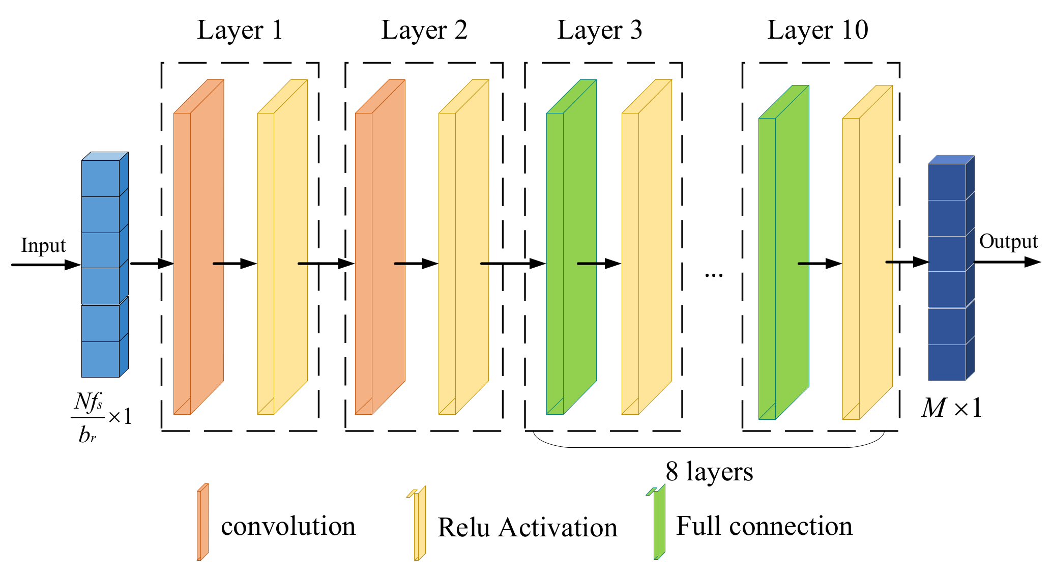
3.1.1. Structure of CPD-Net

The structure of CPD-Net is shown in Figure 6. In order to extract the phase value of the time slot synchronous clock more quickly and accurately, we designed a shallow time slot synchronous clock recognition network. This network has a small amount of calculation and high recognition accuracy. The network consists of two convolutional layers and eight fully connected layers, and each layer is followed by a ReLU activation function. The first two convolutional layers are used for phase feature extraction, the last eight fully connected layers are used for phase classification, and finally, the phase value with the highest probability is output in the output layer. To sum up, the model of CPD-Net can be expressed as:
Q ^ l = f t ( f t 1 ( f 1 ( I n ) ) )
where In represents the input data, and ft(t = 1,2,…,10) represents the mathematical operation of each layer of the network.
In general, the purpose of training a neural network is to reduce the loss function by optimizing the parameters of the network. Since CPD-Net is a typed network, the cross-entropy error is used here as the loss function, which can be expressed as:
l c p d = i = 1 M Q i * log ( P i )
where Qi is the expected output value, and Pi is the predicted probability of network output.

3.1.2. Structure of CPR-Net

Although the aforementioned CPD-Net can provide high-accuracy clock phase recognition, its phase is always a fixed category, and the precision of phase extraction is not high enough. In response to this problem, we have proposed a regression-based CPR-Net; the network structure is shown in Figure 7. The network is mainly composed of four convolutional layers and eight fully connected layers, and the ReLU activation function is used behind each layer. Four convolutional layers constitute an encoder and decoder. The first two convolutional layers are used as encoder to extract features from the discrete single photon pulse, the latter two convolutional layers are used as decoder to reconstruct the time slot synchronous clock phase value from the extracted features. Eight fully connected layers gradually reduce the dimension of the data output by the decoder. Finally, the phase prediction value is output in the output layer. In summary, the model of CPR-Net can be expressed as:
S ^ l = f n ( f n 1 ( f 1 ( U n ) ) )
where Un represents the input data and fn(n = 1,2…,12) represents the mathematical operation of each layer of the network. Since CPR-Net is a regression network, the cross entropy is no longer used as the loss function. The mean square error is used as the loss function, so its loss function can be expressed as:
l c p r = 1 n i = 1 n ( s i g i ) 2
where gi is the expected output value and si is the actual output value of the network.

3.2. Underwater Channel Model and SPAD Receiver

The relationship between the LED emission power and the average number of emitted photons can be expressed as:
P t = N t h v T ,
where Pt is the LED emission power, Nt is the average number of photons emitted by LED, h is the Planck constant, ν is the frequency of light and T is the time slot interval.
Optical signal transmission in an underwater channel will be affected by absorption and scattering. Since the absorption factor a ( λ ) and the scattering factor b ( λ ) are the main causes of channel attenuation, the accumulated total attenuation coefficient c ( λ ) = a ( λ ) + b ( λ ) in the underwater channel. According to the accumulated total attenuation coefficient, we use the Beer model to model the attenuation of underwater optical signal transmission; then, the number of photons Nr at the receiving end can be expressed as:
N r = N t e c ( λ ) L ,
where L represents the underwater communication distance.
The number of photons after SPAD optical detection can be expressed as:
λ s = μ p ( N r + N a T ) + N b T ,
where μp is the photoelectric conversion efficiency of SPAD, Na is the number of background light noise photons per unit time and Nb is the dark count of SPAD per unit time.
Generally speaking, the number of photons output by SPAD can be modeled as a Poisson statistical distribution under ideal circumstances, and the probability of detecting y photons can be expressed as:
P i d e a l ( y ) = λ s y e λ s y ! ,
When considering the dead time of SPAD, the number of photons detected by SPAD no longer obey the standard Poisson statistical distribution. At this time, the probability of detecting y photons can be given by [19]:
P ( y ) = i = 0 y λ s i ( 1 ( i + 1 ) δ ) i i ! e λ s ( 1 ( i + 1 ) δ ) i = 0 y 1 λ s i ( 1 i δ ) i i ! e λ s ( 1 i δ ) ,   if   y < y max 0 , if   y y max ,
where δ = τ T , τ is the dead time, and the maximum number of photons detected by SPAD y max = T / τ + 1 , k represents the largest integer less than k.

3.3. The Production Process of Training Data

As shown in Figure 8, according to the above underwater channel model and SPAD receiver model, we can use the Monte Carlo method to simulate the process of photon-counting UOWC to create the training data set. To prevent overfitting, we use Dropout in the network. Our training set is large enough to contain rich 01 sequences. During the test phase, we generate a large number of test single photon pulses, which also work well. This means that our network does not have the problem of overfitting.

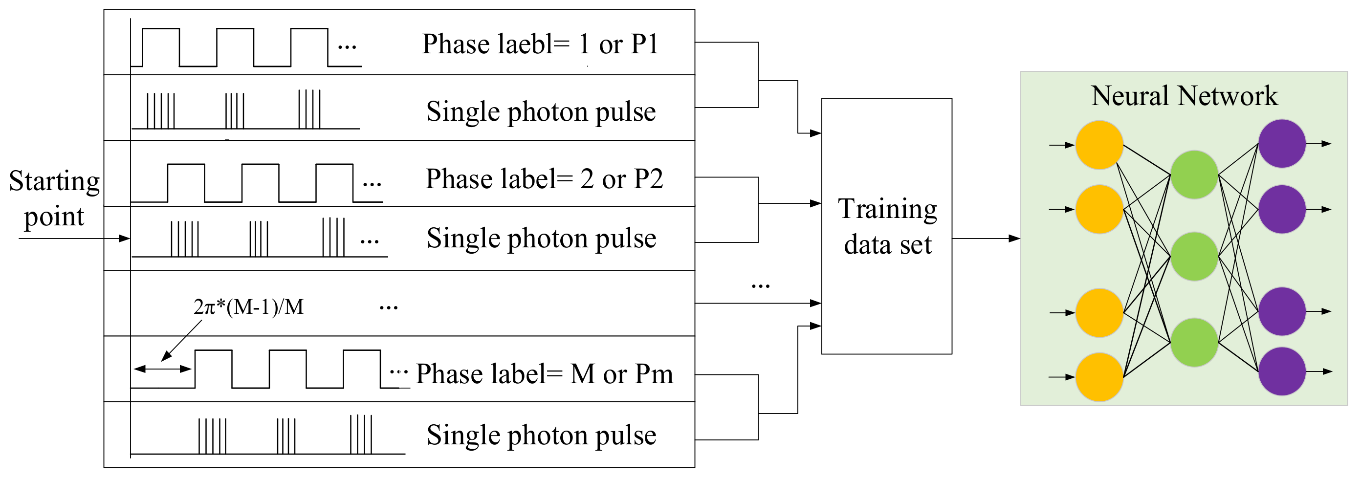
3.3.1. Training Data Production of CPD-Net

In the training data production process of CPD-Net, we stipulated that the initial phase value of the time slot synchronous clock was in the range of 0-2π, and the initial phase of the time slot synchronous clock was divided into M types evenly. The initial phase difference of two adjacent time slot synchronous clocks is 2π/M, and the M time slot synchronous clocks with different initial phases are numbered. We send synchronization header data of length N bits on the sender side, and orderly increase the initial phase of sending synchronization header data. The value of each increase is πbs/fs; the number of the corresponding time slot synchronous clock can be expressed as:
l d = f ( [ | 0 - P h | , | 2 π M - P h | , , | 2 π ( M 1 ) M - P h | ] ) ,
The function of f(x) is to find the subscript with the smallest value in the array, and Ph represents the initial phase value of the transmitted signal. For example, we divide the initial phase of the time slot synchronous clock into 20 kinds; then, every two adjacent time slot synchronous clocks are separated by π/10. At this time, the initial phase of the transmitted signal is π/40, and according to Equation (8), the time slot synchronous clock phase number corresponding to the transmitted signal is one.
When the optical signal passes through the underwater channel model and the SPAD receiver model, the single photon pulse signal output by the SPAD is sampled and binarized; the Nfs/br numbers in front of the binary sequence are taken as the data part of the training data set. At the same time, the number of the corresponding time slot synchronous clock is used as the label part of the training data set. It is very important that the label data is one-hot encoded.

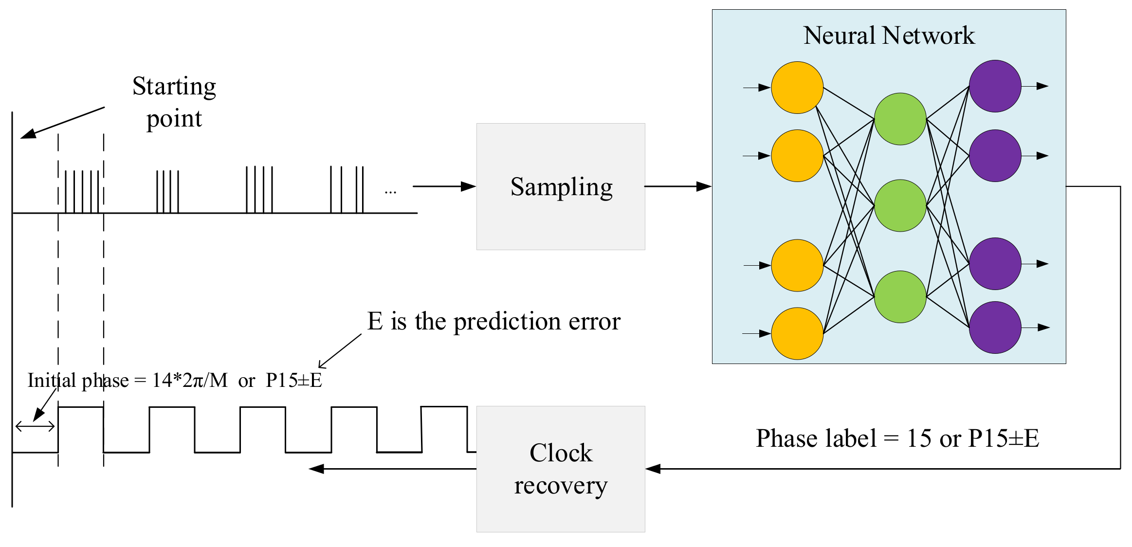
3.3.2. Training Data Production of CPR-Net

The training data production process of CPR-Net and CPD-Net are basically the same. Because CPR-Net is a network that deals with regression problems, the label in the training data of CPR-Net is no longer the phase category of the time slot synchronous clock, and the label of CPR-Net training data can be expressed as:
l c = P h ,

4. Simulation and Water Tank Experiment Results

4.1. Simulation Results

In order to verify the feasibility of the method we proposed, we conducted simulation experiments on the photon-counting UOWC system based on deep learning and gave some simulation results. In the simulation experiment, we selected two typical water qualities, Jerlov IB and Jerlov II; their attenuation coefficients are given in Table 1. In order to simulate real deep-sea communication, we did not consider the background light in the simulation process, but only considered the non-standard Poisson noise and dark counting noise in the process of SPAD detecting photons. The detailed parameters of the simulation are given in Table 2.
The results of the performance evaluation of two network models are shown in Figure 9. The training data sets used for training and testing are different. It can be seen from the figure that, whether it is in Jerlov IB or Jerlov II water quality, as the transmission distance increases, the probability of CPD-Net recognizing the correct time slot synchronous clock phase value decreases. For CPR-Net, with the increase of the transmission distance, the error between the predicted phase value output by the network and the ideal phase will increase.
As shown in Figure 10, we compared the pulse counting method and the deep learning method. It can be seen from the figure that under the same conditions, the system communication BER using the deep learning method will be lower. We can also see from the figure that the BER is lower when using regression-based CPR-Net to reconstruct the time slot synchronous clock phase value. The reason for this result is that the time slot synchronous clock phase predicted by CPR-Net is more accurate, so the system communication BER using CPR-Net recovery time slot synchronous clock is lower.

4.2. Results of Water Tank Experiment

The water tank experiment system is shown in Figure 11. At the sending end, we use a Field Programmable Gate Array (FPGA) (ALINX, AX516) to perform OOK modulation on the received data, and then drive the LED to turn on and off. A diaphragm is placed behind the LED, which is mainly used to adjust the optical power of the LED. We use a tank full of water to simulate the underwater channel; the length of the tank is about 1.5 m. Because the length of the water tank is not sufficient, in order to simulate deep-sea communication, an attenuator is placed behind the diaphragm to attenuate the light signal emitted by the LED and the tank is opaque. At the receiving end, we use another FPGA (ALTERA, DE2-115) to sample the single photon pulse signal output by the SPAD (THORLABS, SPCM 20A), and send the sampled data to the computer via Ethernet for time slot synchronous clock and data recovery.

4.2.1. Parameter Settings for Training Data Production

In order to use the trained network in our water tank experiment system, we produced a large amount of training data through the method in Chapter 3, and then used these training data to continuously train CPD-Net and CPR-Net. It is especially important that the parameters in the process of making training data are completely consistent with the parameters of the actual water tank experimental system. In order to count the background light and dark count noise in the experimental system, this section makes a statistical analysis of the noise photon pulse output by the SPAD when the LED at the sending end is off. Figure 12 gives the statistical distribution of the number of noise photons within 1000 time slots, where the time slot frequency is 1 Hz. It can be seen from the figure that the average number of noise photons in the experimental system in 1 s is only four. When the communication baud rate is 1Mbps, the number of noise photons within each bit is basically negligible, so the background light noise and dark count noise are not considered when making the training data set in this section. The detailed parameters of the water tank experimental system are given in Table 3.

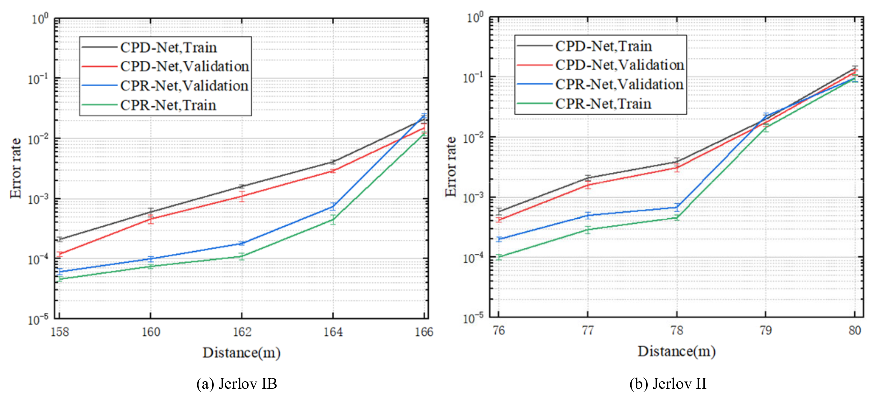
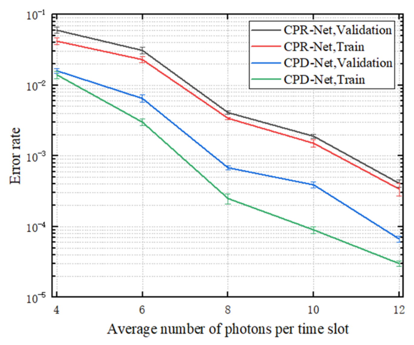
4.2.2. Analysis of Network Performance

As shown in Figure 13, we presented the training results of CPD-Net and CPR-Net when the average number of photons per time slot was different. It can be seen from the figure that as the average number of photons in each time slot increases, the probability of CPD-Net identifying the wrong time slot synchronous clock phase value gradually decreases; the error between the phase value predicted by CPR-Net and the phase value of the ideal time slot synchronous clock becomes smaller.

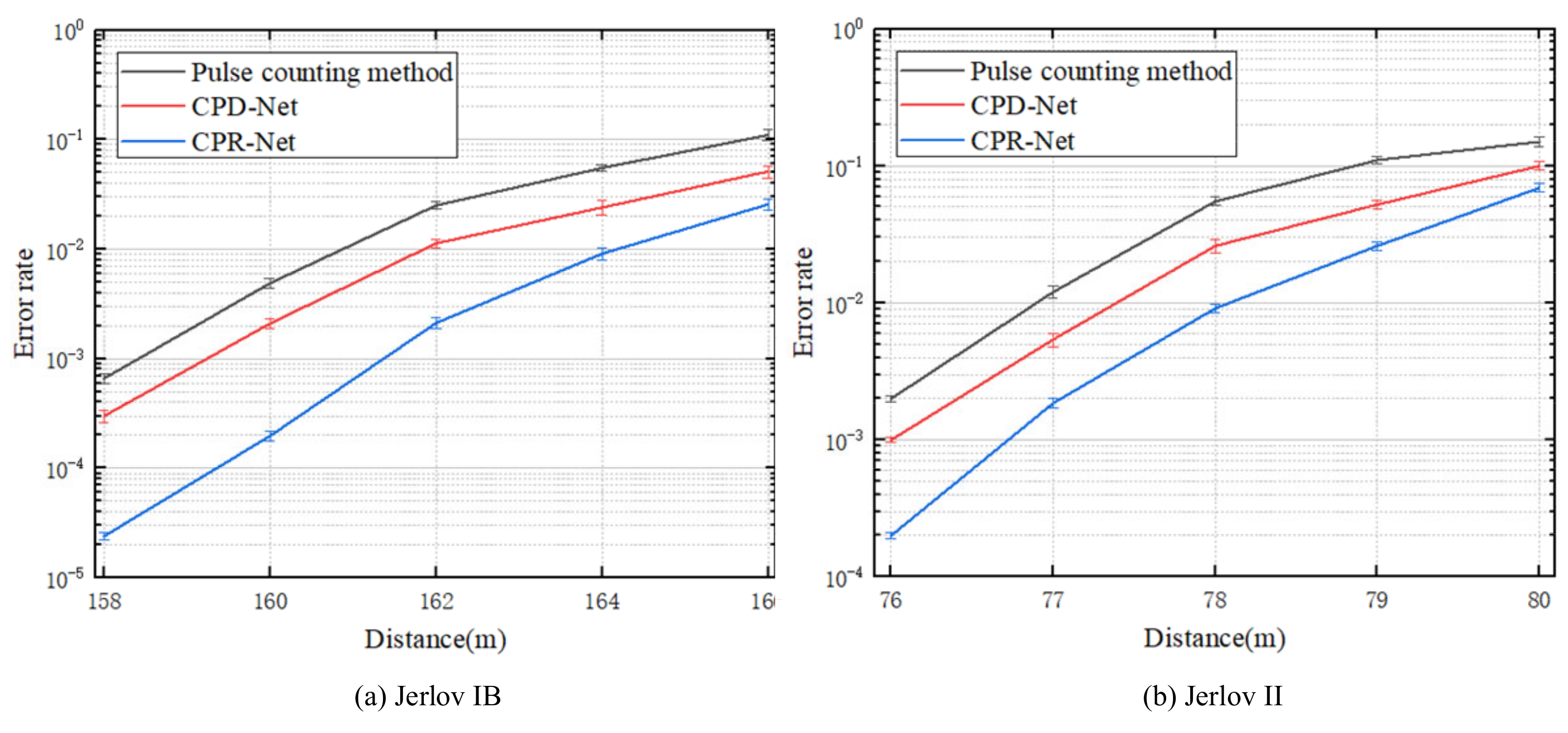
4.2.3. Analysis of Experimental Results

In order to compare the traditional pulse counting method with the deep learning method proposed by us, we adopted the deep learning method and the traditional pulse counting method to realize time slot synchronous clock and data recovery, respectively, in the water tank experimental system; the corresponding system communication BER is shown in Figure 14. It can be seen from the figure that the system communication BER using the deep learning method is lower. This phenomenon also proves that the time slot synchronous clock recovered by the deep learning method is more accurate. It is worth noting that the BER of the system using CPR-Net is lower than the BER of the system using CPD-Net, which directly shows that the method of using CPR-Net to predict the time slot synchronous clock phase value is better.

5. Conclusions

Aiming at the shortcomings of existing photon-counting UOWC time slot synchronous clock recovery methods, a time slot synchronous clock recovery scheme for photon-counting UOWC based on deep learning is proposed in this paper. By establishing an underwater channel model and SPAD receiver model, a large amount of training data is produced by using the Monte Carlo method based on these two models, and two neural network models based on the classification problem and regression problem are designed to predict the phase value of the time slot synchronous clock. When the network training is complete, we use the trained network to recover the time slot synchronous clock in the photon-counting UOWC system, and then recover the data. Both simulation and water tank experiment results show that the deep learning method we proposed is better than the existing pulse counting method and can effectively reduce the BER of the photon-counting UOWC system. Another point is that the method of using regression-based CPR-Net to reconstruct the time slot synchronous clock phase is better.

Author Contributions

Conceptualization, H.Y. and Q.Y.; methodology, M.W.; validation, H.Y., Q.Y. and M.W.; formal analysis, H.Y.; investigation, Y.W.; resources, P.L. and W.W.; data curation, H.Y. and M.W.; writing—original draft preparation, H.Y.; writing—review and editing, Q.Y.; visualization, Y.W.; supervision, P.L. and W.W.; project administration, Y.W., P.L. and W.W.; funding acquisition, Q.Y. All authors have read and agreed to the published version of the manuscript.

Funding

This research was funded by National Natural Science Foundation of China (No. 61565012), China Postdoctoral Science Foundation (No. 2015T80691), the Science and Technology Plan Project of Jiangxi Province (No. 20151BBE50092), the Funding Scheme to Outstanding Young Talents of Jiangxi Province (No. 20171BCB23007).

Data Availability Statement

The data presented in this study are available on request from the corresponding author.

Conflicts of Interest

The authors declare no conflict of interest.

References

  1. Kaushal, H.; Kaddoum, G. Underwater optical wireless communication. IEEE Access 2016, 4, 1518–1547. [Google Scholar] [CrossRef]
  2. Khalighi, M.A.; Uysal, M. Survey on free space optical communication: A communication theory perspective. IEEE Commun. Surv. Tutor. 2014, 16, 2231–2258. [Google Scholar] [CrossRef]
  3. Arnon, S. Underwater optical wireless communication network. Opt. Eng. 2010, 49, 015001. [Google Scholar] [CrossRef]
  4. Akyildiz, F.; Pompili, D.; Melodia, T. Underwater acoustic sensor networks: Research challenges. Ad Hoc Netw. 2005, 3, 257–279. [Google Scholar] [CrossRef]
  5. Sozer, E.M.; Stojanovic, M.; Proakis, J.G. Underwater acoustic networks. IEEE J. Ocean. Eng. 2000, 25, 72–83. [Google Scholar] [CrossRef]
  6. Wang, J.-M.; Lu, C.-H.; Li, S.-B.; Xu, Z.-Y. 100 m/500 Mbps underwater optical wireless communication using an NRZ-OOK modulated 520 nm laser diode. Opt. Express 2019, 27, 12171–12181. [Google Scholar] [CrossRef]
  7. Cochenour, B.; Mullen, L.; Muth, J. Temporal response of the underwater optical channel for high-bandwidth wireless laser communications. IEEE J. Ocean. Eng. 2013, 38, 730–742. [Google Scholar] [CrossRef]
  8. Xu, J.; Kong, M.W.; Lin, A.B.; Song, Y.H.; Yu, X.Y.; Qu, F.Z.; Han, J.; Deng, N. OFDM-based broadband underwater wireless optical communication system using a compact blue LED. Opt. Commun. 2016, 369, 100–105. [Google Scholar] [CrossRef]
  9. Nakamura, K.; Mizukoshi, I.; Hanawa, M. Optical wireless transmission of 405 nm, 1.45 Gbit/s optical IM/DD-OFDM signals through a 4.8 m underwater channel. Opt. Express 2015, 23, 1558–1566. [Google Scholar] [CrossRef]
  10. Oubei, H.M.; Duráan, J.R.; Janjua, B.; Wang, H.-Y.; Tsai, C.-T.; Chi, Y.-C.; Ng, T.K.; Kuo, H.-C.; He, J.-H.; Alouini, M.-S.; et al. Wireless Optical Transmission of 450 nm, 3.2 Gbit/s 16-QAM-OFDM Signals over 6.6 m Underwater Channel. In Proceedings of the Conference on Lasers and Electro-Optics, San Jose, CA, USA, 5–10 June 2016; p. SW1F.1. [Google Scholar]
  11. Xu, J.; Song, Y.; Yu, X.; Lin, A.; Kong, M.; Han, J.; Deng, N. Underwater wireless transmission of high-speed QAM-OFDM signals using a compact red-light laser. Opt. Express 2016, 24, 8097–8109. [Google Scholar] [CrossRef]
  12. Xu, J.; Lin, A.; Yu, X.; Kong, M.; Song, Y.; Qu, F.; Han, J.; Jia, W.; Deng, N. High-speed underwater wireless optical communication using a compact OFDM-modulated green laser diode. IEEE Photonics Technol. Lett. 2016, 28, 2133–2136. [Google Scholar] [CrossRef]
  13. Chen, Y.-F.; Kong, M.-W.; Ali, T.; Wang, J.-L.; Sarwar, R.; Han, J.; Guo, C.-Y.; Sun, B.; Deng, N.; Xu, J. 26 m/5.5 Gbps air-water optical wireless communication based on an OFDM-modulated 520-nm laser diode. Opt. Express 2017, 25, 14760–14765. [Google Scholar] [CrossRef]
  14. Liu, X.-Y.; Yi, S.-Y.; Zhou, X.-L.; Fang, Z.-L.; Qiu, Z.-J.; Hu, L.-G.; Cong, C.-X.; Zheng, L.-R.; Liu, R.; Tian, P.-F. 34.5 m underwater optical wireless communication with 2.70 Gbps data rate based on a green laser diode with NRZ-OOK modulation. Opt. Express 2017, 25, 27937–27947. [Google Scholar] [CrossRef]
  15. Shen, C.; Guo, Y.-J.; Oubei, H.M.; Ng, T.K.; Liu, G.-Y.; Park, K.-H.; Ho, K.-T.; Alouini, M.-S.; Ooi, B.S. 20-meter underwater wireless optical communication link with 1.5 Gbps data rate. Opt. Express 2016, 24, 25502–25509. [Google Scholar] [CrossRef]
  16. Ma, W.; Lu, H.; Chen, D.; Jin, J.; Wang, J. Orbital angular momentum underwater wireless optical communication system based on convolutional neural network. J. Opt. 2022, 24, 065701. [Google Scholar] [CrossRef]
  17. Cui, X.; Yin, X.; Chang, H.; Liao, H.; Chen, X.; Xin, X.; Wang, Y. Experimental study of machine-learning-based orbital angular momentum shift keying decoders in optical underwater channels. Opt. Commun. 2019, 452, 116–123. [Google Scholar] [CrossRef]
  18. Lu, H.; Jiang, M.; Cheng, J. Deep learning aided robust joint channel classification, channel estimation, and signal detection for underwater optical communication. IEEE Trans. Commun. 2020, 69, 2290–2303. [Google Scholar] [CrossRef]
  19. Lu, H.; Chen, W.; Jiang, M. Deep Learning Aided Misalignment-Robust Blind Receiver for Underwater Optical Communication. IEEE Wirel. Commun. Lett. 2021, 10, 1984–1988. [Google Scholar] [CrossRef]
  20. Wang, C.; Yu, H.-Y.; Zhu, Y.-J. A long distance underwater visible light communication system with single photon avalanche diode. IEEE Photonics J. 2017, 8, 7906311. [Google Scholar] [CrossRef]
  21. Hu, S.-Q.; Mi, L.; Zhou, T.-H.; Chen, W.-B. 35.88 attenuation lengths and 3.32 bits/photon underwater optical wireless communication based on photon-counting receiver with 256-PPM. Opt. Express 2018, 26, 21685–21699. [Google Scholar] [CrossRef]
  22. Shen, J.-N.; Wang, J.-L.; Yu, C.-Y.; Chen, X.; Wu, J.-Y.; Zhao, M.-M.; Qu, F.-Z.; Xu, Z.-W.; Han, J.; Xu, J. Single LED-based 46-m underwater wireless optical communication enabled by a multi-pixel photon counter with digital output. Opt. Commun. 2019, 438, 78–82. [Google Scholar] [CrossRef]
  23. Wang, J.; Yang, X.; Lv, W.; Yu, C.; Wu, J.; Zhao, M.; Qu, F.; Xu, Z.; Han, J.; Xu, J. Underwater wireless optical communication based on multi-pixel photon counter and OFDM modulation. Opt. Commun. 2019, 451, 181–185. [Google Scholar] [CrossRef]
  24. Huang, J.; Wen, G.; Dai, J.; Zhang, L.; Wang, J. Channel model and performance analysis of long-range deep sea wireless photon-counting communication. Opt. Commun. 2020, 473, 125989. [Google Scholar] [CrossRef]
  25. Wang, C.; Yu, H.Y.; Zhu, Y.J.; Wang, T.; Ji, Y.W. Multi-LED parallel transmission for long distance underwater VLC system with one SPAD receiver. Opt. Commun. 2018, 410, 889–895. [Google Scholar] [CrossRef]
  26. Huang, J.; Li, C.; Dai, J.; Shu, R.; Zhang, L.; Wang, J. Real-Time and High-Speed Underwater Photon-Counting Communication Based on SPAD and PPM Symbol Synchronization. IEEE Photonics J. 2021, 13, 7300209. [Google Scholar] [CrossRef]
  27. Jiang, R.; Sun, C.-M.; Zhang, L.; Tang, X.-K.; Wang, H.-J.; Zhang, A.-D. Deep Learning Aided Signal Detection for SPAD-Based Underwater Optical Wireless Communications. IEEE Access 2020, 8, 20363–20374. [Google Scholar] [CrossRef]
  28. Hema, R.; Sudha, S.; Ananthi, A.; Harinie, G.; Gayathri, K. Deep Learning Based Signal Detection in Underwater Wireless Optical Communication. J. Crit. Rev. 2020, 7, 1423–1436. [Google Scholar]
  29. Du, Z.; Deng, H.; Dai, Y.; Hua, Y.; Jia, B.; Qian, Z.; Xiong, J.; Lyu, W.; Zhang, Z.; Ma, D.; et al. Experimental demonstration of an OFDM-UWOC system using a direct decoding FC-DNN-based receiver. Opt. Commun. 2022, 508, 127785. [Google Scholar] [CrossRef]
  30. Yan, Q.-R.; Li, Z.-H.; Hong, Z.; Zhan, T.; Wang, Y.-H. Photon-Counting Underwater Wireless Optical Communication by Recovering Clock and Data From Discrete Single Photon Pulses. IEEE Photonics J. 2019, 11, 7905815. [Google Scholar] [CrossRef]
Figure 1. Photon-counting UOWC system based on deep learning.
Photonics 09 00884 g001
Figure 2. Principle of neural network trained to extract the hidden phase.
Photonics 09 00884 g002
Figure 3. Principle of recovering time slot synchronous clock based on deep learning.
Photonics 09 00884 g003
Figure 4. Frame structure.
Photonics 09 00884 g004
Figure 5. Timing diagram of starting position determination.
Photonics 09 00884 g005
Figure 6. The structure of CPD-Net.
Photonics 09 00884 g006
Figure 7. The structure of CPR-Net.
Photonics 09 00884 g007
Figure 8. Production process of training data.
Photonics 09 00884 g008
Figure 9. Performance evaluation of CPD-Net and CPR-Net under different water quality.
Photonics 09 00884 g009
Figure 10. The influence of different time slot synchronous clock recovery methods on system communication BER.
Photonics 09 00884 g010
Figure 11. Diagram of the water tank experimental system.
Photonics 09 00884 g011
Figure 12. Statistical distribution of the number of noise photons in 1000 time slots.
Photonics 09 00884 g012
Figure 13. The impact of the average number of photons per time slot on the performance evaluation of CPR-Net and CPD-Net.
Photonics 09 00884 g013
Figure 14. The influence of different time slot synchronous clock recovery methods on the communication BER of the water tank experimental system.
Photonics 09 00884 g014
Table 1. Jerlov IB, II water quality attenuation parameters.
Jerlov IBJerlov II
a(λ)(m−1)0.0640.087
b(λ)(m−1)0.080.216
c(λ)(m−1)0.1440.303
Table 2. Simulation parameters of photon-counting UOWC system based on deep learning.
ParametersValues
ModulationOn-Off Keying (OOK)
Baud rate (br)10 Mbps
Length of synchronization header (N)10
Phase type of synchronization clock (M)20
Sampling frequency (fs)200 MHz
Wavelength450 nm
Power of LED1 W
Max efficiency35%
Dark count rate25 Hz
Pulse width5 ns
Dead-time8 ns
Table 3. Detailed parameters of the water tank experimental system.
ParametersValues
SPAD numberSPCM 20A
ModulationOn-Off Keying (OOK)
Baud rate (br)1 Mbps
Length of synchronization header (N)40
Phase type of synchronization clock (M)50
Sampling frequency (fs)50 MHz
Wavelength450 nm
Max efficiency35%
Dark count rate25 Hz
Pulse width20 ns
Dead-time40 ns
Publisher’s Note: MDPI stays neutral with regard to jurisdictional claims in published maps and institutional affiliations.

