Communication

Toroidal Vortices of Energy in Tightly Focused Second-Order Cylindrical Vector Beams

by
Sergey S. Stafeev
1,2,*,
Elena S. Kozlova
1,2 and
Victor V. Kotlyar
1,2
1
IPSI RAS—Branch of the FSRC “Crystallography and Photonics” RAS, 443001 Samara, Russia
2
Department of Technical Cybernetics, Samara National Research University, 443086 Samara, Russia
*
Author to whom correspondence should be addressed.
Photonics 2021, 8(8), 301; https://doi.org/10.3390/photonics8080301
Submission received: 2 June 2021 / Revised: 5 July 2021 / Accepted: 25 July 2021 / Published: 28 July 2021
(This article belongs to the Special Issue Singular Optics)

Abstract

:
In this paper, we simulate the focusing of a cylindrical vector beam (CVB) of second order, using the Richards–Wolf formula. Many papers have been published on focusing CVB, but they did not report on forming of the toroidal vortices of energy (TVE) near the focus. TVE are fluxes of light energy in longitudinal planes along closed paths around some critical points at which the flux of energy is zero. In the 3D case, such longitudinal energy fluxes form a toroidal surface, and the critical points around which the energy rotates form a circle lying in the transverse plane. TVE are formed in pairs with different directions of rotation (similar to optical vortices with topological charges of different signs). We show that when light with a wavelength of 532 nm is focused by a lens with numerical aperture NA = 0.95, toroidal vortices periodically appear at a distance of about 0.45 μm (0.85 λ) from the axis (with a period along the z-axis of 0.8 μm (1.5 λ)). The vortices arise in pairs: the vortex nearest to the focal plane is twisted clockwise, and the next vortex is twisted counterclockwise. These vortices are accompanied by saddle points. At higher distances from the z-axis, this pattern of toroidal vortices is repeated, and at a distance of about 0.7 μm (1.3 λ), a region in which toroidal vortices are repeated along the z-axis is observed. When the beam is focused and limited by a narrow annular aperture, these toroidal vortices are not observed.

1. Introduction

Recently, the tight focusing of light with inhomogeneous polarization has attracted attention from researchers, due to the wide variety of focal spot shapes that can be obtained in this polarization state. For example, in previous work, compact foci have been obtained with sizes smaller than the diffraction limit [1], as well as optical needles [2], light tunnels [3,4], chains of foci [5,6], and foci with a flat apex [7,8].
Predominantly, the behavior of the intensity at the focus is investigated in the papers, for instance, in [1,2,3,4,5,6,7,8], while the behavior of the energy flux (Poynting vector) of focused beams with inhomogeneous polarization is considered much less often [9,10,11,12,13,14,15,16,17,18,19]. For example, the authors of [9] explored the tight focusing of a vector beam with a polarization that periodically changed from linear to circular along the radial or azimuthal axis. It was shown that there are points in the focus plane of these beams around which the Poynting vector rotates. The behavior of the Poynting vector in a tightly focused optical vortex with radial and azimuthal polarization was investigated in [10] and [11], respectively. The influence of the sector aperture on the energy flux at the tight focus of an azimuthally polarized beam was studied in [12], and in the same way as in [9], rotation of the Poynting vector around several points located along a certain circle was observed in the focal plane. The authors of [13] investigated the energy flux arising at the tight focus of a beam with polarization close to azimuthal, but with an additional periodically changing radial component of insignificant size (a kaleidoscope-structured vector optical beam). In [14], the self-healing properties of Bessel–Gauss beams were studied, and in particular, the transverse component of the Poynting vector in beam sections was analyzed.
It has previously been shown that in tightly focused beams with a polarization singularity, there are regions in which the direction of the Poynting vector is opposite to the direction of the beam propagation [15,16]. The existence of such regions was noted quite a long time ago in the classical work of Richards and Wolf [20], and even earlier in the study of Ignatovsky [21]. However, the regions of negative values of the Poynting vector projection on the optical axis observed by them were small. The same areas are observed in the case of the light field diffraction at the edges [22] and with total internal reflection [23,24]. However, it is possible to make such regions sufficiently large only while sharp focusing of beams with a phase or polarization singularity [15,16]. The study in [17] showed that in the Weber modes, the projection of the Poynting vector onto the optical axis takes negative values. The energy flux is the sum of two fluxes: the spin flux and the orbital energy flux [25,26]. Thus, the presence of areas in which the total energy flux is directed towards the radiation source can be explained by the fact that the spin flux directed towards the source exceeds in absolute value the orbital energy flux [27]. A negative orbital energy flux was observed in [26]. In an earlier paper [18], we found that regions of reverse energy flux arise not only in the focus plane, but also in planes close to it. It should be also noted that the reverse energy flow allows to control some types of microparticles in tasks of optical manipulation [25]. A microparticle placed in the backflow area will move towards the direction of light propagation. This phenomenon is called a tractor beam [28].
In this paper, using the Richards–Wolf formula we simulate the focusing of a cylindrical vector beam (CVB) of second order. It is shown that toroidal vortices periodically appear at a distance of about 0.45 μm from the axis (with a period along the z-axis of 0.8 μm) when the light is focused by a lens with numerical aperture NA = 0.95. These vortices arise in pairs: the nearest to the focal plane vortex rotates clockwise, while the neighboring vortex rotates counterclockwise. The vortices are also accompanied by saddle points. The pattern of toroidal vortices is repeated at further distances from the z-axis. We observe a region in which toroidal vortices are repeated along the z-axis at a distance of about 0.7 μm. These toroidal vortices are not observed when the beam is focused and limited by a narrow annular aperture.

2. Methods

Our analysis relies on the Richards–Wolf integral [20], as
U ( ρ , ψ , z ) = i f λ α min α max 0 2 π B ( θ , φ ) T ( θ ) P ( θ , φ ) × exp { i k [ ρ sin θ cos ( φ ψ ) + z cos θ ] } sin θ d θ d φ ,
where U(ρ, ψ, z) is the electrical or magnetic field in the focal spot; B(θ, φ) is the incident electrical or magnetic field (where θ is the polar angle and φ is the azimuthal angle); T(θ) is the apodization function (the apodization function is equal to T(θ) = cos1/2θ for an aplanatic lens, whereas it is equal to T(θ)  =  cos−3/2θ for a flat diffractive lens); k = 2π/λ is the wavenumber; λ is the wavelength; αmax is the maximal polar angle determined by the numerical aperture of the lens (NA  =  sinαmax); and P(θ, φ) is the polarization matrix for the electric and magnetic fields as
P ( θ , φ ) = [ 1 + cos 2 φ ( cos θ 1 ) sin φ cos φ ( cos θ 1 ) sin θ cos φ ] a ( θ , φ ) + [ sin φ cos φ ( cos θ 1 ) 1 + sin 2 φ ( cos θ 1 ) sin θ sin φ ] b ( θ , φ ) ,
where a(θ,φ) and b(θ,φ) are the polarization functions for the x- and y-components of the incident beam, respectively.
For a light field with cylindrical polarization of the mth order, the Jones vectors are
E ( θ , ϕ ) = ( a ( θ , ϕ ) b ( θ , ϕ ) ) = ( sin ( m ϕ ) cos ( m ϕ ) ) ,
for the electric field, and
H ( θ , ϕ ) = ( a ( θ , ϕ ) b ( θ , ϕ ) ) = ( cos ( m ϕ ) sin ( m ϕ ) ) ,
for the magnetic field.
In [20], it was shown that combining Equation (1) with Equations (2)–(4) gives
E x = i m + 1 [ sin m φ I 0 , m + sin ( m 2 ) φ I 2 , m 2 ] , E y = i m + 1 [ cos m φ I 0 , m + cos ( m 2 ) φ I 2 , m 2 ] , E z = 2 i m sin ( m 1 ) φ I 1 , m 1 , H x = i m + 1 [ cos m φ I 0 , m + cos ( m 2 ) φ I 2 , m 2 ] , H y = i m + 1 [ sin m φ I 0 , m sin ( m 2 ) φ I 2 , m 2 ] , H y = 2 i m cos ( m 1 ) φ I 1 , m 1 ,
where
I 0 , m = A α min α max sin θ T ( θ ) ( 1 + cos θ ) A m ( θ ) e i k z cos θ J m ( x ) d θ , I 2 , m 2 = A α min α max sin θ T ( θ ) ( 1 cos θ ) A m ( θ ) e i k z cos θ J m 2 ( x ) d θ , I 1 , m 1 = A α min α max sin 2 θ T ( θ ) A m ( θ ) e i k z cos θ J m ( x ) d θ .
The longitudinal projection of the Poynting vector S = (Sx, Sy, Sz,), Sz = Re(ExHy* − EyHx*) can be written as
S z = [ sin m φ I 0 , m + sin ( m 2 ) φ I 2 , m 2 ] × [ sin m φ I 0 , m sin ( m 2 ) φ I 2 , m 2 ] [ cos m φ I 0 , m + cos ( m 2 ) φ I 2 , m 2 ] × [ cos m φ I 0 , m + cos ( m 2 ) φ I 2 , m 2 ] .
For an angle φ = 0, this is equal to
S z = I 0 , m 2 I 2 , m 2 2 ,
We now consider the case where
α = π/2, A(θ) = δ(θ − π/2).
This corresponds to a high numerical aperture lens (NA = 1) limited by a narrow annular aperture. We have previously shown [29] that the area of energy backflow can be enhanced in this case due to enlarging of the energy backflow depth, and the width is slightly decreased.
Taking into account Equation (9), Equation (6) for I0,m and I2,m−2 can be rewritten as
I 0 , m = A T ( θ π 2 ) J m ( k ρ ) , I 2 , m 2 = A T ( θ π 2 ) J m 2 ( k ρ ) .
The longitudinal component Sz for m = 2 is equal to
S z = A T ( θ π 2 ) [ J 2 2 ( k ρ ) J 0 2 ( k ρ ) ]
The above equation shows that when the condition in Equation (9) is valid, the areas in which Sz takes on negative values do not depend on the z-coordinate. Note that the apodization function is always positive and does not affect the sign change in Equation (11). Figure 1 shows a plot of the function J22() − J02() for λ = 0.532 μm.
Figure 1 shows that the longitudinal projection of the Poynting vector can take negative values. Areas of negative values also arise periodically at further distances from the axis. Figure 1 shows a maximum possible ratio of 5:1 between the reverse energy flow and the forward energy flow in free space.
The distribution shown in Figure 1 for the case described by Equation (9) can be considered as a continuation of the study in [19], which shown that regions with negative values of the Poynting vector arise periodically for interference between four plane waves converging at a large angle. In the present case, there is interference between an infinite number of spherical waves with continuous changes in polarization instead of four plane waves. The areas containing negative values acquire an axisymmetric character and they are also periodically repeated.
Figure 2 shows the results of a simulation based on Equation (1), in which CVB acquire of second order is focused with a lens with numerical aperture NA = 0.99, limited by a narrow annular aperture with αmin = 0.9 × αmax = 0.9 × asin(NA), m = 2.
Figure 2 shows that the areas where the direction of the Poynting vector is reversed approximately coincide with similar areas in Figure 1. There are no toroidal energy vortices in this case.

3. Results

Based on the Richards–Wolf formula in (1), we then simulated the focusing of a CVB of second order (m = 2) with a wavelength of 532 nm, using a wide-aperture lens without an annular aperture. In this simulation, we used a lens with numerical aperture NA = 0.95.
Figure 3 shows the results of focusing a cylindrical second-order vector beam using a lens with numerical aperture NA = 0.95 in the region 0.5 μm < z < 3 μm, 0.3 μm < r < 1 μm.
It can be seen from Figure 3 that there are regions in the longitudinal plane YZ around which the Poynting vector rotates. This area will have the form of a circle (‘dark ring’) in the transverse XY plane. The Poynting vector is equal to zero in it. The Poynting vector will rotate around this circle in the YZ plane (or any other longitudinal plane containing the optical axis) and the surface formed by the Poynting vector trajectories in different longitudinal planes will have the form of a torus (longitudinal cross-section of which can be either a circle or an ellipse). Figure 3c schematically shows such a toroidal vortex.
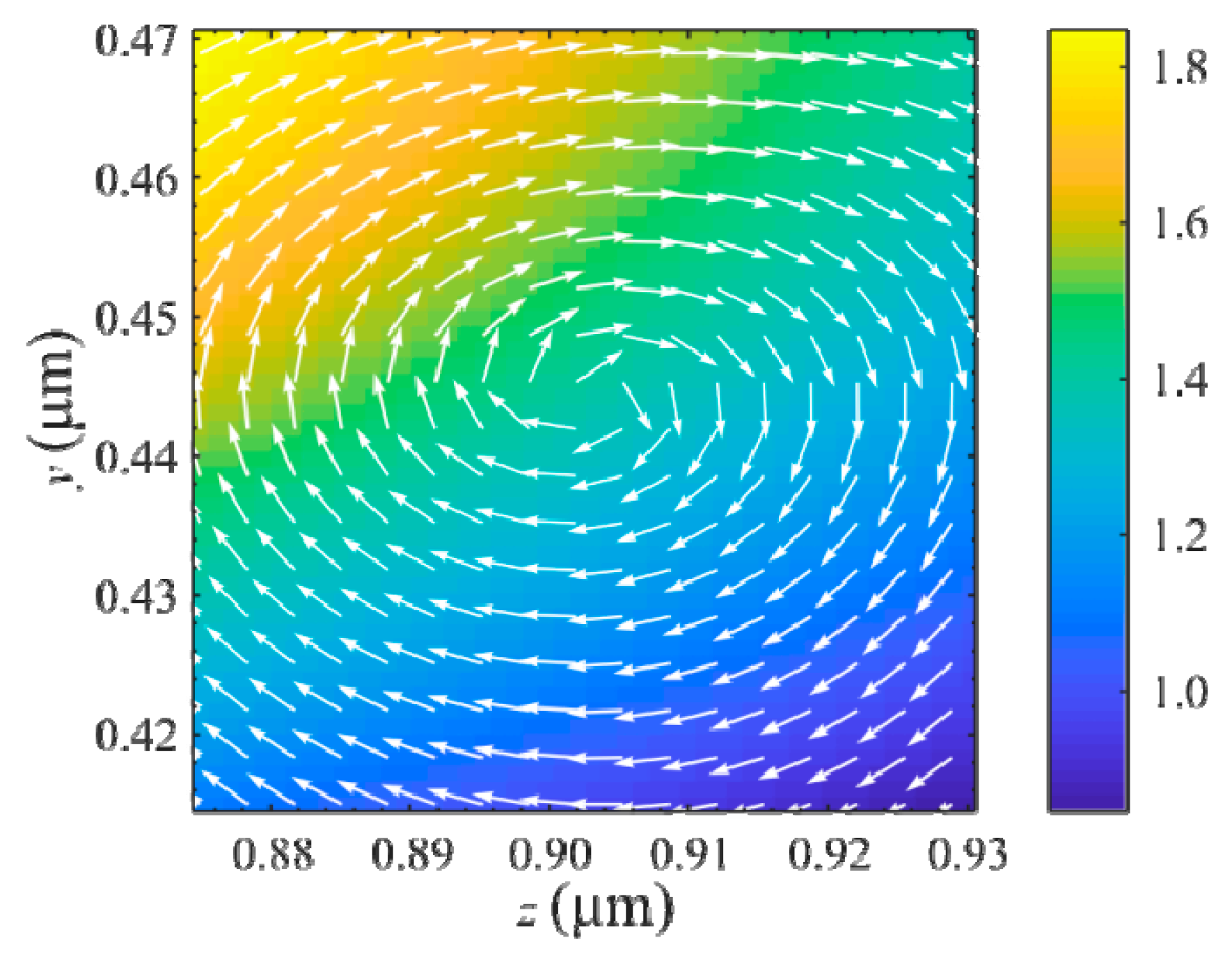
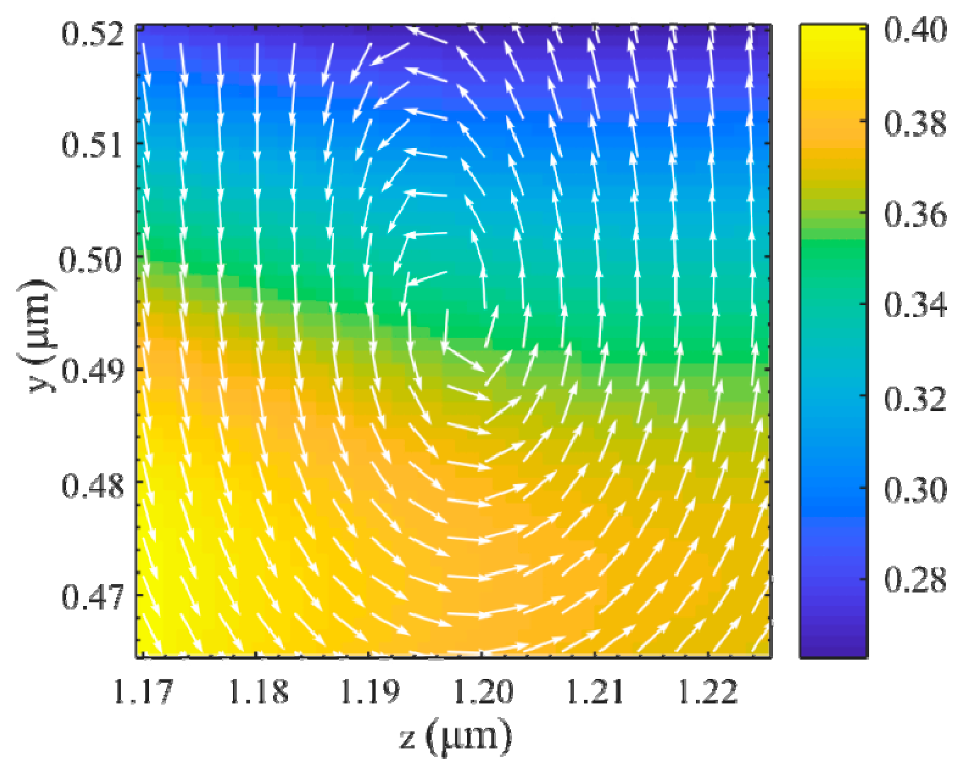
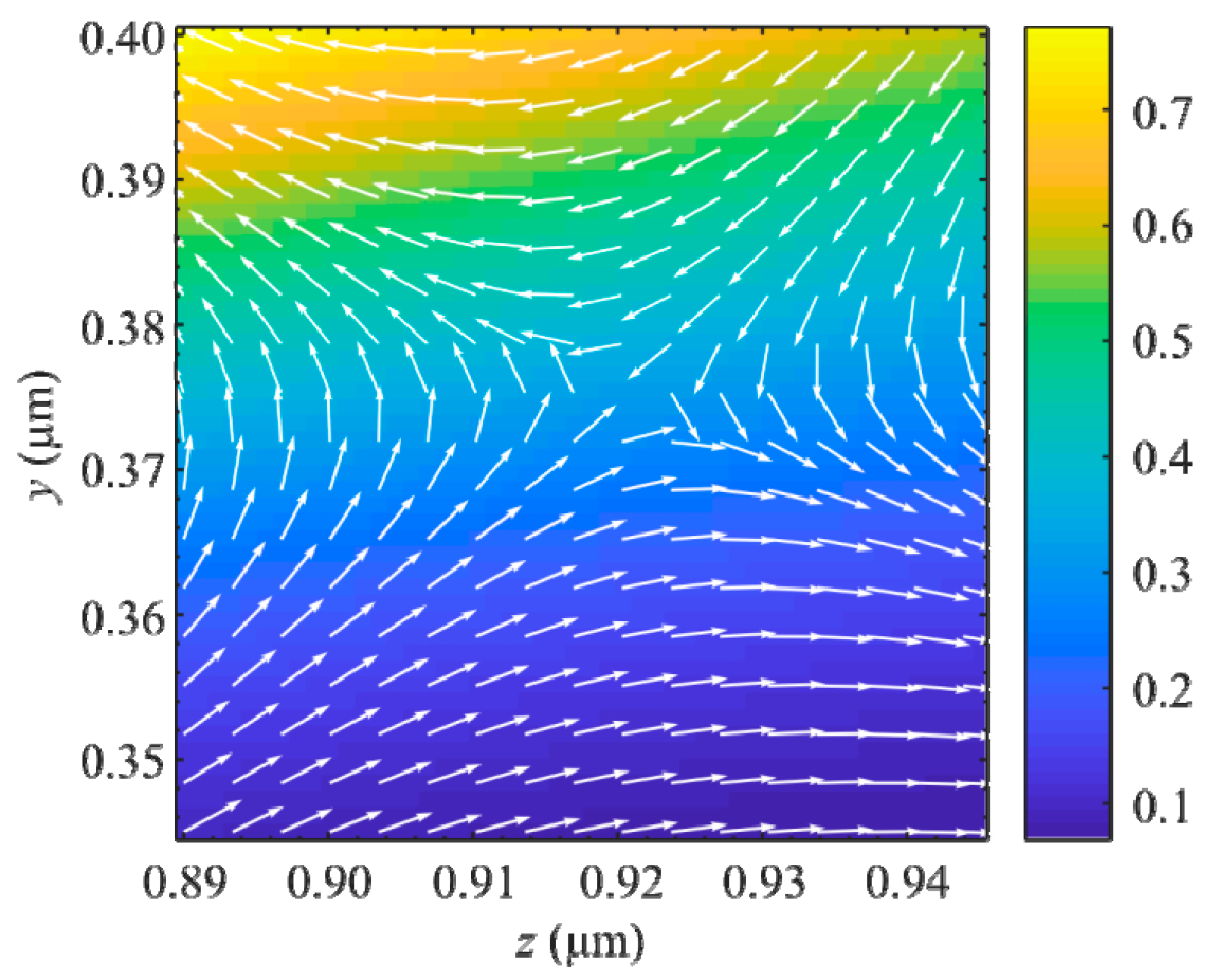
From Figure 3b, it can be seen that toroidal vortices appear periodically at a distance of approximately 0.45 μm from the axis (with a period along the z-axis of 0.8 μm). These vortices arise in pairs: the nearest to the focal plane vortex rotates clockwise (Figure 4), while the neighboring vortex rotates counterclockwise (Figure 5) and is located at a distance of approximately 0.3 μm from the clockwise vortex. The clockwise vortices are located slightly farther (about 0.05 μm) from the z-axis (r = 0) than the counterclockwise ones. The vortices are accompanied by saddle points (Figure 6), the closest of which are located at a distance of 0.4 μm from the axis. Note that the distance at which the toroidal vortices appear (the center of the vortices) approximately corresponds to the third zero of the function J22() − J02() in Figure 1. Such saddle points as well as toroidal vortices form a dark ring in the XY plane. However, in the longitudinal section YZ the Poynting vector behaves differently near such points: the vector trajectories have the form of hyperbolas (Figure 6).
At further distances from the z-axis, the pattern of toroidal vortices is repeated: a region of repeating toroidal vortices along the z-axis is also observed at a distance of approximately 0.7 μm. This distance approximately corresponds to the fifth zero of the function J22() − J02() in Figure 1.
Figure 4, Figure 5 and Figure 6 show the points of polarization singularity (V-points) at which the direction of linear polarization is undefined. The Poincaré–Hopf index is equal to η = +1 (Figure 4 and Figure 5) and η = –1 (Figure 6) [30]. In this research, we investigate V-points in the longitudinal plane, in contrast to the previous study [30], in which these points were investigated in the transverse plane.

4. Discussion

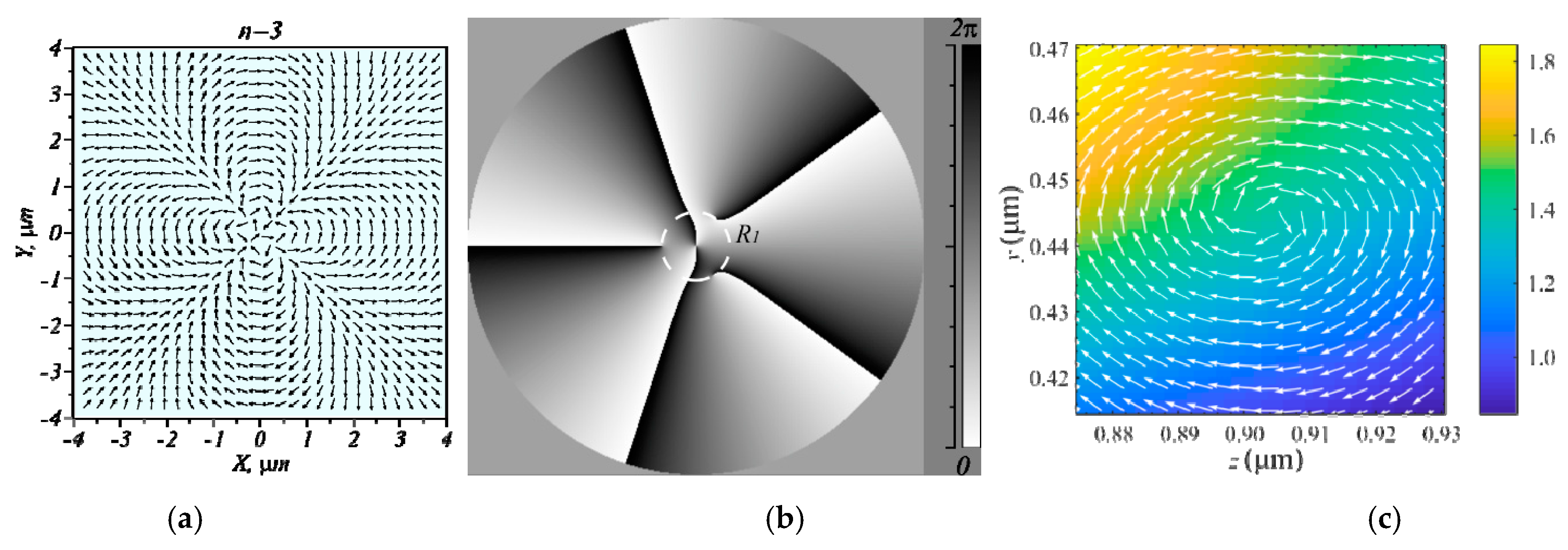
A lot of papers sharply focused on CVB are known today [1,8,31,32]. However, as a rule, these studies considered the energy distribution of the energy flux (projections of the Poynting vector) in the transverse regions near the focus and almost never considered energy flows in the longitudinal (meridional) planes. In this research, using focusing of the second-order CVB as example, we have shown that many vortices of energy or toroidal vortices of energy (TVE) can be formed near the focus in the meridional planes. TVE are flows of light energy in meridional planes along closed paths around some critical points at which the flow of energy is zero. In the 3D case, such longitudinal energy fluxes form the surface of the torus and the critical points around which the energy rotates form a circle lying in the transverse plane. TVEs are formed by pairs with different directions of rotation (similar to optical vortices with topological charges of different signs). Figure 7 shows some vortices of different nature (polarization (a), phase (b), and energy (c) vortices). The topology of such vortex flows is largely the same. The singularity index of V-points (Figure 7a) and the topological charge of the phase singularity (Figure 7b) are determined by summation of the number of the linear polarization vector complete revolutions [30] or the phase jumps by 2π [33] along a closed loop around the critical (singular) point. Therefore, the energy vortex in Figure 7c can be assigned the topological index −1 since the direction of the Poynting vector changed by 2π clockwise when going around the point of the energy flux uncertainty. The vortex energy flow index in Figure 5 is +1 since the critical point is bypassed counterclockwise.

5. Conclusions

In this paper, the focusing of second-order CVBs was numerically simulated using the Richards–Wolf formulas. The goal of the study was to determine the conditions for the formation of toroidal vortices of energy around the ‘dark rings’ (rings on which the Poynting vector is zero), not only in the focal plane but also in planes near the focus.
It was shown that when light is focused by a lens with numerical aperture NA = 0.95, toroidal vortices periodically appear at a distance of about 0.45 μm from the axis (with a period along the z-axis of 0.8 μm). These vortices arise in pairs: the one nearest to the focal plane rotates clockwise, and the neighboring one rotates counterclockwise. They are also accompanied by saddle points. At further distances from the z-axis, the pattern of toroidal vortices repeats: at a distance of about 0.7 μm, a region in which toroidal vortices repeats along the z-axis is observed. When the beam is focused and limited by a narrow annular aperture, toroidal vortices are not observed.
It should be noted that a similar effect can be observed not only for polarization vortices, but also for phase optical vortices. In particular, this holds for optical vortices with a topological charge of two and circular polarization; in addition to the beams considered above, negative values of the longitudinal projection of the Poynting vector are observed in this case on the optical axis under tight focusing conditions.

Author Contributions

Conceptualization, S.S.S. and V.V.K.; Methodology, S.S.S. and V.V.K.; Software, S.S.S. and E.S.K.; Validation, V.V.K.; Formal analysis, V.V.K.; Investigation, S.S.S., E.S.K., and V.V.K.; Resources, S.S.S.; Data curation, S.S.S.; Writing—original draft preparation, S.S.S.; Writing—review and editing, V.V.K.; Visualization, S.S.S. and E.S.K.; Supervision, V.V.K.; Project administration, V.V.K.; Funding acquisition, S.S.S. and V.V.K. All authors have read and agreed to the published version of the manuscript.

Funding

This research was funded by the Russian Science Foundation, grant number 18-19-00595 (in part of “Materials and Methods”), by the Ministry of Science and Higher Education within the State assignment FSRC “Crystallography and Photonics” RAS (in part of “Introduction” and “Conclusions”).

Institutional Review Board Statement

Not applicable.

Informed Consent Statement

Not applicable.

Data Availability Statement

Code underlying the results presented in this paper is available in https://github.com/Sergey-St/richwolf (accessed on 20 May 2021).

Conflicts of Interest

The authors declare no conflict of interest.

References

  1. Dorn, R.; Quabis, S.; Leuchs, G. Sharper focus for a radially polarized light beam. Phys. Rev. Lett. 2003, 91, 233901. [Google Scholar] [CrossRef]
  2. Chong, C.T.; Sheppard, C.; Wang, H.; Shi, L.; Lukyanchuk, B. Creation of a needle of longitudinally polarized light in vacuum using binary optics. Nat. Photonics 2008, 2, 501–505. [Google Scholar]
  3. Yu, Y.; Huang, H.; Zhou, M.; Zhan, Q. Engineering of multi-segmented light tunnel and flattop focus with designed axial lengths and gaps. Opt. Commun. 2018, 407, 398–401. [Google Scholar] [CrossRef]
  4. Zheng, C.; Su, S.; Zang, H.; Ji, Z.; Tian, Y.; Chen, S.; Mu, K.; Wei, L.; Fan, Q.; Wang, C.; et al. Characterization of the focusing performance of axial line-focused spiral zone plates. Appl. Opt. 2018, 57, 3802–3807. [Google Scholar] [CrossRef] [PubMed]
  5. Lin, J.; Chen, R.; Jin, P.; Cada, M.; Ma, Y. Generation of longitudinally polarized optical chain by 4 π focusing system. Opt. Commun. 2015, 340, 69–73. [Google Scholar] [CrossRef]
  6. Yu, Y.; Zhan, Q. Generation of uniform three-dimensional optical chain with controllable characteristics. J. Opt. 2015, 17, 105606. [Google Scholar] [CrossRef]
  7. Wang, X.; Zhu, B.; Dong, Y.; Wang, S.; Zhu, Z.; Bo, F.; Li, X. Generation of equilateral-polygon-like flat-top focus by tightly focusing radially polarized beams superposed with off-axis vortex arrays. Opt. Express 2017, 25, 26844. [Google Scholar] [CrossRef]
  8. Chen, H.; Tripathi, S.; Toussaint, K.C. Demonstration of flat-top focusing under radial polarization illumination. Opt. Lett. 2014, 39, 834. [Google Scholar] [CrossRef]
  9. Gao, X.-Z.; Pan, Y.; Zhang, G.-L.; Zhao, M.-D.; Ren, Z.-C.; Tu, C.-G.; Li, Y.-N.; Wang, H.-T. Redistributing the energy flow of tightly focused ellipticity-variant vector optical fields. Photonics Res. 2017, 5, 640. [Google Scholar] [CrossRef]
  10. Man, Z.; Bai, Z.; Zhang, S.; Li, X.; Li, J.; Ge, X.; Zhang, Y.; Fu, S. Redistributing the energy flow of a tightly focused radially polarized optical field by designing phase masks. Opt. Express 2018, 26, 23935. [Google Scholar] [CrossRef]
  11. Man, Z.; Li, X.; Zhang, S.; Bai, Z.; Lyu, Y.; Li, J.; Ge, X.; Sun, Y.; Fu, S. Manipulation of the transverse energy flow of azimuthally polarized beam in tight focusing system. Opt. Commun. 2019, 431, 174–180. [Google Scholar] [CrossRef]
  12. Jiao, X.; Liu, S.; Wang, Q.; Gan, X.; Li, P.; Zhao, J. Redistributing energy flow and polarization of a focused azimuthally polarized beam with rotationally symmetric sector-shaped obstacles. Opt. Lett. 2012, 37, 1041. [Google Scholar] [CrossRef] [PubMed]
  13. Pan, Y.; Gao, X.-Z.; Zhang, G.-L.; Li, Y.; Tu, C.; Wang, H.-T. Spin angular momentum density and transverse energy flow of tightly focused kaleidoscope-structured vector optical fields. APL Photonics 2019, 4, 096102. [Google Scholar] [CrossRef] [Green Version]
  14. Wu, G.; Wang, F.; Cai, Y. Generation and self-healing of a radially polarized Bessel-Gauss beam. Phys. Rev. A. 2014, 89, 043807. [Google Scholar] [CrossRef]
  15. Stafeev, S.S.; Kotlyar, V.V.; Nalimov, A.G.; Kozlova, E.S. The non-vortex inverse propagation of energy in a tightly focused high-order cylindrical vector beam. IEEE Photonics J. 2019, 11, 4500810. [Google Scholar] [CrossRef]
  16. Kotlyar, V.V.; Kovalev, A.A.; Nalimov, A.G. Energy density and energy flux in the focus of an optical vortex: Reverse flux of light energy. Opt. Lett. 2018, 43, 2921–2924. [Google Scholar] [CrossRef]
  17. Rondón-Ojeda, I.; Soto-Eguibar, F. Properties of the Poynting vector for invariant beams: Negative propagation in Weber beams. Wave Motion 2018, 78, 176–184. [Google Scholar] [CrossRef]
  18. Kotlyar, V.V.; Stafeev, S.S.; Kovalev, A.A. Reverse and toroidal flux of light fields with both phase and polarization higher-order singularities in the sharp focus area. Opt. Express 2019, 27, 16689–16702. [Google Scholar] [CrossRef]
  19. Li, H.; Wang, C.; Tang, M.; Li, X. Controlled negative energy flow in the focus of a radial polarized optical beam. Opt. Express 2020, 28, 18607–18615. [Google Scholar] [CrossRef]
  20. Richards, B.; Wolf, E. Electromagnetic diffraction in optical systems, II. Structure of the image field in an aplanatic system. Proc. R. Soc. A 1959, 253, 358–379. [Google Scholar]
  21. Ignatowsky, V.S. Diffraction by a lens having arbitrary opening. Trans. Opt. Inst. Petrograd 1920, 1, 4. [Google Scholar]
  22. Braunbek, W.; Laukien, G. Features of refraction by a semi-plane. Optik 1952, 9, 174–179. [Google Scholar]
  23. Wolter, H. Concerning the path of light upon total reflection. J. Opt. A Pure Appl. Opt. 2009, 11, 090401. [Google Scholar] [CrossRef]
  24. Dennis, M.R.; Götte, J.N. Beam shifts for pairs of plane waves. J. Opt. 2013, 15, 014015. [Google Scholar] [CrossRef]
  25. Bekshaev, A.Y. Subwavelength particles in an inhomogeneous light field: Optical forces associated with the spin and orbital energy flows. J. Opt. 2013, 15, 044004. [Google Scholar] [CrossRef] [Green Version]
  26. Neugebauer, M. Linear and angular momenta in tightly focused vortex segmented beams of light (Invited Paper). Chin. Opt. Lett. 2017, 15, 030003. [Google Scholar] [CrossRef] [Green Version]
  27. Stafeev, S.S.; Kotlyar, V.V. Toroidal polarization vortices in tightly focused beam with singularity. Comput. Opt. 2020, 44, 685–690. [Google Scholar] [CrossRef]
  28. Sukhov, S.; Dogariu, A. On the concept of “tractor beams”. Opt. Lett. 2010, 35, 3847–3849. [Google Scholar] [CrossRef]
  29. Stafeev, S.S.; Kotlyar, V.V. Elongation of the area of energy backflow through the use of ring apertures. Opt. Commun. 2019, 450, 67–71. [Google Scholar] [CrossRef]
  30. Freund, I. Polarization singularity indices in Gaussian laser beams. Opt. Commun. 2002, 201, 251–270. [Google Scholar] [CrossRef]
  31. Zhan, Q. Cylindrical vector beams: From mathematical concepts to applications. Adv. Opt. Photon. 2009, 1, 1–57. [Google Scholar] [CrossRef]
  32. Wang, X.; Ding, J.; Ni, W.; Guo, C.; Wang, H. Generation of arbitrary vector beams with a spatial light modulator and a common path interferometric arrangement. Opt. Lett. 2007, 32, 3549–3551. [Google Scholar] [CrossRef] [PubMed]
  33. Berry, M.V. Optical vortices evolving from helicoidal integer and fractional phase steps. J. Opt. A Pure Appl. Opt. 2004, 6, 259–268. [Google Scholar] [CrossRef]
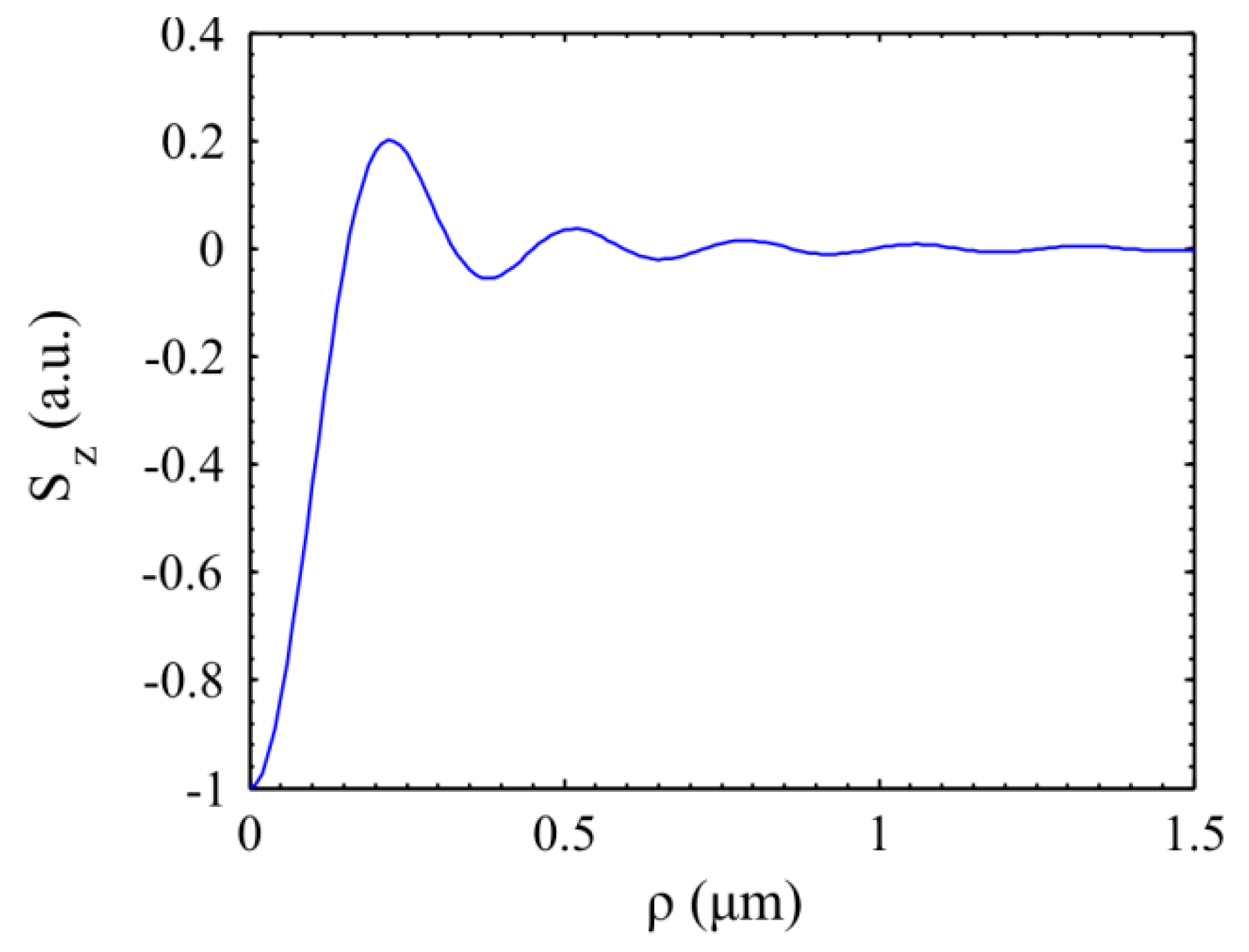
Figure 1. Plot of the function J22() − J02().
Photonics 08 00301 g001
Figure 2. Intensity and direction of the Poynting vectors in the YZ-plane of the focused CVB of second order using a lens with numerical aperture NA = 0.99, limited by a narrow annular aperture with αmin = 0.9 × αmax.
Photonics 08 00301 g002
Figure 3. (a) Intensity distribution (color) and directions of the Poynting vector (arrows) in the YZ plane and (b) positions of the points at which the Poynting vector is zero (squares-vortex with clockwise rotation, triangles-vortex with counterclockwise rotation arrows, circles-saddle points). The numbers indicate the individual areas shown in the figures below. (c) Schematic representation of a toroidal vortex of energy.
Photonics 08 00301 g003aPhotonics 08 00301 g003b
Figure 4. Intensity distribution (color) and directions of the Poynting vectors (arrows) in the region of the toroidal vortex that rotates clockwise and is nearest to the r- and z-axes (area 1 in Figure 3a).
Photonics 08 00301 g004
Figure 5. Intensity distribution (color) and directions of the Poynting vectors (arrows) in the region of the toroidal vortex that rotates counterclockwise and is nearest to the r- and z-axes (area 2 in Figure 3a).
Photonics 08 00301 g005
Figure 6. Intensity distribution (color) and direction of the Poynting vector (arrows) in the region of the saddle point nearest to the r- and z-axes (area 3 in Figure 3a).
Photonics 08 00301 g006
Figure 7. Examples of critical points (singularity points): (a) V-point at the center of the CVB field with order n = 3 (arrows show the directions of local linear polarization vectors); (b) phase (from zero to 2π) of an optical vortex with the center of a fifth-order phase singularity (topological charge is 5); and (c) the point of uncertainty of the energy flow direction in the meridional plane at the focus of the CVB with the order n = 2 (Figure 4).
Photonics 08 00301 g007
Publisher’s Note: MDPI stays neutral with regard to jurisdictional claims in published maps and institutional affiliations.