Novel Broadband Slot-Spiral Antenna for Terahertz Applications

 ,
,  ,
, 
Abstract
:1. Introduction
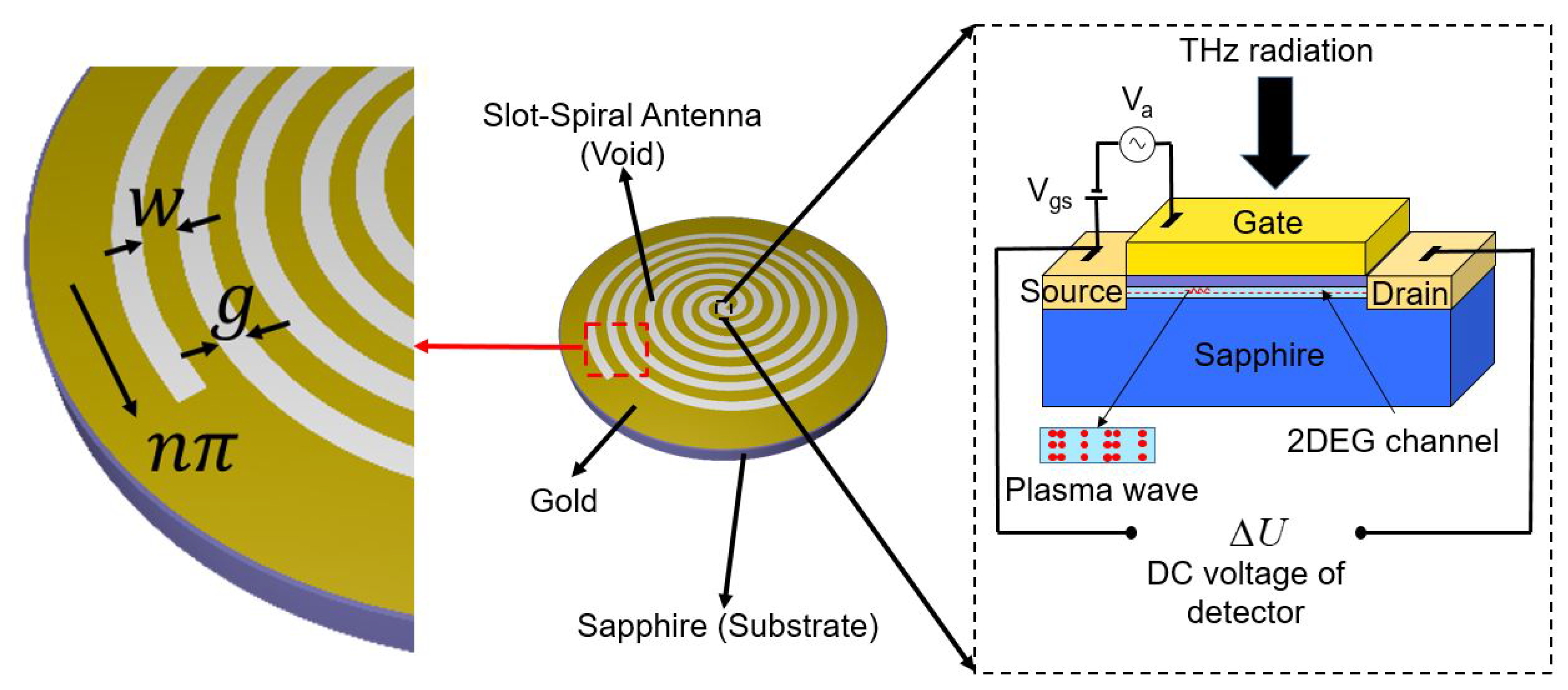
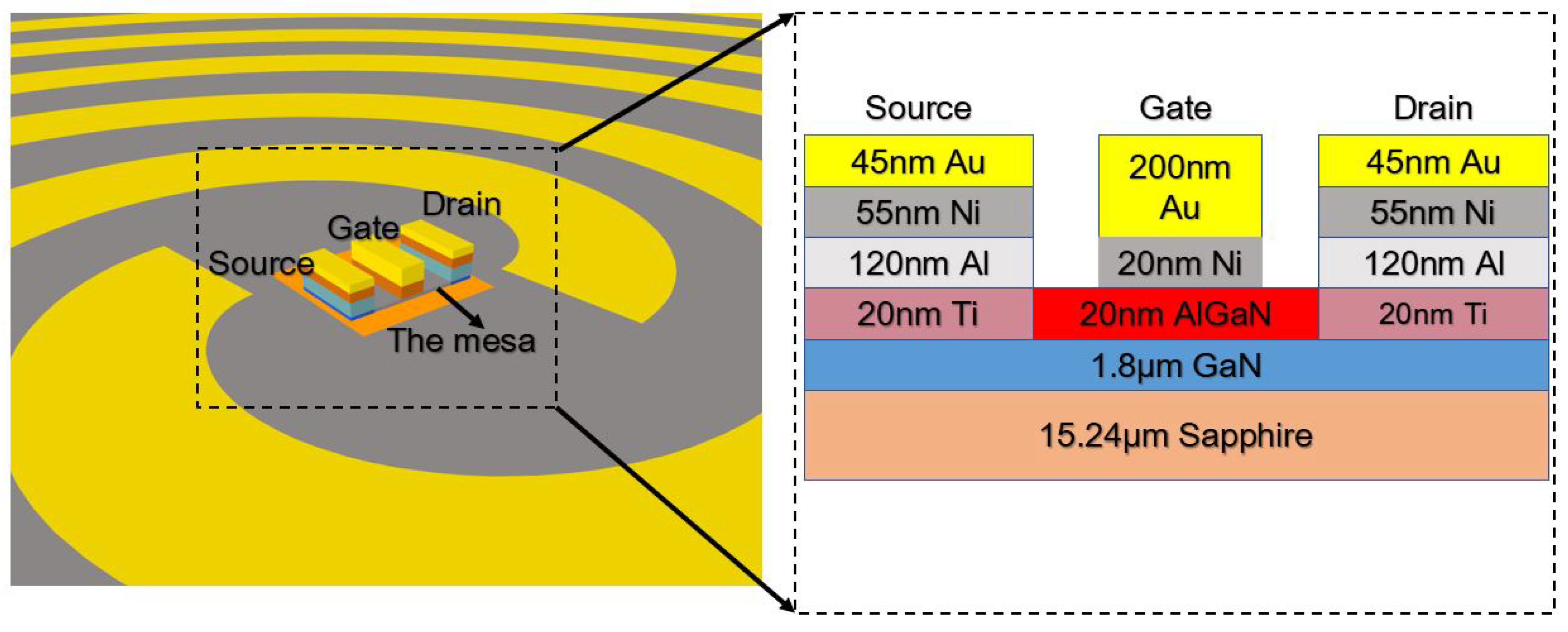
2. Detection Model
3. Terahertz Responsivity
4. Simulation Results
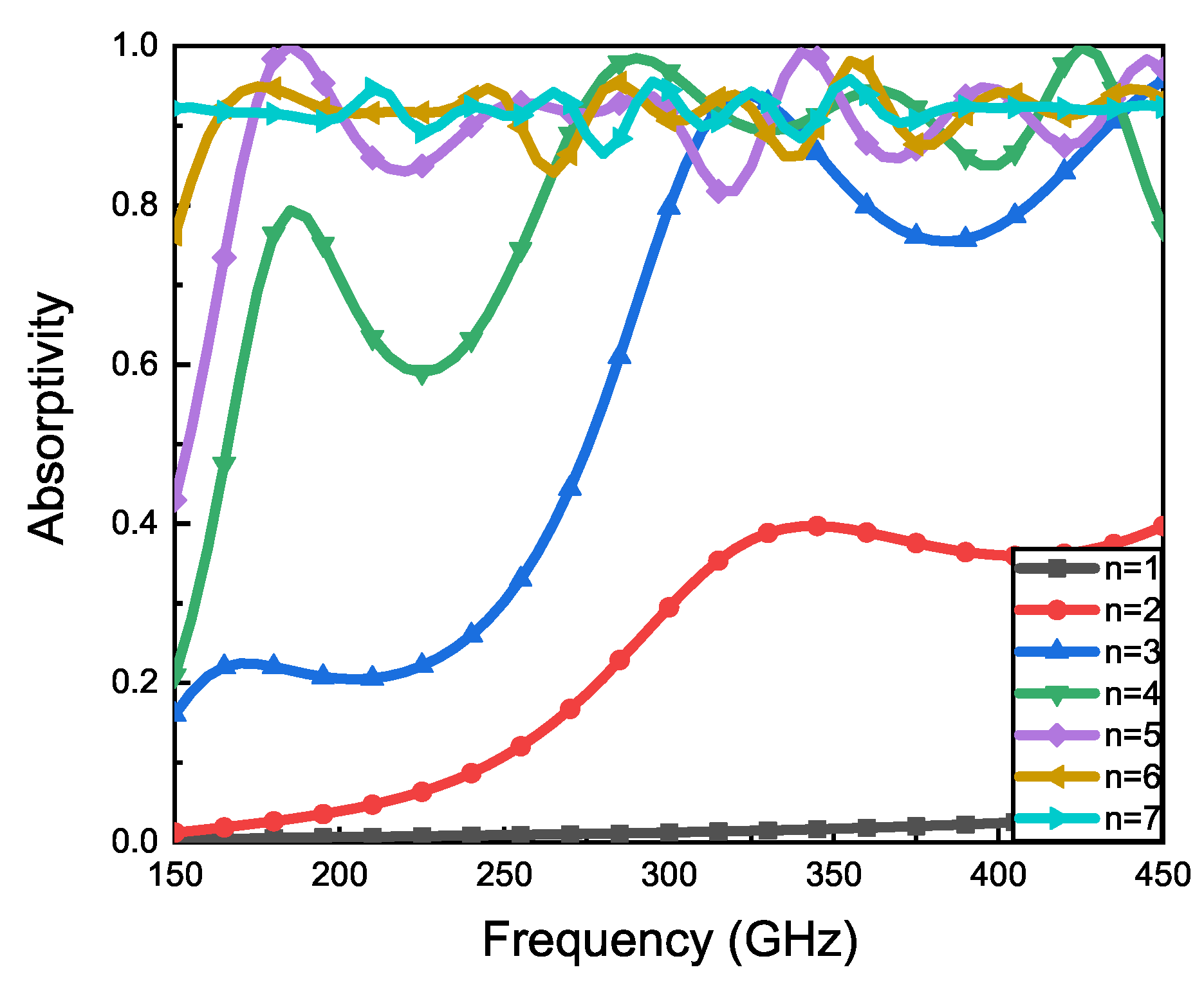
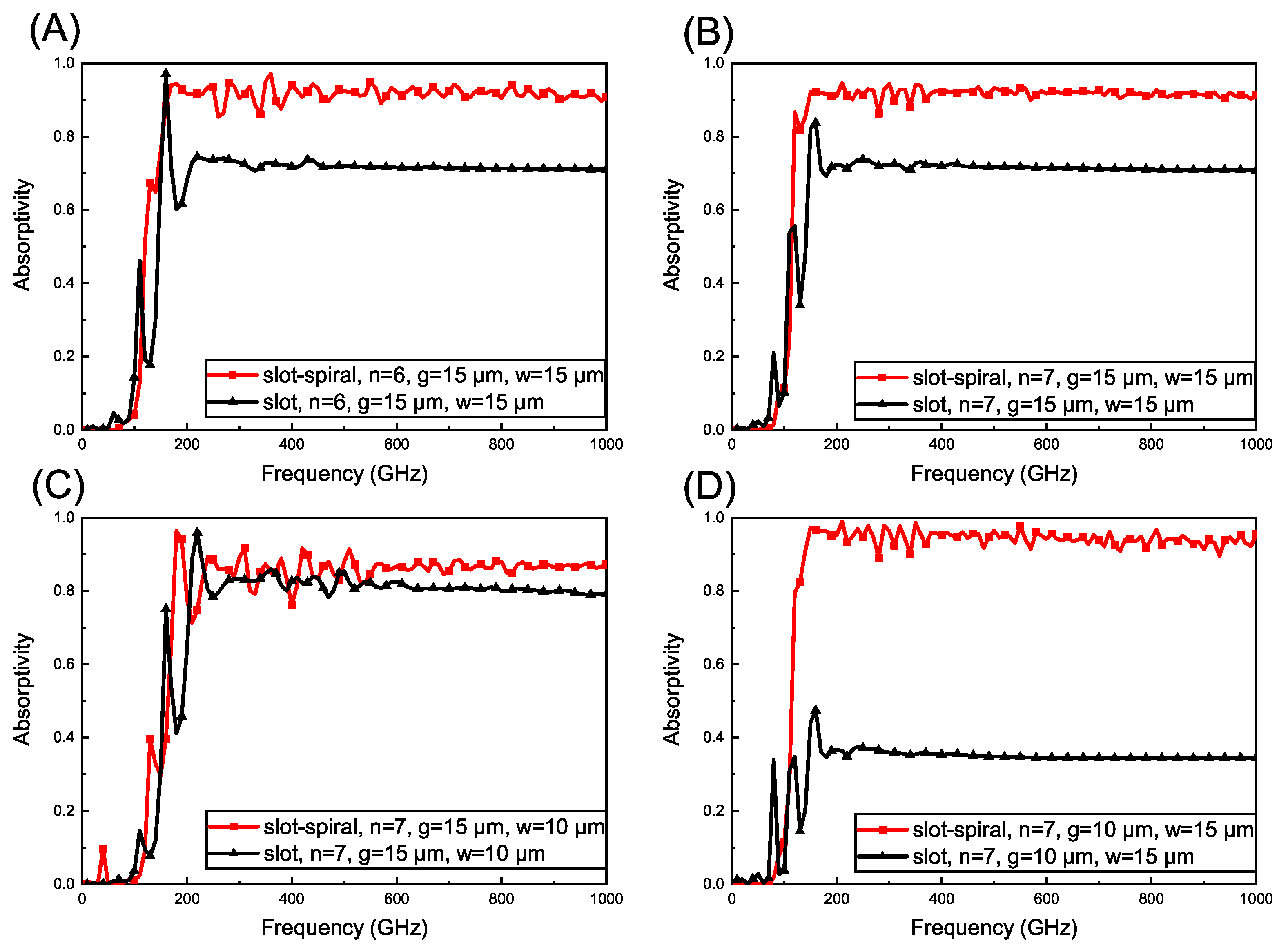
4.1. Effect of Slot-Spiral Laps
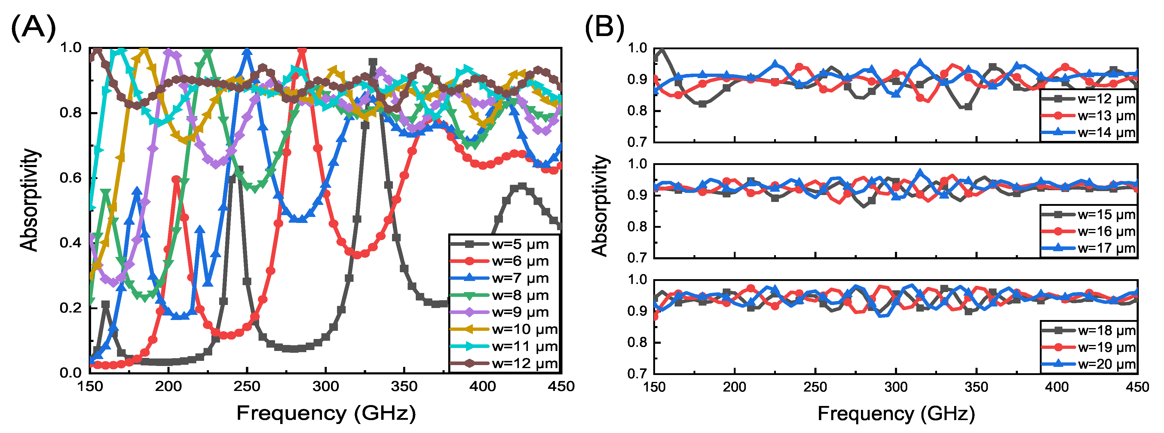
4.2. Effect of Slot-Spiral Width
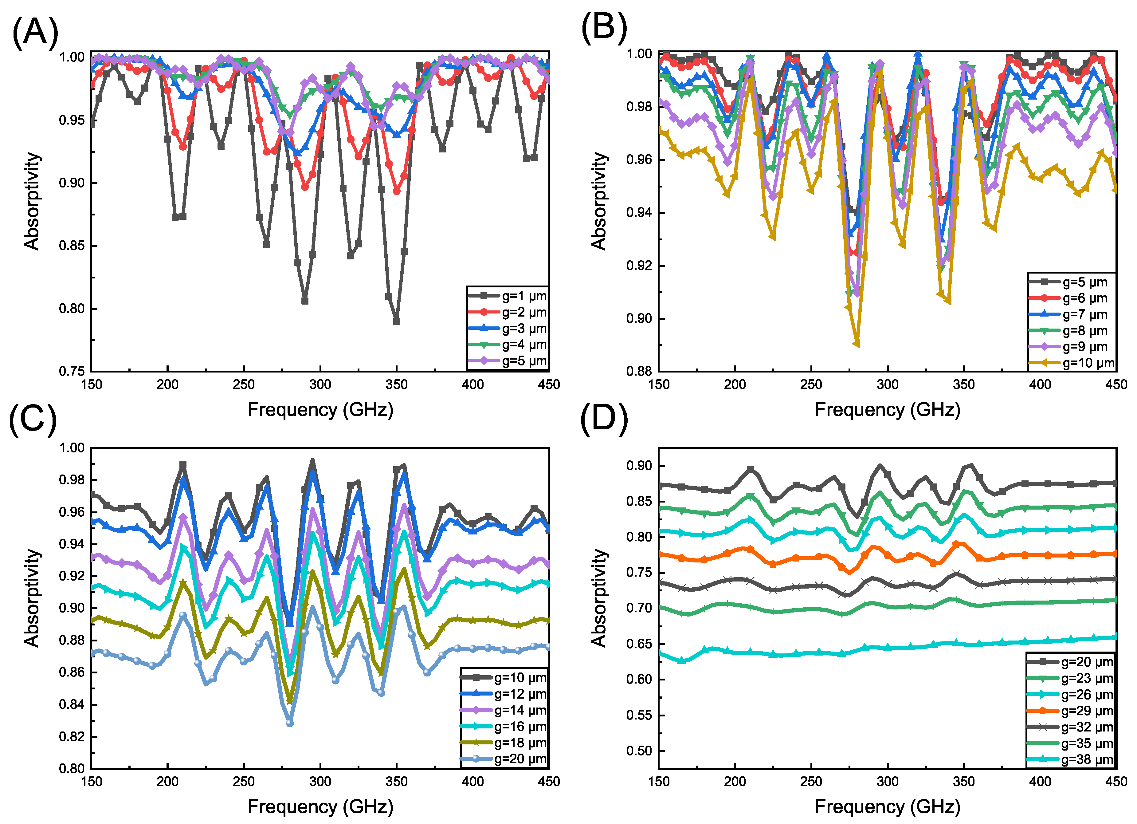
4.3. Effect of Increasing the Distance of One Rotation
5. Discussions
6. Conclusions
Author Contributions
Funding
Institutional Review Board Statement
Informed Consent Statement
Data Availability Statement
Conflicts of Interest
Abbreviations
| THz | terahertz |
| HEMT | high-electron-mobility transistor |
| 2DEG | two-dimensional electron gas |
| AC | alternating current |
| DC | direct current |
References
- Ergun, S.; Sonmez, S. Terahertz technology for military applications. J. Manag. Inf. Sci. 2015, 3, 13–16. [Google Scholar] [CrossRef]
- Xin, Z.; Chao, L. Recent development of THz technology and its application in radar and communication system. J. Microwaves 2010, 26, 1–6. [Google Scholar]
- Siegel, P.H. Terahertz technology in biology and medicine. IEEE Trans. Microw. Theory Tech. 2004, 52, 2438–2447. [Google Scholar] [CrossRef]
- Pickwell, E.; Wallace, V. Biomedical applications of terahertz technology. J. Phys. D Appl. Phys. 2006, 39, R301. [Google Scholar] [CrossRef]
- Kürner, T. Towards future THz communications systems. Terahertz Sci. Technol. 2012, 5, 11–17. [Google Scholar]
- Yang, Y.; Mandehgar, M.; Grischkowsky, D.R. Broadband THz pulse transmission through the atmosphere. IEEE Trans. Terahertz Sci. Technol. 2011, 1, 264–273. [Google Scholar] [CrossRef]
- Benford, D.J.; Amato, M.J.; Mather, J.C.; Moseley, S.H.; Leisawitz, D.T. Mission concept for the single aperture far-infrared (SAFIR) observatory. Astrophys. Space Sci. 2004, 294, 177–212. [Google Scholar] [CrossRef] [Green Version]
- Siegel, P.H. THz applications for outer and inner space. In Proceedings of the 2006 12th International Symposium on Antenna Technology and Applied Electromagnetics and Canadian Radio Sciences Conference, Montreal, QC, Canada, 17–19 July 2006; pp. 1–4. [Google Scholar]
- Dyakonov, M.; Shur, M. Shallow water analogy for a ballistic field effect transistor: New mechanism of plasma wave generation by dc current. Phys. Rev. Lett. 1993, 71, 2465. [Google Scholar] [CrossRef] [PubMed]
- Dyakonov, M.; Shur, M. Detection, mixing, and frequency multiplication of terahertz radiation by two-dimensional electronic fluid. IEEE Trans. Electron Devices 1996, 43, 380–387. [Google Scholar] [CrossRef]
- Gorbenko, I.; Kachorovskii, V.Y.; Shur, M. Terahertz plasmonic detector controlled by phase asymmetry. Opt. Express 2019, 27, 4004–4013. [Google Scholar] [CrossRef] [Green Version]
- Huang, Y.; Yu, Y.; Qin, H.; Sun, J.; Zhang, Z.; Li, X.; Huang, J.; Cai, Y. Plasmonic terahertz modulator based on a grating-coupled two-dimensional electron system. Appl. Phys. Lett. 2016, 109, 201110. [Google Scholar] [CrossRef]
- Minin, O.V.; Minin, I.V.; Meziani, Y.M.; Hisatake, S. Improvement of a point-contact detector performance using the terajet effect initiated by photonics. Opt. Eng. 2020, 60, 082005. [Google Scholar] [CrossRef]
- Öjefors, E.; Lisauskas, A.; Glaab, D.; Roskos, H.G.; Pfeiffer, U.R. Terahertz imaging detectors in CMOS technology. J. Infrared Millim. Terahertz Waves 2009, 30, 1269–1280. [Google Scholar] [CrossRef]
- Tanigawa, T.; Onishi, T.; Takigawa, S.; Otsuji, T. Enhanced responsivity in a novel AlGaN/GaN plasmon-resonant terahertz detector using gate-dipole antenna with parasitic elements. In Proceedings of the 68th Device Research Conference, Notre Dame, IN, USA, 21–23 June 2010; pp. 167–168. [Google Scholar]
- Sun, J.; Sun, Y.; Wu, D.; Cai, Y.; Qin, H.; Zhang, B. High-responsivity, low-noise, room-temperature, self-mixing terahertz detector realized using floating antennas on a GaN-based field-effect transistor. Appl. Phys. Lett. 2012, 100, 013506. [Google Scholar]
- Yu, M.; Geng, H.; Jiang, S.; Hua, T.; An, D.; Xu, W.; Chen, Z.N.; Li, J.; Wang, H.; Chen, J.; et al. Bowtie loaded meander antenna for a high-temperature superconducting terahertz detector and its characterization by the Josephson effect. Opt. Express 2020, 28, 14271–14279. [Google Scholar] [CrossRef]
- Zhang, B.W.; Yan, W.; Li, Z.F.; Bai, L.; Cywinski, G.; Yahniuk, I.; Szkudlarek, K.; Skierbiszewski, C.; Przybytek, J.; But, D.B.; et al. An effective method for antenna design in field effect transistor terahertz detectors. Int. J. Infrared Millim. Waves 2018, 37, 389–392. [Google Scholar]
- Ikamas, K.; But, D.B.; Lisauskas, A. Homodyne Spectroscopy with Broadband Terahertz Power Detector Based on 90-nm Silicon CMOS Transistor. Appl. Sci. 2021, 11, 412. [Google Scholar] [CrossRef]
- Bauer, M.; Rämer, A.; Chevtchenko, S.A.; Osipov, K.Y.; Čibiraitė, D.; Pralgauskaitė, S.; Ikamas, K.; Lisauskas, A.; Heinrich, W.; Krozer, V.; et al. A high-sensitivity AlGaN/GaN HEMT terahertz detector with integrated broadband bow-tie antenna. IEEE Trans. Terahertz Sci. Technol. 2019, 9, 430–444. [Google Scholar] [CrossRef]
- Zhang, B.; Yan, W.; Li, Z.; Bai, L.; Yang, F. Analysis of substrate effect in field effect transistor terahertz detectors. IEEE J. Sel. Top. Quantum Electron. 2016, 23, 1–7. [Google Scholar] [CrossRef]
- Liu, Z.Y.; Liu, L.Y.; Yang, J.; Wu, N.J. A CMOS fully integrated 860-GHz terahertz sensor. IEEE Trans. Terahertz Sci. Technol. 2017, 7, 455–465. [Google Scholar] [CrossRef]
- Kopyt, P.; Salski, B.; Zagrajek, P.; Obrębski, D.; Marczewski, J. Modeling of silicon-based substrates of patch antennas operating in the sub-THz range. IEEE Trans. Terahertz Sci. Technol. 2017, 7, 424–432. [Google Scholar] [CrossRef]
- Xu, L.J.; Tong, F.C.; Bai, X.; Li, Q. Design of miniaturised on-chip slot antenna for THz detector in CMOS. IET Microwaves Antennas Propag. 2018, 12, 1324–1331. [Google Scholar] [CrossRef]
- Kanazawa, Y.; Yokoyama, S.; Hiramatsu, S.; Sano, E.; Ikegami, T.; Takida, Y.; Ambalathankandy, P.; Minamide, H.; Ikebe, M. Wideband terahertz imaging pixel with a small on-chip antenna in 180 nm CMOS. Jpn. J. Appl. Phys. 2019, 58, SBBL06. [Google Scholar] [CrossRef]
- Labidi, M.; Choubani, F. Performances enhancement of metamaterial loop antenna for terahertz applications. Opt. Mater. 2018, 82, 116–122. [Google Scholar] [CrossRef]
- Hou, H.; Liu, Z.; Teng, J.; Palacios, T.; Chua, S.J. A sub-terahertz broadband detector based on a GaN high-electron-mobility transistor with nanoantennas. Appl. Phys. Express 2016, 10, 014101. [Google Scholar] [CrossRef]
- Mou, J.; Xue, Q.; Guo, D.; Lv, X. A THz detector chip with printed circular cavity as package and enhancement of antenna gain. IEEE Trans. Antennas Propag. 2016, 64, 1242–1249. [Google Scholar] [CrossRef]
- Lepeshov, S.; Gorodetsky, A.; Krasnok, A.; Rafailov, E.; Belov, P. Enhancement of terahertz photoconductive antenna operation by optical nanoantennas. Laser Photonics Rev. 2017, 11, 1600199. [Google Scholar] [CrossRef] [Green Version]
- Gric, T.; Gorodetsky, A.; Trofimov, A.; Rafailov, E. Tunable plasmonic properties and absorption enhancement in terahertz photoconductive antenna based on optimized plasmonic nanostructures. J. Infrared Millim. Terahertz Waves 2018, 39, 1028–1038. [Google Scholar] [CrossRef]
- Guo, W.; Wang, L.; Chen, X.; Liu, C.; Tang, W.; Guo, C.; Wang, J.; Lu, W. Graphene-based broadband terahertz detector integrated with a square-spiral antenna. Opt. Lett. 2018, 43, 1647–1650. [Google Scholar] [CrossRef]
- Ikamas, K.; Čibiraitė, D.; Lisauskas, A.; Bauer, M.; Krozer, V.; Roskos, H.G. Broadband terahertz power detectors based on 90-nm silicon CMOS transistors with flat responsivity up to 2.2 THz. IEEE Electron Device Lett. 2018, 39, 1413–1416. [Google Scholar] [CrossRef]
- Gou, J.; Niu, Q.; Liang, K.; Wang, J.; Jiang, Y. Frequency modulation and absorption improvement of THz micro-bolometer with micro-bridge structure by spiral-type antennas. Nanoscale Res. Lett. 2018, 13, 1–9. [Google Scholar] [CrossRef] [PubMed] [Green Version]
- Knap, W.; Deng, Y.; Rumyantsev, S.; Lü, J.Q.; Shur, M.; Saylor, C.; Brunel, L. Resonant detection of subterahertz radiation by plasma waves in a submicron field-effect transistor. Appl. Phys. Lett. 2002, 80, 3433–3435. [Google Scholar] [CrossRef]
- Knap, W.; Kachorovskii, V.; Deng, Y.; Rumyantsev, S.; Lü, J.Q.; Gaska, R.; Shur, M.; Simin, G.; Hu, X.; Khan, M.A.; et al. Nonresonant detection of terahertz radiation in field effect transistors. J. Appl. Phys. 2002, 91, 9346–9353. [Google Scholar] [CrossRef]
- Sakhno, M.; Golenkov, A.; Sizov, F. Uncooled detector challenges: Millimeter-wave and terahertz long channel field effect transistor and Schottky barrier diode detectors. J. Appl. Phys. 2013, 114, 164503. [Google Scholar] [CrossRef]
- Gou, J.; Zhang, T.; Wang, J.; Jiang, Y. Spiral antenna-coupled microbridge structures for THz application. Nanoscale Res. Lett. 2017, 12, 91. [Google Scholar] [CrossRef] [Green Version]
- Volakis, J.; Nurnberger, M.; Filipovic, D. Slot spiral antenna. IEEE Antennas Propag. Mag. 2001, 43, 15–26. [Google Scholar] [CrossRef]
- Kramer, B.A.; Lee, M.; Chen, C.C.; Volakis, J.L. Design and performance of an ultrawide-band ceramic-loaded slot spiral. IEEE Trans. Antennas Propag. 2005, 53, 2193–2199. [Google Scholar] [CrossRef]
- Dyson, J. The equiangular spiral antenna. IRE Trans. Antennas Propag. 1959, 7, 181–187. [Google Scholar] [CrossRef] [Green Version]
- Yun-Fei, S.; Jan-Dong, S.; Xiao-Yu, Z.; Hua, Q.; Bao-Shun, Z.; Dong-Min, W. Enhancement of terahertz coupling efficiency by improved antenna design in GaN/AlGaN high electron mobility transistor detectors. Chin. Phys. B 2012, 21, 108504. [Google Scholar]
- Sakhno, M.; Gumenjuk-Sichevska, J.; Sizov, F. Modeling of THz detector antenna on conductive substrate. In Proceedings of the 2016 9th International Kharkiv Symposium on Physics and Engineering of Microwaves, Millimeter and Submillimeter Waves (MSMW), Kharkiv, Ukraine, 20–24 June 2016; pp. 1–3. [Google Scholar]


Publisher’s Note: MDPI stays neutral with regard to jurisdictional claims in published maps and institutional affiliations. |
© 2021 by the authors. Licensee MDPI, Basel, Switzerland. This article is an open access article distributed under the terms and conditions of the Creative Commons Attribution (CC BY) license (https://creativecommons.org/licenses/by/4.0/).
Share and Cite
Huang, Z.; Li, Z.; Dong, H.; Yang, F.; Yan, W.; Wang, X. Novel Broadband Slot-Spiral Antenna for Terahertz Applications. Photonics 2021, 8, 123. https://doi.org/10.3390/photonics8040123
Huang Z, Li Z, Dong H, Yang F, Yan W, Wang X. Novel Broadband Slot-Spiral Antenna for Terahertz Applications. Photonics. 2021; 8(4):123. https://doi.org/10.3390/photonics8040123
Chicago/Turabian StyleHuang, Zhen, Zhaofeng Li, Hui Dong, Fuhua Yang, Wei Yan, and Xiaodong Wang. 2021. "Novel Broadband Slot-Spiral Antenna for Terahertz Applications" Photonics 8, no. 4: 123. https://doi.org/10.3390/photonics8040123
APA StyleHuang, Z., Li, Z., Dong, H., Yang, F., Yan, W., & Wang, X. (2021). Novel Broadband Slot-Spiral Antenna for Terahertz Applications. Photonics, 8(4), 123. https://doi.org/10.3390/photonics8040123