Article

Microsphere-Based Optical Frequency Comb Generator for 200 GHz Spaced WDM Data Transmission System

1
Institute of Applied Physics of the Russian Academy of Sciences, 46 Ul’yanov Street, 603950 Nizhny Novgorod, Russia
2
Lobachevsky State University of Nizhny Novgorod, 23 Gagarin Ave., 603950 Nizhny Novgorod, Russia
3
Institute of Telecommunications of the Riga Technical University, 12 Azenes street, 1048 Riga, Latvia
4
Max Planck Institute for the Science of Light, Staudtstr. 2, D-91058 Erlangen, Germany
*
Author to whom correspondence should be addressed.
Photonics 2020, 7(3), 72; https://doi.org/10.3390/photonics7030072
Submission received: 24 August 2020 / Revised: 7 September 2020 / Accepted: 9 September 2020 / Published: 11 September 2020

Abstract

:
Optical frequency comb (OFC) generators based on whispering gallery mode (WGM) microresonators have a massive potential to ensure spectral and energy efficiency in wavelength-division multiplexing (WDM) telecommunication systems. The use of silica microspheres for telecommunication applications has hardly been studied but could be promising. We propose, investigate, and optimize numerically a simple design of a silica microsphere-based OFC generator in the C-band with a free spectral range of 200 GHz and simulate its implementation to provide 4-channel 200 GHz spaced WDM data transmission system. We calculate microsphere characteristics such as WGM eigenfrequencies, dispersion, nonlinear Kerr coefficient with allowance for thermo-optical effects, and simulate OFC generation in the regime of a stable dissipative Kerr soliton. We show that by employing generated OFC lines as optical carriers for WDM data transmission, it is possible to ensure error-free data transmission with a bit error rate (BER) of 4.5 × 10⁻³⁰, providing a total of 40 Gbit/s of transmission speed on four channels.

Graphical Abstract

1. Introduction

Optical frequency combs (OFCs) generated in whispering gallery mode (WGM) microresonators, also called microcombs, are desirable for basic science and a considerable number of applications [1,2]. For example, microcombs have been used in spectroscopy [3,4], in radio-frequency photonics [5], and even in the search for exoplanets [6]. Significant activity is growing in the study of microresonator-based OFC applications in quantum optics [7]. Microcomb-based non-classical light sources are demanded in quantum information science for quantum communication [8,9,10], and can significantly advance the generation of entangled states for quantum computation [11,12].
OFCs have an enormous potential for the development of telecommunication systems, especially optical communication systems, which is the primary attention of this paper. OFCs generated in WGM resonators (WGMRs) are the ideal candidate to ensure such optical communication systems’ requirements like broadband phase coherence, high-relative frequency stability, which cannot be met with typically used expensive individual laser array solution [13]. Microcombs have been demonstrated for data transmission reaching 170.8 Gbit/s [14], 392 Gbit/s [15], 432 Gbit/s [16] and for coherent terabit communications [15,17]. Error-free data transmission with rates up to 1.44 Tbit/s for distances up to 300 km has been reported in [15,18]. Then data rate of 19.7 Tbit/s was realized on 94 comb lines modulated with PDM-16-QAM 224 Gbit/s data streams [19]. After that, two interleaved OFCs in the regime of dissipative Kerr solitons (DKS) were used to transmit a data stream with rates >50 Tbit/s on 179 individual optical carriers [17]. The application of microresonator-based OFCs in wavelength-division multiplexing passive optical networks (WDM-PONs) is a promising and cost-efficient solution. It allows using a miniature single laser source providing an entire grid of equidistant optical references instead of a traditional array of distributed feedback lasers. In telecommunications, ring resonators are typically investigated as OFC generators [15,17,20,21,22,23]. Such resonators have several advantages, including the possibility of on-chip integration, although the development cycle of such devices is quite complicated and time-consuming [24]. The use of silica microspheres for WDM-PONs has not been studied extensively but may be promising. Silica spherical microresonators can be quite simply and quickly manufactured by melting the end of standard optical fiber, followed by the formation of a microsphere under the action of surface tension. In principle, photonic devices based on silica microspheres can also be compactly packed, so their size can be comparable with miniature on-chip devices. Silica glass resonators have high Q-factors: record value is 0.8 × 10¹⁰ [25] and routinely reached values are 107–108 [26,27,28]. Silica microspheres can be produced with controllable characteristics, one of which is the free spectral range (FSR). FSR is an important characteristic because in OFC generators for WDM applications, FSR (the distance between optical carrier frequencies) should satisfy ITU-T G. 694.1 recommendation [29].
In this work, we propose and numerically study a simple design of silica microsphere-based OFC generator in the C-band with FSR of 200 GHz and simulate its implementation to ensure 4-channel 200 GHz spaced WDM data transmission system. When developing OFC generators, it should also be taken into account that the dynamics of intracavity radiation strongly depends on resonator dispersion [24,30,31]. Additionally, thermo-optical effects should also be taken into account, due to the fact, they strongly affect WGM eigenfrequencies [32]. Therefore, it is necessary to provide detailed numerical modeling of OFC formation. A silica microsphere with an FSR of 200 GHz has anomalous dispersion. In the anomalous dispersion region, a stable DKS can exist [27,33], which is investigated here. Furthermore, using the obtained numerical OFC spectrum, we chose four comb lines to provide the WDM system with optical carriers. Data transmission is realized on four frequency comb lines, with FSR equal to 200 GHz, which satisfies ITU-T recommendation G.694.1 [29] defined spectral grid for WDM systems. All four comb lines are modulated with 10 Gbit/s data stream and transmitted over 20 up to 60 km of SMF-28 fiber, therefore emulating a passive optical network (PON).

2. Methods

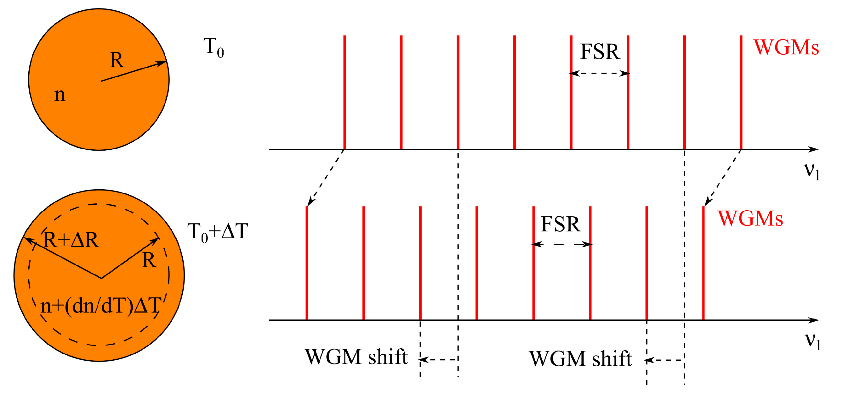
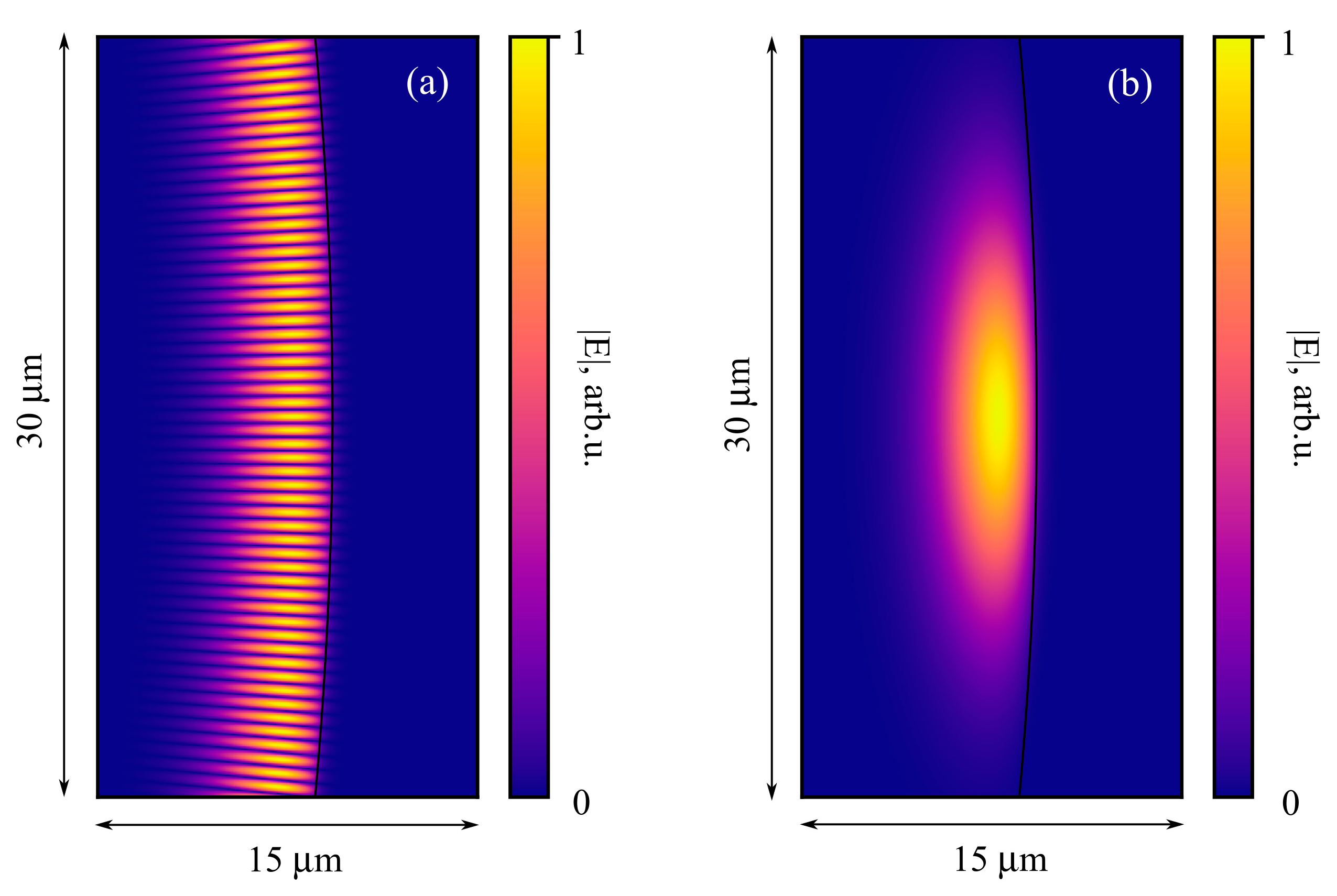
2.1. Calculation of Microresonator Characteristics

FSR is defined as c/(2πRneff), where c is the speed of light, R is the radius of a microresonator, and neff is the effective refractive index for an operating family of WGMs, so, it is essential to choose the appropriate size and take into account that not only the material but also the waveguide component gives a contribution to neff. To find an optimal size of a silica microsphere for obtaining FSR = 200 GHz, we solve the characteristic equation for different radii [34]:
n m [ ( k R ) 1 / 2 J l + 1 / 2 ( k R ) ] ( k R ) 1 / 2 J l + 1 / 2 ( k R ) = [ ( k 0 R ) 1 / 2 H l + 1 / 2 ( 1 ) ( k 0 R ) ] ( k 0 R ) 1 / 2 H l + 1 / 2 ( 1 ) ( k 0 R ) ,
where m = −1 for transverse magnetic (TM) and m = 1 for transverse electric (TE) modes; the prime denotes the derivative with respect to the argument in brackets; Jl +1/2 is the Bessel function of the order of (l + 1/2) with the azimuthal index l; Hl + 1/2(1) is the Hankel function of the 1st kind of the order of (l + 1/2); k0 = 2πν/c is the propagation constant in vacuum; ν is a frequency; k = n·k0 and n is the refractive index of the silica glass given by the Sellmeier formula [35]:
n 2 = 1 + m = 1 3 C m ω m 2 ω m 2 ω 2 ,
with constants C1 = 0.6961663, C2 = 0.4079426, C3 = 0.8974794; λ1 = 0.0684043 μm, λ2 = 0.1162414 μm, λ3 = 9.896161 μm [35], here λm = 2πc/ωm.
To solve numerically Equation (1) and find the “cold” eigenfrequencies νl, we use home-made software. We consider only a fundamental mode family corresponding to the first roots. The roots are localized by using approximation formulas for the eigenfrequencies νlapprox given, for example, in [34]:
ν l a p p r o x = c 2 π R n [ ( l + 1 / 2 ) + 1.85576 ( l + 1 / 2 ) 1 / 3 n m ( 1 n 2 1 ) 1 / 2 ] .
These values νlapprox are used as the initiators of the algorithm for searching the roots of Equation (1) by the modified Powell method [36]. The iterative algorithm is implemented with allowance for silica glass dispersion given by Equation (2).
After finding eigenfrequencies, we calculate the second-order dispersion [30]:
β 2 = 1 4 π 2 R 2 Δ ( Δ ν l ) ( Δ ν l ) 3 ,
where
Δ ν l = ν l + 1 ν l 1 2 ; Δ ( Δ ν l ) = ν l + 1 2 ν l + ν l 1 .
FSR is calculated as the difference between two neighboring eigenfrequencies near 193.1 THz.
The nonlinear Kerr coefficients γ are also estimated [33]:
γ = 2 π n 2 λ 2 π R V e f f 2 π n 2 λ 2 π R 3.4 π 3 / 2 ( λ 2 π n ) 3 l 11 / 6 .
Expressions for fields corresponding to eigenmodes are very cumbersome, therefore they are not written here but can be found in [34].
We also estimate the contribution of thermo-optical effects on eigenfrequencies and FSR using the approach developed and applied previously for tellurite glass microspheres [37]. This approach is based on the numerical simulation of steady-state temperature distribution within the heat equation framework by the finite-element method with the COMSOL software [37]. In the model, the heat source is set near the microsphere surface in the equatorial area and originates due to partially dissipated pump energy. The volume of the heat source is equal to the effective WGM volume at the pump frequency. We use the boundary conditions “external natural convection” implemented in COMSOL. After finding the steady-state temperature field (an increase in temperature by ΔT), we estimate a shift of eigenfrequencies (WGM shift). This shift with temperature growth occurs due to both, the dependence of the refractive index on temperature ‘dn/dT’ and the increase in a radius by ΔR due to the thermal expansion (see Figure 1).

2.2. Simulation of OFC Generation

The OFC generation in a single family of fundamental modes is modeled numerically in the framework of the Lugiato–Lefever equation [1,35]:
t R E ( t , τ ) t = [ 2 π i R k 2 β k k ! ( i T ) k + 2 π i R γ 0 R ( s ) | E ( t , τ s ) | 2 d s α i δ p ] E + θ E p ,
where E(t, τ) is an electric field inside the resonator; T and t = NR·tR are the fast and slow times; NR is the number of a microresonator roundtrip; tR = 2πRneff/c is the roundtrip time; δp is the phase detuning of the continuous wave (CW) pump field Ep from the nearest resonance; θ is the coupling coefficient; βk = dkβ/dω taken at the pump frequency ω0 (we set βk = 0 for k ≥ 4); β(ω) = neff·k0 is the propagation constant; γ0 is the nonlinear Kerr coefficient at ω0; α = (2π)2R/(p) is the loss coefficient including intrinsic and coupling losses; and λp is a pump wavelength. The response function is approximated by
R ( t ) = ( 1 f R ) δ ( t ) + f R h R ( t ) ,
where δ(t) is the delta function; fR = 0.18 is the fractional contribution of the delayed Raman response, and
h R ( t ) = ( τ 1 2 + τ 2 2 ) τ 1 exp ( t / τ 2 ) sin ( t / τ 1 ) ,
with constants τ1 = 12.2 fs and τ2 = 32 fs [35].
We use a home-made software based on the split-step Fourier method [35] to simulate OFC generation numerically in the frame of Equation (7). We previously simulated DKS generation with similar software without the Raman nonlinearity [38,39]. Although here, a more advanced version of the numerical code with allowance for the Raman nonlinearity is used.

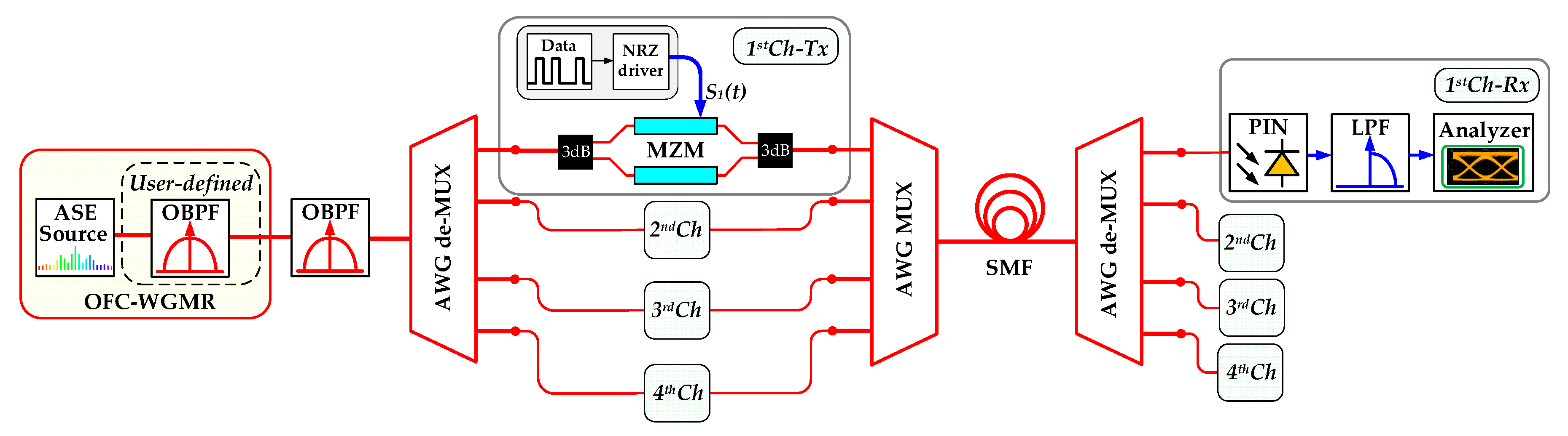
2.3. Simulation of Silica Microsphere OFC Generator-Based 4-Channel 200 GHz Spaced IM/DD WDM-PON Transmission System

The purpose of our research model was to simulate the 4-channel 200 GHz spaced intensity modulation direct detection (IM/DD) WDM-PON data transmission system by the implementation of designed silica microsphere-based OFC generator as a portable light source. We evaluate the performance of such a communication system according to next-generation PON (NG-PON2) requirements for specified valid optical link distances of up to 60 km [40]. Therefore, we used “VPI Photonics Design Suite” software for the simulation of a 4-channel 10 Gbit/s per channel non-return-to-zero on-off keying (NRZ-OOK) modulated WDM-PON optical transmission system to show the implementation of an microsphere-based OFC generator providing a spectral and energy-efficient fiber optical telecommunication system solution.
To achieve high precision of the measured results, it is crucial to provide the pseudo-random bit sequence (PRBS) with sufficient length, defined in VPI simulation scheme by using “VPI photonics design suite” simulation program modified built-in Wichman–Hill–Generator. Architecture and further simulation results of the above-described NRZ-OOK fiber optical communication system are presented in Section 3.3 of this article.

3. Results

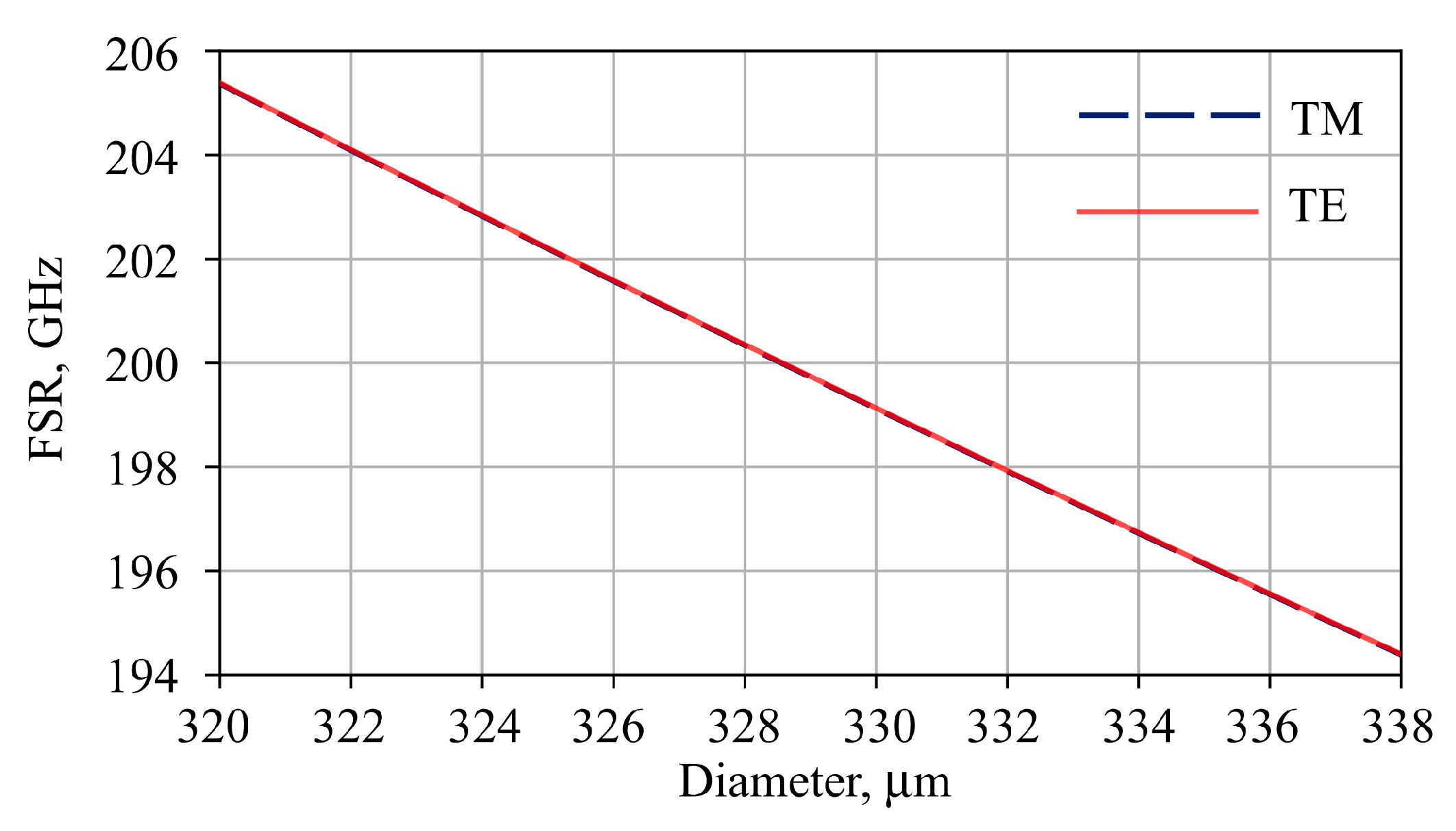
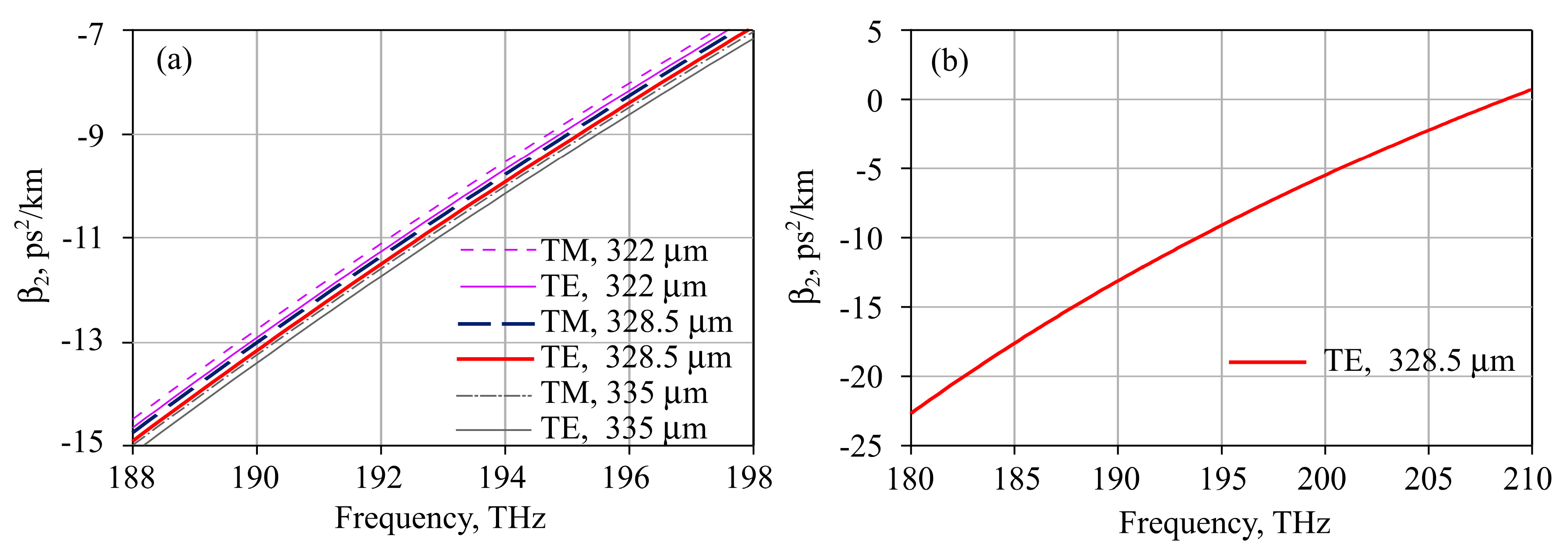
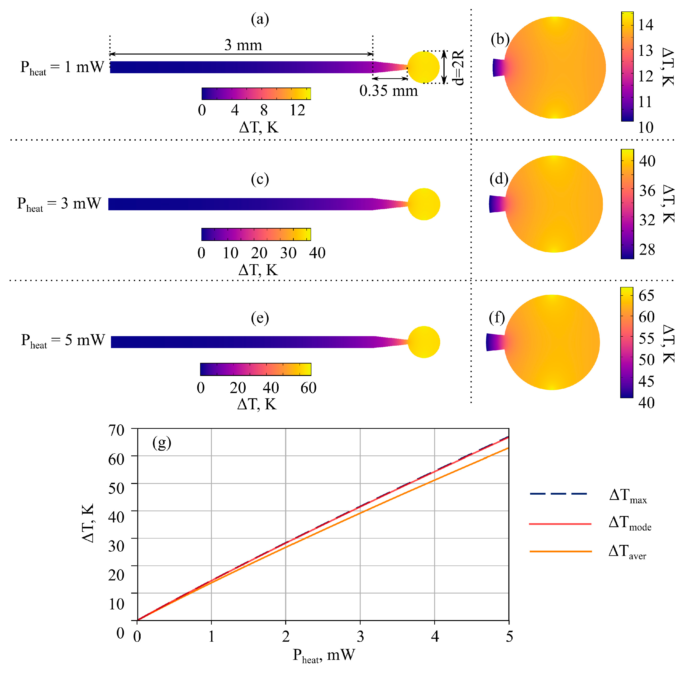
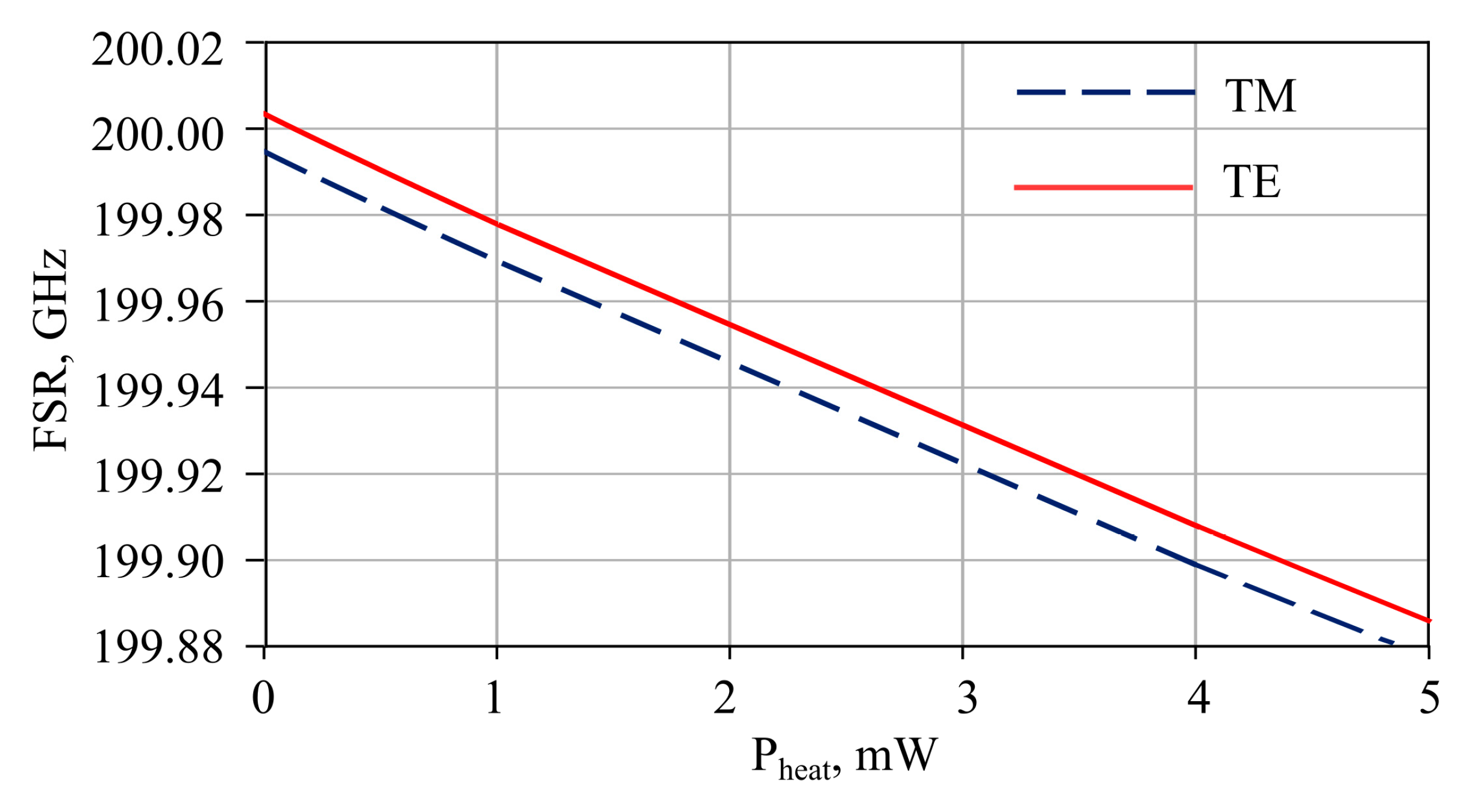
3.1. Microresonator Characteristics

The simulated spatial distribution of the electric field of the fundamental TE mode at the frequency of about 193.1 THz is shown in Figure 2. For the fundamental TM mode, the spatial distribution of the absolute value of the field is very similar and not depicted here.
We solve Equation (1) for different microsphere diameters (d = 2R) to find the optimal one giving FSR of 200 GHz. FSR as a function of the microsphere diameter is plotted in Figure 3 for TE and TM families. These curves for TE and TM modes differ by ~10 MHz but almost coincide for the chosen scale in Figure 3.
Furthermore, using Expressions (4) and (5), we calculate dispersion for the optimal microsphere diameter of ~328.5 μm and for comparison for d = 322 μm and for d = 335 μm for which FSR differs by ±2% from 200 THz and is 204 and 196 THz, respectively. The frequency-dependent dispersions for TE and TM modes for these diameters are plotted in Figure 4a in the 188–198 THz range. It is seen that curves differ slightly. Figure 4b demonstrates the dispersion of the TE family at a wider frequency range for the diameter of 328.5 μm. The dispersion is anomalous at 193.1 THz and the zero-dispersion frequency is about 209 THz. The nonlinear Kerr coefficient is about 3.5 (W·km)−1 at 193.1 THz, and its frequency dependence can be neglected in the C-band.
Next, we estimate the influence of thermal effects on shifts of WGM frequencies and FSR for the optimal diameter. Figure 5a,b demonstrate the calculated shift of eigenfrequencies and FSRs as functions of the temperature increase, respectively. For Figure 5, we assume uniform temperature increase distribution. WGM shifts are almost the same for TE and TM mode families, but FSRs differ by ~10 MHz. FSR difference occurs due to initial “cold” FSR non-equality between TM and TE modes.
To understand when such temperature increases can be achieved, we simulate temperature fields at different powers of the heat source. Temperature distributions for the heat powers of 1, 3, and 5 mW are presented in Figure 6a,b, in Figure 6c,d, and in Figure 6e,f, respectively. Figure 6a,c,e show the complete simulated geometry, including the microsphere itself and the fiber stem, but Figure 6b,d,f show an enlarged microsphere. The temperature inside the microsphere is distributed fairly uniformly. For greater clarity, Figure 6g also shows the dependences of the temperature averaged over the sphere, the temperature averaged over the WGM volume, and the maximum temperature on the heat power. Despite the fact that the full nonlinear heat equation was solved, the dependencies of these temperatures on heat power appear to be almost linear for the considered heat power range.
After finding the temperature distributions and dependencies of temperature increases on the heat power, we plot the FSR versus the power of the heat source (see Figure 7). We also verified that the change in dispersion curves with increasing temperature is negligible for the considered heat powers of a few mW.

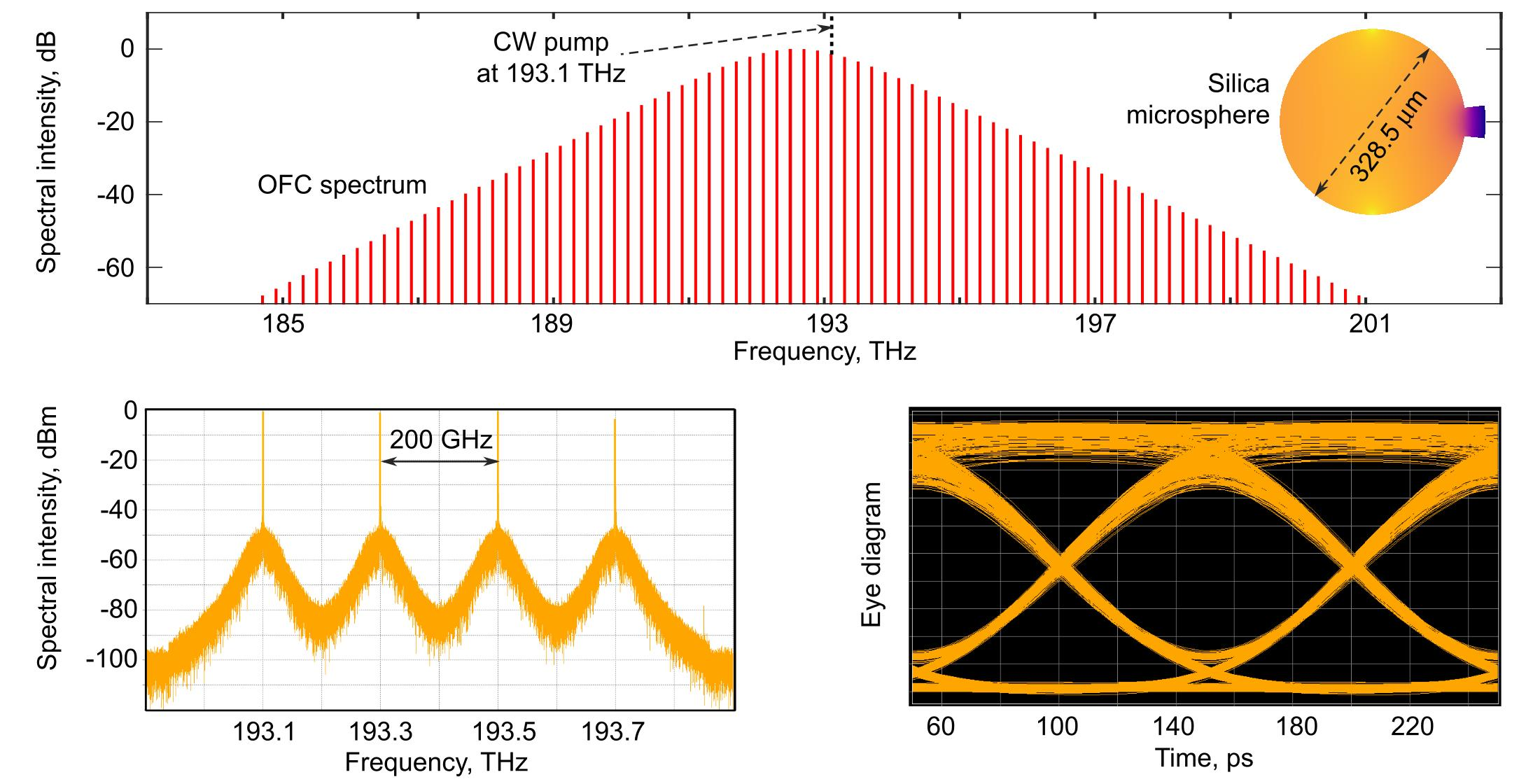
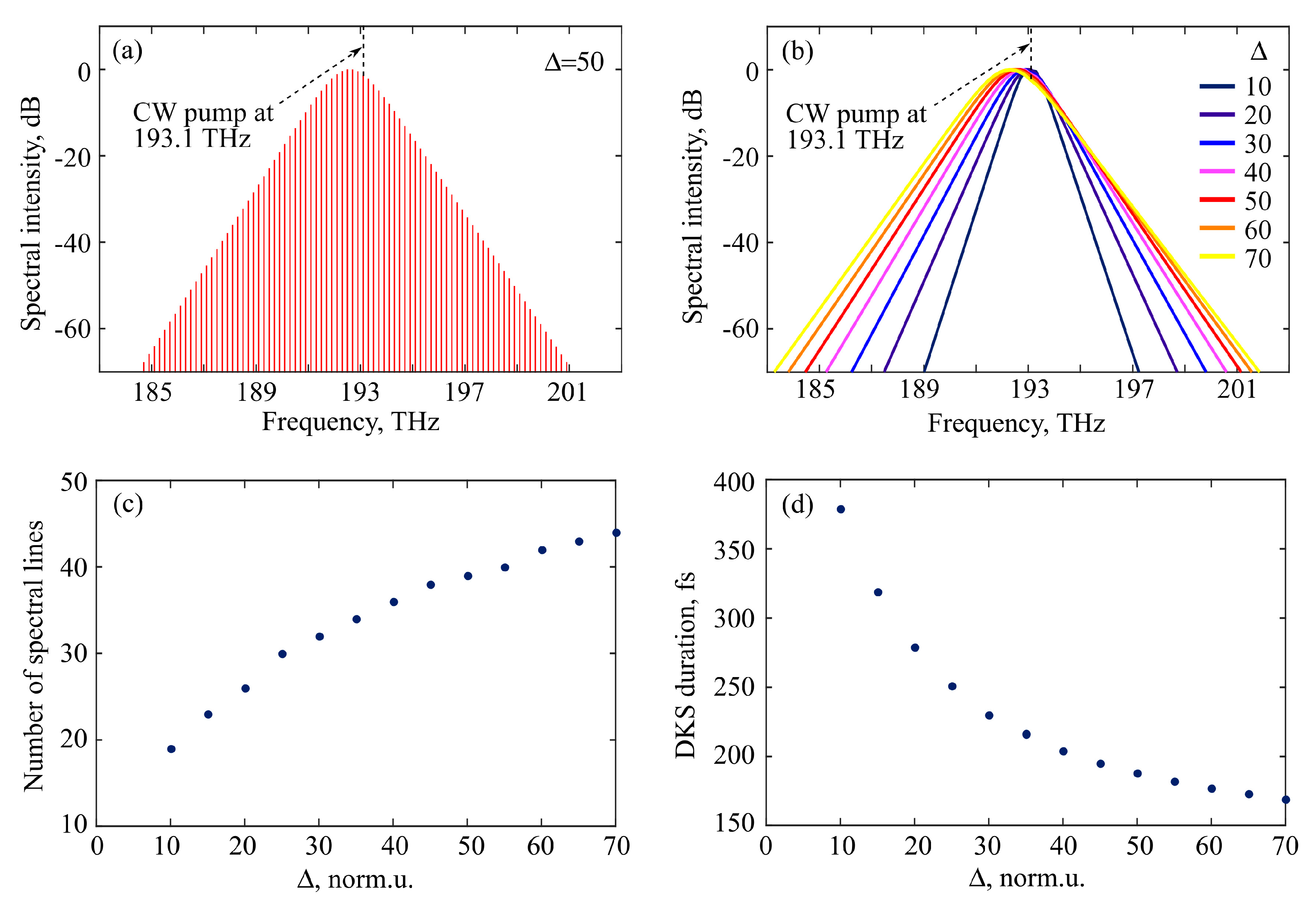
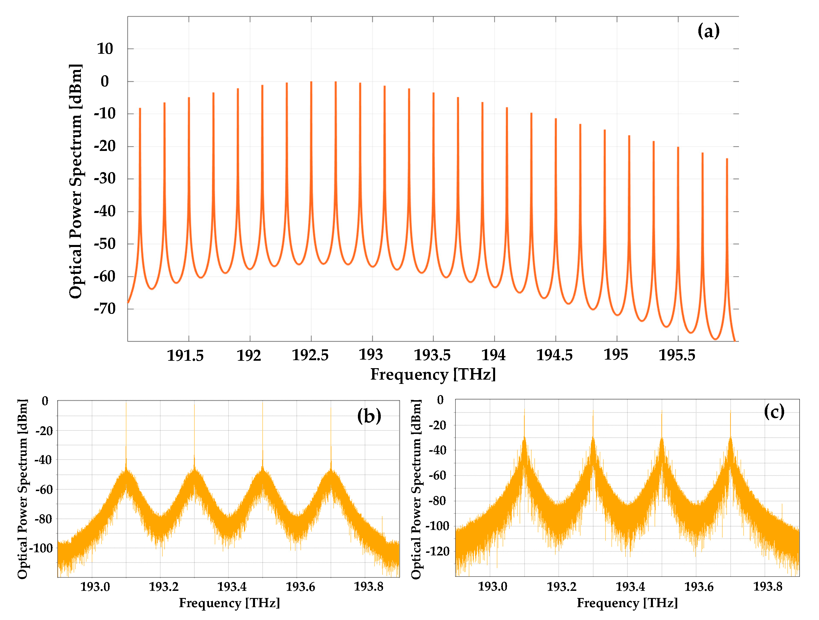
3.2. OFC Generation in DKS Regime

Next, we simulate OFC generation in the DKS regime in the framework of Equation (7). We consider TE modes (for TM modes, the results will be almost the same). It is known that stable DKS can exist in an anomalous dispersion region only for specific conditions for a pump power and normalized detuning Δ (Δ = δp/α) [33,41,42,43]. If the solution in the form of DKS exists in this case, one particular value of DKS peak power corresponds to each admissible detuning [41,43]. For a pump power less than a threshold for this detuning, DKS cannot exist, but CW is a solution. We set pump power slightly higher than this threshold and study properties of generated DKS for different values of Δ. We set pump frequency at 193.1 THz assuming that the nearest resonant WGM can be shifted to 193.1 THz due to the thermal effects caused by partially dissipated pump power and/or external heating of a microsphere. Figure 8a shows the DKS spectrum calculated for Δ = 50. This spectrum is asymmetric with respect to the pump frequency, which is explained by the influence of the Raman nonlinearity and agrees with the results presented in [43,44]. Figure 8b demonstrates the spectral envelopes of stable DKSes simulated for different Δ. The larger the normalized detuning, the broader the spectrum is. For example, for Δ = 10, the spectral width at the level of -30 dB is 3.8 THz, but for Δ = 70, the spectral width is 8.8 THz. Next, we count a quantity of spectral lines (harmonics) in OFC spectra with intensity higher than -30 dB (see Figure 8c). The quantity of lines satisfying this condition increases from 19 for Δ = 10 up to 44 for Δ = 70. For Δ > 70, DKS is unstable and we do not consider intracavity nonlinear dynamics for this case. Note that due to higher-order dispersion, the range of DKS stability is slightly wider than with allowance for only the second-order dispersion presented in [43]. We also find DKS duration (full width at half maximum, FWHM) in the time domain as a function of Δ (see Figure 8d). For larger Δ (when the spectrum is wider), the duration is shorter according to the Fourier-transform limitation (379 fs for Δ = 10 and 169 fs for Δ = 70).

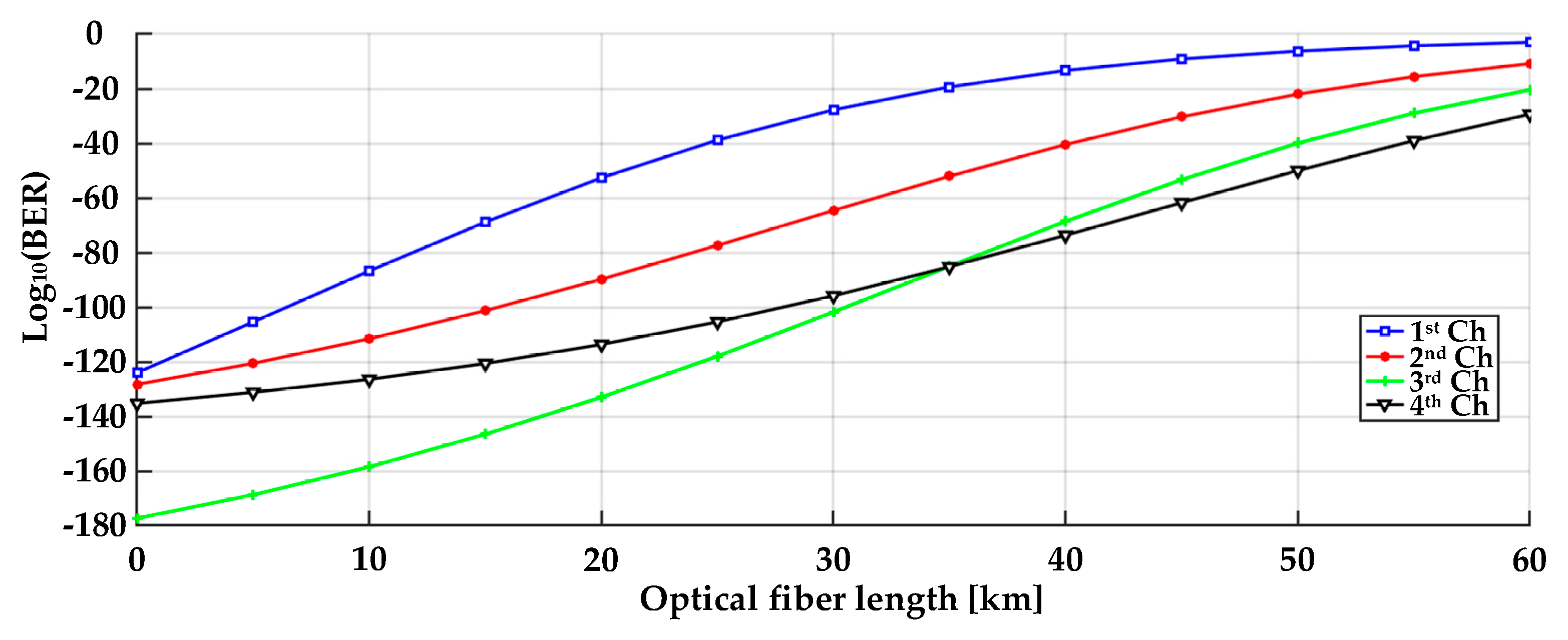
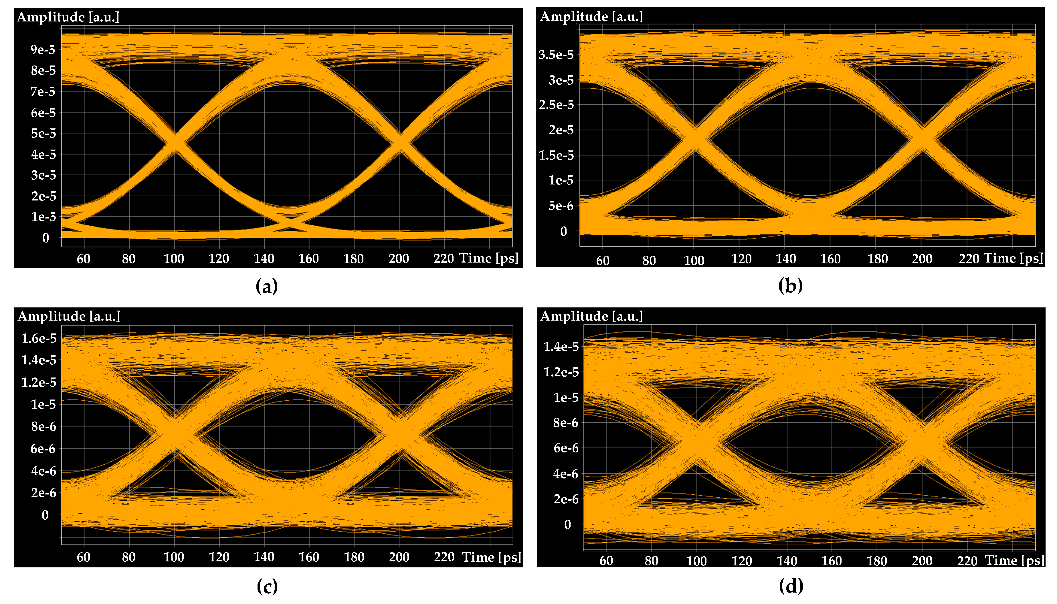
3.3. Architecture and Simulation of 4-Channel 200 GHz Spaced IM/DD WDM-PON Transmission System

The simulation setup of a 4-channel 200 GHz spaced WDM-PON transmission system is depicted in Figure 9.
The output of an amplified spontaneous emission (ASE) optical light source with high output power of up to 23 dBm and spectrum power density of −6 dBm/nm within the 1528–1630 nm band is connected to the input of the user-defined optical band-pass filter (OBPF) where the above-simulated silica microsphere-based OFC output spectrum is implemented. Afterward, the output of comb spectral lines is filtered out by an optical band-pass filter with 760 GHz 3-dB bandwidth to obtain four optical carrier signals. The spectral lines from OFC-WGMR are filtered and de-multiplexed utilizing arrayed-waveguide-grating (AWG) de-multiplexer (de-MUX), which corresponds to wavelength-routed WDM-PON (WR-WDM-PON) architecture. The 3-dB bandwidth of each AWG channel for 200 GHz channel spacing was set to 87.3 GHz. The spectrum of the optical signal at the output of the user-defined OBPF with implemented microsphere-based OFC, the obtained band-pass filtering for four optical carriers, and the output of AWG de-multiplexer after back-to-back (B2B) transmission are shown in Figure 10a–c, respectively. Note that Figure 10a contains OFC lines simulated in Section 3.2 and presented in Figure 8a. The Lorentzian line shape is assumed.
Carriers (comb spectral lines) separated with AWG de-MUX are fed to the optical input of the Mach–Zehnder modulators (MZMs). The electrical data signals are provided by PRBS from PRBS generator through NRZ driver, which encodes the logical data by using the non-return-to-zero (NRZ) technique generating electrical NRZ signals with a bit rate of 10 Gbit/s. Each MZM, having a 3-dB bandwidth of 12 GHz and 20 dB extinction ratio, is driven by NRZ signal S1(t) [45].
Optical signals from each transmitter’s (Tx) MZM are coupled together using an AWG multiplexer (MUX). The combined, modulated optical signals are transmitted over 20 up to 60 km ITU-T G.652 single-mode fiber (SMF) span, with 0.02 dB/km attenuation and 16 ps/nm/km dispersion coefficients at 1550 nm reference wavelength. According to NG-PON2 (ITU-T G.989.2) recommendation, the specified valid optical link distances are up to 40 km, but longer lengths are supported and reach network distance up to 60 km. Therefore, we extend the optical link section to maximal PON transmission distance of 60 km.
The receiver (Rx) consists of a PIN photodiode with 3-dB bandwidth of 12 GHz, sensitivity of −18 dBm for BER of 10−12, and responsivity of 0.65 A/W [46]. Afterward, the received, modulated signal is filtered by an electrical low-pass filter (LPF) with 7.5 GHz 3-dB electrical bandwidth. The electrical signal analyzer is used to measure the received signal, e.g., showing bit pattern and BER.
The performance indicators as BER and eye diagrams of the received signal verify the feasibility of the designed transmission. The obtained BER results of each optical channel with respect to optical network link section length of up to 60 km over SMF for NRZ modulated 4-channel IM/DD WDM-PON transmission system with 200 GHz spacing is shown in Figure 11.
We observed that the worst-performing channel in terms of BER performance was the 1st channel (193.1 THz). In the best scenario, the highest system performance was observed for the 4th optical channel (193.7 THz), where BER of the received signal after transmission over 60 km SMF fiber link was 4.5 × 10⁻³⁰. The drop in the BER performance is mainly affected by the power and noise floor variation between comb lines and phase noise. In such a case, the comb source for the data transmission system must ensure minimal optical carrier-to-noise power ratio (OCNR) that a comb line must have to be useful for data transmission.
We have demonstrated 4-channel 200 GHz spaced IM/DD WDM-PON transmission system with operating data rates of 10 Gbit/s per channel over different SMF fiber link section lengths up to 60 km, please see Figure 12. As shown in Figure 12a–c, for the 1st optical channel with worst BER performance in B2B configuration, as well after 20 and 40 km, the signal quality is very good, the eye is open, and error-free transmission can be provided. After 60 km transmission, the BER of the received signal was 9.1 × 10⁻⁴, please see Figure 12d. Therefore, our investigated 200 GHz spaced OFC-WGMR light source-based IM/DD WDM-PON transmission system is fully capable of providing 10 Gbit/s of NRZ-OOK modulated signal transmission according to NG-PON2 recommendation specified valid optical link distances of 40 km. That means it is technically challenging to ensure such transmission stability for longer distances by the use of OFC-WGMR as an optical light source for telecommunication applications. More comprehensive future research on the limits of the OFCs parameters for implementing the PON transmission systems segment of such a long transmission distance (60 km) is desirable.

4. Discussion and Conclusions

We proposed and numerically investigated a simple design of silica microsphere-based OFC generator in the optical C-band producing stable DKS and simulated its implementation in the WDM data transmission system. The optimal microsphere diameter of 328.5 μm provides an FSR of 200 GHz, according to ITU-T G. 694.1 recommendation. We considered the TE and TM families of fundamental WGMs and found that the FSR values practically coincide. With a slight deviation of the diameter from the optimal value, FSR changes linearly. For example, if a diameter changes by ±2%, FSR changes by ±2% too (for diameters of 322 μm and 335 μm, FSRs are 204 and 196 THz, respectively). We also investigated the influence of thermo-optical effects on WGM shift and FSR. The WGM shift and FSR are almost linear functions of temperature. When the temperature rises by 60 C, the WGM eigenfrequencies decrease by 100 GHz, but FSR decreases by 0.1 GHz. We simulated steady-state temperature distribution originated from partial pump power dissipation. Although the heat source was located in a small volume equal to the effective mode volume, the temperature distribution was fairly uniform over the microsphere.
The dispersion as a function of frequency and the nonlinear Kerr coefficient were calculated. In the C-band, the dispersion is anomalous (of the order of −10 ps2/km). Both material and waveguide contributions are important here. The zero-dispersion frequency is about 209 THz. Dispersion curves for TE and TM fundamental modes differ slightly. The nonlinear Kerr coefficient is about 3.5 (W·km)−1. It was also verified that the change in dispersion with temperature increasing was negligible for the considered heat powers of a few mW.
We simulated OFC generation in the DKS regime for the range of normalized detuning Δ where stable DKS can exist. When Δ changes from 10 to 70, the spectral width at the level of −30 dB grows from ~3.8 THz to 8.8 THz, and the DKS duration in the time domain shortened from 379 fs to 169 fs (FWHM). DKS spectra are asymmetric with respect to the pump frequency at 193.1 THz, which is explained by the influence of the Raman nonlinearity and agrees with the results presented in [43]. We assumed that OFC with FSR of 200 GHz could be anchored to 193.1 THz using temperature control. Narrow-band CW pump can be coupled to a microresonator using a fiber taper and generated OFC can be extracted from a microresonator with the same taper [28]. Note that a reliable way to generate DKS and influence of thermal effects on the dynamics of DKS formation is considered in [47]. The experimental features of the DKS generation in a silica microsphere are reported in [27]. For attaining OFCs with lower FSRs, bottle microresonators can be used as predicted in [48,49].
We have also simulated a 4-channel 200 GHz spaced IM/DD WDM-PON transmission system with operating data rates of 10 Gbit/s per channel over different SMF fiber link lengths up to 60 km. The variation in the BER performance of the OFC-WGMR portable light source is observed and is mainly affected by the power and noise floor variation between carriers. Therefore, the proposed 200 GHz spaced OFC-WCOMB light source-based IM/DD WDM-PON transmission system is fully capable of providing 10 Gbit/s of NRZ modulated signal transmission to NG-PON2 recommendation specified valid optical link distances up to 40 km.
Note that the considered system is attractive to service providers for substituting existing central office (CO) architecture. The major drawback of the current CO architecture is that individual lasers’ array is used to sustain WDM data channels; however, here we use an OFC generator, employing only one single laser. An OFC generator based on silica microspheres is a cost-effective solution, making the possibility to add more end-users to one PON. The latter is especially interesting for those countries where service providers still use copper infrastructure, considering that service providers will need to install fewer PONs to connect a more significant number of end-users. So, our solution can potentially lower expenses to upgrade existing fiber infrastructure and change infrastructure in favor of optical fiber systems.

Author Contributions

Conceptualization, E.A.A., A.V.A. and V.B.; methodology, E.A.A., M.P.M. and S.S.; software, E.A.A., M.P.M., L.S. and I.L.; validation, E.A.A., M.P.M. and T.S.; formal analysis, R.M., I.V.O. and A.S.; investigation, E.A.A., M.P.M., A.V.A., R.A.A., R.M., M.D.T., S.S., G.L. and V.B.; data curation, M.P.M., L.S. and I.L.; writing—original draft preparation, E.A.A., R.M. and T.S.; writing—review and editing M.P.M., A.V.A., R.M. and S.S.; visualization, E.A.A., M.P.M. and T.S.; supervision, E.A.A. and V.B.; project administration, E.A.A., A.V.A. and V.B. All authors have read and agreed to the published version of the manuscript.

Funding

This research was funded by the Mega-grant of the Ministry of Science and Higher Education of the Russian Federation, Contract No.14.W03.31.0032 (conceptualization and development of the optical frequency comb generator) and by the Russian Science Foundation, Grant No. 20-72-10188 (calculation of microresonator characteristics and numerical simulation of dissipative Kerr solitons) and has been supported by the European Regional Development Fund project No. 1.1.1.1/18/A/155 “Development of optical frequency comb generator based on a whispering gallery mode microresonator and its applications in telecommunications”, the Doctoral Grant programme of Riga Technical University in Latvia.

Conflicts of Interest

The authors declare no conflict of interest.

Abbreviations

OFCoptical frequency comb
WGMwhispering gallery mode
WDMwavelength-division multiplexing
PONpassive optical network
FSRfree spectral range
TMtransverse magnetic
TEtransverse electric
CWcontinuous wave
DKSdissipative Kerr soliton
FWHMfull width at half maximum
BERbit error rate
NRZnon-return-to-zero
OOKon-off keying
IM/DDintensity modulation direct detection
NG-PON2Next-generation PON
ASEamplified spontaneous emission
ASIamplified spontaneous emission light source
AWGarrayed-waveguide-grating
LPFlow-pass filter
MZMMach–Zehnder modulator
OBPFoptical band-pass filter
WGMRwhispering gallery mode resonator
MUXmultiplexed
de-MUXdemultiplexer
PINphotodiode
SMFsingle-mode fiber
B2Bback-to-back
WRwavelength-routed
QoTquality of transmission
ITU-TInternational Telecommunication Union–telecommunication standardization sector
OCNRoptical carrier-to-noise power ratio
COcentral office

References

  1. Pasquazi, A.; Peccianti, M.; Razzari, L.; Moss, D.J.; Coen, S.; Erkintalo, M.; Chembo, Y.K.; Hansson, T.; Wabnitz, S.; Del’Haye, P.; et al. Micro-combs: A novel generation of optical sources. Phys. Rep. 2018, 729, 1–81. [Google Scholar] [CrossRef]
  2. Strekalov, D.V.; Marquardt, C.; Matsko, A.B.; Schwefel, H.G.; Leuchs, G. Nonlinear and quantum optics with whispering gallery resonators. J. Opt. 2016, 18, 123002. [Google Scholar] [CrossRef] [Green Version]
  3. Suh, M.G.; Yang, Q.F.; Yang, K.Y.; Yi, X.; Vahala, K.J. Microresonator soliton dual-comb spectroscopy. Science 2016, 354, 600–603. [Google Scholar] [CrossRef] [Green Version]
  4. Yu, M.; Okawachi, Y.; Griffith, A.G.; Picqué, N.; Lipson, M.; Gaeta, A.L. Silicon-chip-based mid-infrared dual-comb spectroscopy. Nat. Commun. 2018, 9, 1869. [Google Scholar] [CrossRef] [Green Version]
  5. Xue, X.; Xuan, Y.; Kim, H.J.; Wang, J.; Leaird, D.E.; Qi, M.; Weiner, A.M. Programmable single-bandpass photonic RF filter based on Kerr comb from a microring. J. Lightw. Technol. 2014, 4, 3557–3565. [Google Scholar] [CrossRef]
  6. Suh, M.G.; Yi, X.; Lai, Y.H.; Leifer, S.; Grudinin, I.S.; Vasisht, G.; Martin, E.C.; Fitzgerald, M.P.; Doppmann, G.; Wang, J.; et al. Searching for exoplanets using a microresonator astrocomb. Nat. Photonics 2019, 13, 25–30. [Google Scholar] [CrossRef] [Green Version]
  7. Kues, M.; Reimer, C.; Lukens, J.M.; Munro, W.J.; Weiner, A.M.; Moss, D.J.; Morandotti, R. Quantum optical microcombs. Nat. Photonics 2019, 13, 170–179. [Google Scholar] [CrossRef] [Green Version]
  8. Engin, E.; Bonneau, D.; Natarajan, C.M.; Clark, A.S.; Tanner, M.G.; Hadfield, R.H.; Dorenbos, S.N.; Zwiller, V.; Ohira, K.; Suzuki, N.; et al. Photon pair generation in a silicon micro-ring resonator with reverse bias enhancement. Opt. Express 2013, 21, 27826–27834. [Google Scholar] [CrossRef]
  9. Monteiro, F.; Martin, A.; Sanguinetti, B.; Zbinden, H.; Thew, R.T. Narrowband photon pair source for quantum networks. Opt. Express 2014, 22, 4371–4378. [Google Scholar] [CrossRef]
  10. Kumar, R.; Ong, J.R.; Recchio, J.; Srinivasan, K.; Mookherjea, S. Spectrally multiplexed and tunable wavelength photon pairs at 1.55 μm from a silicon coupled-resonator optical waveguide. Opt. Lett. 2013, 38, 2969–2971. [Google Scholar] [CrossRef]
  11. Raussendorf, R.; Briegel, H.J. A one-way quantum computer. Phys. Rev. Lett. 2001, 86, 5188–5191. [Google Scholar] [CrossRef]
  12. Walther, P.; Resch, K.J.; Rudolph, T.; Schenck, E.; Weinfurter, H.; Vedral, V.; Aspelmeyer, M.; Zeilinger, A. Experimental one-way quantum computing. Nature 2005, 434, 169–176. [Google Scholar] [CrossRef] [PubMed]
  13. Company, V.T.; Scroder, J.; Fulop, A.; Mazur, M.; Lundberg, L.; Helhason, O.B.; Karlsson, M.; Andrekson, P.A. Laser Frequency Combs for Coherent Optical Communications. J. Lightw. Technol. 2019, 37, 1663–1670. [Google Scholar] [CrossRef] [Green Version]
  14. Pfeifle, J.; Weimann, C.; Bach, F.; Riemensberger, J.; Hartinger, K.; Hillerkuss, D.; Jordan, M.; Holtzwarth, B.; Kippenberg, T.J.; Leuthold, J.; et al. Microresonator-Based Optical Frequency Combs for High-Bitrate WDM Data Transmission. In Proceedings of the Optical Fiber Communication Conference, Los Angeles, CA, USA, 4–8 March 2012. [Google Scholar] [CrossRef]
  15. Pfeifle, J.; Brasch, V.; Lauermann, M.; Yu, Y.; Wegner, D.; Herr, T.; Hartinger, K.; Schindler, P.; Li, J.; Hillerkuss, D.; et al. Coherent terabit communications with microresonator Kerr frequency combs. Nat. Photonics 2014, 8, 375–380. [Google Scholar] [CrossRef] [PubMed] [Green Version]
  16. Pfeifle, J.; Coillet, A.; Henriet, R.; Saleh, K.; Schindler, P.; Weimann, C.; Freude, W.; Balakireva, I.V.; Larger, L.; Koos, C.; et al. Optimally Coherent Kerr Combs Generated with Crystalline Whispering Gallery Mode Resonators for Ultrahigh Capacity Fiber Communications. Phys. Rev. Lett. 2015, 114, 093902. [Google Scholar] [CrossRef]
  17. Marin-Palomo, P.; Kemal, J.N.; Karpov, M.; Kordts, A.; Pfeifle, J.; Pfeiffer, M.H.P.; Trocha, P.; Wolf, S.; Brasch, V.; Anderson, M.H.; et al. Microresonator-based solitons for massively parallel coherent optical communications. Nature 2017, 546, 274–279. [Google Scholar] [CrossRef] [Green Version]
  18. Pfeifle., J.; Yu, Y.; Schindler, P.C.; Brasch, V.; Weimann, C.; Hartinger, K.; Holzwarth, R.; Freude, W.; Kippenberg, T.J.; Koos, C. Transmission of a 1.44 Tbit/s data stream using a feedback-stabilized SiN Kerr Frequency Comb Source. In Proceedings of the Optical Fiber Communication Conference, San Francisco, CA, USA, 9–13 March 2014. [Google Scholar] [CrossRef]
  19. Pfeifle, J.; Kordts, A.; Marin, P.; Karpov, M.; Pfeiffer, M.; Brasch, V.; Rosenberger, R.; Kemal, J.; Wolf, S.; Freude, W.; et al. Full C and L-Band Transmission at 20 Tbit/s Using Cavity-Soliton Kerr Frequency Comb Source. In Proceedings of the Conference on Lasers and Electro-Optics (CLEO), San Jose, CA, USA, 10–15 May 2015. [Google Scholar] [CrossRef]
  20. Fülöp, A.; Mazur, M.; Lorences-Riesgo, A.; Helgason, Ó.B.; Wang, P.H.; Xuan, Y.; Leaird, D.E.; Qi, M.; Andrekson, P.A.; Weiner, A.M.; et al. High-order coherent communications using mode-locked dark-pulse Kerr combs from microresonators. Nat. Commun. 2018, 9, 1598. [Google Scholar] [CrossRef] [Green Version]
  21. Addanki, S.; Yupapin, P.; Amiri, I.S. Enhanced NRZ multi-carriers modulation technologies for microresonators in THz technology applications. Results Phys. 2019, 12, 178–189. [Google Scholar] [CrossRef]
  22. Hu, H.; Da Ros, F.; Pu, M.; Ye, F.; Ingerslev, K.; Da Silva, E.P.; Nooruzzaman, M.; Semenova, E.; Guan, P.; Zibar, D.; et al. Single-source chip-based frequency comb enabling extreme parallel data transmission. Nat. Photonics 2018, 12, 469–473. [Google Scholar] [CrossRef]
  23. Peichang, L.; Changjing, B.; Almaiman, A.; Kordts, A.; Karpov, M.; Pfeiffer, M.H.P.; Lin, Z.; Alishahi, F.; Yinwen, C.; Kaiheng, Z.; et al. Demonstration of Multiple Kerr-frequency-Comb Generation Using Different Lines From Another Kerr Comb Located Up to 50 km Away. J. Lightw. Technol. 2019, 37, 579–584. [Google Scholar] [CrossRef]
  24. Kovach, A.; Chen, D.; He, J.; Choi, H.; Dogan, A.H.; Ghasemkhani, M.; Taheri, H.; Armani, A.M. Emerging material systems for integrated optical Kerr frequency combs. Adv. Opt. Photonics 2020, 12, 135–222. [Google Scholar] [CrossRef] [Green Version]
  25. Gorodetsky, M.L.; Savchenkov, A.A.; Ilchenko, V.S. Ultimate Q of optical microsphere resonators. Opt. Lett. 1996, 21, 453–455. [Google Scholar] [CrossRef] [PubMed]
  26. Spillane, S.M.; Kippenberg, T.J.; Vahala, K.J. Ultralow-threshold Raman laser using a spherical dielectric microcavity. Nature 2002, 415, 621–623. [Google Scholar] [CrossRef] [PubMed]
  27. Webb, K.E.; Erkintalo, M.; Coen, S.; Murdoch, S.G. Experimental observation of coherent cavity soliton frequency combs in silica microspheres. Opt. Lett. 2016, 41, 4613–4616. [Google Scholar] [CrossRef] [Green Version]
  28. Andrianov, A.V.; Anashkina, E.A. Single-mode silica microsphere Raman laser tunable in the U-band and beyond. Results Phys. 2020, 17, 103084. [Google Scholar] [CrossRef]
  29. ITU-T G.694.1 Recommendation. Spectral Grids for WDM Applications: DWDM Frequency Grid. Available online: https://www.itu.int/itu-t/recommendations/rec.aspx?rec=11482&lang=en (accessed on 10 September 2020).
  30. Fujii, S.; Tanabe, T. Dispersion engineering and measurement of whispering gallery mode microresonator for Kerr frequency comb generation. Nanophotonics 2020, 9, 1087–1104. [Google Scholar] [CrossRef] [Green Version]
  31. Godey, C.; Balakireva, I.V.; Coillet, A.; Chembo, Y.K. Stability analysis of the spatiotemporal Lugiato-Lefever model for Kerr optical frequency combs in the anomalous and normal dispersion regimes. Phys. Rev. A 2014, 89, 063814. [Google Scholar] [CrossRef] [Green Version]
  32. Carmon, T.; Yang, L.; Vahala, K.J. Dynamical thermal behavior and thermal self-stability of microcavities. Opt. Express 2004, 12, 4742–4750. [Google Scholar] [CrossRef] [Green Version]
  33. Herr, T.; Brasch, V.; Jost, J.D.; Wang, C.Y.; Kondratiev, N.M.; Gorodetsky, M.L.; Kippenberg, T.J. Temporal solitons in optical microresonators. Nat. Photonics 2014, 8, 145–152. [Google Scholar] [CrossRef] [Green Version]
  34. Oraevsky, A.N. Whispering-gallery waves. Quantum Electron. 2020, 32, 377–400. [Google Scholar] [CrossRef]
  35. Agrawal, G.P. Nonlinear Fiber Optics, 6th ed.; Elsevier: London, UK, 2019. [Google Scholar]
  36. Powell, M.J.D. A hybrid method for nonlinear equations. In Numerical Methods for Nonlinear Equations; Rabinowitz, P., Ed.; Gordon and Breach: London, UK, 1970. [Google Scholar]
  37. Andrianov, A.V.; Marisova, M.P.; Dorofeev, V.V.; Anashkina, E.A. Thermal shift of whispering gallery modes in tellurite glass microspheres. Results Phys. 2020, 17, 103128. [Google Scholar] [CrossRef]
  38. Anashkina, E.A.; Sorokin, A.A.; Marisova, M.P.; Andrianov, A.V. Development and numerical simulation of spherical microresonators based on SiO2–GeO2 germanosilicate glasses for generation of optical frequency combs. Quantum Electron. 2019, 49, 371–376. [Google Scholar] [CrossRef]
  39. Anashkina, E.A.; Marisova, M.P.; Sorokin, A.A.; Andrianov, A.V. Numerical simulation of mid-infrared optical frequency comb generation in chalcogenide As2S3 microbubble resonators. Photonics 2019, 6, 55. [Google Scholar] [CrossRef] [Green Version]
  40. ITU-T Recommendation G.989.2. Digital Sections and Digital Line System—Optical Linesystems for Local and Access Networks—40-Gigabit-Capable Passive Optical Networks 2 (NG-PON2): Physical Media Dependent (PMD) Layer Specification; ITU-T: Geneva, Switzerland, 2019; pp. 1–122. [Google Scholar]
  41. Coen, S.; Erkintalo, M. Universal scaling laws of Kerr frequency combs. Opt. Lett. 2013, 38, 1790–1792. [Google Scholar] [CrossRef] [Green Version]
  42. Shen, B.; Chang, L.; Liu, J.; Wang, H.; Yang, Q.F.; Xiang, C.; Wang, R.N.; He, J.; Liu, T.; Xie, W.; et al. Integrated turnkey soliton microcombs. Nature 2020, 582, 365–369. [Google Scholar] [CrossRef] [PubMed]
  43. Wang, Y.; Anderson, M.; Coen, S.; Murdoch, S.G.; Erkintalo, M. Stimulated Raman scattering imposes fundamental limits to the duration and bandwidth of temporal cavity solitons. Phys. Rev. Lett. 2018, 120, 053902. [Google Scholar] [CrossRef] [Green Version]
  44. Milián, C.; Gorbach, A.V.; Taki, M.; Yulin, A.V.; Skryabin, D.V. Solitons and frequency combs in silica microring resonators: Interplay of the Raman and higher-order dispersion effects. Phys. Rev. A 2015, 92, 033851. [Google Scholar] [CrossRef] [Green Version]
  45. IXblue Photonics. MX-LN Series 1550 nm Band Intensity Modulators; Technical Specification; iXblue Photonics: Paris, France, 2019; pp. 1–6. [Google Scholar]
  46. Amonics. 10G Receiver Module; Technical Specification; Amonics Ltd.: Hong Kong, China, 2008; pp. 1–2. [Google Scholar]
  47. Lobanov, V.E.; Lihachev, G.V.; Pavlov, N.G.; Cherenkov, A.V.; Kippenberg, T.J.; Gorodetsky, M.L. Harmonization of chaos into a soliton in Kerr frequency combs. Opt. Express 2016, 24, 27382–27394. [Google Scholar] [CrossRef]
  48. Suchkov, S.V.; Sumetsky, M.; Sukhorukov, A.A. Frequency comb generation in SNAP bottle resonators. Opt. Lett. 2017, 42, 2149–2152. [Google Scholar] [CrossRef]
  49. Oreshnikov, I.; Skryabin, D.V. Multiple nonlinear resonances and frequency combs in bottle microresonators. Opt. Express 2017, 25, 10306–10311. [Google Scholar] [CrossRef]
Figure 1. Schematic diagram of the whispering gallery modes (WGMs) for a microsphere at the initial temperature T0 and heated by ΔT.
Photonics 07 00072 g001
Figure 2. The normalized absolute value of the electric field for transverse electric (TE) mode at the eigenfrequency of about 193.1 THz in the equatorial plane (a) and in a plane perpendicular to equatorial one (b).
Photonics 07 00072 g002
Figure 3. FSR as a function of a microsphere diameter for transverse magnetic (TM) and TE modes.
Photonics 07 00072 g003
Figure 4. (a) Dispersion as a function of frequency for microspheres with indicated diameters for TE and TM modes. (b) Dispersion as a function of frequency for a microsphere with a diameter of 328.5 μm for TE modes.
Photonics 07 00072 g004
Figure 5. WGM shift (a) and free spectral range (FSR) (b) as functions of temperature increase for a microsphere with a diameter of ~328.5 μm.
Photonics 07 00072 g005
Figure 6. Temperature distributions for heat powers: 1 mW (a,b); 3 mW (c,d); and 5 mW (e,f). The temperature increase as a function of heat power (g). All subfigures are calculated for a microsphere with a diameter of ~328.5 μm.
Photonics 07 00072 g006
Figure 7. Dependence of FSR on heat power for a microsphere with a diameter of ~328.5 μm.
Photonics 07 00072 g007
Figure 8. (a) Normalized intracavity spectral intensity of DKS for Δ =50. (b) Envelopes of normalized DKS spectra. (c) Number of spectral lines (harmonics) with spectral intensity higher than −30 dB relative to the maximum as a function of normalized detuning. (d) FWHM DKS duration as a function of normalized detuning.
Photonics 07 00072 g008
Figure 9. Simulation model of the 4-channel 200 GHz spaced IM/DD WDM-PON system used for the designed silica microsphere-based OFC comb spectrum implementation and performance assessment where ASE—Amplified spontaneous emission light source, AWG—Arrayed-waveguide-grating, LPF—Low-pass filter, MZM—Mach–Zehnder modulator, OBPF—Optical band-pass filter, OFC-WGMR—Optical frequency comb generator based on whispering gallery mode resonator, PIN—photodiode, SMF—single-mode fiber.
Photonics 07 00072 g009
Figure 10. Optical spectra: (a) after user-defined OBPF with implemented microsphere-based OFC comb source, (b) after OBPF-four optical carriers from microsphere-based OFC comb source, (c) modulated optical carriers after B2B transmission for 4-channel 200 GHz spaced IM/DD WDM-PON system operating at 10 Gbit/s per channel.
Photonics 07 00072 g010
Figure 11. Quality of transmission (QoT) characteristics for the 10 Gbit/s NRZ-OOK signals in the 4-channel 200 GHz spaced IM/DD WDM-PON system: the fair comparison of BER vs. Optical fiber length for implemented microsphere-based OFC comb carriers’ performance.
Photonics 07 00072 g011
Figure 12. Eye diagrams of the received signal: (a) after B2B, (b) after 20 km, (c) after 40 km, (d) after 60 km transmission via SMF optical link section for investigated 4-channel 200 GHz spaced IM/DD WDM-PON system operating at 10 Gbit/s per channel.
Photonics 07 00072 g012

