Abstract
The mutual and injection locking characteristics of two integrated lasers are compared, both on and off-chip. In this study, two integrated single facet slotted Fabry–Pérot lasers are utilised to develop the measurement technique used to examine the different operational regimes arising from optically locking a semiconductor diode laser. The technique employed used an optical spectrum analyser (OSA), an electrical spectrum analyser (ESA) and a high speed oscilloscope (HSO). The wavelengths of the lasers are measured on the OSA and the selected optical mode for locking is identified. The region of injection locking and various other regions of dynamical behaviour between the lasers are observed on the ESA. The time trace information of the system is obtained from the HSO and performing the FFT (Fast Fourier Transform) of the time traces returns the power spectra. Using these tools, the similarities and differences between off-chip injection locking with an isolator, and on-chip mutual locking are examined.
1. Introduction
Optical injection locking of semiconductor lasers has been an area of great interest since the early 1980s [1]. The theoretical and experimental study of injection locked semiconductor lasers has resulted in many applications. For example, injection locking can be used to demultiplex an optical comb [2]. The comb lines can then be modulated individually before recombining the signal to a coherent comb for use in coherent wavelength division multiplexing [3]. Injection locking can also be used to generate multiple phase locked coherent outputs [4], which are required for many modern day modulation formats [5].
Injection locking [1,6,7] involves coupling an external optical signal from one laser into another. Injection locking is separate from mutual coupling [8,9,10] in that the light only propagates in one direction. The source laser is usually referred to as the master laser while the laser to which the light is injected is referred to as the slave laser. The master laser is often higher powered than the slave laser. In a typical situation, the discrete lasers of the master–slave system are coupled together using free-space optics or via optical fibre using an optical isolator to eliminate any optical coupling from the slave back to the master laser.
Due to the ever increasing demand being put on optical communication networks, there is a significant move towards developing integrated devices to replace discrete optical components. Photonic integrated circuits (PICs) offer an effective solution for the advancement of system level functions at a compact scale. Integration vastly decreases the size of these systems and allows for lower power consumption and reduced cost. However, the implementation of injection locking in such a system is not possible without feasible integrated isolators. The resulting PIC without an isolator is no longer purely master–slave but is now bidirectional, or mutual. However, stable injection locking (or asymmetric mutual locking) between two slotted Fabry–Pérot (SFP) lasers on-chip has been demonstrated for the case where one laser (designated as the master) is much higher powered than the other laser (designated as the slave) [11]. For lasers that are mutually coupled on a PIC, we are now referring to the mutual coupling interaction as injection locking, when the powers of the lasers are highly asymmetric. In this case, we refer to the higher powered laser as the master and the lower power laser as the slave. In order to reliably enable applications that are based on injection locked lasers in a PIC, the limits of injection locking a system of integrated semiconductor lasers need to be studied. To carry out this investigation, it is necessary to develop a technique for efficiently detecting and measuring optical injection locking. Thus, both the measurement techniques and the results are presented in this paper.
To begin, a simpler off-chip coupling regime [11] is investigated where the lasers are isolated from each other on-chip, by reverse biasing the waveguide interconnect between the lasers, and the light from the master is coupled into the slave through an optical isolator. This prevents the mutual feedback between the lasers that occurs on-chip, making the injection locking of the system less complex. Without the feedback, an objective baseline is obtained for the future comparison between mutually injection locked lasers on-chip.
In this paper, we first investigate the output of an integrated injection locked single facet slotted Fabry–Perot (SF-SFP) laser [12] using off-chip coupling. Measurements were done using an optical spectrum analyser (OSA), an electrical spectrum analyser (ESA) and a high speed oscilloscope (HSO). The behavioural regimes of the lasers as they undergo injection locking and an effective method to detect injection locking are discussed. The method of detection is then used to study the on-chip coupling regime where there is feedback between the lasers. New and unexpected laser interactions are found and reported in this mutual coupling regime.
2. The Photonic Integrated Circuit
The PIC used consisted of two identical (within fabrication tolerances) SF-SFP lasers coupled together through a 615 m long waveguide interconnect. A schematic of the full device is shown in Figure 1. The single facet lasers consisted of a 650 m long gain section and a 762 m long mirror section, comprised of seven etched slots, each with a gap of 1 m and 108 m separation between the slots. The epitaxial structure used was commercially grown 1550 nm laser material on an InP substrate, with a total active region thickness of 0.4 m, consisting of five compressively strained AlInGaAs quantum wells. The device was fabricated using standard processing techniques, similar to [13,14,15]. The SFPs were controlled by independently biasing their respective mirror, , and gain, , sections. Forward or reverse biasing the waveguide interconnect controlled the amplification or attenuation of the optical signal and hence varied the power coupled between the lasers.

Figure 1.
Schematic of the photonic integrated circuit with all variable parameters labelled. Two single facet slotted Fabry-Pérot lasers are integrated together through a 615 m variable optical attenuator/amplifier section.
The waveguide interconnect between the lasers was referred to as the variable optical attenuator (VOA). Since it was fabricated on an active substrate, it required a positive electrical bias to overcome the loss due to the high absorption of the material at 1550 nm. Left unbiased, the VOA was designed to be long enough to attenuate most of any optical signal that passed through it. Applying a reverse bias to the VOA further attenuated the signal.
The mirror section biases of both SFPs, , and , were set at 42 mA. At this mirror section bias, the gain section threshold current, , of the lasers was found to be 20 mA. The gain section of SFP-2 was set at 24 mA, just above . The free-running optical and electrical spectra of SFP-2 are shown in Figure 2a,b, respectively. The gain section of SFP-1 was operated between 35 mA and 50 mA, giving it a higher output power than SFP-2. In this bias range, the wavelength of SFP-1 varied linearly with applied bias; see Figure 2c. Figure 2d is the electrical spectra of SFP-1 over this bias range. For convenience in the following descriptions, the higher power laser will be referred to as the master SFP (M-SFP) and the lower power laser referred to as the slave SFP (S-SFP). The VOA was reverse biased to −1 V, thus removing any on-chip coupling between the lasers on-chip. Setting one laser lasing, reverse biasing the other laser and recording photocurrent confirmed that the VOA absorbed all of the light, such that there was no on-chip coupling between the two lasers.
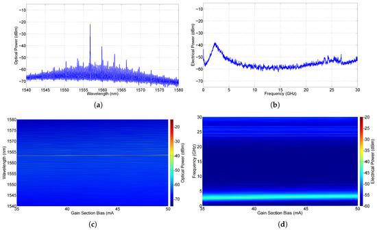
Figure 2.
(a) the optical spectrum and (b) the electrical spectrum of the free-running S-SFP. Colour intensity plots of (c) the optical spectra and (d) the electrical spectra from the free-running M-SFP.
3. Off-Chip Experimental Setup
A schematic of the experimental setup is shown in Figure 3 [11,16,17]. The output of each SFP was fibre coupled using a lensed fibre. The output of the M-SFP was guided through single mode fibre and a polarisation controller to port 1 of an optical circulator, which provided a greater than 40 dB isolation between its ports. Port 2 of the circulator was coupled to the output of the S-SFP. The signal from port 3 of the circulator was split in three and fed to an OSA (Yokogawa AQ6370D; Resolution—0.045 nm), an ESA (HP 8565EC; Bandwidth—50 GHz) and a HSO (Tektronix TDS6154C); Bandwidth—15 GHz and Sampling rate—40 GS/s), in order to investigate the optical and electrical characteristics of the signal. The signal was amplified using an erbium doped fibre amplifier (EDFA) before going to the photodetectors (PD) (Finisar XPRV2022; Bandwidth—33 GHz for the ESA and Finisar XPDV2120; Bandwidth—50 GHz for the HSO) to obtain a strong signal on the ESA and HSO.
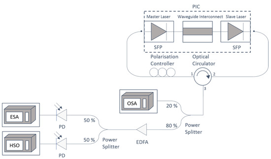
Figure 3.
Experimental setup showing the off-chip coupling scheme between two lasers on the same integrated device. The waveguide interconnect linking both lasers was reverse biased to V which removed any coupling between the lasers on-chip. Instead, light from the master laser was coupled into the slave laser via a polarisation controller and optical circulator.
4. Off-Chip Injection Locking
The M-SFP was swept across resonance with one of the side modes of the S-SFP by varying its gain section bias, between 35 mA and 50 mA. At each bias step, the output of the S-SFP was recorded on the OSA, ESA and HSO. The OSA traces were concatenated to create the colour intensity plot in Figure 4a with master gain section (M-GS) bias on the x-axis, wavelength on the y-axis and the colour bar represents optical power. Similarly, the colour intensity plot of the ESA traces is shown in Figure 4b and the colour intensity plot of the HSO traces in Figure 4c. The FFT of the HSO traces in Figure 4c was performed in Matlab (R2012a) and the result is seen in Figure 4d. The FFT is nearly identical to the ESA traces in Figure 4b, but, due to the sampling rate of the HSO, the FFT does not give as high resolution or high frequency as the ESA. The FFT of the HSO traces does not give any new information but verifies the results obtained on the ESA. The data from the HSO are also important in the setup because it allows dynamics that are not seen on the ESA to be investigated.
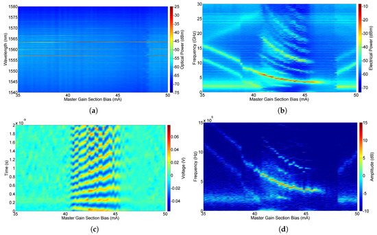
Figure 4.
Colour intensity plots of (a) the optical spectra, (b) the electrical spectra, (c) the time traces and (d) the FFT (Fast Fourier Transform) of the time traces from the S-SFP for the off-chip coupling scheme.
The main mode of the free-running S-SFP had a wavelength of approximately 1557 nm and the side mode chosen for locking was at approximately 1563 nm, both visible in red in Figure 4a. The M-GS bias was swept from 35 mA to 50 mA, thus sweeping the M-SFP across resonance with the S-SFP. The total sweep was approximately 0.285 nm.
For each M-GS bias, the data from all equipment was analysed to determine the characteristics of the interaction taking place. For example, for a M-GS bias below 40.6 mA, low frequency ESA peaks are associated with relaxation oscillations, while higher frequency ESA peaks are caused by the beating of lasing modes from both lasers. Between 40.6 and 46.4 mA, strong beating is observed between the master and slave lasers. The S-SFP is injection locked for M-GS biases between 46.4 and 48.2 mA, and then, for higher biases, the S-SFP goes out of locking and beating can again be seen from the ESA and HSO data.
Figure 5 is a summary of the types of behaviour obtained during injection locking as a function of M-GS bias. These types of behaviour; (i) beating, (ii) nonlinear interactions (NLI) and (iii) locked, are similar to those presented in [11].
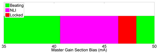
Figure 5.
Summary of the types of behaviour obtained during injection locking as a function of the master gain section bias, for the off-chip coupling regime.
The figures in Appendix A.1 provide characteristic examples of the data from the OSA, ESA and HSO demonstrating these types of behaviours. Figure A1 is an example of beating behaviour, where the lasers are beating together and the detuning between the lasers can be seen on the ESA, but the lasers do not interact. At smaller detunings where the lasers beat strongly together, nonlinear interactions occur as is seen in Figure A2. Finally, injection locking is seen in Figure A3, where the S-SFP is injection locked to the M-SFP and hence lases at the wavelength of the M-SFP.
Now that the known regimes of injection locking a master/slave system have been demonstrated for the off-chip coupling regime, we will investigate the on-chip coupling regime, where there is feedback between the lasers.
5. On-Chip Injection Locking
In order to confirm that this method for detecting injection locking works for the on-chip coupling regime where there is feedback between the lasers, the circulator was removed and the VOA was forward biased allowing the lasers to interact on-chip. A schematic of the experimental setup for the on-chip coupling regime is shown in Figure 6 [11]. The circulator was removed and the VOA was forward biased to 1.091 V, allowing the lasers to interact on-chip. An optical switch enabled the output of both lasers to be examined on the ESA, OSA and HSO, as described previously.
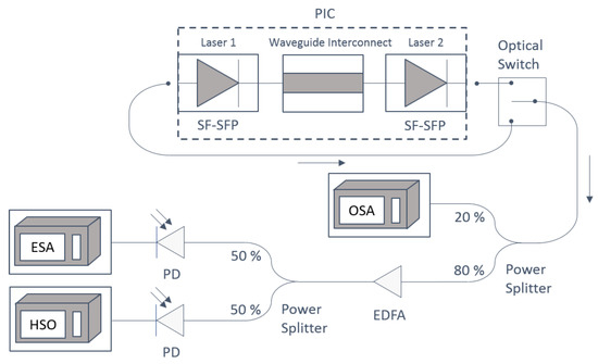
Figure 6.
Experimental setup showing the on-chip coupling scheme between two lasers on the same integrated device. The waveguide interconnect linking both lasers was forward biased to 1.091 V, which allowed the lasers to interact on-chip. An optical switch enabled the output of both lasers to be examined.
The experiment was repeated, but the removal of the circulator and subsequent mutual coupling meant that the output of both lasers needed to be recorded. Colour intensity plots of the OSA, ESA and HSO traces from the M-SFP and S-SFP are shown in Figure 7. The types of behaviour observed were similar to the off-chip coupling regime, Figure 4; however, some new types of behaviour generated by the feedback between the lasers were also observed.
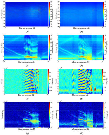
Figure 7.
Output of the master and slave lasers (on-chip coupling scheme). (a) OSA traces from the master laser, (b) OSA traces from the slave laser, (c) ESA traces from the master laser, (d) ESA traces from the slave laser, (e) HSO traces from the master laser, (f) HSO traces from the slave laser, (g) FFT of the HSO traces from the master laser, and (h) FFT of the HSO traces from the slave laser.
When the M-GS bias is below 40 mA, the lasers are coupled but not interacting and the expected beating between the different lasing modes are seen with the relaxation oscillation peak. At 40 mA, there is significant beating between a suppressed mode of the master and a dominant mode of the slave at 1.9 GHz. The corresponding ESA signal is approximately 27.5 dB stronger in the slave than the master, and can only be seen in the HSO trace of the slave. This will be later referred to as asymmetric beating.
For M-GS bias between 41 and 45 mA, the expected nonlinear interaction occurs between the unlocked lasers. The HSO signal from both lasers forms a clear sinusoidal trace. At 45 mA, while the lasers are still unlocked and beating, the HSO trace shows irregular dynamics with large changes in the amplitude of the signal. In addition, longer wavelength modes have appeared in both master and slave lasers near 1567 nm. These longer modes are not due to a temperature increase in the laser; high resolution OSA data showed that there was no change in the gain peak of the laser from 1563 nm.
At a M-GS bias of 46.6 mA, the interaction changes. Both lasers are now operating highly multi-mode. The HSO trace of the master and slave appear completely patternless, a behaviour that will be referred to as aperiodic. At 47.4 mA, the lasers are locked albeit at a longer wavelength of 1566.5 nm. This shift toward longer wavelength is unexpected and as yet unexplained. At higher M-GS biases, the lasers return to free-running states.
This experiment was repeated for multiple VOA biases between 1.08 and 1.13 V. Figure 8 provides a summary of the types of behaviour obtained from the M-SFP and the S-SFP during injection locking as a function of M-GS bias and VOA bias. The dashed line across the graphs represents the data set discussed above for a VOA bias of 1.091 V. The three types of behaviour identified for the off-chip coupling regime; (i) beating, (ii) nonlinear interactions and (iii) locked, are also present for the on-chip coupling regime and new types of behaviour have been generated due to the feedback between the lasers. Irregular dynamics and aperiodic behaviour are exhibited by both the M-SFP and S-SFP, while asymmetric beating and pulsing were exhibited by the S-SFP alone.
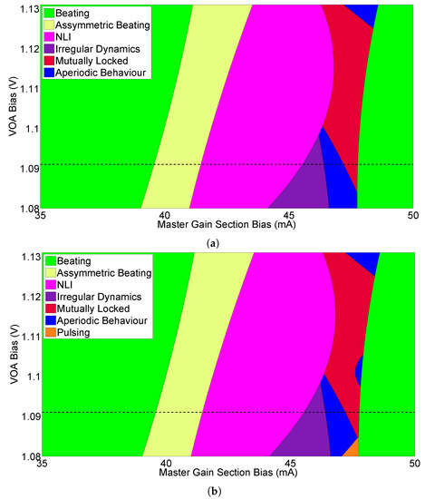
Figure 8.
Summary of the types of behaviour obtained from (a) the M-SFP and (b) the S-SFP during injection locking as a function of M-GS bias, for the on-chip coupling regime.
The figures in Appendix A.2 provide characteristic examples of these new types of behaviours; Figure A4 is an example of asymmetric beating, Figure A5 of irregular dynamics, Figure A6 of aperiodic behaviour and Figure A7 of mutual injection locking. The biggest difference between the off and on-chip coupling regimes is that for the off-chip coupling regime when the lasers injection lock, the S-SFP locks to the M-SFP and both lasers then lase at the wavelength of the M-SFP. However, for the on-chip coupling regime when the lasers mutually injection lock, both lasers lock to a higher mode. The locking width is also narrower for the on-chip coupling regime due to the regions of irregular beating and aperiodic behaviour before the locking region. However, this width can be increased by increasing the VOA bias.
Reducing the VOA bias to 1.081 V reduces the coupling between the lasers therefore preventing the lasers from injection locking. Figure 8 shows that, at the M-GS biases where injection locking would be expected, the lasers behave aperiodically. However, there is a small region (M-GS = 47.2–48 mA) where the time traces of the S-SFP show pulsing behaviour, Figure A8. The time trace of the S-SFP, Figure A8c, shows pulsing at ∼0.94 GHz and a corresponding beat note is observed in the electrical spectrum. No beating was seen in the electrical spectrum of the M-SFP. The signal obtained on the HSO (Figure A8c) has a frequency of 0.94 GHz, but it is not a sinusoidal signal. Without the HSO data, it may have been assumed that the beating between the lasers was sinusoidal. This illustrates how important the time traces are to fully understand the interaction between the lasers. The modes in the optical spectrum of the S-SFP are not smooth but have many little peaks close together, as is shown in the inserts of Figure A8b.
Each piece of equipment provides results that are valuable when investigating the injection locking of the lasers. Both the ESA and the HSO can be used to identify the locking region, regions of aperiodic behaviour, and regions of beating between the free-running lasers. However, only the HSO provides time trace information, which is valuable when investigating aperiodic regimes. The time traces can be compared with theoretical models to determine the type of dynamical behaviour between the lasers. The ESA is more sensitive and has a higher bandwidth than the HSO, which is useful to detect high frequency beating between the lasers. While the ESA and HSO show the beating and hence the detuning between the lasers, only the OSA provides information on the wavelength and optical behaviour of the lasers, e.g., the wavelength at which the lasers lase when injection locked.
6. Conclusions
The on and off-chip locking between two integrated lasers have been measured and compared. The off-chip injection locking of two integrated SF-SFP lasers was used to demonstrate an effective method to detect injection locking using an OSA, an ESA and a HSO. This same technique was then used to measure the on-chip injection locking of the two integrated SF-SFP lasers. The on-chip measurements showed additional types of behaviour generated by the feedback between the lasers that were not seen in the off-chip coupling region. These include aperiodic and pulsating behaviour, as well as locking beyond the gain peak at a red shifted mode of the lasers. The gain peak has not shifted. Instead, the laser interactions result in a suppression of the mode near the gain peak and the lasing at a mode red shifted far beyond the gain peak. An objective baseline for injection locking has been obtained, which will be used in future comparisons between mutually injection locked lasers on-chip.
Author Contributions
A.H.P.: Designed PIC, performed the injection locking experiments, analysed the results and wrote the paper. L.C. and M.D.: Fabrication of PIC. F.H.P.: Funding acquisition, conceptualisation of the project and reviewing/editing of the manuscript.
Funding
This research was funded by the Science Foundation Ireland under grant SFI 13/IA/1960.
Acknowledgments
The authors would like to thank the reviewers for their valuable suggestions.
Conflicts of Interest
The authors declare no conflict of interest.
Appendix A
Appendix A.1. Off-Chip Figures
This section contains characteristic optical spectra, electrical spectra and time traces from the output of the S-SFP obtained for the off-chip coupling regime. These plots are cross-sections of the colour intensity plots in Figure 4. The figures describe the three types of behaviours discussed previously in Section 4; (i) Beating—Figure A1, where the lasers are beating together and the detuning between the lasers can be seen on the ESA, but the lasers do not interact, (ii) Nonlinear interactions—Figure A2, where the detuning between the lasers is small enough that they beat strongly together, and (iii) Injection locking—Figure A3, where the S-SFP is injection locked to the M-SFP and hence lases at the wavelength of the M-SFP.

Figure A1.
(a) the optical spectrum and (b) the electrical spectrum of the S-SFP for the off-chip coupling
scheme, for a M-GS = 35 mA. The lasers beat together and are ~16 GHz apart.

Figure A2.
(a) the optical spectrum and (b) the time trace of the S-SFP for the off-chip coupling scheme,
for a M-GS = 45 mA. The lasers interact nonlinearly and are ~3.6 GHz apart. In addition, 3.6 GHz
(~0.03 nm) is less than the resolution of the OSA; therefore, the main mode of the M-SFP and the side
mode of the S-SFP have merged into a single peak in the optical spectrum.

Figure A3.
(a) the optical spectrum and (b) the electrical spectrum of the S-SFP for the off-chip coupling
scheme, for a M-GS = 47.8 mA. The lasers are injection locked.
Appendix A.2. On-Chip Figures
This section contains characteristic optical spectra, electrical spectra and time traces from the output of the S-SFP obtained for the on-chip coupling regime. These plots are cross-sections of the colour intensity plots in Figure 7. The figures describe the five new types of behaviours generated by the feedback between the lasers discussed previously in Section 5; (i) Asymmetric beating—Figure A4, where the lasers beat together and the S-SFP exhibits strong low frequency beating, (ii) Irregular dynamics—Figure A5, where the lasers beat together, but the amplitude of the beating is not uniform but irregular, (iii) Aperiodic behaviour—Figure A6, where the lasers beat together aperiodically, (iv) Pulsing—Figure A8, where the lasers beat together aperiodically but the S-SFP exhibits pulsing behaviour and (v) Mutual injection locking—Figure A7, where the lasers are mutually injection locked and both lasers have mode hopped to a higher mode (∼1566.5 nm).
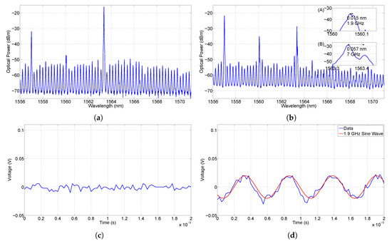
Figure A4.
(a,b) the optical spectra and (c,d) the time traces of the M-SFP and S-SFP, respectively, for the on-chip coupling scheme, for a VOA bias = 1.091 V and a M-GS = 40 mA. The lasers beat
together asymmetrically and are ~7 GHz apart.
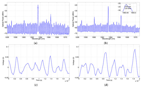
Figure A5.
(a,b) the optical spectra and (c,d) the time traces of the M-SFP and S-SFP, respectively,
for the on-chip coupling scheme, for a VOA bias = 1.091 V and a M-GS = 45 mA. The lasers beat
together and are ~3.8 GHz apart. The beating between the lasers is not uniform but irregular.
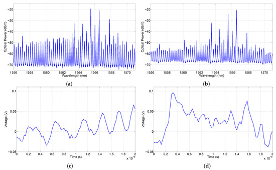
Figure A6.
(a,b) the optical spectra and (c,d) the time traces of the M-SFP and S-SFP, respectively,
for the on-chip coupling scheme, for a VOA bias = 1.091 V and a M-GS = 46.6 mA. The lasers beat
together aperiodically and are ~1.6 GHz apart.
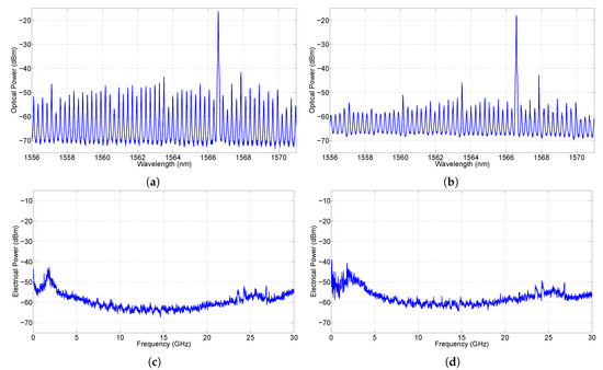
Figure A7.
(a,b) the optical spectra and (c,d) the electrical spectra of the M-SFP and S-SFP, respectively, for the on-chip coupling scheme, for a VOA bias = 1.091 V and a M-GS = 47.4 mA. The lasers are
mutually injection locked. Both lasers have mode hopped and now lase at ~1566.5 nm.
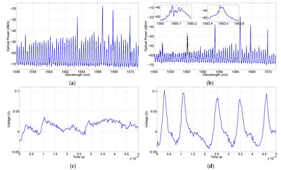
Figure A8.
(a,b) the optical spectra and (c,d) the time traces of the M-SFP and S-SFP, respectively,
for the on-chip coupling scheme, for a VOA bias = 1.081 V and a M-GS = 47.2 mA. The lasers beat
together aperiodically and are ~0.94 GHz apart. The S-SFP exhibits pulsing behaviour.
References
- Lang, R. Injection locking properties of a semiconductor laser. IEEE J. Quantum Electron. 1982, 18, 976–983. [Google Scholar] [CrossRef]
- Cotter, W.; Goulding, D.; Roycroft, B.; O’Callaghan, J.; Corbett, B.; Peters, F.H.; O’Callaghan, J.; Corbett, B.; Peters, F.H. Investigation of active filter using injection-locked slotted Fabry–Perot semiconductor laser. Appl. Opt. 2012, 51, 7357–7361. [Google Scholar] [CrossRef] [PubMed]
- Ellis, A.; Gunning, F. Spectral density enhancement using coherent WDM. IEEE Photonics Technol. Lett. 2005, 17, 504–506. [Google Scholar] [CrossRef]
- Morrissey, P.E.; Cotter, W.; O’Callaghan, J.; Yang, H.; Roycroft, B.; Goulding, D.; Corbett, B.; Peters, F.H. Multiple coherent outputs from single growth monolithically integrated injection locked tunable lasers. In Proceedings of the International Conference on Indium Phosphide and Related Materials, Santa Barbara, CA, USA, 27–30 August 2012; pp. 281–284. [Google Scholar] [CrossRef]
- Winzer, P.J.; Essiambre, R.J. Advanced modulation formats for high-capacity optical transport networks. J. Lightwave Technol. 2006. [Google Scholar] [CrossRef]
- van Tartwijk, G.H.M.; Lenstra, D. Semiconductor lasers with optical injection and feedback. Quantum Semiclass. Opt. J. Eur. Opt. Soc. Part B 1995, 7, 87–143. [Google Scholar] [CrossRef]
- Wieczorek, S.; Krauskopf, B.; Lenstra, D. Unifying view of bifurcations in a semiconductor laser subject to optical injection. Opt. Commun. 1999, 172, 279–295. [Google Scholar] [CrossRef]
- Hegarty, S.P.; Goulding, D.; Kelleher, B.; Huyet, G.; Todaro, M.T.; Salhi, A.; Passaseo, A.; De Vittorio, M. Phase-locked mutually coupled 1.3 μm quantum-dot lasers. Opt. Lett. 2007, 32, 3245. [Google Scholar] [CrossRef] [PubMed]
- Fujiwara, N.; Takiguchi, Y.; Ohtsubo, J. Observation of the synchronization of chaos in mutually injected vertical-cavity surface-emitting semiconductor lasers. Opt. Lett. 2003, 28, 1677. [Google Scholar] [CrossRef] [PubMed]
- Vicente, R.; Tang, S.; Mulet, J.; Mirasso, C.R.; Liu, J.M. Synchronization properties of two self-oscillating semiconductor lasers subject to delayed optoelectronic mutual coupling. PHysical Rev. E Stat. Nonlinear Soft Matter Phys. 2006, 73, 047201. [Google Scholar] [CrossRef] [PubMed]
- Morrissey, P.E.; Cotter, W.; Goulding, D.; Kelleher, B.; Osborne, S.; Yang, H.; O’Callaghan, J.; Roycroft, B.; Corbett, B.; Peters, F.H. On-chip optical phase locking of single growth monolithically integrated Slotted Fabry Perot lasers. Opt. Express 2013, 21, 17315–17323. [Google Scholar] [CrossRef] [PubMed]
- Byrne, D.C.; Engelstaedter, J.P.; Guo, W.H.; Lu, Q.Y.; Corbett, B.; Roycroft, B.; O’Callaghan, J.; Peters, F.H.; Donegan, J.F. Discretely tunable semiconductor lasers suitable for photonic integration. IEEE J. Sel. Top. Quantum Electron. 2009, 15, 482–487. [Google Scholar] [CrossRef]
- Alexander, J.K.; Morrissey, P.E.; Yang, H.; Yang, M.; Marraccini, P.J.; Corbett, B.; Peters, F.H. Monolithically integrated low linewidth comb source using gain switched slotted Fabry–Perot lasers. Opt. Express 2016, 24, 7960–7965. [Google Scholar] [CrossRef] [PubMed]
- Dernaika, M.; Caro, L.; Kelly, N.P.; Alexander, J.K.; Dubois, F.; Morrissey, P.E.; Peters, F.H. Deeply Etched Inner-Cavity Pit Reflector. IEEE Photonics J. 2017, 9, 1–8. [Google Scholar] [CrossRef]
- Kelly, N.P.; Dernaika, M.; Caro, L.; Morrissey, P.E.; Perrott, A.H.; Alexander, J.K.; Peters, F.H. Regrowth-Free Single Mode Laser Based on Dual Port Multimode Interference Reflector. IEEE Photonics Technol. Lett. 2017, 29, 279–282. [Google Scholar] [CrossRef]
- Hurtado, A.; Quirce, A.; Valle, A.; Pesquera, L.; Adams, M.J. Nonlinear dynamics induced by parallel and orthogonal optical injection in 1550 nm Vertical-Cavity Surface-Emitting Lasers (VCSELs). Opt. Express 2010, 18, 9423–9428. [Google Scholar] [CrossRef] [PubMed]
- Balakier, K.; Fice, M.J.; van Dijk, F.; Kervella, G.; Carpintero, G.; Seeds, A.J.; Renaud, C.C. Optical injection locking of monolithically integrated photonic source for generation of high purity signals above 100 GHz. Opt. Express 2014, 22, 29404. [Google Scholar] [CrossRef] [PubMed]
© 2019 by the authors. Licensee MDPI, Basel, Switzerland. This article is an open access article distributed under the terms and conditions of the Creative Commons Attribution (CC BY) license (http://creativecommons.org/licenses/by/4.0/).