Article

Refractive Index Sensor Based on Twisted Tapered Plastic Optical Fibers

1
Photonics Research Centre, Guilin University of Electronic Technology, Guilin 541004, China
2
Guangxi Key Laboratory of Optoelectronic Information Processing, Guilin University of Electronic Technology, Guilin 541004, China
3
State Key Laboratory on Integrated Optoelectronics, College of Electronic Science and Engineering, Jilin University, Changchun 130012, China
*
Authors to whom correspondence should be addressed.
Photonics 2019, 6(2), 40; https://doi.org/10.3390/photonics6020040
Submission received: 11 February 2019 / Revised: 31 March 2019 / Accepted: 3 April 2019 / Published: 9 April 2019
(This article belongs to the Special Issue Polymer Optical Fibre)

Abstract

:
We proposed a refractive index (RI) sensor employing two twisted tapered plastic optical fibers (POFs). The tapered POFs were fabricated by a heating and drawing method and were twisted around each other to form a coupled structure. The sensor consisted of two input ports, a twisted region, and two output ports. The tapered POF could make the light couple from one POF to the other easily. The twisted tapered POFs could constitute a self-referencing sensor, and by monitoring the changes of the coupling ratio, the variations of the external medium RIs could be measured. The RI sensing performances for the sensors with different fiber diameters and twisted region lengths were studied. The sensitivities of 1700%/RIU and −3496%/RIU in the RI ranges of 1.37–1.41 and 1.41–1.44 were obtained, respectively. The sensor is a low-cost solution for liquid RI measurement, which has the features of simple structure and easy fabrication.

1. Introduction

Refractive index (RI) sensing plays an important role in many applications, such as biochemical analysis, food industry, environment monitoring, and so on. Optical-fiber-based RI sensors have the advantages of immunity to electromagnetic interference, compact size, and remote sensing ability. To date, many kinds of optical fiber RI sensors have been proposed. For example, RI sensors based on tilted fiber Bragg gratings [1], long period fiber gratings [2], multi-mode interference [3], etc. However, these sensors usually require complicated fabrication processes and employ wavelength modulation methods which require expensive demodulation devices in practical applications.
Recently, sensors based on plastic optical fibers (POFs) have attracted a great deal of attention, which may provide a low-cost and disposable solution for liquid RI detection [4]. Compared with the glass counterparts, POFs-based RI sensors have the features of better flexibility, easy handling, and operation in the visible region. In order to enhance the RI sensitivity, the POFs should be modified. Tapering [5,6,7], side-polishing [8,9,10,11], and making a hole [12,13,14] are the common structural modified methods. Generally, POFs based RI sensors are more suitable for intensity modulation schemes due to their multimode characteristic. However, intensity-modulated measurement systems are susceptible to undesirable perturbations.
The optical fiber coupler is an important device which also has many potential applications in sensing fields. Montero et al. [15] proposed a side-polished POFs coupler for liquid detection. The coupled structured POFs were used as a self-referencing sensing device, which could compensate the undesirable perturbations, but the coupled region was fixed by glue, which could introduce losses of absorption and radiation. Many coupled structured optical fibers sensors have been proposed, involving both glass optical fibers and POFs. References [16,17] presented a micro-glass fiber coupler for RI sensing, but the microfiber is very fragile, and the test equipment is expensive. Hou et al. [18] proposed a twisted ordinary commercial bare POF for liquid level detection, but the coupling efficiency of the ordinary bare fibers was very small, and the output signal was so weak that the signal-to-noise ratio was very low. Zhu et al. [19] presented twisted polymer nanowires for RI sensing, but it was difficult to integrate the polymer nanowire device with the fiber system and the insertion loss was relatively large. To our knowledge, twisted tapered POFs for RI sensing have not been studied in previous works, which can overcome these problems.
In this paper, we demonstrate an RI sensor based on twisted tapered POFs. The tapered POFs were fabricated by a heating and drawing method. The thinned POFs could make the light couple from one POF to the other easily. The changes of external medium RI in the twisted region could be detected by monitoring the coupling ratio (K). Because the two fiber output ends share the same light source, the power fluctuations could be diminished, so it was used as a self-referencing sensor. Besides, the sensor could detect RIs higher than that of the fiber cladding and has the advantages of low cost and easy fabrication.

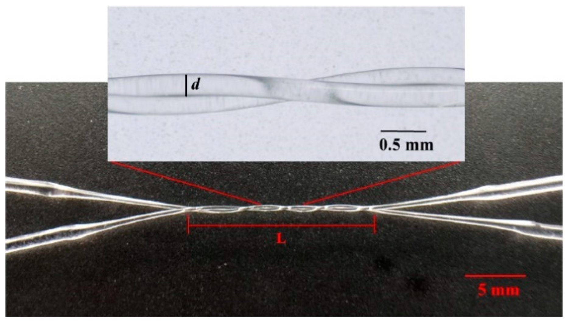
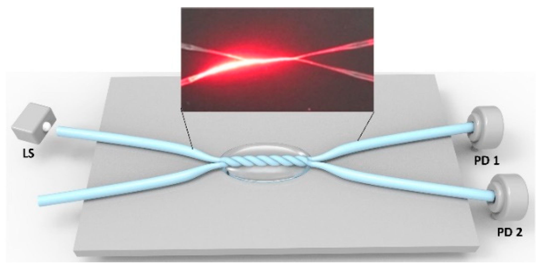
2. Fabrication and Operation Principle

The fiber used in this study was a commercial step-index POF (Jiangxi Dashing POF Co., Ltd.) with a PMMA core material and a fluorinated polymer cladding material. The core diameter was 980 μm with an RI of 1.49, while the cladding thickness was 10 μm with a lower RI of 1.41. The tapered POF was fabricated by a heating and drawing process [5]. The POF was placed about 1 cm over the soldering iron and fixed by two translation stages. The soldering iron was heated to about 450 °C. The POF was drawn with a suitable velocity when it was heated to a softening temperature. After the drawing process, a fused-biconical tapered POF was formed, which consisted of a long and uniform thinned POF and two tapered transition regions. The biconical tapered POF with different shapes and properties could be fabricated by adjusting the heating temperature, heating time, and drawing speed, and it was measured by a microscope. As we know that the fraction of the evanescent field will increase as the fiber diameter decreases, this enables the easy energy exchange between the two fibers. Thus, tapered POFs with different diameters were studied in our experiment to compare their RI sensitivities.
The fabrication method in [19] was used to prepare the twisted structure, two tapered POFs were fixed in parallel on the supports, keeping one support fixed and the other one rotated around. The distance between the parallel tapered POFs was less than 1 cm to avoid a large extra axial strain. The coupled structure was flexible, as the twisted structure could be changed by using the tapered POFs with different diameters, and the twisted region length L could be changed by adjusting the number of twisted turns. During the twisting process, a light was coupled to the fiber and the powers of two output ports were monitored in order to get the desired coupling ratio. After fabricating the twisted tapered POFs, the two input and two output ports of the POFs were fixed on a PTFE flat panel (Teflon) substrate by silicon sealant. The RI of the substrate was relatively low to diminish the material’s absorption of the transmitted light. Figure 1 shows a photo of the twisted tapered POFs.
When the POF was tapered, the higher-order core modes were forced into the cladding layer, then the radiation modes and cladding modes were generated. The radiation modes leak out of the fiber core and cladding, going into the external medium. The cladding modes were bounded by the cladding–medium interface due to the total internal reflection, and the evanescent field penetrated into the external medium. The penetration depth d p of the evanescent field is expressed as:
d p = λ 2 π n c l 2 s i n 2 θ n e x 2 ,
where λ is the wavelength of transmitted light, θ is the incident angle at the cladding–medium interface, and ncl and nex are the RIs of the cladding and external medium, respectively. Due to the effect of frustrated total internal reflection [18], an energy coupling may occur between the two twisted tapered POFs. When the RI of the external medium of the coupled region changes, the mode profile of the tapered POFs will be altered, leading to changes in the coupling property. Therefore, by monitoring the coupling ratio (K), the RIs of measured liquids could be obtained.

3. Results and Discussion

3.1. Experiment Setup

In order to evaluate the spectral characteristics of the twisted tapered POFs, a broadband light source (DH-2000, Ocean Optics) with operating wavelength from 215 to 2000 nm and a spectrometer (NOVA, Ideaoptics) were used. The light was guided into one of the twisted fibers, and the spectra for the twisted region in air, water, and glycerin solution were recorded. The fiber with the input light was called the active fiber, and the other one was called the passive fiber. Twisted tapered POFs with the active fiber diameter of 100 μm and passive fiber diameter of 200 μm were tested. The results are shown in Figure 2; it was found that the transmission loss (the integration time of the spectrometer was set at 10 ms) was less obvious between the twisted tapered active POF and the non-twisted one, but it decreased when the twisted region was surrounded by water or glycerin solution. For the passive fiber, it was found that there was a very large transmission loss (the integration time of the spectrometer was set at 20 ms) when the twisted region was surrounded by water, but when the medium was changed to glycerin solution (RI of 1.39), the loss became smaller. In order to evaluate the sensing performance of the probe, a laser diode (TLS001-635, Thorlabs) with the wavelength of 635 nm and two photodiodes (S120, Thorlabs) with the responsivity of 0.41 A/W at 635 nm were used.
A schematic diagram of the experiment setup is shown in Figure 3. As shown in the figure, the twisted tapered POFs were fixed on a substrate. The light source was launched into one of the input ports, and two photodiodes with a resolution of 1 nW were used to detect the light signals at the two output ends. The glycerin–water solutions with different volume concentrations (different RIs of external media) were prepared as the measured liquids. The RIs of the solutions were measured by an Abbe refractometer and described by the relation n = 1.33 + 0.13C, where C is the volume concentration of the glycerin at 20 °C. The glycerin–water solutions were dropped around the twisted region as the external media with different RIs. For each measured liquid RI, the experiment was carried out five times repeatedly, and the averaged values were calculated. After each measurement, the sensing area was washed with deionized water and dried for the next measurement. The experiment was carried out at a room temperature of 20 °C.

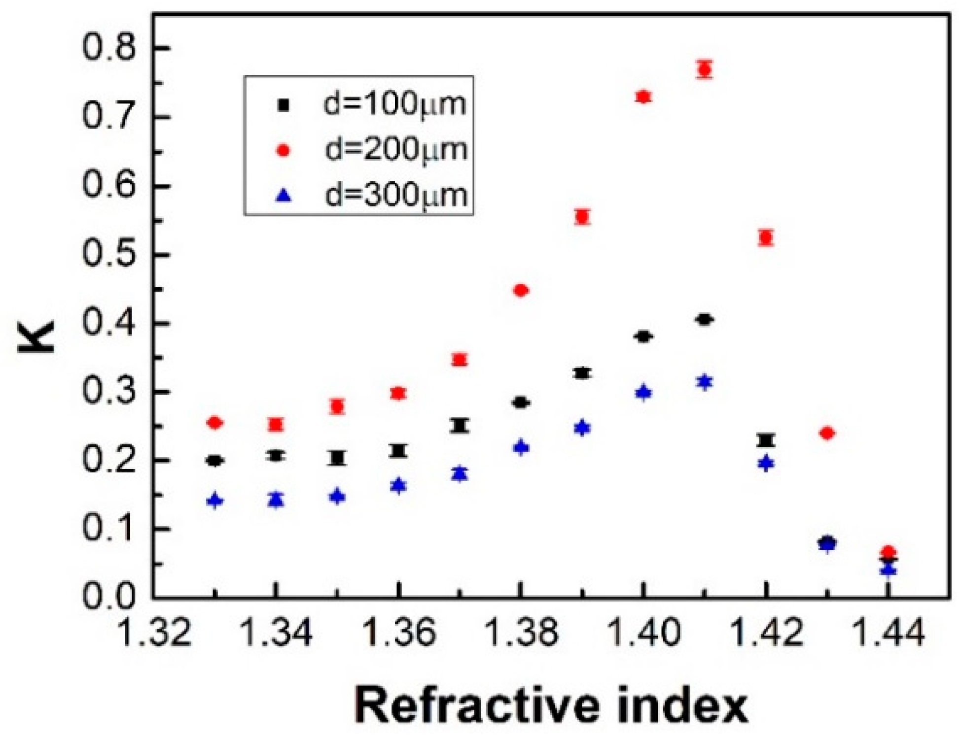
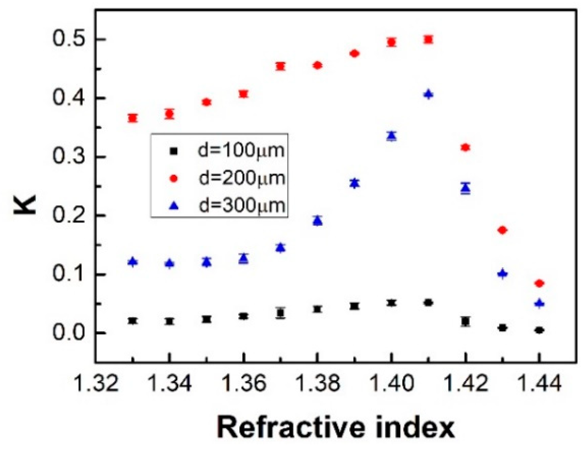
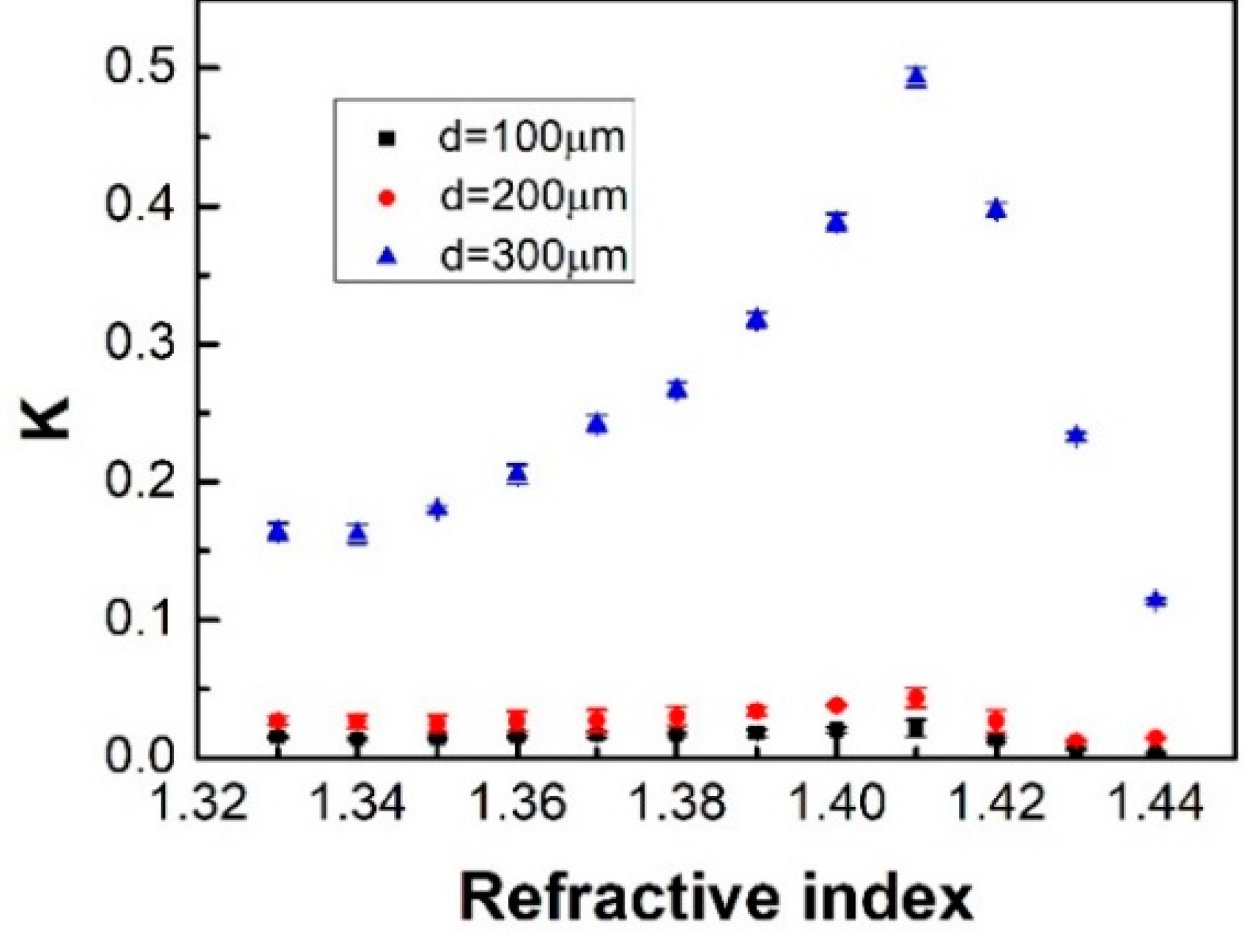
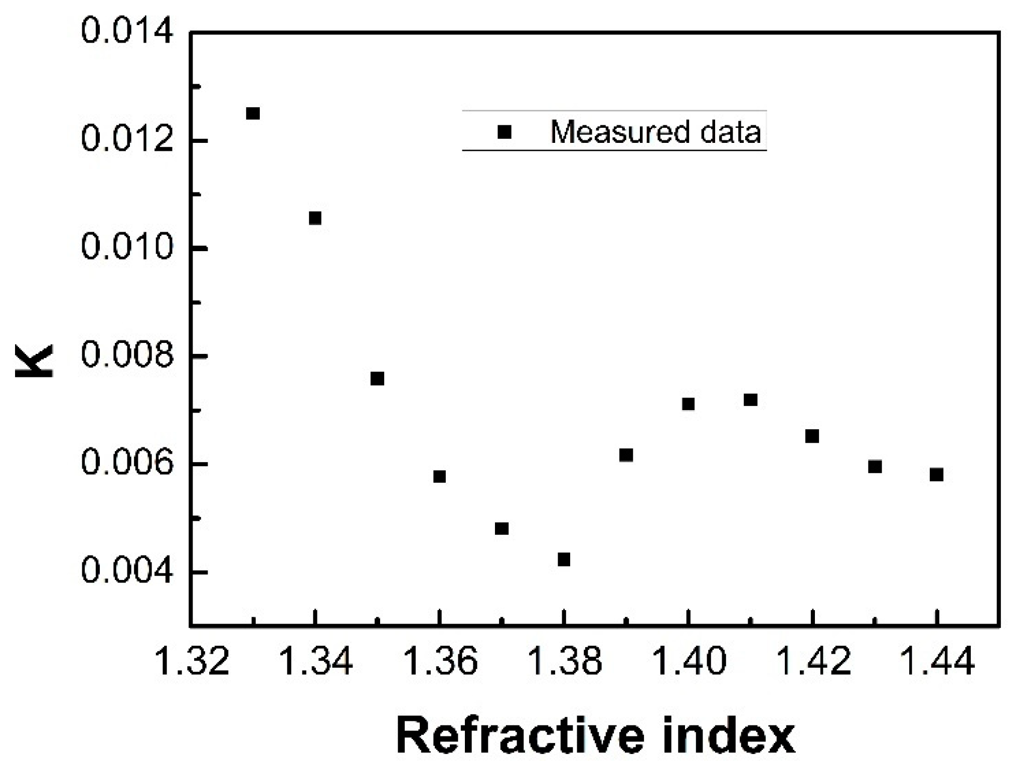
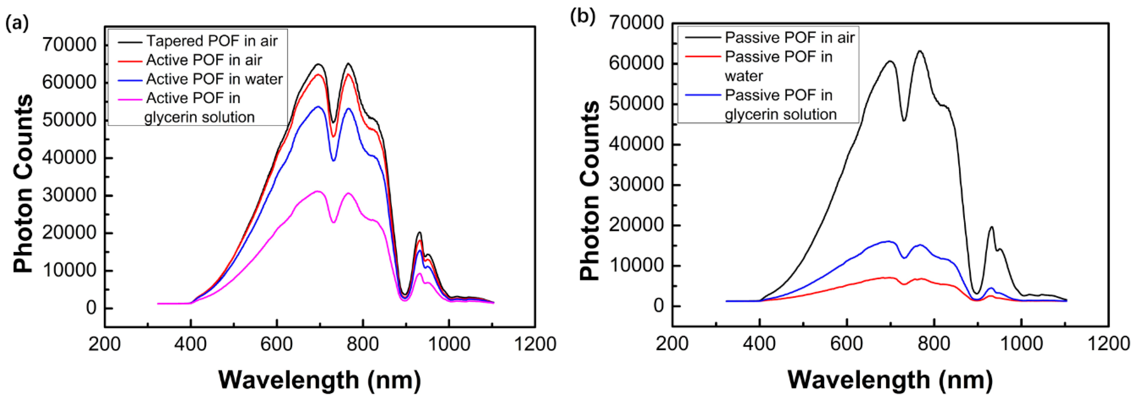
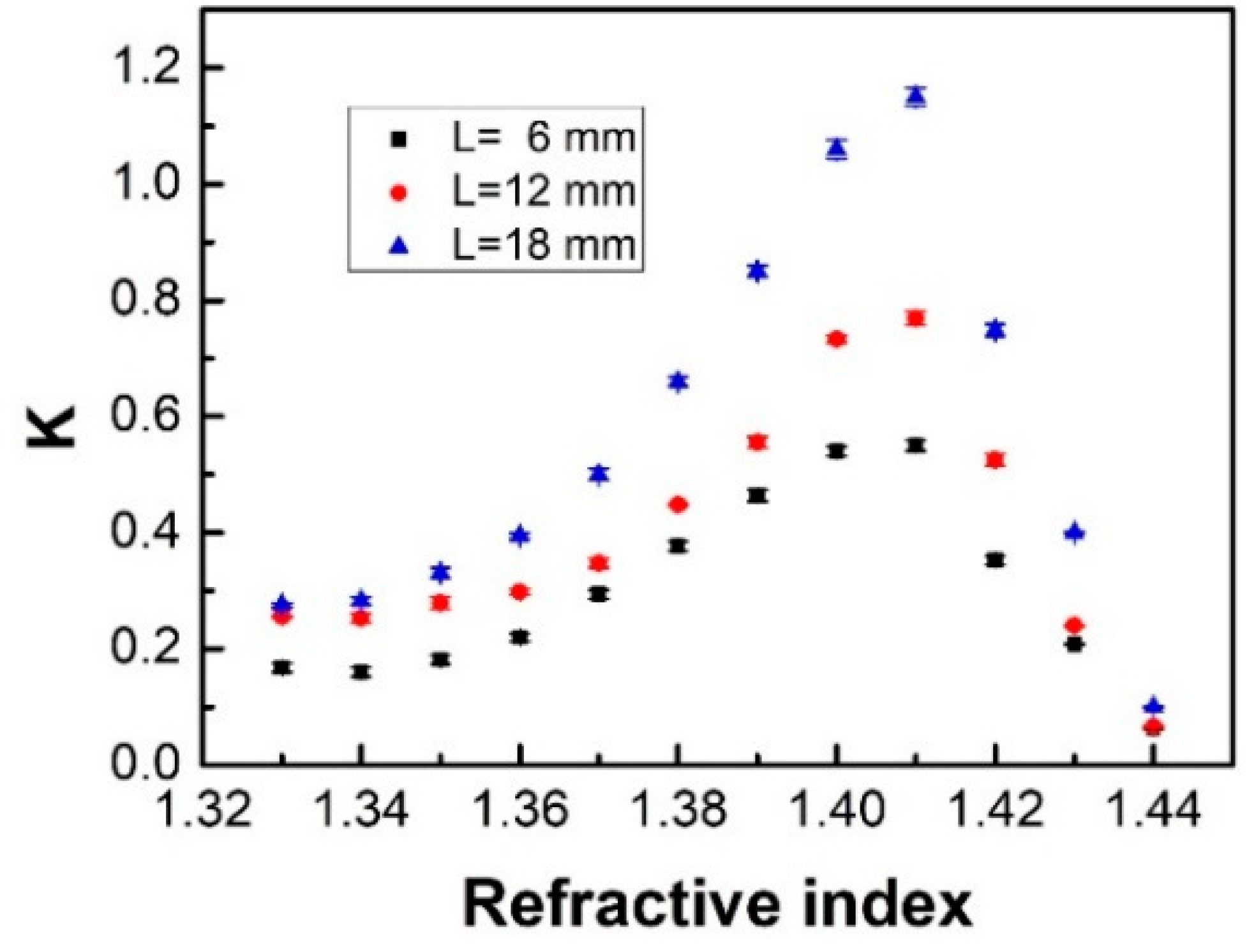
3.2. Experiment Results and Discussion

Figure 4 shows the RI sensing performances for the sensors with active fiber diameter of 100 μm, while the passive fibers’ diameters were of 100, 200, and 300 μm, respectively. The twisted region length was 12 mm. The coupling ratio K = PpasPact, where Ppas and Pact were the average sensor outputs of passive and active fiber, respectively. Error bars are given for all measured data. The sensitivity of the investigated sensor was given as S = ∆K∆n × 100%, where ΔK is the change of the coupling ratio and Δn is the change of measured liquid RI. As shown in Figure 4, it was found that the K displayed a non-monotonic change with the external medium RIs. When the liquid RI was smaller than 1.41, the cladding RI of the POF, the coupling ratio K increased with the increased nex, but when the nex was larger than 1.41, K decreased. This may be because that when nex was equal to the fiber cladding, all the cladding modes were no longer guided and transformed to the radiation modes, which led to a decreased K. This indicates the proposed sensor could detect a liquid RI higher than that of the fiber cladding, and the RI sensing range can be divided into two parts with the RI point of 1.41. It was also found that the sensor had a linear response in the RI ranges of 1.37–1.41 and 1.41–1.44. The sensor had the highest sensitivity when the passive fiber diameter was 200 μm. The sensitivity results from Figure 4 are shown in Table 1.
Figure 5 shows the experiment results for the sensors with the active fiber diameter of 200 μm, while the passive fibers’ diameters were 100, 200, and 300 μm, respectively, and the twisted region length was 12 mm. It was found that the sensitivity was the lowest when the passive fiber diameter was 100 μm. The sensitivity results from Figure 5 are shown in Table 2.
Figure 6 shows the RI sensing performances for the sensors with the active fiber diameter of 300 μm, passive fiber diameters of 100, 200, and 300 μm, and twisted region length of 12 mm. It was found the sensitivity was relatively low for sensors with passive fiber diameter of 100 μm or 200 μm. The sensitivity results from Figure 6 are shown in Table 3.
From the experimental results above, it was found that the sensor had a better sensitivity when the diameter of the active fiber was smaller than that of the passive one, and the situation was the opposite otherwise. This may be because an active fiber with a small diameter would introduce more evanescent field and make more light energy leak out of fiber; on the other hand, a passive fiber with a large diameter has a larger surface area, which may receive more energy. Thus, more light could be modulated when nex changes. However, it was also found that a too-large passive fiber diameter caused the sensitivity to decrease. This may be because of the large cladding thickness for the fiber with a large diameter, which may cause the coupling efficiency to decline.
The influence of the twisted region length on the RI sensing performance was investigated as shown in Figure 7, where the active and passive fiber diameters of the sensor were 100 and 200 μm. The twisted region lengths were 6, 12, and 18 mm. It was found that the sensitivity increased as the twisted region length increased. The sensitivity results from Figure 7 are shown in Table 4.
The temperature dependence for the sensor was also tested, as shown in Figure 8. The active and passive fiber diameters for the sensor were 100 and 200 μm, respectively, and the twisted region length was 12 mm. To test the influence of temperature, the twisted region was immersed in water with different temperature ranging from 20 to 60 °C. The results showed that the sensitivity to temperature was about 0.00001/°C, which may have been caused by the thermo-optic and thermal expansion effects of the twisted tapered POFs.
We also estimated the RI sensing performance for the probe with a macrobending structure as shown in Figure 9. The active and passive fiber diameters of the sensor were 100 and 200 μm, respectively. The twisted region length was 12 mm, and the macrobending radius was 3 mm. It was found that K decreased as the RI increased in the range of 1.33–1.38. This may be because the bending introduced more transmission loss. In the RI range of 1.38–1.44, the variation trend of K was the same as that of the straight probes. This may be because more light energy was coupled to the passive fiber as the RI increased (less than 1.41).
Table 5 shows a comparison of the RI sensing performance for the sensor described in this investigation as well as the other POF RI sensors cited in this article. From Table 5, it is clear that the achieved RI sensitivities of the sensor in this investigation compare favorably with other sensors, and the proposed sensor has a large sensing range. In addition, this proposed sensor also achieved a self-referencing measurement, which can diminish the influence of light source fluctuations.

4. Conclusions

In this work, we presented a self-referencing RI sensor based on twisted tapered POFs. The tapered POFs were fabricated by a heating and drawing method and twisted around each other to form a coupled structure. The external medium RIs could be measured by monitoring the coupling ratio. The experimental results showed that the sensing range could be divided into two parts with the RI point of 1.41. It was found that the sensor had a better sensitivity when the diameter of the active fiber was smaller than the passive one, and the sensitivity could also be enhanced by increasing the twisted region length. When the active fiber diameter was 100 μm, the passive fiber diameter was 200 μm, and the twisted region length was 18 mm, the sensitivity reached 1700/RIU and −3496/RIU for the RI ranges of 1.37–1.41 and 1.41–1.44, respectively. The sensor is a low-cost solution for RI sensing with the advantages of easy fabrication and operation.

Author Contributions

Conceptualization, C.T.; Methodology, C.T., H.D.; Software, C.T., H.L.; Validation, C.T., S.D.; Formal analysis, C.T., H.Y.; Investigation, C.T.; Resources, C.T., L.Y., J.Z.; Data curation, C.T.; Writing—original draft preparation, C.T.; Writing—review and editing, C.T., S.D.; Visualization, C.T.

Funding

This research was funded by the National Natural Science Foundation of China (NSFC), grant number 61805050, 61535004, 61705050, 61735009, 61675052, 61765004, 61377058.

Conflicts of Interest

The authors declare no conflict of interest.

References

  1. Zhou, W.; Zhou, Y.; Albert, J. A true fiber optic refractometer. Laser Photonics Rev. 2017, 11, 1600157. [Google Scholar] [CrossRef]
  2. Zhang, X.; Xie, L.; Zhang, X.; Peng, W. Optimization of long-period grating-based refractive index sensor by bent-fiber interference. Appl. Opt. 2015, 54, 9152–9156. [Google Scholar] [CrossRef] [PubMed]
  3. John, J.; Bhatia, N. Multimode interference devices with single-mode-multimode-multimode fiber structure. Appl. Opt. 2014, 53, 5179–5186. [Google Scholar]
  4. Bilro, L.; Alberto, N.; Pinto, J.L.; Nogueira, R. Optical sensors based on plastic fibers. Sensors 2012, 12, 12184–12207. [Google Scholar] [CrossRef] [PubMed]
  5. Teng, C.; Jing, N.; Yu, F.; Zheng, J. Investigation of a macro-bending tapered plastic optical fiber for refractive index sensing. IEEE Sens. J. 2016, 16, 7521–7525. [Google Scholar] [CrossRef]
  6. Arrue, J.; Jiménez, F.; Aldabaldetreku, G.; Durana, G.; Zubia, J.; Lomer, M.; Mateo, J. Analysis of the use of tapered graded-index polymer optical fibers for refractive-index sensors. Opt. Express 2008, 16, 16616–16631. [Google Scholar] [PubMed]
  7. Feng, D.; Liu, G.; Liu, X.; Jiang, M.; Sui, Q. Refractive index sensor based on plastic optical fiber with tapered structure. Appl. Opt. 2014, 53, 2007–2011. [Google Scholar]
  8. Jing, N.; Zheng, J.; Zhao, X.; Teng, C. Refractive index sensing based on a side-polished macrobending plastic optical fiber. IEEE Sens. J. 2015, 15, 2898–2901. [Google Scholar] [CrossRef]
  9. Feng, D.; Zhang, M.; Liu, G.; Liu, X.; Jia, D. D-shaped plastic optical fiber sensor for testing refractive index. IEEE Sens. J. 2014, 14, 1673–1676. [Google Scholar]
  10. Bilro, L.; Alberto, N.J.; Sá, L.M.; Pinto, J.L.; Nogueira, R. Analytical analysis of side-polished plastic optical fiber as curvature and refractive index sensor. J. Lightw. Technol. 2011, 29, 864–870. [Google Scholar] [CrossRef]
  11. Teng, C.; Yu, F.; Jing, N.; Ding, Y.; Si, Z.; Zheng, J. Investigation of refractive index sensors based on side-polished plastic optical fibers. Opt. Fiber Technol. 2017, 36. [Google Scholar] [CrossRef]
  12. Shin, J.; Park, J. Plastic optical fiber refractive index sensor employing an in-line submillimeter hole. IEEE Photonics Technol. Lett. 2013, 25, 1882–1884. [Google Scholar] [CrossRef]
  13. Xin, G.; Peng, K.; Gu, Z.; Zhao, J.; Fan, R.; Liu, L.; Xu, X. Refractive index sensor based on a step index multimode polymer optical fiber with a micro-hole created by a miniature numerical control machine. Chin. Opt. Lett. 2013, 11, 020601–020603. [Google Scholar]
  14. Liu, G.; Feng, D.; Zhang, M.; Jiang, S.; Ye, Z. Side-hole plastic optical fiber for testing liquid’s refractive index. IEEE Sens. J. 2015, 15, 2902–2905. [Google Scholar] [CrossRef]
  15. Montero, D.S.; Vázquez, C.; Möllers, I.; Arrúe, J.; Jäger, D. A self-referencing intensity-based polymer optical fiber sensor for liquid detection. Sensors 2009, 9, 6446–6455. [Google Scholar] [CrossRef] [PubMed]
  16. Bo, L.; Wang, P.; Semenova, Y.; Farrell, G. High Sensitivity Fiber Refractometer Based on an Optical Microfiber Coupler. IEEE Photonics Technol. Lett. 2013, 25, 228–230. [Google Scholar] [CrossRef]
  17. Liao, C.; Wang, D.; He, X.; Yang, M. Twisted Optical Microfibers for Refractive Index Sensing. IEEE Photonics Technol. Lett. 2011, 23, 848–850. [Google Scholar] [CrossRef]
  18. Hou, Y.; Liu, W.; Su, S.; Zhang, H.; Zhang, J.; Liu, J.; Xiong, J. Polymer optical fiber twisted macro-bend coupling system for liquid level detection. Opt. Express 2014, 22, 23231–23241. [Google Scholar] [CrossRef] [PubMed]
  19. Zhu, H.; Wang, Y.; Li, B. Tunable refractive index sensor with ultracompact structure twisted by Poly (trimethylene terephthalate) nanowires. ACS Nano 2009, 3, 3110–3114. [Google Scholar] [CrossRef] [PubMed]
Figure 1. Photo of the twisted tapered plastic optical fibers (POFs), L is the twisted region length, and d is the tapered fiber diameter.
Photonics 06 00040 g001
Figure 2. The transmission spectrum of the active (a) and passive (b) fiber with the diameters of 100 μm and 200 μm, respectively.
Photonics 06 00040 g002
Figure 3. Schematic diagram of the experiment setup. LS is the light source and PD is the photodetector.
Photonics 06 00040 g003
Figure 4. Refractive index (RI) sensing performances for the sensors with the active fiber diameter of 100 μm, passive fiber diameters of 100, 200, and 300 μm, respectively, and twisted region length of 12 mm.
Photonics 06 00040 g004
Figure 5. RI sensing performances for the sensors with the active fiber diameter of 200 μm and passive fiber diameters of 100, 200, and 300 μm. The twisted region length was 12 mm.
Photonics 06 00040 g005
Figure 6. RI sensing performances for the sensors with the active fiber diameter of 300 μm and passive fiber diameters 100, 200, and 300 μm, respectively. The twisted region length was 12 mm.
Photonics 06 00040 g006
Figure 7. The effect of twisted region length on the RI sensing performances for the sensors with active fiber diameter of 100 μm, and passive fiber diameters of 100, 200, and 300 μm.
Photonics 06 00040 g007
Figure 8. The temperature influence of the sensor in water, where the active and passive fiber diameters were 100 and 200, respectively, and the twisted region length was 12 mm.
Photonics 06 00040 g008
Figure 9. RI sensing performances for the sensor probe with a bending structure, where the active fiber diameter was 100 μm, passive fiber diameter was 200 μm, twisted region length was 12 mm, and the macrobending radius was 3 mm.
Photonics 06 00040 g009
Table 1. The sensitivity results from Figure 4.
Passive Fiber Diameter (μm)100200300
Sensitivity (%/RIU) 406/−1194 1125/−2392348/−940
(1.37–1.41/1.41–1.44)
Correlation Coefficient R20.9897/0.92090.9696/0.99160.9804/0.9563
(1.37–1.41/1.41–1.44)
Table 2. The sensitivity results from Figure 5.
Passive Fiber Diameter (μm)100200300
Sensitivity (%/RIU) 46/−146 131/−1381666/−1214
(1.37–1.41/1.41–1.44)
Correlation Coefficient R20.8800/0.85870.9315/0.97850.9919/0.9569
(1.37–1.41/1.41–1.44)
Table 3. The sensitivity results from Figure 6.
Passive Fiber Diameter (μm)100200300
Sensitivity (%/RIU) 13/−60 40/−102623/−1303
(1.37–1.41/1.41–1.44)
Correlation Coefficient R2 0.9442/0.96530.9876/0.83680.9205/0.9910
(1.37–1.41/1.41–1.44)
Table 4. The sensitivity results from Figure 7.
Twisted Region Length (mm)61218
Sensitivity (%/RIU) 676/−15731125/−23921700/−3496
(1.37–1.41/1.41–1.44)
Correlation Coefficient R20.9291/0.99550.9696/0.99160.9880/0.9958
(1.37–1.41/1.41–1.44)
Table 5. Comparison of the performance of different RI sensors.
Sensor ConfigurationRI SensitivityMeasurement RangeSelf-ReferencingRef.
Macrobending937%/RIU1.33–1.41No[5]
Tapered POF
Tapered POF950 μW/RIU1.33–1.41No[7]
Side-Polished154 dB/RIU1.33–1.44No[8]
Macrobending POF
Side hole POF1862.1 µW/RIU1.33–1.475No[14]
Coupled polishedNot mentionedNot mentionedYes[15]
POF
Twisted nanowires26.96 mW/RIU1.332–1.354No[19]
Twisted1700%/RIU/1.37–1.41/YesThis work
tapered POF3496%/RIU1.41–1.44

