1. Introduction
Terahertz (THz) waves refer to electromagnetic radiation with frequencies ranging from 0.1 THz to 10 THz, located in the spectrum between infrared and microwave. THz radiation exhibits substantial penetration depths in various materials, including ceramics, minerals, plastics, drugs, and other natural substances. This enables the extraction of absorption and dispersion characteristics in the THz regime, highlighting its significant potential for applications in nondestructive testing and imaging [
1]. Beyond absorption and dispersion characteristics, the vector nature of THz waves enables polarization-resolved measurement techniques to provide abundant polarization information about the investigated materials. This facilitates the characterization of dielectric properties and is particularly effective for investigating thin-film materials with polarization-dependent signatures [
2,
3]. Terahertz polarization measurements offer significant potential across critical applications, including cancer detection via THz polarization imaging, structural characterization of anisotropic materials, coating thickness quantification, and analysis of optically active and chiral compounds [
4,
5,
6,
7,
8,
9].
The principle of polarization-resolved measurement is to vary the polarization state of the incident THz wave during the experiment and extract polarization-dependent information from the transmission spectrum. For the polarization characterization of anisotropic materials, it is necessary to measure at least four polarization configurations of the incident and transmitted waves with respect to the sample orientation [
10]. Such polarization-resolved techniques have been widely employed in characterizing anisotropic materials and devices [
11,
12]. Polarization control in the terahertz band has been realized through various approaches for different terahertz radiation sources, including the use of metamaterials, advances in optical rectification, and the application of polarizers [
13,
14,
15]. Photoconductive antennas (PCAs), benefiting from the large bandwidth, high gain, and ease of integration, have become one of the most widely used terahertz radiation sources and detectors. These advantages make PCAs the preferred radiation source in applications such as terahertz time-domain spectroscopy (THz-TDS) and terahertz ellipsometry. Initially, this functionality was achieved using a time-domain terahertz ellipsometry system composed of a pair of THz photoconductive emitter/detector antennas and multiple rotatable wire-grid polarizers [
16,
17]. However, methods that rely on mechanically rotating polarizers or samples to vary and analyze the THz polarization state impose inherent limitations on polarization detection accuracy and measurement speed [
18,
19,
20,
21]. Such mechanical modulation can also degrade the signal-to-noise ratio (SNR) of the detected THz spectrum [
22]. In addition, rotation of the polarizers may disturb the collimation of the THz optical path [
23]. Therefore, THz radiation sources should enable tunable polarization while maintaining minimal polarization distortion, thereby eliminating the need for external polarizers. Furthermore, in polarization characterization of anisotropic materials, the detected polarization response is highly sensitive to the polarization state of the incident THz wave. Firstly, the polarization angle significantly influences the measurement results. When the polarization direction of the incident THz wave is parallel or perpendicular to the principal axis of certain anisotropic materials, the conductivity extracted from polarization-resolved measurements can differ by approximately 50% [
24]. This indicates that, to obtain more accurate characterization of anisotropic materials—such as carrier mobility and electrical conductivity—a broader range of THz polarization angles is required to accommodate the precise measurement demands of different types of anisotropic materials. Secondly, the degree of polarization (DOP) of the incident THz wave also strongly affects measurement accuracy. Significant polarization distortion can introduce increased noise or even lead to erroneous results. For example, in birefringence-related measurements, a distorted polarization state complicates the polarization evolution after transmission through the sample, resulting in inaccurate extraction of the birefringence parameters [
25].
There were several attempts as for the polarization modulation using multi-electrode photoconductive antennas. In 2006, Hirota first proposed a four-electrode photoconductive antenna for generating circularly polarized terahertz radiation. By rapidly switching the externally applied bias voltages on four symmetrically arranged electrodes, the device generated linearly polarized THz radiation at ±45° [
26]. The total internal reflection within a high-resistivity silicon prism was then employed to convert the ±45° linearly polarized radiation into circularly polarized radiation. The emitted ±45° linear polarization exhibited minimal distortion, with a maximum applied bias of 30 V on each electrode. This work marked the first realization of polarization control of THz radiation and broadband circularly polarized THz modulation, laying the foundation for subsequent studies on polarization-tunable PCAs. However, this structure has inherent limitations in polarization diversity, as it can generate only two linear polarization angles, which is insufficient for comprehensive polarization-resolved measurements. In 2016, Bulgarevich designed an eight-electrode photoconductive antenna capable of generating linearly polarized radiation at angles spanning 360° in 45° increments [
27]. The electrodes were symmetrically arranged, with a maximum applied bias voltage of 3 V. Compared with the four-electrode antenna proposed by Hirota’s group in 2006, the eight-electrode design significantly increased the diversity of achievable polarization angles, meeting the basic requirements of polarization-resolved measurements for different incident polarization states. The radiated power was further enhanced by introducing inter-electrode groove structures and optimizing the bias voltage distribution. However, the increased number of electrodes altered the distribution of the bias electric field within the photoconductive material, resulting in substantial polarization distortion of the emitted THz waves. Consequently, additional polarizers were still required for further optimization. In 2019, Maussang implemented a dual-axis interdigital photoconductive antenna array with orthogonal orientations [
28]. By dynamically adjusting the bias voltages applied to the horizontal and vertical antenna sub-arrays, they achieved continuous polarization rotation of terahertz waves, with a maximum bias voltage of 3.54 V per electrode. It achieved continuous polarization tuning, meeting the precision measurement requirements for diverse anisotropic materials while establishing a novel design paradigm for advancing polarization-tunable photoconductive antennas. However, since polarization angle control relied on far-field coherent superposition of radiation from individual array elements, significant polarization distortion occurred when generating states deviating from 45–multiple orientations. Consequently, the system still required the use of polarizers, which limited both the accuracy and speed of polarization measurements. In 2022, Pan introduced an arc-shaped four-electrode photoconductive antenna [
29]. Through optimized electrode geometry, this design similarly achieved linearly polarized terahertz radiation at four orientations with 45° angular increments. The electrodes remained symmetrically distributed, with a maximum applied bias voltage of 30 V per electrode and low polarization distortion. This design maintained structural simplicity and fabrication ease while incorporating silicon nitride anti-reflection coating to enhance optical absorption efficiency, resulting in a 30% increase in terahertz wave radiation power. In 2023, Jin implemented a 1 × 2 GaAs photoconductive terahertz source array comprising two orthogonally aligned antennas [
30]. Through independent bias voltage control of each radiating element, this configuration achieves arbitrary polarization state generation in the terahertz regime, with a maximum applied bias of 80 V per electrode. While this work achieved full electronic control over arbitrary terahertz polarization states, the generated linearly polarized waves still exhibited significant distortion.
As evident from the above progress, while current polarization-tunable photoconductive antennas can control terahertz polarization angles, their utility is hindered by two major constraints: the limited variety of producible linear polarization angles and poor controllability over polarization distortion. These shortcomings significantly restrict the scope, accuracy, and efficiency of polarization detection for anisotropic materials. For interdigitated array photoconductive antennas, even if they can emit terahertz waves at arbitrary polarization angles, the severe polarization distortion necessitates placing an additional polarizer to achieve practical polarization detection. This requirement substantially impedes improvements in both the precision and speed of time-domain terahertz ellipsometry system. For multi-electrode photoconductive antennas, the conventional symmetrical electrode design confines photocurrent flow to directions at multiples of 45°. Consequently, the achievable terahertz polarization can only be switched in 45° steps, resulting in a limited set of polarization states. This constraint falls short of meeting the diverse demands for precise polarization detection in anisotropic materials. Furthermore, multi-electrode photoconductive antennas are typically limited to relatively low applied bias voltages due to their complex electrode configurations, which constrain their achievable radiated power.
In this paper, we propose a four-electrode photoconductive antenna featuring asymmetric offset semicircular electrodes for terahertz wave polarization control. By employing an asymmetric electrode layout to steer the photocurrent flow, the antenna can emit linearly polarized terahertz waves with polarization angles different from the conventional multiples of 45°. This design significantly expands the diversity of terahertz polarization angles. Concurrently, the electrode structure of asymmetrically offset photoconductive antenna was optimized. By redesigning the electrodes into a semicircular shape, the strong electric field near the electrodes was reduced, thereby significantly suppressing electrical breakdown and ultimately allowing for a substantially increased applicable bias voltage. Compared to the arc-shaped electrodes PCA without offset [
29], the maximum bias voltage for the proposed asymmetric offset semicircular multi-electrode PCA was raised from 41 V to 70 V. The simulation results indicate that the radiated power was correspondingly enhanced, reaching 14.5 µW.
2. Design of Asymmetric Offset Multi-Electrode PCA
Photoconductive antennas utilize laser excitation to generate charge carriers within a semiconductor. Under the acceleration of an applied bias voltage, these carriers undergo directional drift motion, producing photocurrent. Equation (1) is derived from Maxwell’s equations to calculate the far-field THz radiation intensity,
:
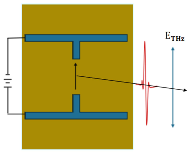
where n is the total charge carrier concentration, “ν” is the carrier drift velocity, A is the area of the antenna’s radiation surface, equivalent to the inter-electrode gap area, and c is the speed of light in vacuum. As evident from the formula, an increase in the applied bias electric field enhances the charge carrier drift velocity, thereby boosting the output power of the THz radiation. The THz radiation polarization remains parallel to the photocurrent flow direction. This is illustrated in
Figure 1, where the THz wave emitted by the dipole-type photoconductive antenna is linearly polarized, with its polarization angle parallel to the photocurrent flow direction. By offsetting the electrode structure, the direction of the photocurrent flow can be controlled, thereby enabling manipulation of the linear polarization angle of the emitted THz radiation. When the antenna structure is fabricated with a specific angular offset, the photocurrent flow direction exhibits a corresponding angular shift. This demonstrates that electrode offset enables active control of the photocurrent flow vector, thereby manipulating the polarization angles.
We developed a four semicircular electrodes photoconductive antenna with asymmetric electrode offsets that reconfigure carrier dynamics, constraining photocurrent vectors to angles in increments of 30°. Retaining the fundamental operating principle of conventional four-electrode photoconductive antennas, this design similarly radiates four linear polarization states by reconfigured bias voltage application across the four electrodes.
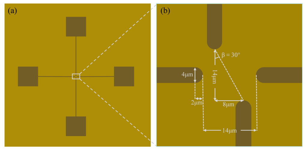
Figure 2 shows the schematic of asymmetric offset four-electrode photoconductive antenna.
Figure 2a is the overall structure: 10 × 10 mm low-temperature grown GaAs (LT-GaAs) substrate featuring two orthogonal semicircular dipole antennas, bias leads, and 1 × 1 mm bonding pads.
Figure 3b shows the magnified antenna active region: Electrodes (4 µm width) with 14 µm inter-electrode gaps. The horizontal dipole pair shows no offset (α = 0°), while the vertical pair exhibits bilateral 4 μm lateral offsets (β = 30°).
In conventional multi-electrode PCAs, the photocurrent direction is restricted by symmetric electrode pairs, yielding polarization angles at 45° increments. Our asymmetric offset semicircular design breaks the symmetry, allowing the photocurrent to flow along engineered paths that are not limited to these discrete directions. Meanwhile, the semicircular electrode shape reduces sharp corners, which cause electric field crowding and premature breakdown. This physical design choice enables a higher bias voltage to the increase of radiation power of 14.5 µW.
3. Results and Discussions
For multi-electrode photoconductive antennas, such as the commonly used four-electrode PCA, the structure can be decomposed into a pair of orthogonal dipole PCAs (horizontal and vertical sets). The offset angles and of the horizontal and vertical electrode have the following relations with the polarization angle of the terahertz radiation: (1) when the two dipoles are offset at the same angle (), and the polarization angles can be , , , , a total of four angles of linear polarization can be radiated, with a polarization angle interval Δθ of 45°; (2) when the dipole offset angles differ (), the resulting terahertz wave’s polarization angle θ is given by: , , , , the polarization angle interval Δθ is controlled by the electrode offset angles . By modulating the electrode offset angles α and β, the polarization angle θ and angle interval of terahertz radiation can be precisely controlled, thereby enhancing polarization angle diversity.
Using the Finite Element Method (FEM), we simulated the photocurrent generation in asymmetric offset four-electrode photoconductive antenna under laser excitation. The semiconductor material is LT-GaAs. Constrained by the Debye depth (approximately 0.8 µm), as well as by limitations in computer memory and computational efficiency, a uniform grid division is adopted with increments Δx = Δy = Δz = 0.8 µm. The time step Δt is set to 1.67 fs, satisfying the Courant stability condition and ensuring that the discretized finite-difference Maxwell’s equations produce a solution free from numerical dispersion. In the simulations, the carrier lifetime is 100 fs, and the full width at half maximum of the laser pulse is 100 fs. Metals are treated as perfect electric conductors (PEC). The high-refractive-index GaAs substrate has a dielectric constant of 12.9.
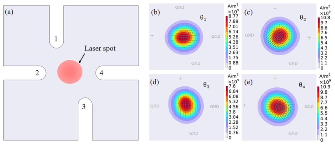
Figure 3 shows the resulting photocurrent flow directions, which switch when altering the bias voltage configuration across the antenna electrodes. In
Figure 3a, the four electrodes are, respectively, externally connected to bias voltages under femtosecond laser excitation. When electrode 2 is biased at a positive voltage with electrodes 1, 3, and 4 grounded, the photocurrent flows at an angle of
θ1 in the active area, as shown in
Figure 3b. When electrodes 1, 4 are biased at a positive voltage, with electrodes 2, 3 grounded, the photocurrent flows at an angle of
θ2 in the active area, as shown in
Figure 3c. When electrode 1 is biased a positive voltage with electrodes 2, 3, and 4 grounded, the photocurrent flows at an angle of
θ3 in the active area, as shown in
Figure 3d. When electrode 1, 2 is biased at a positive voltage with electrodes 3, and 4 grounded, the photocurrent flows at an angle of
θ4 in the active area, as shown in
Figure 3e.
Figure 3b–e demonstrate that the photocurrent density in each direction varies with the applied bias configuration. When positive voltage is simultaneously applied to two electrodes (
Figure 3c,e), the accelerating electric field in the active region exceeds that of single-electrode biasing (
Figure 3b,d). This enhanced field increases carrier drift velocity, resulting in proportionally higher photocurrent densities.
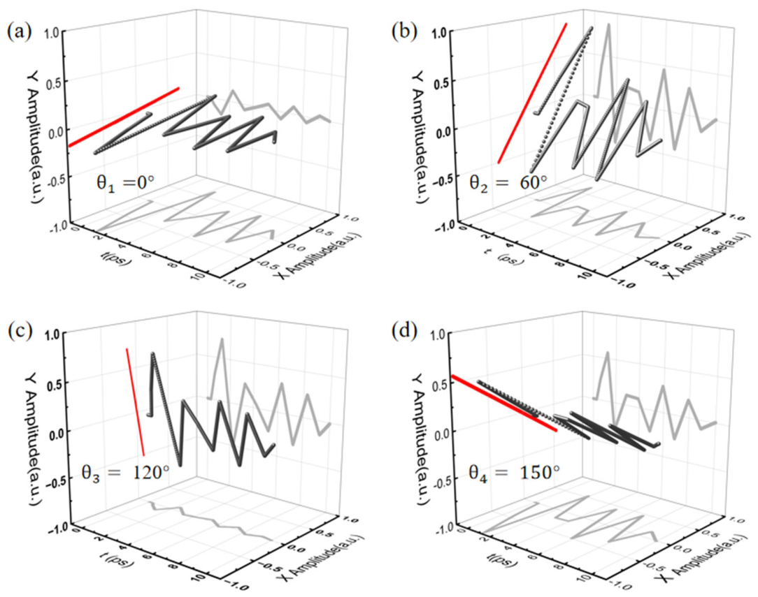
Asymmetric offset electrode and four bias configurations enable the radiation of linearly polarized terahertz waves with polarization angles in increments of 30°.
Figure 4 shows FEM-simulated time-domain electric field patterns of THz radiation from asymmetric offset four-electrode photoconductive antenna. Left-side projections visualize the polarization angles of emitted THz waves under four bias configurations. The THz polarization angle exhibits one-to-one correspondence with the photocurrent flow direction. However, due to nonuniform current distribution within the active region, a slight deviation exists between the radiated polarization angle and the photocurrent flow direction. Asymmetric offset four-electrode photoconductive antenna generates the four polarization states shown in
Figure 4 via bias voltage adjustment, thereby expanding the polarization diversity of terahertz waves radiated from photoconductive antennas. Furthermore, the minimal polarization distortion introduced by this design permits the elimination of polarizers in time-domain terahertz ellipsometry system. This significantly enhances system compactness and improves the SNR for polarization characterization in anisotropic materials.
The radiation power of polarization-tunable multi-electrode photoconductive antennas exhibits strong bias-voltage dependence. The maximum applicable bias voltage is constrained by the sharp geometry of the electrodes, fundamentally limiting the achievable THz radiation power. The breakdown of photoconductive antennas is governed by electrical breakdown and thermal breakdown. For direct-bandgap GaAs devices, electrical -breakdown is mainly caused by the sharp increased electric field due to the accumulation of space charges generated by the negative resistance effect at the anode [
31]. The breakdown voltage is primarily determined by electrostatic field distribution uniformity, material intrinsic properties, device structural dimensions, and thermal conditions. For GaAs, the breakdown field strength exhibits significant variations depending on doping concentration and growth temperature. LT-GaAs demonstrates superior intrinsic breakdown strength (>500 kV/cm), yet photoconductive antennas typically fail at much lower fields (~100 kV/cm). This is widely attributed to surface flashover or premature breakdown under applied bias, as supported by prior studies [
32,
33].
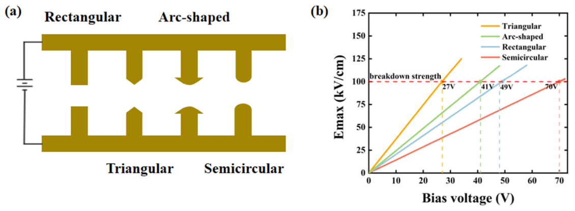
By optimizing the electrode shape of multi-electrode photoconductive antenna, the peak electric field intensity is significantly reduced, thereby enabling much higher applicable bias voltage. Using finite element method (FEM) simulations, we compare the required bias voltages and active-region field uniformity for semicircular, rectangular, triangular electrodes and arc-shaped electrodes PCA [
29] when maintaining a peak electric field of 100 kV/cm. As shown in
Figure 5, under the same applied bias voltage, the maximum electrostatic field varies with different electrode geometries. The sharper the electrode shape, the more negative resistance effect at the anode, resulting in a higher maximum electrostatic field. The simulation results illustrate the evolution of the maximum electrostatic field under increasing bias voltages for four distinct electrode geometries. Under the peak electrostatic field of 100 kV/cm, asymmetric offset four-electrode photoconductive antennas necessitate applied biases of 70 V, 49 V, and 27 V for the semicircular, rectangular, and triangular electrodes, respectively. Meanwhile, the symmetric arched electrode configuration requires a lower bias of 41 V.
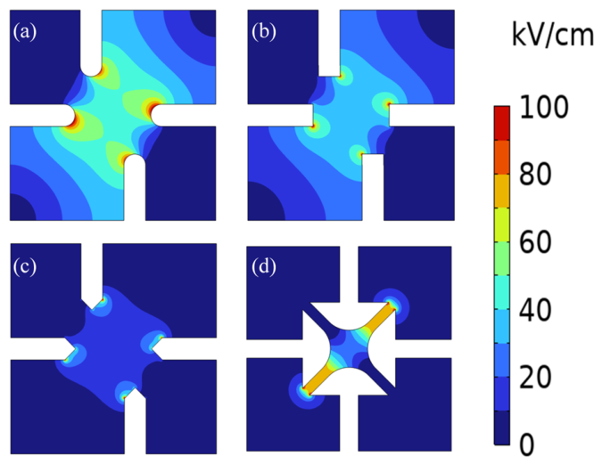
We implemented an optimized semi-circular electrode geometry, raising the applicable bias voltage of the multi-electrode photoconductive antenna to 70 V. The enhanced bias voltage increases the electrostatic field strength within the active region of the photoconductive antenna.
Figure 6 shows the electrostatic field distributions in LT-GaAs layer for four distinct electrode geometries. A comparison in
Figure 6 reveals that asymmetric offset four-electrode PCA with a semicircular electrode stands out by delivering a significantly greater average electric field intensity in its active region than the other three structures.
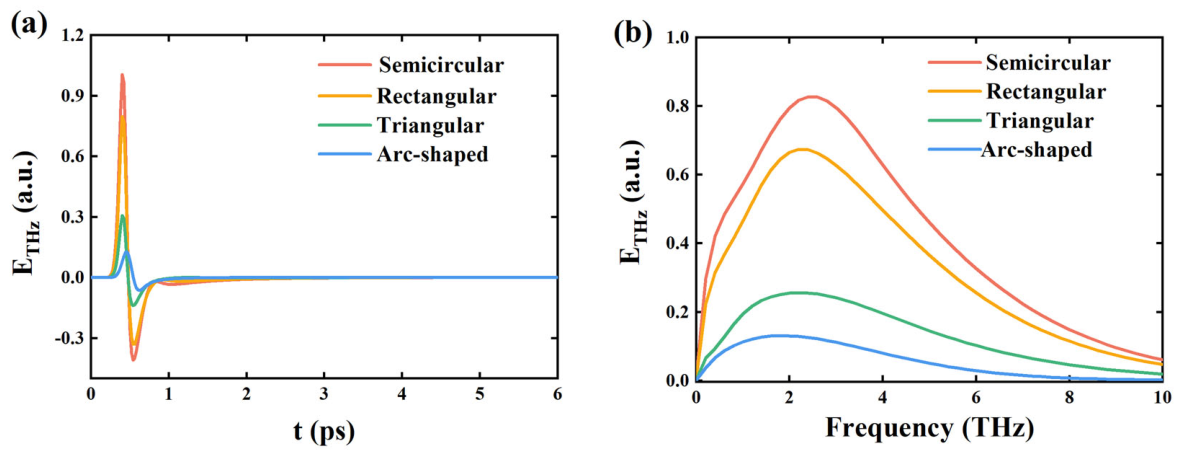
With increasing applied bias voltage, photogenerated carriers attain higher drift velocities under electric field acceleration, leading to enhanced peak photocurrent and consequently significant amplification of terahertz radiation field strength.
Figure 7 presents the terahertz radiation electric field (a) time domain and (b) frequency domain plots for the four structures under their respective maximum bias voltages. As the electric field in the active region intensifies, asymmetric offset semicircular multi-electrode photoconductive antenna exhibits a marked increase in its peak terahertz radiation field compared to the other three structures.
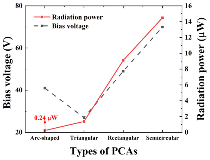
Figure 8 shows the simulated radiated power for the four structures at their respective maximum bias voltages. Asymmetric offset four-electrode photoconductive antenna with semicircular electrodes achieves a radiation power of 14.5 µW.
Asymmetric-offset semi-circular electrode design offers diversified polarization angles, increased radiation power, and low polarization distortion, while eliminating external polarizers. It is promising for enhancing system integration in time-domain terahertz ellipsometry system and improving the SNR for polarization characterization in anisotropic materials.
Table 1 summarizes the radiated polarization states, applied bias voltage, and the need for supplementary polarizers in existing polarization-tunable photoconductive antennas. Semi-circular asymmetric-offset four-electrode photoconductive antenna addresses two key shortcomings of prior approaches: it overcomes the limited polarization diversity of conventional multi-electrode antennas and eliminates the high distortion typical of interdigital arrays when generating multiple polarization states. Additionally, its semi-circular geometry enables a higher bias voltage, resulting in significantly enhanced terahertz radiation power.