1. Introduction
In fields such as aerospace [
1], aviation [
2], polar exploration [
3], and cryogenic storage [
4], equipment is routinely subjected to extreme environmental conditions, including large temperature gradients and strong electromagnetic interference. These harsh environments impose stringent requirements on sensing systems in terms of environmental adaptability, anti-interference capability, and measurement accuracy. Among various parameters, real-time and reliable temperature monitoring is critical for ensuring system safety and operational stability.
Conventional electrical temperature sensors exhibit significant limitations under such conditions [
5]. Their relatively large size restricts their use in confined spaces, while their susceptibility to electromagnetic interference and strict environmental requirements further limit their applicability. In low-temperature environments, these sensors often suffer from slow response times, reduced sensitivity, and even performance degradation or failure, which severely compromises measurement accuracy and system reliability.
Fiber Bragg grating (FBG) sensors have emerged as a promising alternative due to their inherent advantages, including immunity to electromagnetic interference, fast response, compact size, and cost-effectiveness [
6]. These features make them well suited for temperature monitoring in harsh environments. However, bare FBG sensors fabricated from quartz exhibit intrinsic limitations, such as a low thermal expansion coefficient and limited shear resistance. As a result, their temperature sensitivity is relatively low [
7], particularly in low-temperature conditions, which hinders accurate temperature measurement. Therefore, enhancing the temperature sensitivity of FBG sensors through appropriate structural design and packaging strategies is of significant practical importance.
To address this issue, several sensitization methods have been proposed, including surface metallization [
8], metal-structured encapsulation [
9], and polymer-based packaging [
10]. Surface metallization enhances sensitivity by depositing metal coatings on the FBG using techniques such as magnetron sputtering, electroless plating [
11], or vacuum evaporation. For example, Mishra et al. achieved a sensitivity of 50.8 pm/K using indium-coated FBG sensors in the temperature range of 50–300 K [
12], while Wang et al. reported a sensitivity of 28.3 pm/K for Ti–Cu coated FBGs over 79–298 K [
13]. However, these methods typically involve complex fabrication processes and are not suitable for low-cost, large-scale production.
Metal encapsulation improves temperature sensitivity and mechanical robustness by embedding the FBG within a metal structure. Li et al. reported a sensitivity of 27.3 pm/°C using an aluminum alloy package [
14], and Cai et al. achieved 50.2 pm/°C with a hybrid aluminum–invar structure [
15]. Nevertheless, metal packaging suffers from high cost, increased weight, and limited flexibility, which restrict its applicability in weight- and cost-sensitive scenarios.
Polymer encapsulation, which utilizes materials with high thermal expansion coefficients, has attracted considerable attention due to its simplicity, low cost, and enhanced sensitivity. Additionally, polymer materials provide good flexibility and chemical stability, offering effective protection against mechanical damage and corrosion. Sengupta et al. reported a sensitivity of 39 pm/°C using polymethyl methacrylate coatings over −196 to 30 °C [
16], while Sampath et al. achieved 48 pm/°C in the range of −180 to 25 °C [
17]. Cai et al. further reported a maximum sensitivity of 69.4 pm/°C using epoxy coatings [
18]. However, polymer-based approaches may suffer from stability issues, leading to increased measurement uncertainty.
To overcome these limitations, this study employs polytetrafluoroethylene (PTFE) as a sensitization material. PTFE offers excellent chemical stability, electrical insulation, and a relatively high thermal expansion coefficient, along with good thermal conductivity. Furthermore, its tubular encapsulation structure provides effective mechanical protection for the FBG.
Based on these advantages, a PTFE-based encapsulation scheme combined with different adhesives is proposed to enhance the temperature sensitivity of FBG sensors. Thermal stress distributions under different adhesive conditions are analyzed using COMSOL simulations. In addition, the effects of structural parameters, including PTFE length and thickness, are experimentally investigated. The proposed sensor is validated through temperature calibration and thermal cycling tests, demonstrating improved sensitivity, stability, and practical applicability for low-temperature environments.
2. Fabrication and Principle of the Sensor
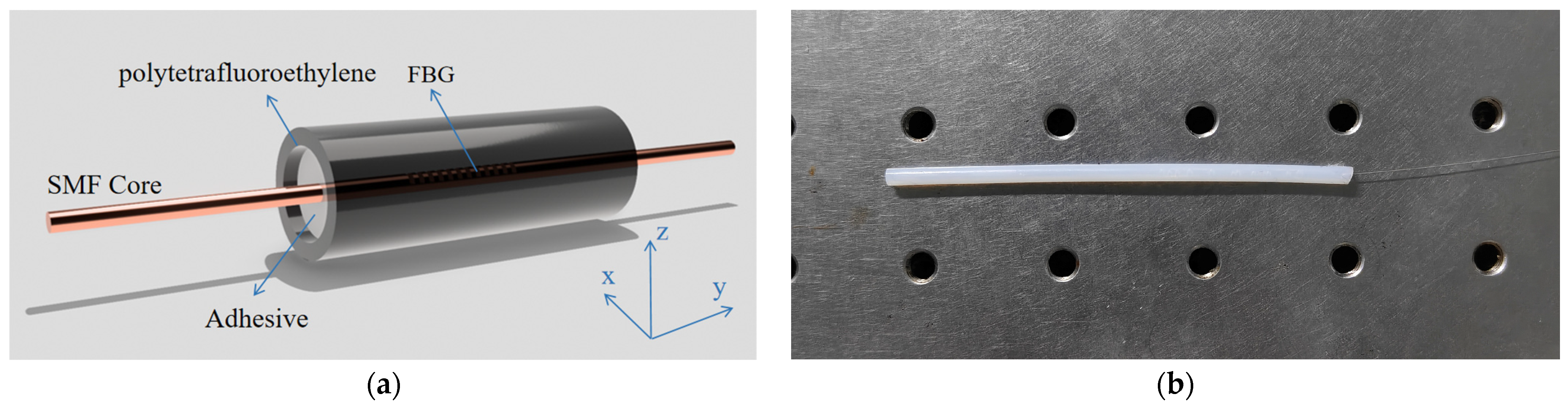
The FBG temperature sensor encapsulated in PTFE has an initial center wavelength of 1550 nm and a grating length of 10 mm. A PTFE tube with an outer diameter of 3 mm, inner diameter of 1 mm, wall thickness of 1 mm, and length of 8 cm was selected. A schematic diagram of the PTFE-encapsulated FBG temperature sensor is shown in
Figure 1a, where the outermost layer is PTFE and the optical fiber is encapsulated within the PTFE tube using an adhesive.
Figure 1b shows a photograph of the fabricated sensor.
To systematically compare the effects of different adhesive types on the performance of FBG temperature sensors, four distinct adhesive materials were employed for encapsulating the FBGs.
Metallographic rapid-curing cold-mount epoxy resin was first selected as the encapsulation material. Epoxy resin is one of the most widely used materials for sensor packaging and structural bonding because of its high bonding strength, low curing shrinkage, excellent chemical stability, and low cost. The epoxy resin and hardener were mixed at a weight ratio of 2:1 and stirred thoroughly in a single direction for 2–3 min until no string-like filaments were observed. The mixture was then allowed to stand until all bubbles had disappeared. The FBG was threaded through the PTFE tube and fixed under a predetermined preload, with the grating positioned at the center of the tube. Bubble-free epoxy resin was then injected into the gap between the PTFE tube and the FBG using a syringe. The encapsulated sensor was cured at room temperature for 24 h before testing.
Modified acrylic ester was selected as the second encapsulation adhesive. This material retains the rapid curing and ease of processing characteristic of acrylic adhesives, while exhibiting improved toughness and temperature resistance after modification. Owing to its balanced bonding performance and fast curing behavior, it is widely used as an elastic bonding material in encapsulation applications. Components A and B were mixed at a 1:1 ratio in a glass container and stirred clockwise for 1 min. Care was taken to avoid entrapping air during mixing. After the mixture reached a uniform viscous state, vacuum degassing was performed. The adhesive was then rapidly injected into the PTFE tube containing the preloaded FBG, while ensuring that the FBG remained centered within the tube.
Polydimethylsiloxane (PDMS) was selected as the third encapsulation material. PDMS has an extremely low elastic modulus, excellent flexibility, and a relatively high coefficient of linear thermal expansion. These properties provide effective stress buffering and protection for temperature sensors, making PDMS a representative material for flexible encapsulation. The PDMS base and curing agent were mixed at a mass ratio of 10:1 and stirred thoroughly in one direction. After complete mixing, the solution was vacuum-degassed and then injected into the PTFE tube using an adhesive injector. The encapsulated sensors were subsequently pre-cured at 60 °C for 1 h and post-cured at 100 °C for 30 min.
The fourth encapsulation material was an organic silicone thermal sealant (OSTS). This adhesive exhibit high elasticity, good resistance to both high and low temperatures, and excellent thermal conductivity, enabling reliable bonding and effective thermal transfer. It is therefore suitable for device encapsulation in applications requiring temperature uniformity. The adhesive was directly dispensed into the gap between the FBG and the PTFE tube. After curing at room temperature for 36 h, the sensor was subjected to testing.
According to the coupled-mode theory of FBG, when incident broadband light satisfies the Bragg condition, the periodic structure of the refractive index renders the fiber core internally equivalent to a narrow-band filter. This causes light of specific wavelengths to be reflected while other wavelengths are transmitted. The center wavelength of the reflected light from an FBG satisfies the Bragg condition:
In the equation,
denotes the center wavelength of the reflected light from the FBG,
represents the effective refractive index of the fibre core, and
signifies the period of the FBG. Equation (1) shows that the central wavelength of the FBG reflection is determined by
and
. The effective refractive index varies due to thermo-optic and elastoptic effects, while the period changes with temperature or external loading, consequently altering
[
19]. Correspondingly, the change in the reflected wavelength of the FBG reflects alterations in the measured quantity, with the wavelength shift being expressed as a linear superposition of the thermo-optic effect, the elastically optic effect, and periodic variations.
In Equation (2), denotes the change in the centre wavelength of the FBG, represents the thermal expansion coefficient of the optical fibre, signifies the thermo-optic coefficient, denotes the elastic-optic coefficient of the fibre, indicates the change in temperature, and represents the change in stress within the grating.
Let
,
. To eliminate the influence of external stresses and ensure that the FBG sensor responds solely to temperature, the initial strain is assumed to be zero. Accordingly, the shift in the Bragg wavelength can be expressed as:
After sensitivity enhancement through encapsulation with a material possessing a relatively large coefficient of thermal expansion, the additional strain induced by the polymer coating under temperature variation further amplifies the wavelength shift in the FBG. The thermal stress generated at the fiber–polymer interface enforces strain compatibility between the two materials, thereby significantly improving the sensing performance. The induced common strain can be expressed as:
where
represents the thermal expansion coefficient of the polymer,
and
denote the strain variations in the optical fiber and the polymer relative to their initial strains. During temperature changes, the expansion of the polymer exerts thermal stress
on the optical fiber, while the polymer itself is subjected to thermal stress
applied by the optical fiber. Their equilibrium equations are as follows:
and
are the elastic moduli of optical fiber and polymer respectively, while
and
represent their cross-sectional areas. Their strain variations are expressed as follows:
The relationship between the central wavelength variation in FBG after sensitization packaging and temperature change is as follows:
By rearranging the above expression, the temperature sensitivity of the encapsulated FBG sensor is obtained as:
From the above equation, it can be observed that when the ambient temperature changes, the encapsulation material of the FBG sensor undergoes stress due to expansion or contraction. This induces corresponding alterations in the material’s microstructure, leading to changes in the FBG period and refractive index. Consequently, this enhances the temperature sensitivity of the FBG sensor.
3. Results and Discussion
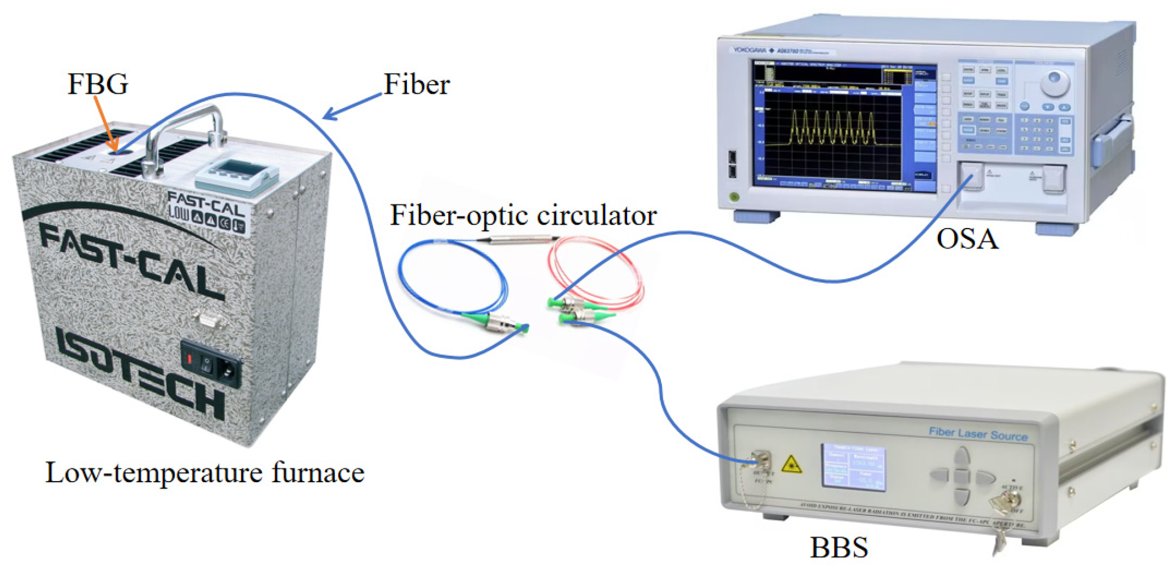
The experimental setup for PTFE-encapsulated FBG temperature sensor characteristics is shown in
Figure 2. Temperature experiments were conducted using the FC140S-WF low-temperature calibration furnace (developed by ISOTECH UK), with a temperature control range of −35 °C to 140 °C and an accuracy of 0.01 °C. The experimental data monitoring instruments consist of a spectrum analyzer (OSA) (YOKOGAWA-AQ6370C) and a broadband light source (BBS). The low-temperature sensing system records the center wavelength shift in the FBG during the heating process using the spectrum analyzer.
This experiment employed a bare FBG with a center wavelength of 1543 nm alongside four encapsulated FBG temperature sensors for comparison, with the aim of verifying the sensitization effect of PTFE combined with different adhesives under low-temperature conditions. Both the encapsulated FBG sensors under test and the bare FBG were simultaneously placed in a low-temperature calibration chamber. Set the temperature range to −35 °C to 15 °C with 5 °C intervals, and conduct two heating experiments. Whenever the temperature rises to the set point, maintain it for 15 to 20 min. After confirming the temperature change is accurate, record the center wavelength of the FBG at the corresponding temperature point on the spectrometer.
3.1. Experimental Analysis of Sensing Characteristics
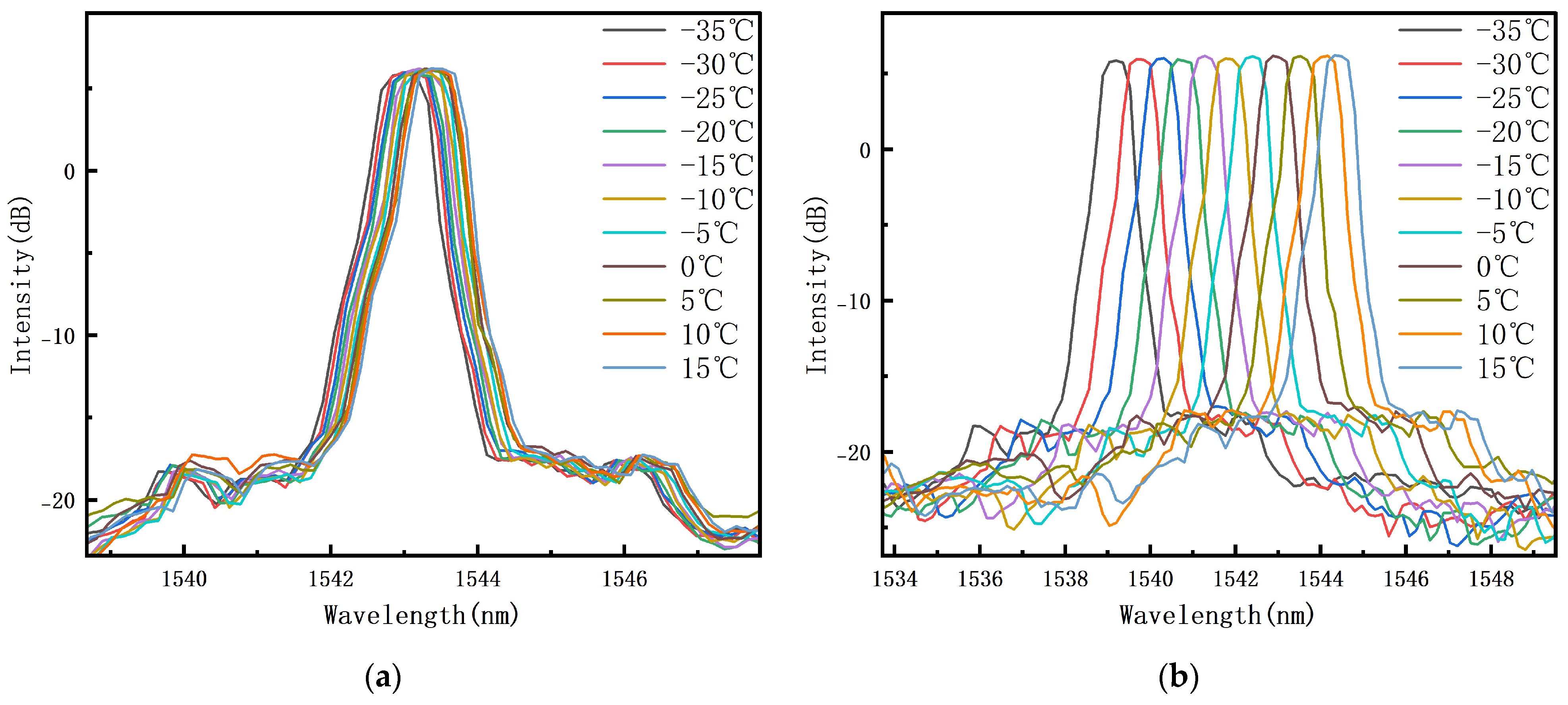
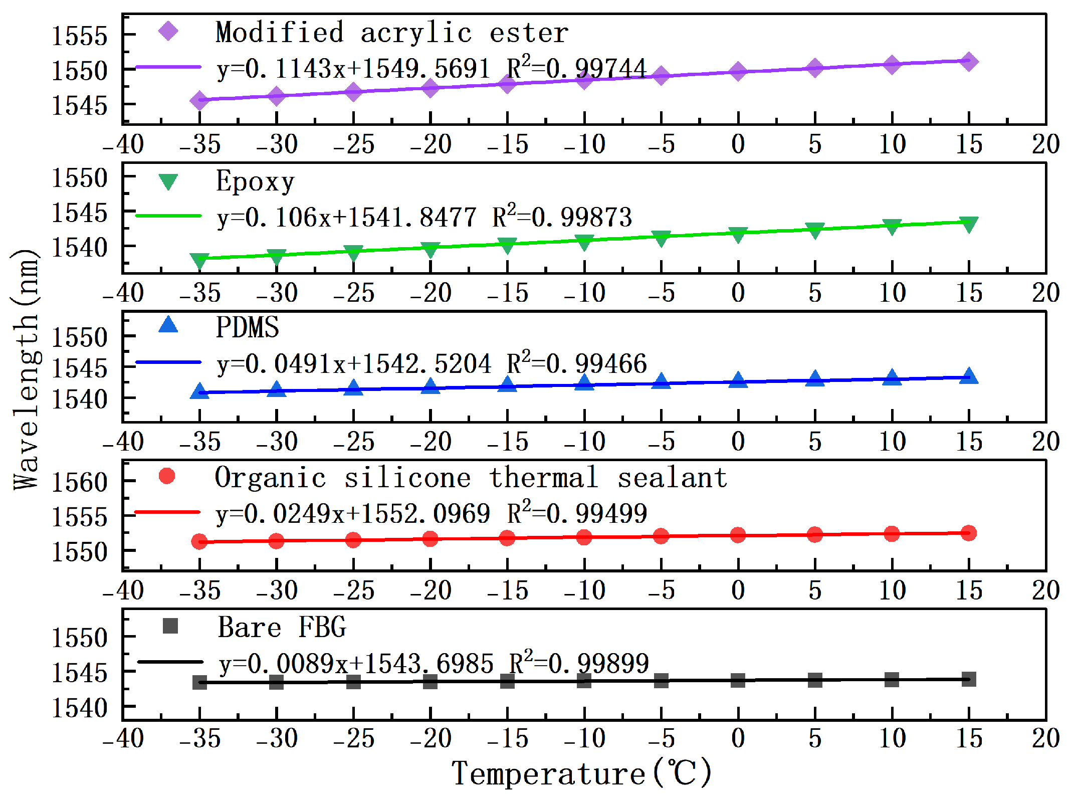
Within the tested temperature range of −35 °C to 15 °C, the drift of the center wavelength of PTFE-encapsulated FBG temperature sensors and bare FBG with respect to temperature variation, using epoxy resin as the adhesive, is shown in
Figure 3.
The encapsulated reflectance spectrum exhibits a favorable shape with no significant distortion, indicating that minimal non-uniform axial stress was generated along the FBG direction during the encapsulation process. It can be observed that the drift in the center wavelength of the encapsulated FBG temperature sensor with respect to temperature is significantly greater than that of the bare FBG center wavelength. After processing and analyzing the drift values of the FBG temperature sensors encapsulated with the other three adhesives, their temperature sensitivities were obtained, as shown in
Figure 4.
As shown in
Figure 4, after sensitization encapsulation, the bare FBG exhibits a temperature sensitivity of 8.9 pm/°C. The temperature sensitivity of the OSTS temperature sensor in a PTFE package reaches 24.95 pm/°C. The PDMS-encapsulated sensor exhibits a temperature sensitivity of 49.1 pm/°C, while the epoxy resin-encapsulated sensor reaches 106 pm/°C. Modified acrylic resin encapsulation yields 114.3 pm/°C for the PTFE-encapsulated sensor. Compared to the bare FBG, encapsulation enhances temperature sensitivity by up to approximately 12.85 times. The temperature sensitization effect is prominent.
Let the experimental value be
and the fitted value be
; the maximum deviation
can be calculated as follows:
The full-scale output is:
Let
be the total wavelength drift,
the maximum wavelength, and
the minimum wavelength. The linear error is:
From the above equation, the linear errors of the five fitted curves can be calculated, with a maximum value of 3.36%. Although there is some nonlinearity in certain temperature zones, the sensor maintains good overall linear response.
According to Formula (8), the theoretical temperature sensitivity value for the PTFE-encapsulated temperature sensor is obtained as 102.41 pm/°C. However, there exists a partial discrepancy between the theoretical and experimental values. Analysis of the data and review of the experimental procedures reveal that the primary causes of the discrepancies stem from the following circumstances:
The FBG temperature sensitivity formula retains only the first-order temperature and first-order strain terms, neglecting the higher-order terms of the thermo-mechanical coupling.
Polymers may contain internal defects, such as microbubbles and uneven curing, and during the actual fabrication of sensors, issues such as eccentricity and dimensional deviations may arise, resulting in discrepancies from the ideal geometric dimensions and standard thicknesses specified in the formula.
3.2. Simulation Analysis
Under the same packaging structure, the use of different adhesives resulted in varying levels of temperature sensitivity. To more intuitively evaluate the influence of adhesive properties on the sensitivity enhancement of FBG temperature sensors, a numerical model was established using COMSOL Multiphysics.
Free mechanical boundary conditions were applied to eliminate the influence of external constraint-induced stresses on the simulation results. To simulate heat input and transfer processes, convective heat flux boundary conditions were imposed on the model surface, expressed as:
where
is the unit normal vector to the boundary,
is the heat flux,
is the convective heat transfer coefficient,
is the external temperature, and
is the boundary temperature.
Additionally, surface-to-ambient radiation boundary conditions were incorporated to account for multimode heat transfer effects and to improve the accuracy of thermal stress simulations under low-temperature conditions. This relationship is given by:
where
is the surface emissivity,
is the Stefan–Boltzmann constant, and
is the ambient temperature.
Table 1 shows the specific material parameters used in the simulation.
In the table, represents the coefficient of thermal expansion, represents the modulus of elasticity, represents Poisson’s ratio, represents density, represents specific heat capacity, and represents thermal conductivity.
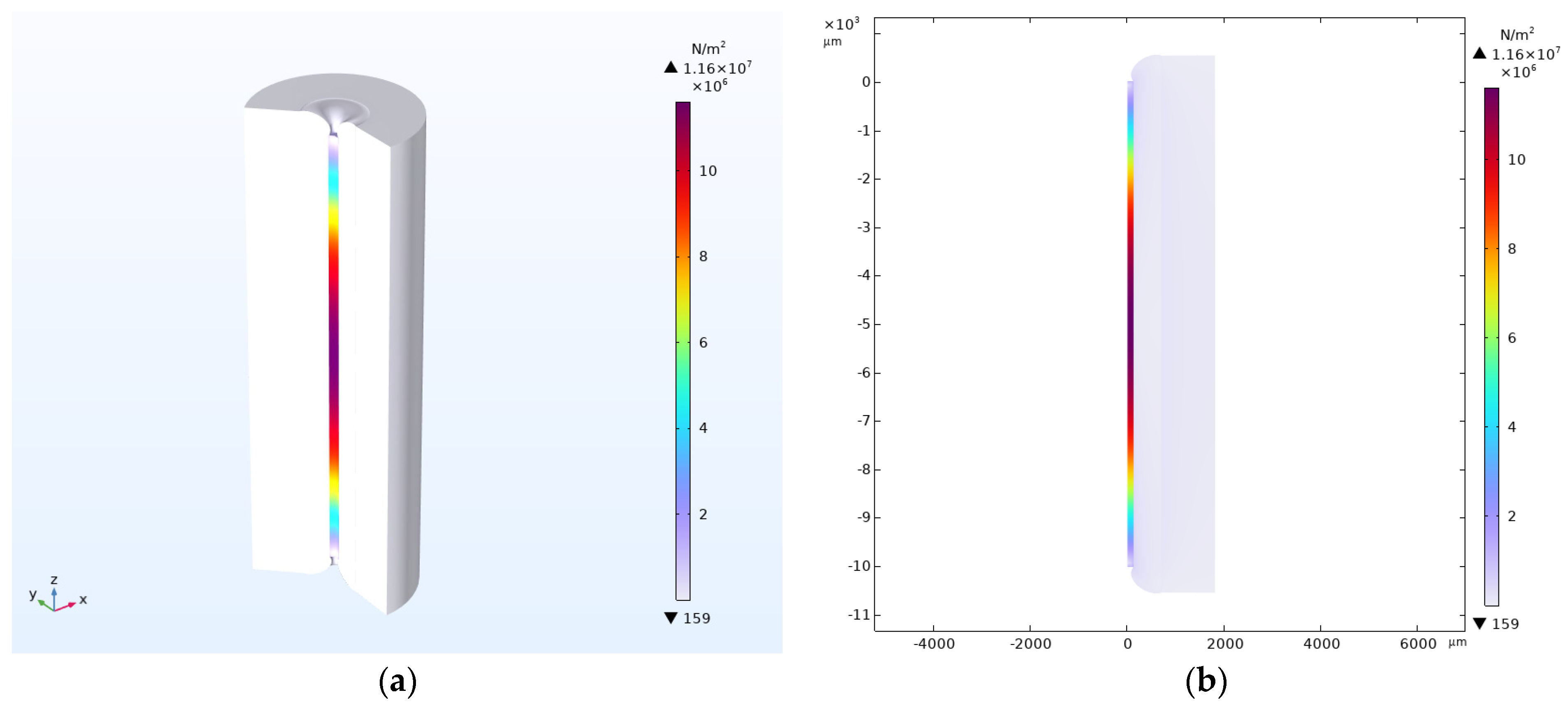
Figure 5 illustrates a simulated structure where the FBG is encapsulated within a PTFE tube with an outer diameter of 3 mm and an inner diameter of 1 mm, using PDMS as the adhesive with a thickness of 0.5 mm. Through numerical simulation, the stress distribution patterns and magnitudes induced in the FBG by the thermal expansion effects of the PTFE tube wall and PDMS adhesive within the temperature range of −35 °C to 15 °C were analyzed.
The results indicated that the stress experienced by the FBG was 1.16 × 10⁷ N/m2. Upon replacing the adhesive layer with epoxy resin, the results showed that the stress experienced by the FBG was 9.72 × 10⁷ N/m2, representing an approximately 8.3-fold increase in stress magnitude. Simulation results indicate that the organic silicone thermal sealant exhibits the lowest stress value at merely 5.89 × 10⁶ N/m2, whilst the modified acrylic ester demonstrates the highest simulated value at 1.62 × 10⁸ N/m2. Changes in thermal stress cause corresponding variations in the wavelength drift of the FBG, resulting in significant differences in temperature sensitivity among PTFE sensors encapsulated with the four adhesives.
3.3. Low-Temperature Testing of PTFE-Encapsulated Sensors at Different Thicknesses
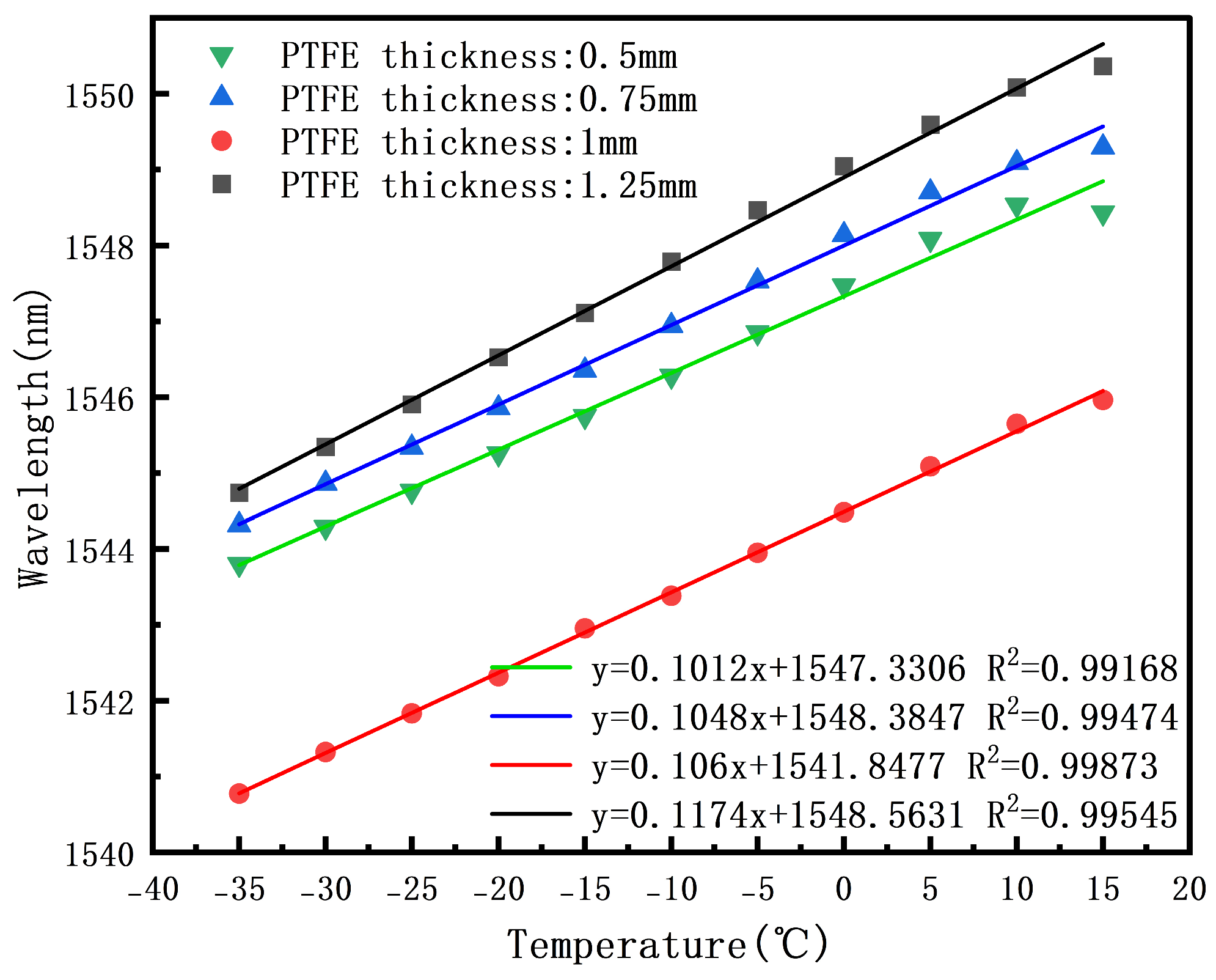
Four PTFE tubes with the same outer diameter of 3 mm and inner diameters of 0.5, 1.0, 1.5, and 2.0 mm, respectively, were selected. Each tube had a length of 8 cm. The FBGs were encapsulated according to the preparation procedure described above to investigate the effect of PTFE wall thickness on the temperature-sensitization performance of the sensor structure.
Each of the four encapsulated PTFE temperature sensor groups was tested individually, and two thermal cycles were performed for each group. The resulting data were linearly fitted, as shown in
Figure 6.
As shown in
Figure 6, the temperature sensitivity increased with increasing PTFE wall thickness. Specifically, the sensitivity was 101.2 pm/°C at a wall thickness of 0.5 mm, 104.8 pm/°C at 0.75 mm, 106.0 pm/°C at 1.0 mm, and 117.4 pm/°C at 1.25 mm. These results indicate that increasing the PTFE wall thickness can effectively enhance the temperature sensitivity of the encapsulated FBG sensor.
A notable phenomenon can also be observed in
Figure 6: for all four groups with different PTFE wall thicknesses, the drift of the center wavelength decreases within the temperature range of 10 °C to 15 °C. When the temperature gradually rises, the helical oscillations and thermal vibrations of the molecular chains within the PTFE triclinic crystal structure continue to increase, weakening the intermolecular bonding; When the temperature approaches 19 °C, the energy generated by molecular thermal motion is sufficient to overcome intermolecular forces and the torsional energy barrier of the chain segments, causing the molecular chains to gradually rearrange into a face-centered cubic packing structure and form a long-range ordered hexagonal crystal system. This makes 19 °C the first critical point for a sudden change in the physical properties of PTFE.
Within the temperature range of 10 to 15 °C, even though the characteristic phase transition temperature of 19 °C has not yet been reached, the material has already exhibited localized lattice relaxation and partial phase transitions. The slight decrease in elastic modulus causes a redistribution of interfacial stress between the PTFE and the adhesive, reducing the efficiency of stress transfer to the FBG and decreasing the effective strain input, which in turn reduces the wavelength shift in the FBG.
3.4. Low-Temperature Testing of PTFE-Encapsulated Sensors at Different Lengths
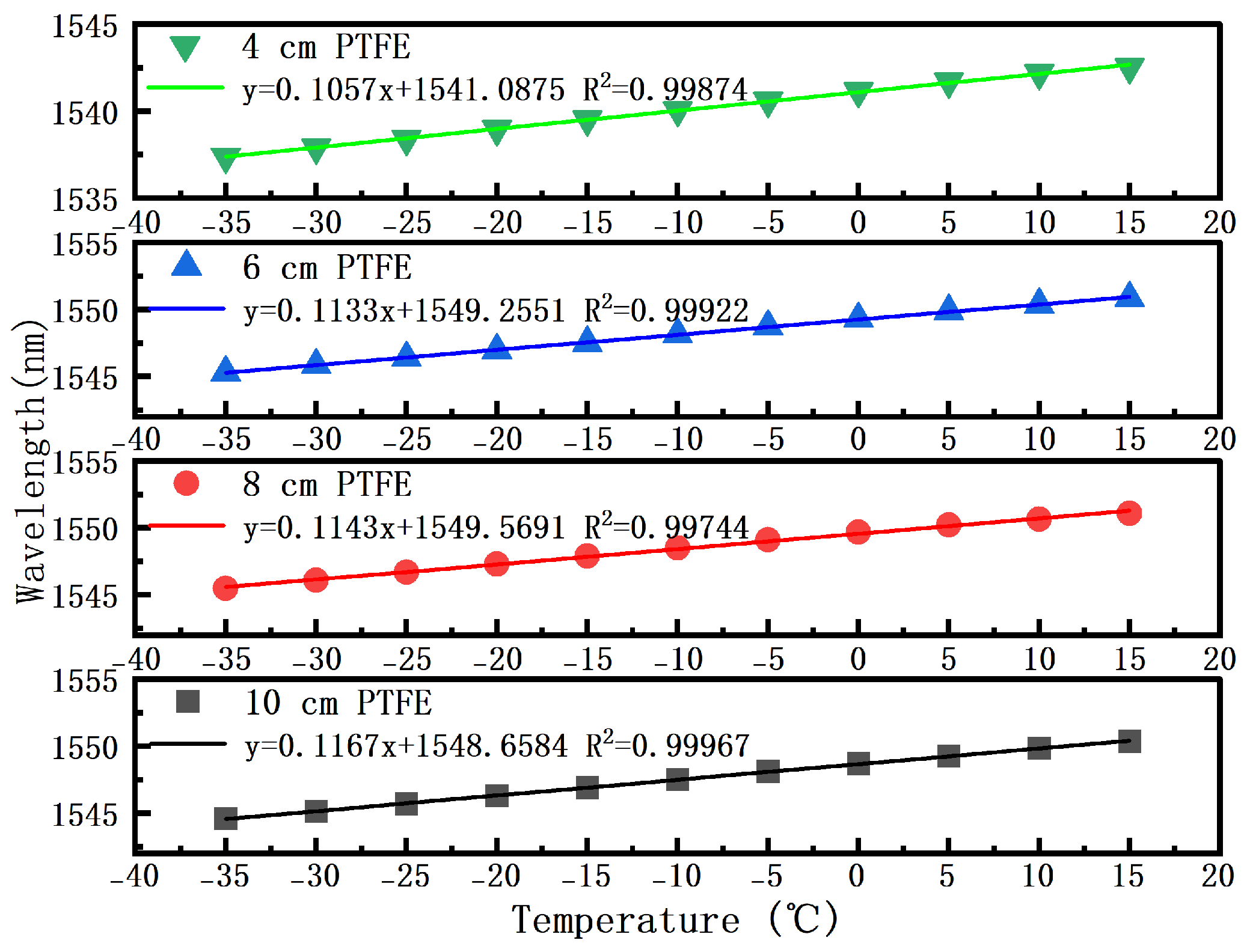
To further investigate the effect of PTFE tube length on the temperature sensitivity of the encapsulated FBG sensor, four PTFE tubes were selected with the same outer diameter of 3 mm and inner diameter of 1 mm, but with lengths of 4, 6, 8, and 10 cm, respectively. These tubes were encapsulated following the same preparation procedure to fabricate FBG temperature sensors with different encapsulation lengths.
Each of the four sensor groups was tested individually, and two thermal cycles were performed for each group. The experimental data were then linearly fitted, as shown in
Figure 7.
The results in
Figure 7 show that the temperature sensitivity decreases as the PTFE tube length decreases. The measured sensitivities were 116.7 pm/°C at a length of 10 cm, 114.3 pm/°C at 8 cm, 113.3 pm/°C at 6 cm, and 105.7 pm/°C at 4 cm. These results demonstrate that increasing the encapsulation length is beneficial for enhancing the temperature sensitivity of the sensor.
This trend suggests that a longer PTFE encapsulation length improves the mechanical coordination and strain transfer between the FBG and the PTFE tube. As a result, the Bragg wavelength shift is increased, leading to improved temperature sensitivity. Therefore, when this encapsulation structure is adopted, the sensor length should be appropriately increased to further enhance its temperature-sensing performance.
3.5. Repeatability and Long-Term Stability Tests
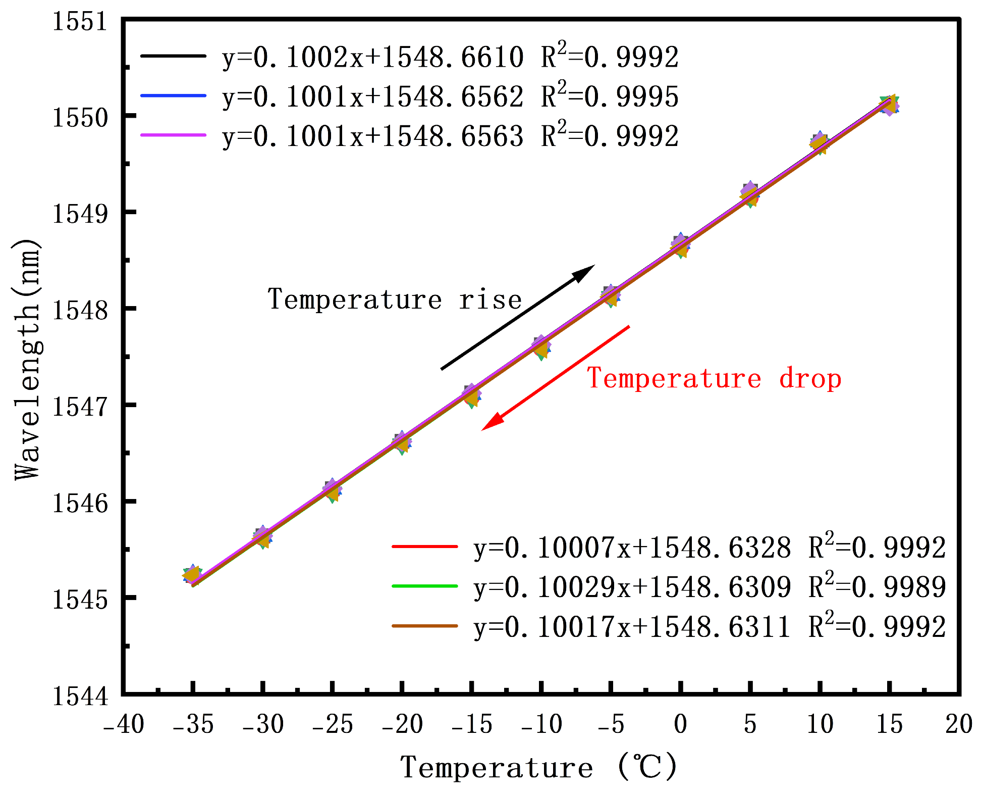
To characterize the repeatability of the PTFE-encapsulated FBG temperature sensor under varying temperatures, three independent and complete temperature cycling tests were conducted on the sensor. The center wavelength data of the FBG reflection spectrum were recorded throughout the entire experiment, as shown in
Figure 8.
The wavelength changes curves for the three cycles show a high degree of overlap, and the slopes of the fitted curves are nearly identical, indicating that the output characteristics of this encapsulated FBG sensor remain stable after multiple independent temperature cycles, demonstrating excellent temperature measurement repeatability.
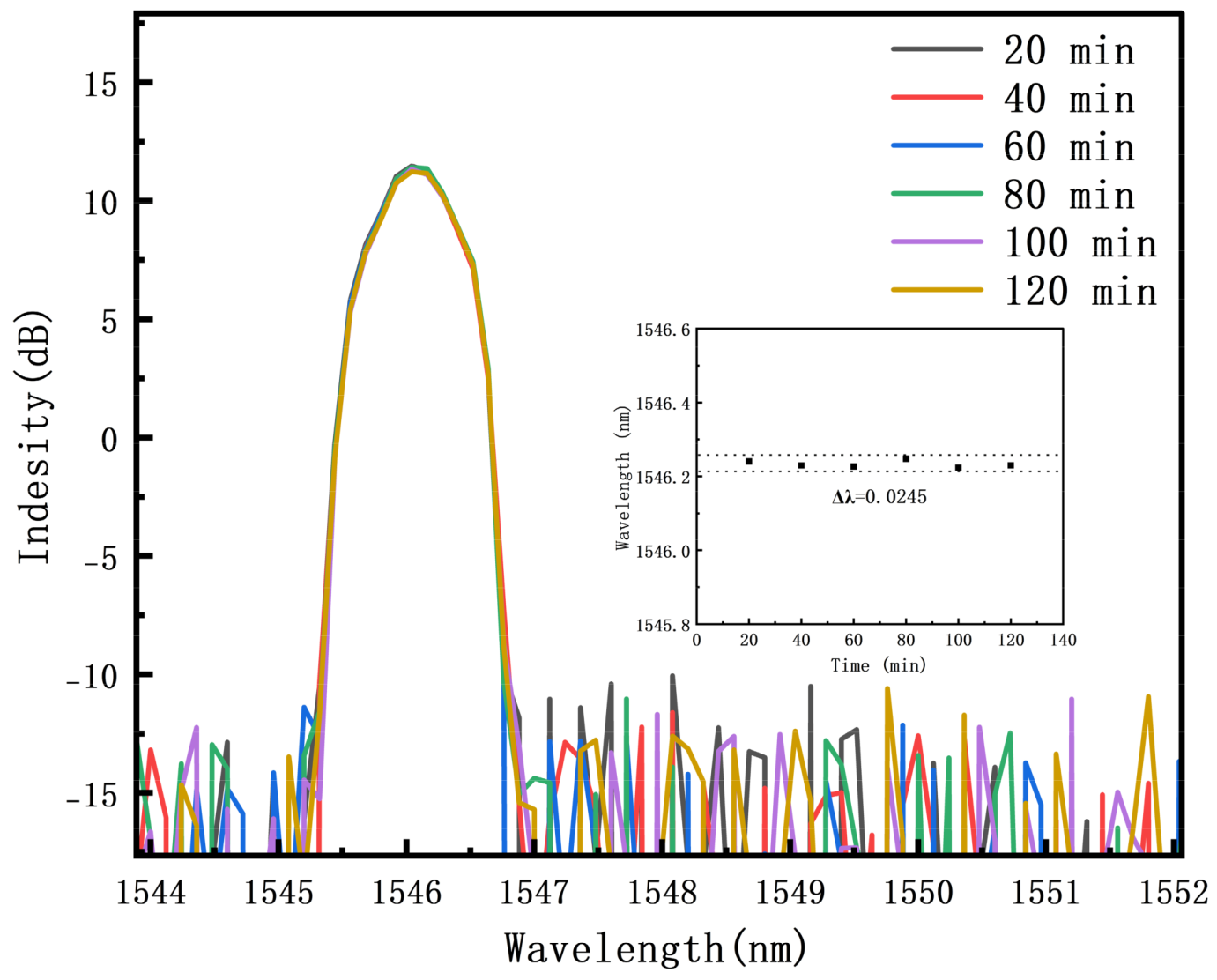
Long-term stability tests were conducted on the FBG temperature sensor, as shown in
Figure 9.
As shown in
Figure 9, under identical temperature conditions, the spectrum did not undergo any significant changes over a two-hour period, and the peak wavelength fluctuated only minimally, indicating that this encapsulated fiber Bragg grating sensor exhibits excellent long-term stability.



 ,
,