Article

Design and Fabrication of Volume Phase Holographic Gratings for CO2 Detection: A Multi-Objective Optimization Approach

1
Changchun Institute of Optics, Fine Mechanics and Physics, Chinese Academy of Sciences, Changchun 130033, China
2
University of Chinese Academy of Sciences, Beijing 100049, China
3
State Key Laboratory of Advanced Manufacturing for Optical Systems, Changchun 130033, China
*
Authors to whom correspondence should be addressed.
Photonics 2026, 13(5), 501; https://doi.org/10.3390/photonics13050501
Submission received: 10 March 2026 / Revised: 29 April 2026 / Accepted: 1 May 2026 / Published: 18 May 2026
(This article belongs to the Section Lasers, Light Sources and Sensors)

Abstract

Volume phase holographic gratings (VPHGs) are high-performance dispersive elements characterized by high diffraction efficiency and low noise. When used as dispersive components in imaging spectrometers for CO2 detection, they can significantly enhance instrument performance, detection capability, and measurement accuracy. However, for short-wave infrared (SWIR) applications requiring high dispersion and operational efficiency, traditional design approaches struggle to effectively balance the trade-offs among multidimensional diffraction performance metrics, resulting in low optimization efficiency. Furthermore, as spectrometers require dispersive elements, established fabrication methods lack robust methodologies for producing large-area VPHGs. To address these gaps, we developed both a design approach and a fabrication process for VPH gratings tailored to CO2 detection. On the design front, we propose a novel method that integrates a multi-objective simulated annealing optimization algorithm with Kogelnik’s coupled-wave theory. The optimized gratings achieve diffraction efficiencies of 95.35% (TE polarization) and 82.21% (TM polarization) across the target spectral range, with polarization sensitivity maintained below 6.57%. For fabrication, we developed holographic plate fabrication via a blade-coating technique coupled with an optimized aging protocol. A medium-to-large aperture holographic recording and exposure system with a wavefront error better than λ/25 RMS was developed. Post-processing conditions were systematically optimized based on experimental diffraction efficiency measurements, enabling the successful fabrication of VPHGs. It is explicitly noted that the experimental validation of the fabricated VPHGs is limited to the 1.620–1.630 μm wavelength range, while the full target design range of 1.620–1.650 μm has not been experimentally verified in this work. This work provides a valuable reference for the selection of dispersive elements for next-generation CO2 detection satellites. The designed gratings fully meet application requirements, while the established fabrication process lays a solid foundation for the production of high-performance VPHGs.

1. Introduction

In recent years, the escalating greenhouse effect has severely impacted natural ecosystems and human activities. The primary contributor to this phenomenon is carbon dioxide (CO2), the most prevalent greenhouse gas [1,2]. By 2024, atmospheric CO2 concentrations had exceeded 420 ppm, increasing at a rate of 2–3 ppm annually—more than a 50% rise and the highest level in the past 800,000 years. According to the Intergovernmental Panel on Climate Change (IPCC), without substantial reductions in CO2 emissions, global temperatures are projected to rise by more than 2 °C, potentially causing irreversible environmental damage. Therefore, accurate monitoring of CO2 concentrations is of critical importance for climate change mitigation strategies. In response to the serious risks posed by rising CO2 levels, nations including the United States, China, Japan, and European Union member states have developed satellite-based CO2 monitoring technologies. Several satellites equipped with CO2 detection capabilities have been launched, including ENVISAT, CarbonSat [3], Sentinel-5P [4], TanSat, FY-3D, GF-5 [5], GOSAT [6], and the OCO series [7,8]. These satellites utilize imaging spectrometers to measure infrared absorption spectra, enabling the retrieval of atmospheric gas concentrations. Most systems employ diffraction grating-based spectrometers to acquire spectral data—a well-established and widely adopted approach [9]. As the core dispersive component, the diffraction grating plays a critical role in determining overall instrument performance and detection sensitivity. Consequently, the development of high-performance diffraction gratings has become a key priority for next-generation CO2 observation satellites. VPHGs are three-dimensional diffractive optical elements fabricated using holographic techniques within a photosensitive medium. Their grating structures are embedded throughout the entire volume of the material. VPHGs exhibit distinctive physical properties, including high diffraction efficiency, excellent wavelength and angular selectivity, and low polarization sensitivity [10,11]. They also offer low noise, high resolution, and uniform dispersion characteristics. High-quality VPHGs have found important applications in diverse fields such as optical communications [12], holographic displays [13,14,15,16,17], laser technology, spectroscopic analysis [18,19,20], optical data storage, biomedical imaging, and optical sensing [21]. When integrated into imaging spectrometers for CO2 detection, their superior diffraction performance can enhance instrument sensitivity and retrieval accuracy while also contributing to miniaturization and weight reduction in the overall system.
Research on VPHGs can be broadly categorized into two main areas: design and fabrication. Traditional design methods typically adopt a forward design approach, wherein grating parameters are iteratively adjusted based on the desired diffraction performance. This process is often computationally intensive and makes it challenging to achieve optimal theoretical performance. For instance, Adoum at the University of Arizona designed a three-band VPHG to meet the requirements of a visible-band holographic waveguide system. The grating achieved a peak diffraction efficiency of 98%, with efficiency exceeding 75% across the 400–700 nm range. However, polarization effects were not considered in the design [22]. Kaiser Optical Systems (USA) developed three types of VPHGs for astronomical spectroscopy applications in the H and K bands, with grating line densities of 290, 200, and 400 lines/mm, respectively. Although the overall diffraction performance was satisfactory, the relatively low grating frequencies resulted in limited dispersion capabilities [23]. Blanche from the Space Center of Liège in Belgium designed a VPHG for spectrometer applications using Kogelnik’s coupled-wave theory. The grating covered both visible and near-infrared ranges, with a high line density of 3300 lines/mm and a peak diffraction efficiency of approximately 88%. However, it exhibited high polarization sensitivity [24,25,26]. On the fabrication front, most research efforts have focused on producing small-diameter VPHGs, typically around 50 mm. Limited progress has been made in developing fabrication techniques for larger gratings of 100 mm or more in diameter. Leading manufacturers such as Wasatch Photonics, OptiGrate, and KOSI primarily offer VPHG products in standard sizes of 25, 35, and 50 mm. Comprehensive investigation of fabrication processes for large-area VPHGs remains limited.
To address the limitations of existing VPHG fabrication technologies and meet the specific requirements for CO2 concentration detection, this study presents a novel design and fabrication methodology for VPHGs in the short-wave infrared CO2 detection band. A new design approach is proposed, combining a multi-objective simulated annealing algorithm with Kogelnik’s coupled-wave theory, following the concept of inverse grating design. A custom multi-objective fitness function was formulated based on application requirements and diffraction theory. Algorithm convergence was enhanced through optimization of annealing parameters and construction of multidimensional perturbation functions. This method enables efficient, stable, and rapid convergence to optimal solutions, exhibiting strong robustness against local optima in high-dimensional design spaces while effectively balancing trade-offs among diffraction efficiency, spectral bandwidth, and polarization sensitivity. The optimized VPHG design achieved spectral bandwidths of 122 nm (TE polarization) and 54 nm (TM polarization), with diffraction efficiencies exceeding 95.35% and 82.21%, respectively. The polarization sensitivity was kept below 6.57%, meeting the performance requirements for dispersion elements used in CO2 detection. In line with the dimensional requirements of dispersive elements for satellite-based CO2 spectrometers, a complete fabrication system for 100 mm medium-to-large aperture DCG-VPHGs was developed. This integrated system encompasses large-format dry plate preparation, a custom recording and exposure setup, a diffraction performance measurement system, and a post-processing procedure specifically tailored for medium-to-large aperture VPHGs. During dry plate preparation, the effects of various processing methods on thickness uniformity and initial hardness were systematically investigated. Improvements to the drying and aging process resulted in enhanced dry plate performance. For the exposure system, a precision alignment method based on a Hartmann wavefront sensor was proposed. This integrated approach enabled fine adjustment of the exposure system. The resulting planar wavefront error reached a root-mean-square value of 1/25λ, meeting the requirements for exposure recording and resolving issues associated with traditional interferometric alignment, such as wavelength mismatch and system complexity in large optical setups. For post-processing, an absolute diffraction efficiency measurement system was established using an ASD field spectrometer. Performance testing under various processing conditions allowed for optimization of the post-processing method, resulting in a procedure better suited for medium-to-large aperture VPHG fabrication with improved uniformity. The VPHG was successfully fabricated based on the proposed design and process. Performance measurements were compared with theoretical predictions to analyze deviations and identify areas for future improvement. The results confirm the feasibility of applying the developed VPHG to CO2 detection, providing a solid theoretical and technical foundation for the design and fabrication of VPHGs across various application domains.

2. Volume Phase Holographic Grating Theory

2.1. Operating Principle of Volume Phase Holographic Gratings

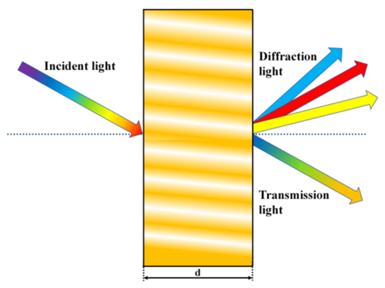
A VPHG is a type of holographic grating recorded within the bulk of a photosensitive material. Unlike surface-relief gratings, the grating structure of a VPHG exists throughout the three-dimensional volume of the material, where periodic modulation of the refractive index enables spectral separation. This configuration offers superior diffraction efficiency and enhanced angular selectivity. As illustrated in Figure 1, the grating is formed through the interference of two recording beams within the photosensitive medium. The parameter d represents the thickness of the photosensitive recording layer.
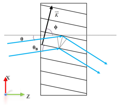
VPHGs are based on holographic technology, and their operating principle can be divided into two stages: wavefront recording and reconstruction [27]. Wavefront recording is governed by interference theory. When two or more coherent light beams carrying amplitude and phase information intersect, they interfere to form fringe patterns. These patterns induce physical or chemical changes in the recording medium, which, after subsequent processing, result in spatially modulated refractive index variations. Wavefront reconstruction is governed by diffraction theory. The dispersive effect of the VPHG is based on the Bragg diffraction principle, as illustrated in Figure 2. Here,  θ  denotes the incident angle of the incoming light within the recording medium,  θ B  represents the Bragg angle (the angle between the incident light and the fringe planes), and K is the grating vector with magnitude  K = 2 π / Λ φ  is the fringe slant angle, representing the angle between the fringe planes and the grating surface. This principle involves constructive interference of light scattered from equally spaced fringe planes in specific directions. In VPHGs, this manifests as incident light waves being scattered by different grating layers; when these scattered waves add coherently in phase, the intensity of the diffracted light reaches a maximum. This diffraction phenomenon can be described by the Bragg condition, which in its general form is expressed as
cos ( φ θ ) = K 2 β
Here,  β  denotes the propagation constant of the incident light wave, defined as  β = 2 π / λ . When  φ  equals 90°, the VPHG is a transmission-type grating with non-slanted fringes, and the Bragg condition can be simplified as follows:
2 n a v e Λ sin θ B = λ B
Here,  λ B  is the Bragg wavelength,  n a v e  is the average refractive index of the grating material, and Λ is the grating period. Under this condition, the effect of fringe slant angle on the grating can be neglected [28,29].
When a VPHG is used in a CO2-detection imaging spectrometer, its diffraction spectrum corresponds to the infrared absorption bands of CO2. However, photosensitive recording materials typically exhibit poor sensitivity in the infrared range, making it difficult to perform interference recording and diffraction reconstruction directly at these wavelengths. Therefore, the principle of wavelength-shifted reconstruction is adopted: by using a different wavelength and adjusting the original Bragg angle, the vector difference between the incident and diffracted beams can be made equal to the grating vector recorded earlier. Under this condition, the Bragg condition is still satisfied, and the diffracted light reaches maximum intensity. For VPHGs designed for CO2 detection, certain grating parameters can be calculated based on application requirements and grating theory. Taking a transmission-type VPHG with non-slanted fringes as an example, the relevant equations—namely, the grating equation, the linear dispersion equation of the spectrometer, and the Bragg condition—can be used to derive the following expression:
tan θ B = c s λ B 2 A f
Here,  c s  denotes the pixel size of the detector,  A  represents the spectral resolution, and  f  is the focal length of the focusing mirror. Given the required spectral resolution, the focal length of the focusing mirror, and the detector specifications, the corresponding Bragg angle can be calculated, and the grating period can be determined based on the Bragg condition.

2.2. Diffraction Theory

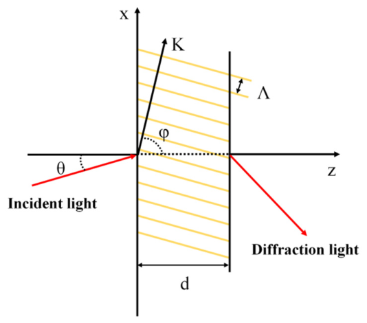
The diffraction characteristics of VPHGs are analyzed using optical diffraction theory, which can be categorized into scalar and vector diffraction theories. Scalar diffraction theory is an approximate model suitable for gratings with periods significantly larger than the wavelength. Although computationally efficient, it offers limited accuracy and is not applicable to VPHGs. Vector diffraction theories include Kogelnik’s coupled-wave theory [30], thin grating analysis theory, beam propagation methods, rigorous modal theories, rigorous coupled-wave analysis (RCWA) [31], and finite-difference time-domain (FDTD) methods [32]. Among these, RCWA and Kogelnik’s coupled-wave theory are most commonly used for analyzing the diffraction characteristics of VPHGs. However, RCWA involves a computationally intensive process, requiring the solution of N-order coupled-wave equations. Consequently, it is time-consuming and computationally demanding for diffraction analysis. In contrast, Kogelnik’s coupled-wave theory applies simplifying assumptions when constructing the model, which reduces the computational complexity. Its accuracy remains comparable to that of rigorous coupled-wave theories while offering significantly higher computational efficiency. Therefore, this study primarily adopts Kogelnik’s coupled-wave theory for analysis. The theoretical model is illustrated schematically in Figure 3.
Kogelnik’s coupled-wave theory is a classical theoretical model for analyzing the diffraction characteristics of VPHGs. It was originally proposed by Herwig Kogelnik in 1969. The theory is founded on the propagation of electromagnetic waves in periodic media. It incorporates the incident and diffracted waves, along with the spatial modulation of the refractive index, to derive a set of coupled differential equations between the incident wave and the first-order diffracted wave using Maxwell’s equations. By solving these equations using their general solutions and applying appropriate electromagnetic boundary conditions, the spatial field distribution of the first-order diffracted wave is obtained. The diffraction efficiency of the first-order diffracted light can subsequently be calculated. Taking a non-absorbing, transmission-type VPHG with non-slanted fringes as an example, the diffraction efficiency for different polarization states can be calculated using the following expressions:
η = sin 2 ν 2 + ξ 2 1 2 1 + ξ 2 ν 2
ν T E = π Δ n d λ B cos θ B
ν T M = π Δ n d cos 2 θ B λ B cos θ B
ξ = Δ θ K d 2 Δ λ K d 8 π n a v e cos θ B
In these expressions,  ν T E  and  ν T M  represent the coupling coefficients for the  T E  and  T M  polarization states, respectively, and are related to the modulation depth of the grating.  ξ  is the detuning parameter, which reflects the deviation from the Bragg condition. The wavelength and angular bandwidths corresponding to the half-maximum diffraction efficiency can be expressed as
λ F W H M = λ B Λ cot θ B 2 d
θ F W H M = Λ 2 d

3. Multi-Objective Grating Design Based on Simulated Annealing

VPHGs can be classified in various ways based on their structural and physical properties. Based on their modulation effect on incident light, they are categorized into amplitude-type and phase-type gratings. Based on the recording geometry, they can be categorized as transmission-type or reflection-type. Additionally, based on the fringe slant angle, they are classified as slanted-fringe or non-slanted-fringe types [33]. Theoretically, phase-type VPHGs can achieve diffraction efficiencies approaching 100%. By comparing the theoretical diffraction performance and fabrication tolerances of various grating types, it is observed that transmission-type VPHGs exhibit wide spectral bandwidth but narrow angular bandwidth. In contrast, reflection-type VPHGs exhibit superior angular selectivity but strong wavelength selectivity, making it challenging to cover the required spectral range for detection. Furthermore, during thermal expansion and contraction, reflection-type VPHGs may experience non-uniform fringe spacing along the thickness direction. For slanted-fringe VPHGs, the central wavelength of peak performance shifts; however, the spectral bandwidth, angular bandwidth, and peak diffraction efficiency remain essentially unchanged. Additionally, precise control of the fringe slant angle during thermal expansion and contraction processes is challenging. Therefore, this study focuses on non-slanted fringe transmission-type VPHGs, whose theoretical performance satisfies the requirements for CO2 detection. Furthermore, the fabrication process conditions and grating parameters for gratings are relatively controllable.

3.1. Multi-Objective Simulated Annealing Method for VPHG Design

The development of VPHGs can be divided into design and fabrication stages. Traditional VPHG design methods simulate the effects of varying grating parameters on diffraction performance using diffraction theory. By iteratively adjusting these parameters, an optimal design is sought; this approach is known as “forward grating design”. However, this method suffers from slow convergence, low computational efficiency, and does not guarantee globally optimal solutions. For VPHGs in CO2 detection applications, the theoretical design must meet stringent requirements to enable the spectrometer to achieve high spectral resolution, high signal-to-noise ratio, and high operational efficiency. This necessitates that the VPHG simultaneously possess excellent dispersion capability, high diffraction efficiency, low polarization sensitivity, and a spectral bandwidth covering the CO2 absorption peaks. However, traditional design methods struggle to simultaneously optimize diffraction efficiency, spectral bandwidth, polarization sensitivity, and other performance parameters, making it difficult to meet application requirements across all diffraction characteristics. Therefore, to address the challenges in designing transmission-type VPHGs with high dispersion capability in the short-wave infrared region, this study proposes a design method based on Kogelnik’s coupled-wave theory combined with a multi-objective simulated annealing algorithm. Grounded in the concept of “inverse grating design”, this method delivers accurate computational results with high efficiency and enables the balanced optimization of multiple diffraction performance parameters.
The design of VPHGs represents a combinatorial optimization problem characterized by a rapidly expanding search space. Consequently, finding the optimal design through exhaustive enumeration becomes computationally infeasible, necessitating the incorporation of metaheuristic optimization algorithms in the design process [34]. Metaheuristic algorithms are commonly employed to address such combinatorial problems. After comparing various optimization methods, this study ultimately selected simulated annealing as the optimization tool [35]. Inspired by the metallurgical annealing process, simulated annealing avoids local optima by probabilistically accepting inferior solutions. Although its computational implementation is relatively straightforward, the slow convergence issue can be mitigated by tuning annealing parameters and algorithmic settings, enabling faster identification of the global optimum among multiple local optima. Since simultaneous optimization of multiple diffraction performance parameters is required in grating design, this study extends the optimization algorithm using a multi-objective fitness function approach to accommodate the specific requirements of VPHG design [36]. By designing appropriate fitness functions that balance the relationships among multiple objective functions, multi-objective optimization is effectively transformed into an approximate single-objective optimization problem.
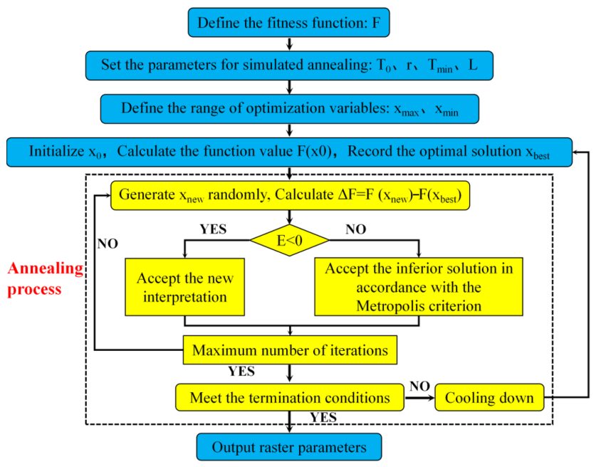
The optimization process of the algorithm is illustrated in Figure 4 and essentially consists of a nested two-level loop structure. The outer loop controls the temperature, which decreases gradually from high to low, while the inner loop maintains a fixed temperature and performs multiple iterations to search for optimal solutions. During optimization, annealing parameters and optimization variables are first specified [37]. An initial parameter set is randomly generated within the variable range, and its fitness value is calculated based on the defined fitness function. This parameter set and its corresponding fitness value are designated as the initial optimal solution. Subsequently, at the initial temperature, the algorithm enters the Markov chain iteration phase. A new solution is randomly generated, and its fitness value is calculated. By comparing it with the current optimal solution, either an improvement is accepted or a worse solution is probabilistically accepted, and the new solution is set as the updated optimal solution. When the maximum number of iterations is reached, the iteration at the current temperature terminates. The temperature is then decreased to proceed with the next cycle. This process continues until the temperature falls below the predefined cutoff value, at which point the algorithm terminates and outputs the optimal design solution.
For VPHGs applied in CO2 detection spectrometers, the detection spectral range corresponds to the gas’ infrared absorption spectrum. This study selects a wavelength range of 1.620–1.650 μm with a central wavelength of 1.635 μm. Furthermore, studies have demonstrated that a spectral resolution of 0.1 nm for the detection payload enables high-precision gas concentration retrieval, which imposes specific requirements on the detector and focusing lens parameters within the spectral imaging system. Commonly employed detector pixel sizes range from 15 to 35 μm, while the focal length of the imaging lens typically ranges from 100 to 300 mm. According to calculations, the Bragg angle and grating period for the grating design range from 22.23° to 67.82° and 0.5809 μm to 1.4214 μm, respectively. Additional grating design parameters include grating thickness and refractive index modulation depth, whose ranges must be determined based on the diffraction characteristics of the VPHG and practical fabrication constraints. Due to limitations in experimental fabrication capabilities, the maximum refractive index modulation depth is set to 0.06, with an optimization range of 0.01–0.06. Considering that excessive grating thickness increases material absorption, the thickness range is selected as 1–80 μm. The above parameter ranges define the variable search space for grating design. VPHGs designed within these ranges can satisfy the application requirements for detection, serving as the variable space for algorithmic optimization.
When developing the optimization program, it is necessary to consider the specific settings of the annealing algorithm, including annealing parameters, optimization variable settings, methods for generating initial and new solutions, and the definition of the multi-objective fitness function. The parameters of the simulated annealing algorithm include the initial temperature (T0), termination temperature (Tmin), annealing rate (r), and Markov chain length (L). These parameters significantly affect the algorithm’s convergence and computational efficiency. Additionally, the initial temperature affects the probability of escaping local optima. Considering these factors, the values are set as T0 = 1000 °C, Tmin = 0.0001 °C, r = 0.985, and L = 800. The grating design parameters include grating thickness, refractive index modulation depth, grating period, and Bragg angle. However, since the grating period and Bragg angle are strongly correlated and can be calculated using Equation (2), only three independent optimization variables remain in the final design. The initial solution is obtained by adding the product of the variable ranges and random numbers to the lower bounds, ensuring the result lies within the variable ranges. When generating new solutions, perturbations are applied in the vicinity of the current solution, with the perturbation magnitude dependent on the current temperature and constrained within the optimization variable bounds.
The optimization objective of this study is to design a high-performance VPHG for CO2 detection applications. Therefore, the fitness function is defined based on specific diffraction performance requirements. For gratings used in CO2 detection, high diffraction efficiency, adequate bandwidth covering the spectral range requirements, and low polarization sensitivity are essential. Accordingly, these performance criteria are incorporated as constraints within the fitness function to achieve a global optimum. Specifically, diffraction efficiency and bandwidth calculation formulas derived from Kogelnik’s coupled-wave theory are used. High diffraction efficiency is ensured by constraining the diffraction efficiency at the central wavelength and at the spectral range’s edge wavelengths under different polarization incidence conditions. Broadband performance is achieved by constraining diffraction efficiency and spectral bandwidth at the edge wavelengths. Polarization insensitivity is achieved by constraining polarization sensitivity at three strategically selected wavelengths. The combination of the above constraints forms the fitness function F, defined as follows:
F = a 1 b 1 + a 2 b 2 + a 3 b 3 + + a 10 b 10 10
a 1 = 1 sin 2 ( π Δ n d 1.635 cos θ B ) , a 2 = 1 sin 2 ( π Δ n d cos 2 θ B 1.635 cos θ B )
a 3 , 5 = 1 sin 2 ( ν T E 2 + ξ 2 ) 1 2 1 + ξ 2 ν T E 2 , Δ θ = 0 , Δ λ = 1.62 , 1.65
a 4 , 6 = 1 sin 2 ( ν T M 2 + ξ 2 ) 1 2 1 + ξ 2 ν T M 2 , Δ θ = 0 , Δ λ = 1.62 , 1.65
a 7 = d cot θ B Λ λ B
a 8 = a 1 a 2 2 , a 9 = a 3 a 4 2 , a 10 = a 5 a 6 2
Here,  F  represents the fitness function;  a 1  and  a 2  constrain the diffraction efficiency at the central wavelength;  a 3  and  a 4  constrain the diffraction efficiency at the 1.620 μm edge wavelength;  a 5  and  a 6  constrain the diffraction efficiency at the 1.650 μm edge wavelength;  a 7  constrains the spectral bandwidth; and  a 8 a 9 , and  a 10  constrain the polarization sensitivity. The coefficients  b 1  through  b 10  represent the weights assigned to each optimization objective, which sum to unity. Detailed weight values are provided in Table 1. The simulated annealing algorithm’s ability to escape local optima primarily relies on the Metropolis acceptance criterion. According to this criterion, a worse solution is accepted with probability  P = exp Δ F / T  when  P  exceeds a randomly generated number between 0 and 1, enabling global optimization. At high temperatures, the algorithm permits acceptance of larger deteriorations in the fitness function, whereas at low temperatures, only minor deteriorations are accepted. This necessitates that the ratio between the maximum fitness function difference and the initial temperature should not be too large, otherwise, insufficient acceptance of worse solutions may hinder convergence and cause the algorithm to get trapped in local optima. Calculations show that the maximum difference in the fitness function  F  is 4.29, and with an initial temperature of 1000, the acceptance criterion is satisfied.

3.2. Performance Analysis and Comparison of VPHGs

Using the proposed multi-objective simulated annealing design method, a VPHG suitable for CO2 detection applications was successfully designed. The optimized design results are presented in Table 2. The multi-objective fitness function converged to an optimal value of 0.6125. The corresponding optimal grating parameters are: a thickness of 32 μm, a refractive index modulation of 0.06, a Bragg angle of 35.002°, and a grating period of 0.9376 μm.
Based on the VPHG design results, the grating’s diffraction performance can be theoretically analyzed. This study focuses on several key aspects of VPHG performance: wavelength and angular selectivity under TE and TM polarization, polarization sensitivity, wavelength selectivity under unpolarized light, and the full width at half maximum (FWHM) spectral bandwidth under different polarization states. Polarization sensitivity is defined as the absolute difference in diffraction efficiency between TE and TM polarizations at the same wavelength of incidence. The diffraction efficiency for unpolarized light is defined as the average of the efficiencies under TE and TM polarization. The corresponding mathematical definitions are as follows:
S = η T E η T M 2
η un = η T E + η T M 2
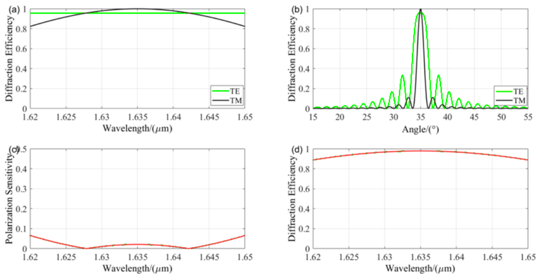
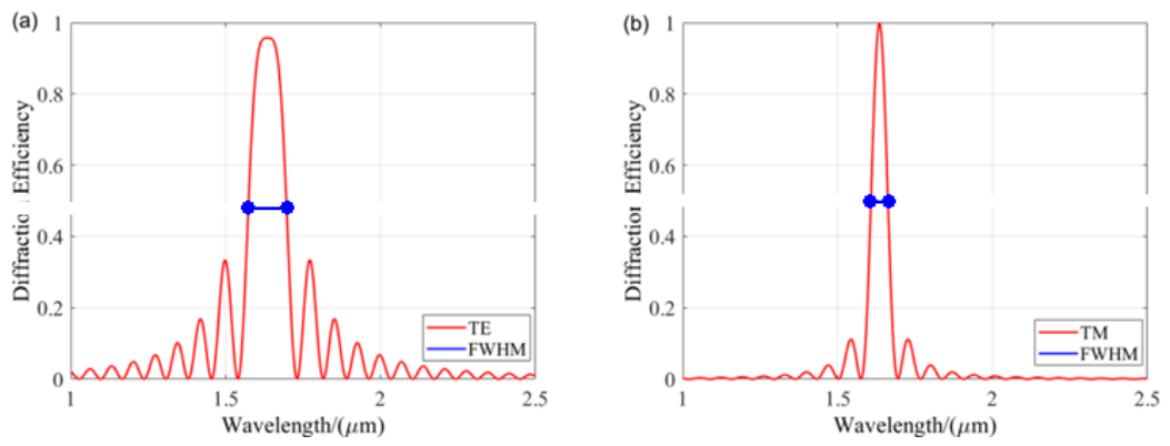
Here,  S  denotes the polarization sensitivity,  η u n  is the diffraction efficiency for unpolarized light,  η T E  is the diffraction efficiency under  T E  wave incidence, and  η T M  is the diffraction efficiency under  T M  wave incidence. Figure 5 presents the calculated diffraction performance of the grating designed using the multi-objective simulated annealing algorithm. The simulation results are based on Kogelnik’s coupled-wave theory. The results demonstrate that the designed VPHG achieves a diffraction efficiency exceeding 95.35% under TE polarization across the spectral range, with a full angular width at half maximum (FAWHM) of 3°. Under TM polarization, the diffraction efficiency exceeds 82.21%, with an FAWHM of 1.3°. The polarization sensitivity remains below 6.57%, and the diffraction efficiency for unpolarized light exceeds 88.78% across the target spectral range, demonstrating excellent overall performance. Figure 6 illustrates the simulated spectral bandwidth characteristics of the designed grating. Under TE polarization, the full width at half maximum (FWHM) spectral bandwidth reaches 122 nm, while under TM polarization, the FWHM reaches 54 nm.
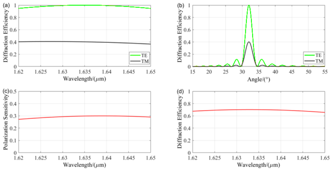
To further validate the advantages of the proposed design method, a comparative analysis was conducted by designing a short-wave infrared VPHG under identical application conditions and performance requirements using VirtualLab Fusion 2021—a commercially available optical design platform. In this software, diffraction performance is calculated primarily using RCWA and optimization is performed using a conventional single-objective simulated annealing algorithm. The resulting grating parameters include a grating period of 1.0141 μm, a Bragg angle of 32.03°, a grating thickness of 20.615 μm, a refractive index modulation of 0.0336, and an average refractive index of 1.52. Based on these parameters, diffraction performance analysis was conducted, with results shown in Figure 7. The VirtualLab-designed VPHG exhibits a TE-polarization diffraction efficiency exceeding 94.6% across the spectral range, with a peak efficiency of 100%. However, the diffraction efficiency for TM polarization drops to 34.58% at the spectral edge, with a peak value of only 40.3%. The maximum polarization sensitivity reaches 29%, and the diffraction efficiency under unpolarized light remains above 65.6%, indicating that the overall diffraction performance does not meet the stringent requirements for CO2 detection applications. In contrast, the proposed multi-objective simulated annealing method enables balanced optimization of diffraction efficiency, spectral bandwidth, and polarization sensitivity simultaneously. This method enables application-specific design and overcomes the performance limitations of conventional single-objective approaches. It significantly improves computational performance, achieving approximately 80% reduction in design time compared to conventional methods. Furthermore, it exhibits superior convergence behavior, enabling rapid and stable identification of the global optimum. The strong robustness of this method effectively prevents convergence to local optima in high-dimensional design spaces, offering a practical solution for VPHG designs with demanding multidimensional performance requirements. It also provides valuable theoretical guidance for VPHG fabrication.


4. Fabrication of Transmission-Type VPHGs

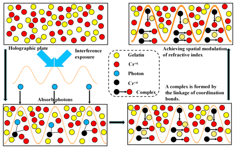
Based on the VPHG design method proposed in Section 3, theoretical grating parameters suitable for CO2 detection applications have been obtained. The subsequent step involves using these theoretical parameters as the foundation for fabricating the VPHG. In response to the requirements of CO2 imaging spectrometers and considering the standard aperture size of dispersive gratings used in current Earth observation satellites, this study focuses on the fabrication process of medium-to-large aperture (100 mm) VPHGs, aiming to evaluate their feasibility for practical applications in greenhouse gas monitoring. VPHGs are a class of thick holographic gratings that can be fabricated using various recording materials, including silver halide emulsions, dichromated gelatin (DCG) [38,39], photorefractive crystals, photoresists, photopolymers [40,41], and photothermal plastics [42]. The choice of recording material significantly influences the resulting diffraction performance and fabrication process. In this study, DCG was selected as the recording material due to its high spatial resolution, wide dynamic range of refractive index modulation, negligible infrared absorption, and uniform dispersion characteristics, which provide significant advantages for the fabrication of high-performance short-wave infrared VPHGs. The DCG material comprises a gelatin solution, a dichromate photosensitizer solution, and a chromium potassium sulfate hardening solution. The dichromate acts as the photosensitizer that enables recording of the grating structure, while chromium potassium sulfate serves as a hardening agent that stabilizes the latent image. The internal grating formation mechanism is primarily based on photochemical reactions, as illustrated schematically in Figure 8. During exposure, the gelatin layer absorbs photon energy, triggering photochemical reactions in the exposed regions (corresponding to bright interference fringes). Hexavalent chromium ions (Cr6+) are photoreduced to tetravalent chromium ions (Cr4+), which are unstable and form coordination complexes with the remaining Cr6+ ions. This increases the cross-linking density and reduces the water solubility of the exposed areas. In contrast, the unexposed (dark fringe) regions remain chemically unchanged. The differences in hardness and solubility between these regions lead to variations in refractive index modulation, thereby forming a volume holographic grating structure [43].
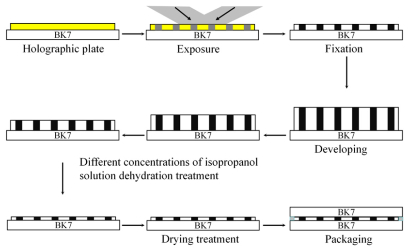
The grating fabrication process using DCG material consists of three main stages: holographic plate preparation, interference recording exposure, and post-processing, as illustrated in Figure 9. The plate preparation stage primarily produces a photosensitive film capable of recording the VPHG structure, while the interference exposure stage records the latent grating image in the film according to the designed grating period and Bragg angle. The post-processing stage comprises five steps: fixing, aqueous development, dehydration development, drying, and encapsulation. This process stabilizes the latent grating image and controls the refractive index modulation and grating thickness, ultimately producing a VPHG with enhanced environmental stability through protective encapsulation [44]. This study focuses on the fabrication process of 100 mm aperture VPHGs, as conventional methods developed for small apertures (≤50 mm) are unsuitable for large-aperture fabrication. For VPHG fabrication, it is essential to ensure uniform film thickness and adequate initial hardness during the plate preparation stage. The interference exposure requires a high-quality large-aperture interference field, and the alignment of the large-aperture exposure system poses significant challenges, necessitating strict control of process conditions. During post-processing, uniform treatment across the full aperture and thorough internal chemical reactions are required, with process parameters strictly controlled to regulate the final grating characteristics. To address these challenges, this work presents a comprehensive study on the fabrication process of 100 mm aperture short-wave infrared VPHGs.

4.1. Preparation of DCG Plates

DCG is a well-established volume holographic recording material with a mature fabrication process. The resulting holographic plates exhibit the characteristics of pure phase holograms. When the fabricated plates meet the required specifications and subsequent processing steps are properly executed, a well-defined spatial modulation of the refractive index can be formed within the gelatin layer, resulting in a VPHG with high diffraction efficiency. Due to the hygroscopic nature of DCG plates, their chemical properties are highly sensitive to ambient humidity, making them unsuitable for long-term storage when fabricated in large batches. Considering the experimental conditions and fabrication requirements, this study adopted a photosensitive gelatin solution coating method for plate preparation. This method is straightforward, allows flexible control of solution concentration and film thickness, and is cost-effective. DCG plates were freshly prepared prior to each exposure, eliminating the requirement for long-term storage. This method consists of five main steps: material selection, solution preparation, substrate selection and cleaning, gelatin coating, and aging/drying. The entire process was conducted in a darkroom under red safe light illumination. The detailed procedure was as follows:
(1) Material Selection: For the preparation of DCG plates in this study, chemically pure gelatin (500 g, CP grade) and potassium chrome alum dodecahydrate (500 g), both obtained from Sinopharm Chemical Reagent Co., Ltd. (Shanghai, China), were used as the gelatin base and hardener, respectively. The photosensitizers were prepared as aqueous solutions of potassium dichromate and ammonium dichromate at concentrations of 10% and 20% (w/v), respectively.
(2) Solution Preparation: A total of 5.5 g of gelatin granules was weighed using an electronic balance and dispersed in 100 mL of deionized water. The mixture was left to stand for 30 min, then transferred to a thermostatic water bath at 70–80 °C and stirred with a glass rod for 20 min to obtain a gelatin solution. Separately, 20% ammonium dichromate solution and 2% potassium chrome alum solution were prepared using the same procedure. The water bath was then adjusted to 50 °C, and the three solutions were mixed in a ratio of 40:1:6 (gelatin:chrome alum:ammonium dichromate) to form the photosensitive gelatin solution. Immediately prior to coating, a precision syringe was used to extract the required volume of solution.
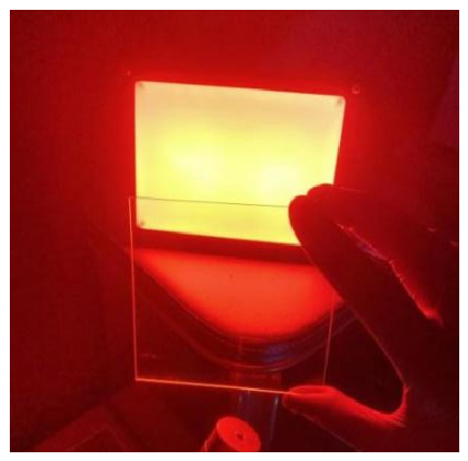
(3) Selection and Cleaning of Substrate Glass: BK7 optical glass with dimensions of 100 × 100 × 2 mm was selected as the substrate for the holographic plate. This material exhibits negligible absorption in the infrared spectral region and has a refractive index closely matched to that of the DCG layer. For cleaning, the glass substrates were first subjected to ultrasonic cleaning in deionized water to remove surface particulates, followed by ultrasonic cleaning in ethanol to eliminate organic contaminants. The substrates were then rinsed with fresh deionized water and gently wiped with lint-free tissue. Finally, they were dried in a convection oven and stored in a cleanroom environment. As shown in Figure 10, the cleaned glass substrates exhibited smooth and clean surfaces, high optical transmittance, and were free of dust and impurities.
(4) Coating of Photosensitive Gelatin Solution: Considering the laboratory conditions, the blade-coating method was adopted for applying the photosensitive gelatin solution. The coating process was performed by placing the coating plate on a 70 °C heated platform and positioning the cleaned BK7 substrate on top. A measured volume (3.3 mL), calculated based on the substrate area and target grating thickness, of the DCG solution was withdrawn from a 50 °C thermostatic water bath and deposited onto the substrate. The solution was then rapidly spread evenly using a calibrated coating blade. Immediately after coating, the heating platform was deactivated. The coated substrate was left undisturbed for 10 min to allow air bubbles to dissipate naturally and to take advantage of the enhanced fluidity of the photosensitive solution at 40 °C. Once leveled by surface tension forces, the desired DCG dry plate was obtained.
(5) Drying and Aging: Traditionally, the aging process involves air-drying the coated plates for 2 h in a dark environment maintained at 20 °C and relative humidity below 30%, followed by curing in a thermostatic drying oven at 40 °C for an additional 2 h. However, dry plates prepared using this method exhibited a thickness of approximately 29.84 μm with poor uniformity (∼10.91%) and were prone to film delamination during subsequent processing, primarily due to insufficient initial hardness. To address these issues, this study developed an improved aging procedure. The dry plates were first pre-dried in a dark environment and then subjected to a controlled gradual temperature ramping process for final aging. The total aging duration was extended to 4 h to ensure complete solvent removal and proper film hardening. Measurements showed that the improved method yielded dry plates with an average thickness of approximately 29.17 μm and enhanced uniformity of around 4.64%, meeting the requirements for plate fabrication and demonstrating significantly improved performance compared to the conventional method.
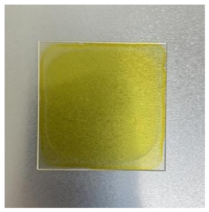
The final DCG dry plates, shown in Figure 11, exhibited reduced thickness uniformity at the edges, while the central area (approximately 90 × 90 mm) demonstrated good uniformity suitable for grating fabrication. A total of 20 dry plates were prepared and characterized for grating fabrication. Due to the sensitivity of the material to light, humidity, and temperature, the dry plates were wrapped in ultra-fine dust-free cloth and stored in light-tight sealed containers with desiccants. These containers were stored in a refrigerator at 4 °C. Under these conditions, the plates remained stable for 6–8 months without significant degradation of material properties.

4.2. VPHG Recording and Exposure System

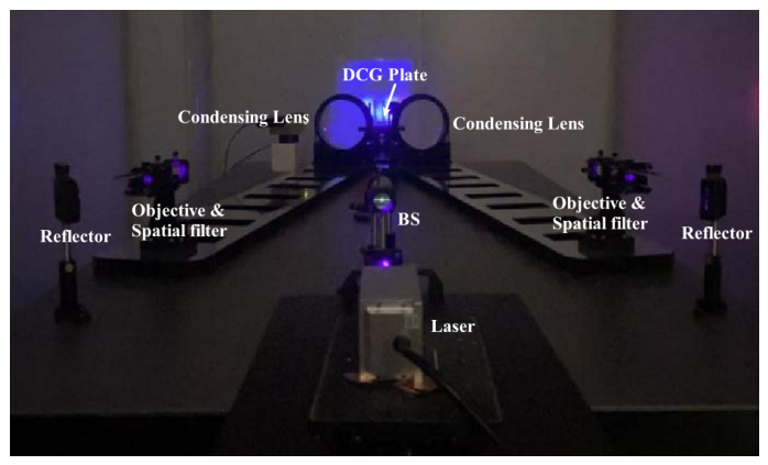
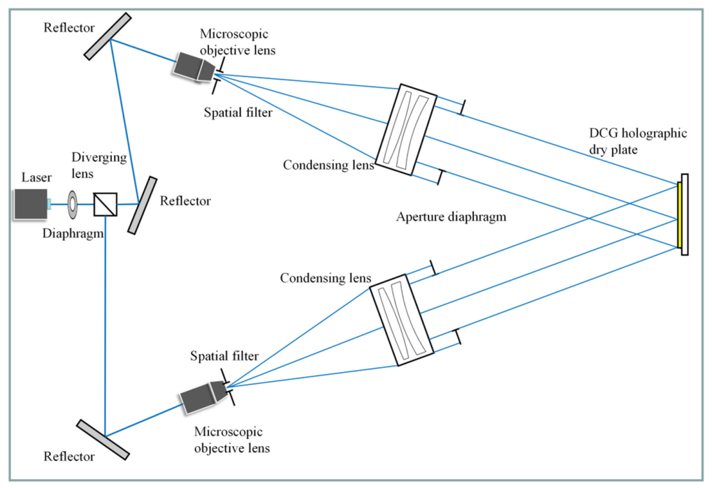
The second stage in VPHG fabrication involves exposure using an interference pattern. This study employed a single static interference exposure method with amplitude-splitting transmission geometry. The overall system, shown in Figure 12, comprises a laser light source, spatial filter, beam-splitting element, reflective components, and two collimated beam expansion arms. Each collimation and expansion arm includes a microscope objective, spatial filter, beam expander lens, and aperture. The specifications of each component in the exposure system were determined by the properties of the recording material and the target grating parameters. Based on the spectral sensitivity characteristics of DCG, a 405 nm diode-pumped solid-state laser with high photosensitivity was selected as the exposure light source. Measurements show the laser emits monochromatic, linearly polarized light at 405.14 nm, with a maximum power of 67.5 mW, a beam diameter of 1.3 mm, divergence of less than 1.5 mrad, power stability of 0.346%, and a coherence length exceeding 1 m. The beam-splitting element was a non-polarizing beam splitter cube with a measured splitting ratio of 49.9:50.1, ensuring balanced interference beam intensities and high fringe contrast. The reflectors employed were PF10-03-F01 from Thorlabs (Newton, NJ, USA), with a measured reflectivity of approximately 93.26%, satisfying the system requirements. The microscope objective is Newport’s M-series (Newport Corporation, Irvine, CA, USA), covering a wavelength range of 400–700 nm, with a numerical aperture of 0.25 and an effective focal length of 16.5 mm. The spatial filter primarily removes high-frequency spatial noise, producing a cleaner focused beam. This ensures that the expanded interference field meets the exposure requirements. Considering the objective parameters and pinhole diffraction effects, a 10 μm diameter spatial filter was selected.
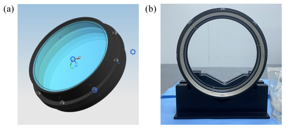
High-quality interference fields are critical during VPHG exposure, requiring the system to output plane waves with excellent wavefront quality and uniformity. Given the 100 mm grating size, the plane wave aperture produced by the beam expander must exceed 1.25 times the recorded interference field diameter to ensure uniform illumination and field quality. Based on this requirement, a 180 mm clear aperture was selected for the beam expander. However, commercial optical components typically cannot simultaneously meet both the aperture size and optical quality requirements, necessitating custom design and fabrication of the beam expander lens. Based on the microscope objective’s numerical aperture and specifications, the beam expander lens was designed with a focal length of 1440 mm. The complete optical design was performed using Zemax OpticStudio software. Fused silica (SiO2) was selected as the optical material, and a two-element lens group structure was adopted, optimizing primarily for spherical aberration and wavefront quality. The final lens design achieved a focal length of 1441.17 mm, F-number of 7.98, entrance pupil diameter of 180 mm, exit pupil diameter of 187.45 mm, and back focal length of 1459.88 mm. The RMS wavefront errors of the resulting plane wave were 0.0002λ, 0.0013λ, and 0.0025λ at normalized field positions of 0, 0.707, and 1.0, respectively. All physical parameters and performance metrics satisfied the design requirements. Tolerance analysis indicated a worst-case wavefront deviation of 0.03λ, confirming the manufacturability of the design. Manufacturing specifications required a surface figure accuracy better than λ/60, with an anti-reflective coating applied to achieve transmission exceeding 99% across the 380–420 nm wavelength range. The lens mechanical structure was based on Zygo interferometer standard lens mounts (Zygo Corporation, Middlefield, CT, USA), with aluminum selected as the structural material. The lens mount employed a separable flange connection design. For the two elements in the lens group, two mounts were assembled and adjusted via precision screw holes, screws, and shims, allowing precise control of the element spacing by adjusting shim thickness. The lens elements are bonded to the mounts using a single-component silicone adhesive, RTV-157, applied via a dispenser at eight points on the mount’s side. Figure 13a shows the mechanical design of the mount, while Figure 13b presents the assembled and adjusted beam expander lens.
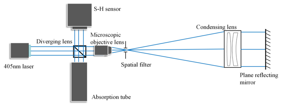
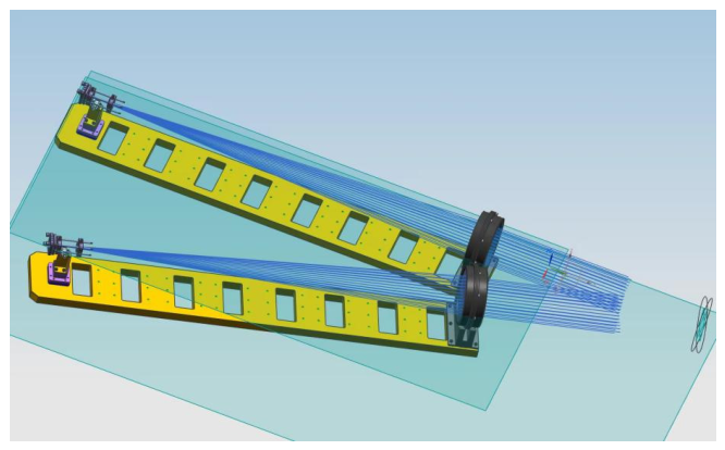
Prior to exposure, each collimation system was individually adjusted to produce the required fringe spacing. Using a dispersed optical layout would complicate this process and necessitate repeated realignments for different fringe periods. To address this challenge, we developed an integrated, lightweight mechanical structure for the exposure system, shown in Figure 14. It features a single-piece hollow aluminum base, a beam expander lens mount, and a cage system supporting the microscope objective and spatial filter. This integrated design accommodates various grating periods and significantly simplifies the adjustment process.
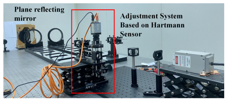
The stringent requirements for interference fringe quality and uniformity during exposure impose strict demands on the wavefront quality of each plane wave arm and the angular correlation between the two exposure beams. These requirements introduce significant technical challenges in the overall alignment of the exposure system. Traditional precision optical alignment often relies on Zygo interferometers; however, since these instruments operate at fixed, narrow-band wavelengths (typically He-Ne laser at 632.8 nm), they are ill-suited for alignment of the 405 nm recording exposure system used in this study. The significant wavelength mismatch can introduce alignment inaccuracies due to chromatic effects. Furthermore, the system produces a large 180 mm aperture collimated beam, resulting in a physically large setup. Using a Zygo interferometer would substantially complicate the alignment process and contradict the goals of optical path reuse and adjustment simplicity. To address this challenge, we propose a precision alignment method for recording exposure systems based on an integrated Hartmann wavefront sensor [45]. The alignment setup is shown in Figure 15 and incorporates a beam splitter, Hartmann wavefront sensor, and beam block connected via a cage structure and precision adjustment mount. The sensor employed is the OPTOCRAFT SHR4-130-GE (OPTOCRAFT GmbH, Erlangen, Germany), featuring a 10.3 mm detection area and an operating wavelength range from 355 to 1064 nm. It comprises a microlens array wavefront sensor offering high measurement accuracy, wide spectral measurement range, operational flexibility, and in situ measurement capability. During alignment, wavefront variations measured by the sensor guided the fine-tuning process, enabling iterative adjustments to achieve wavefront aberration levels satisfying the exposure requirements.
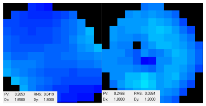
The alignment process consisted of two stages: coarse adjustment based on beam spot characteristics and fine adjustment guided by quantitative wavefront measurements. During coarse adjustment, the beam expander lens served as the optical reference. Adjustments were made to the optical axis, microscope objective position, spatial filter position, and spatial orientation according to changes in beam height, spot position, spot diameter, and brightness. Figure 16 illustrates the fine adjustment process of the collimated beam expander system using the Hartmann sensor. The laser beam passes through the beam splitter in the integrated system, with one portion reflected to the beam block and the other transmitted into the collimated beam expander. After reflecting off a rear mirror, the beam retraces its path, passes through the beam splitter again, and reflects into the Hartmann sensor, enabling measurement of the expanded plane wave wavefront. During alignment, the microscope objective and spatial filter were first removed from the optical path. A flat mirror was inserted to adjust the spatial orientation, aligning the light source with the optical axis. Next, the microscope objective was returned to its original position, and the beam splitter was inserted. The objective’s two-dimensional spatial orientation is adjusted so that the reflected and incident beams nearly overlap at the beam splitter, visible as a reflected spot. Fine translational adjustments minimized the spot size and maximized brightness, completing the optical path alignment. The integrated Hartmann sensor system was then placed in the beam path to collect wavefront data. Based on defocus and monochromatic aberrations, the objective’s position and orientation are finely tuned to minimize the wavefront RMS error, completing fine objective adjustment. Finally, the spatial filter was returned to its original position and adjusted to ensure the sensor received light with minimal wavefront aberration, completing fine-tuning of the single-path collimated beam expander. Figure 17 shows the measured plane wave wavefront after fine adjustment of the two paths (black dots indicate sensor microlenses that could not focus). Using the proposed Hartmann sensor-based precision alignment, the two collimated beam expanders achieved wavefront RMS errors of 0.0419λ and 0.0364λ (λ = 405 nm), with PV values of 0.2053λ and 0.2466λ respectively. This surpasses traditional interferometer-based alignments, which typically achieve RMS errors around 1/20λ, demonstrating superior alignment accuracy and better plane wave quality suitable for practical recording exposure.
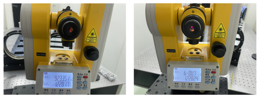
After separately aligning the two collimation systems, the exposure angles were adjusted according to the target grating period and recording wavelength. The calculated incidence angle for each beam was 12°28′21″. Using a precision theodolite with arcsecond resolution, the angles of both systems were finely adjusted. The final measured dual-beam incidence angles were 12°28′17″ and 12°28′24″, respectively, falling within the theoretical tolerance range, as shown in Figure 18. Finally, the beam splitter and reflectors were integrated into the optical path, enabling both collimated beam expanders to produce high-quality plane waves. Figure 19 shows the completed recording exposure system ready for grating fabrication.
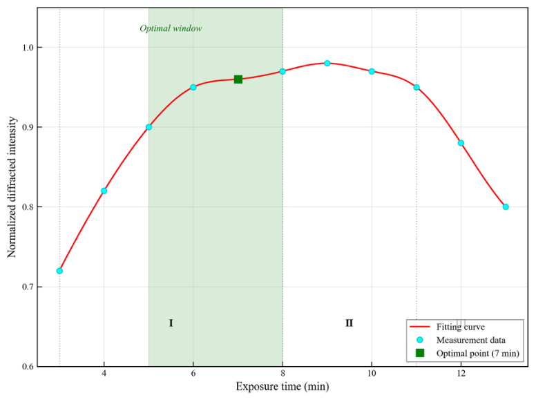
During VPHG exposure, photons are absorbed within the photosensitive film layer, inducing a photochemical reaction. Controlling the exposure dosage is critical in the recording process, as it directly affects the cross-linked structure that modulates the refractive index. The optimal exposure dosage was determined by monitoring changes in grating diffraction efficiency throughout the exposure process. The monitoring system consisted of a 632.8 nm He-Ne laser and a photodetector. According to Bragg’s condition, the incident angle of the 632.8 nm wavelength light is calculated to be 19.7214°. The probe laser was adjusted to this angle, and real-time power monitoring was performed during grating exposure. Figure 20 shows the final results: optimization of exposure time for holographic recording. The normalized diffracted intensity was measured as a function of exposure duration to determine the optimal recording parameters. The experimental data (cyan circles) were fitted using a cubic spline (red curve), revealing three distinct phases: Phase I (3–8 min) shows a monotonic increase in refractive index modulation as photopolymerization proceeds; Phase II (8–11 min) represents a saturation plateau approaching the material modulation limit (~0.98); Phase III (>11 min) exhibits degradation attributed to overexposure-induced scattering and reduced refractive index contrast. The optimal exposure window (green shaded region, 5–8 min) was determined based on the criteria of achieving >95% maximum efficiency while maintaining process stability. The exposure duration of 7 min (green square) was selected as the standard fabrication parameter, yielding a normalized intensity of 0.96 and providing a sufficient safety margin against the overexposure threshold.
A vibration-isolated experimental platform and a quiet environment are required during exposure. The process was conducted in a sealed, draft-free environment on an air-floating optical table. After mounting the dry plate, it was allowed to remain stationary for 5 min to ensure system stability. The laser was powered on in advance to allow stabilization of the light source, and the recording exposure was completed within the prescribed time according to the required exposure dosage. To ensure sufficient photochemical reaction and stabilization of the gelatin structure, the exposed dry plate was allowed to rest for 30 min, enhancing the effectiveness of the subsequent processing steps.

4.3. Post-Processing Procedure

After completing the recording exposure, the final stage in grating fabrication is the post-processing procedure. The post-processing of VPHGs mainly involves five steps: fixing, initial development, secondary development, drying, and encapsulation. The purpose of fixing is to remove unreacted chromium compounds, thereby increasing the hardness of the film layer with refractive index modulation formed after exposure. The initial development primarily involves aqueous washing; based on the principle that exposed areas absorb photons and undergo photochemical reactions leading to reduced water solubility, this differential solubility causes the gelatin to swell by absorbing water, enhancing the refractive index modulation while simultaneously washing away residual fixer from the film and substrate. Secondary development primarily employs dehydrating agents to extract water molecules from the swollen film layer. This process is analogous to drying, releasing residual water from the gelatin microporous structure as vapor, stabilizing the internal density variations in the film layer, further enhancing the refractive index modulation, and forming the final grating structure with spatially modulated refractive index. The initial post-processing method employed in this study was as follows:
(1) Fixing: Under room temperature and low humidity conditions, the grating was immersed in F5 fixer solution with gentle agitation of the container. The fixing time was 5–15 min.
(2) Aqueous Development: Under room temperature and low humidity conditions, the fixed grating was rinsed with deionized water for 5–15 min. The washing rate was carefully controlled during this process to ensure uniform development.
(3) Dehydration Development: Under room temperature and low humidity conditions, isopropanol solutions were prepared at concentrations of 50%, 70%, and 100%. The washed grating was first immersed in 50% isopropanol solution for 3 min, then transferred to 70% isopropanol for another 3 min, and finally placed in 100% isopropanol for 3–7 min for complete dehydration.
(4) Drying and Shaping: Residual liquid on the surface was removed using a stream of dry air at temperatures below 30 °C, maintaining an appropriate distance from the dry plate. Then, the grating was placed in a drying oven where the temperature was gradually increased to 90 °C and maintained for 30 min.
(5) Encapsulation: The grating layer was sealed with a cover glass made of the same material (BK7) and dimensions as the substrate glass to prevent moisture absorption and image degradation. This process was conducted under a relative humidity (RH) of less than 40%. The cover glass was fixed in position using optical-grade epoxy adhesive and allowed to fully cure over 24 h prior to storage.

5. Performance Measurement and Improvement in Post-Processing Procedures

5.1. Diffraction Efficiency Measurement System

When VPHGs are employed in various applications, their diffraction performance—including diffraction efficiency, angular selectivity, wavelength selectivity, and polarization sensitivity—directly affects their functionality and effectiveness within optical systems. This study primarily focused on measuring the diffraction efficiency of the fabricated gratings. Based on the measurement results, properties such as wavelength selectivity, spectral bandwidth, and polarization sensitivity were analyzed. The measurement targeted the absolute diffraction efficiency of the VPHG, defined as the ratio of diffracted optical power in a specific order to the incident optical power. The calculation formula is expressed as
η Absolute   diffraction   efficiency = P d i f f r a c t e d P incident × 100 %
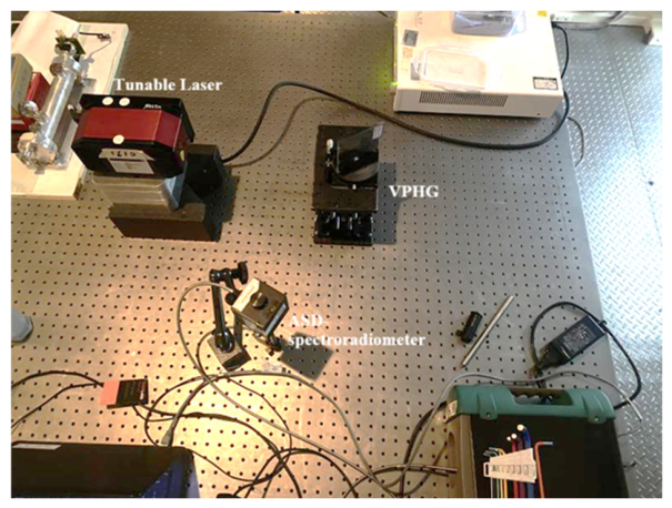
In the formula,  P d i f f r a c t e d  represents the power of the specific diffraction order, and  P i n c i d e n t  denotes the total power of the incident light. Traditional diffraction efficiency measurement systems typically employ a power meter to detect the signal; however, the results are often affected by ambient light interference and detector nonlinearity. Performing measurements in a darkroom is impractical for the infrared system used in this study due to the complexity of optical adjustments required. Therefore, this study employed an integrating sphere combined with an ASD FieldSpec spectroradiometer (Analytical Spectral Devices, Inc., Boulder, CO, USA) to detect the intensities of incident and diffracted signals. The system consisted of a tunable infrared laser covering the 1590–1630 nm range, a precision vertical translation stage, a precision rotation stage, a grating holder, an integrating sphere, and an ASD spectroradiometer. The overall setup was straightforward, the optical path was easy to configure, and the measurements were relatively accurate, enabling characterization of diffraction efficiency across different wavelengths and angles. During measurement, six wavelengths—1620 nm, 1622 nm, 1624 nm, 1626 nm, 1628 nm, and 1630 nm—are selected based on the tunable laser’s range. The rotation stage was adjusted to locate the angular position where the first-order diffracted light intensity reached its maximum. Once the optimal diffraction angle is located, the stage is fixed, and both the lifting platform and the grating’s axial position are adjusted. Diffraction efficiency was then measured at five positions: the grating center, top, bottom, left, and right edges. The variation in diffraction efficiency across these positions at the same wavelength is used to assess the uniformity of the grating’s performance and structure. Figure 21 shows the actual diffraction efficiency measurement setup.
After measurement, the first-order diffraction intensity at each incident wavelength was obtained. Based on the measured incident light intensity, the diffraction efficiency at different wavelengths was calculated. Subsequently, a diffraction efficiency–wavelength relationship curve for the fabricated VPHG was fitted using the measured data. This curve was used to analyze various diffraction characteristics, including peak diffraction efficiency at the central wavelength, spectral bandwidth, and polarization sensitivity. In this study, a nonlinear least squares method was employed to fit the experimental results. The core objective is to determine model parameters that minimize the sum of squared residuals between the model’s predictions and the experimental measurements. The fitting function is based on the diffraction efficiency equation derived from Kogelnik’s coupled-wave theory, which can be expressed as
η = sin 2 π 2 Δ n 2 d 2 λ B 2 cos 2 θ B + Δ λ 2 d 2 4 n a v e 2 cos 2 θ B Λ 2 1 2 λ B 2 Δ λ 2 4 π 2 Δ n 2 n a v e 2 Λ 2 + λ B 2 Δ λ 2
Based on the experimental measurement data, a total of six data pairs  Δ λ i ,   η i  are obtained. A nonlinear model  η = f Δ λ i ,   Δ n  is required, where  Δ λ  represents the wavelength deviation (independent variable),  η  is the nonlinear function representing diffraction efficiency (dependent variable), and  Δ n  is the model parameter to be optimized, representing the refractive index modulation. The subscript  n  denotes the data index, ranging from 1 to 6. The goal of the fitting process was to determine the optimal value of  Δ n  that minimizes the sum of squared residuals between the measured and fitted results. The objective function is expressed as
R S S = i = 1 6 η i f Δ λ i , Δ n
In this equation,  R S S  represents the residual sum of squares between the theoretical fit and the experimental measurements. Based on the above method, the wavelength selectivity curve of the VPHG was obtained through curve fitting. This curve enabled analysis of grating characteristics such as spectral bandwidth and polarization sensitivity.

5.2. Optimization of Post-Processing Conditions

Section 4 established the post-processing method adopted in this study; however, there remains room for improvement in specific process conditions. During fabrication, the complexity of the processing steps may result in deviations from the ideal grating structure, such as variations in fringe spacing or non-uniform modulation distribution. These imperfections cause the actual grating performance to deviate from the theoretically optimized parameters, affecting key properties such as diffraction efficiency and the central wavelength. Therefore, it is necessary to optimize the process conditions for grating fabrication to develop a post-processing procedure suitable for VPHG production. This study focused on optimizing three key parameters of the post-processing conditions: fixing time, rinsing time, and dehydration time in 100% isopropanol. Fixing time primarily affects the stabilization of the latent image and the hardening of the film layer, while rinsing and dehydration times influence the final grating performance. In the initial fabrication attempt, a fixing time of 5 min was employed. However, delamination of the film layer occurred during the rinsing process, as shown in Figure 22. Analysis indicated that the delamination was caused by insufficient fixing time, which resulted in inadequate hardening of the film layer. Subsequent experiments with extended fixing durations demonstrated that longer fixing times resulted in significantly improved film hardness, preventing delamination during subsequent processing stages. Based on these findings, the fixing time was optimized to 15 min.
In VPHG post-processing, aqueous development and dehydration development are critical steps. The aqueous rinsing time and the dehydration duration in 100% isopropanol significantly influence the thickness and refractive index modulation of the fabricated gratings, which in turn affect their diffraction performance. Therefore, it was necessary to systematically investigate and optimize these two process parameters. In this study, a controlled-variable approach was employed to investigate how variations in rinsing and dehydration times affect grating performance. All other processing conditions were kept constant. After a resting period post-exposure, each grating was fixed in F5 fixer solution for 15 min and dehydrated in 50% and 70% isopropanol for 3 min each. Drying and encapsulation procedures remained consistent across all samples. Three aqueous rinsing durations (5, 10, and 15 min) and three dehydration durations in 100% isopropanol (3, 5, and 7 min) were selected and combined in pairs to produce six VPHG samples. Diffraction performance comparisons were then used to evaluate and optimize these parameters, with the goal of identifying the most suitable post-processing conditions for VPHG fabrication.
Table 3 presents the diffraction efficiencies at different wavelengths under TE polarization for gratings fabricated with two combinations of processing conditions: 5 min rinsing with 5 min dehydration, and 10 min rinsing with 3 min dehydration. The measurement results indicated that when both rinsing and dehydration durations were too short, the overall diffraction efficiency across the spectral range was significantly reduced. This was attributed to substantial deviations in both grating thickness and refractive index modulation from the target values. Additionally, as dehydration time increased, the central wavelength of the VPHG tended to shift away from its original design target. These findings indicated that gratings fabricated under such conditions exhibited suboptimal diffraction performance and were unsuitable for practical application.
Table 4 presents the measured diffraction efficiency of the VPHG prepared under process conditions with a rinsing time of 10 min and dehydration time of 5 min. While diffraction efficiency varied across different grating positions, it showed improvement compared to shorter process times. Additionally, diffraction efficiency increased to some extent at various incident wavelengths. Since the dehydration time remained unchanged, the central wavelength matched that of the 5 min rinsing time but deviated from the theoretical design. Variations in the measured diffraction efficiency were attributed to measurement uncertainties and fluctuations in the laser output power.
Table 5 shows the measured diffraction performance of VPHGs prepared by extending the dehydration time to 7 min under the aforementioned process conditions. Compared to the gratings dehydrated for 5 min, the uniformity of diffraction efficiency across different grating positions improved slightly. The average diffraction efficiency over the measured wavelength range increased, indicating a broader spectral bandwidth. However, the peak diffraction efficiency decreased slightly. Additionally, the central wavelength shifted further toward shorter wavelengths as dehydration time increased. Theoretical analysis indicated that the grating thickness remained nearly the same as with 5 min dehydration. Under a 10 min rinsing time, 5 min of dehydration was sufficient to reach the threshold for water molecule removal. Extending dehydration time slightly altered the refractive index modulation, affecting both the spectral bandwidth and average diffraction efficiency. The constant thickness combined with increased refractive index modulation resulted in a reduction in the peak diffraction efficiency.
After investigating the effect of dehydration time on the diffraction performance of the fabricated gratings, the dehydration time was kept constant in 100% isopropanol solution while the rinsing time was extended to 15 min to analyze its impact. Table 6 presents the diffraction performance measurements of gratings prepared under 15 min rinsing and 5 min dehydration. Compared to gratings prepared with a 10 min rinse and 5 min dehydration, the uniformity of diffraction efficiency across different grating positions improved slightly, indicating a more uniform reaction within the grating due to the prolonged development process. The central wavelength remained unchanged, but the average diffraction efficiency across the measured spectral range increased significantly. The peak diffraction efficiency also showed considerable improvement, with smoother spectral response curves and a broader spectral bandwidth. Theoretical analysis suggested these changes were due to a reduction in grating thickness. As rinsing time increased, more gelatin within the film was bound with water molecules, causing greater swelling. Despite this, 5 min of dehydration still removed all water molecules. The degree of shrinkage after dehydration was proportional to the swelling; however, since the dehydration time and rate remained unchanged, the rate and extent of water removal from the grating structure were constant. Consequently, the refractive index modulation remained essentially unchanged.
Table 7 presents the measured diffraction performance of VPHGs prepared with a rinsing time of 15 min and dehydration time of 7 min. Compared to gratings prepared with a 10 min rinse and 7 min dehydration, the uniformity of diffraction efficiency decreased, possibly due to non-uniform rinsing during the aqueous development step. Since the dehydration time remained unchanged, the central wavelength shift was similar. The average diffraction efficiency increased overall, indicating a broader spectral bandwidth, and the peak diffraction efficiency improved slightly. Theoretical analysis showed that under these conditions, the grating thickness decreased while the refractive index modulation remained unchanged. Compared to gratings prepared with 15 min rinsing and 5 min dehydration, the extended dehydration time caused a greater shift in the central wavelength toward shorter wavelengths and increased spectral bandwidth, but the overall diffraction efficiency declined. According to theoretical analysis, under these conditions, the refractive index modulation increased while the grating thickness remained relatively constant.
A comparison of the diffraction performance of VPHGs prepared under different process conditions revealed that rinsing time significantly affected grating thickness, which in turn influenced spectral bandwidth, peak diffraction efficiency, and overall diffraction efficiency across the spectral range. Dehydration time predominantly impacted the refractive index modulation, similarly affecting spectral bandwidth, peak diffraction efficiency, and overall diffraction efficiency, while also strongly influencing the central wavelength at which peak efficiency occurred. Based on the comparison of the six grating samples, the grating prepared with a 15 min rinsing time and 5 min dehydration in 100% isopropanol exhibited superior diffraction performance. Therefore, this condition was selected as the optimized process, and gratings prepared under these parameters were used as the final products in this study.

6. Results

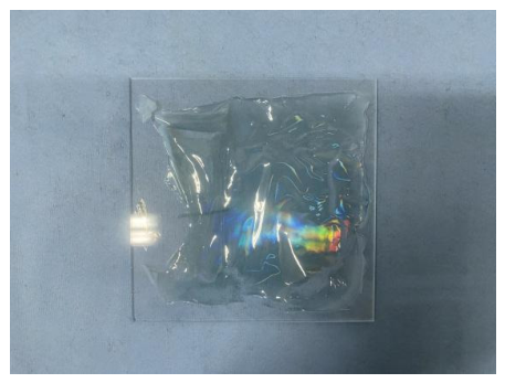
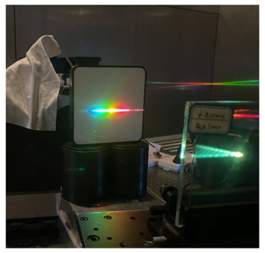
Using the proposed VPHG design method and the established grating fabrication process, short-wave infrared VPHGs for CO2 detection were successfully developed. Since infrared light is not directly visible, a broadband visible light source was used to illuminate the gratings to visually demonstrate their dispersion capability. The diffraction pattern of the fabricated VPHG, shown in Figure 23, displayed uniform dispersion and clear spectral separation.
Due to fabrication process variations, the parameters of the actual gratings deviated from their intended design values, necessitating precise measurement and characterization. Using the measured central wavelength at different positions, incidence angles, and the grating equation, the fringe spacing at various locations was calculated. Grating thickness at different points is measured with a thickness gauge, while refractive index modulation is derived from the measured grating parameters, diffraction efficiency data, and Kogelnik’s coupled-wave theory expression for TE wave diffraction efficiency. Table 8 presents these measured parameters for VPHGs fabricated using the optimized post-processing method. Slight deviations in the Bragg angle and grating period from the theoretical design were observed, attributed to errors in adjusting the exposure angles in the recording system. Excluding measurement uncertainties, both parameters exhibited good uniformity across the grating aperture. However, film thickness and refractive index modulation differed significantly from the theoretical design values. Although the post-processing method was optimized based on diffraction performance measurements, the process has not yet reached ideal conditions, resulting in discrepancies between actual and theoretical diffraction performance. Variations in thickness and refractive index modulation at different positions were attributed to non-uniform thickness of the unexposed plates and slight differences in development rates due to variations in the rinsing and dehydration procedures.
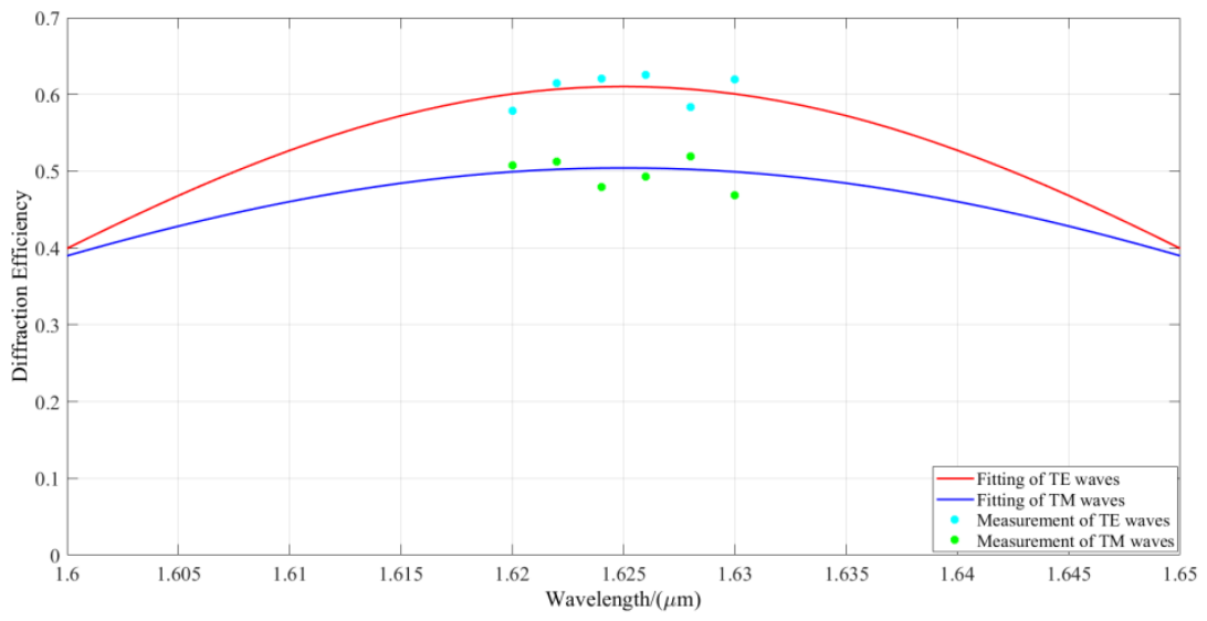
The measured diffraction efficiencies of the fabricated VPHG under TE polarization were 57.85%, 61.51%, 62.09%, 62.55%, 58.33%, and 61.94%, while under TM polarization they were 50.79%, 51.28%, 47.91%, 49.36%, 51.94%, and 46.83%. These values remained nearly unchanged over a period of seven days, indicating good temporal stability of the fabricated gratings. Using Kogelnik’s coupled-wave theory and the least squares method, the diffraction efficiency across different wavelengths was fitted. Figure 24 shows the fitting curve based on Equations (18) and (19) and the measured data. The fitted grating parameters were: period of 0.9390 μm, central wavelength of 1.625 μm, refractive index modulation of 0.04011, grating thickness of 23.8 μm, and a Bragg angle of 34.7007°. Compared to the theoretical design, the overall diffraction efficiency was lower, and the central wavelength shifted by approximately 10 nm toward shorter wavelengths. However, the spectral bandwidth exceeded 80 nm, and the maximum polarization sensitivity was close to 7%, both consistent with theoretical expectations. Analysis of the measurement and fitting results indicated that the primary source of deviation between measured and theoretical diffraction performance was the significant variation in grating thickness and refractive index modulation. Nonetheless, it should be possible to approach theoretical performance by further refining the post-processing technique to more precisely control film thickness and refractive index modulation during fabrication. Although this study thoroughly analyzed the influence of post-processing conditions and optimized the process, the method has not yet reached its full potential and still has room for further improvement.
This study also analyzed potential process improvements, which can be divided into two main areas: First, during theoretical design, the target spectral range should be pre-adjusted toward longer wavelengths to compensate for the observed central wavelength shift. Second, the optimal combination of rinsing and dehydration times must be further investigated during fabrication to achieve the desired refractive index modulation. Additionally, the film thickness variation under these conditions should be compensated by adjusting the target thickness during the dry plate coating stage, so that after swelling and shrinkage, the final grating film thickness more closely matches the theoretical design. Under these optimized conditions, it should be possible to produce high-performance VPHGs that fully meet application requirements. This integrated approach offers new directions for advancing VPHG fabrication technology.

7. Discussion

Currently, CO2 detection technology has advanced to the third generation of detection satellites. To meet the demands for large-scale real-time monitoring and high detection accuracy, spectral data acquisition payloads—specifically imaging spectrometers—are evolving toward higher signal-to-noise ratios, greater spectral resolution, and miniaturization, placing increasingly stringent requirements on their dispersive elements. VPHGs offer high diffraction efficiency, low scattering noise, uniform dispersion, and high spatial resolution. Using VPHGs in CO2 detection can enhance imaging spectrometer performance, improving detection precision and instrument capabilities. Therefore, this study conducts an in-depth investigation into high-performance VPHG design methods and the fabrication process of VPHGs.
To meet the demands for strong dispersion, high diffraction efficiency, and low polarization sensitivity, this study proposes a novel short-wave infrared VPHG design methodology based on inverse grating design principles. The method integrates a multi-objective simulated annealing algorithm with Kogelnik’s coupled-wave theory. A custom-developed optimization program was employed to construct a multi-objective fitness function combining application requirements and diffraction theory. Dynamic parameter tuning and intelligent variable perturbation strategies significantly improved the design efficiency and convergence of the optimization process. The design results demonstrated that under TE-polarized illumination, the grating achieved a spectral bandwidth of 122 nm with diffraction efficiency exceeding 95.35% across the target spectral range. Under TM polarization, the full width at half-maximum (FWHM) bandwidth was 54 nm with efficiency exceeding 82.21%, and polarization sensitivity was controlled within 6.97%, satisfying the stringent multidimensional performance requirements for CO2 detection. This method overcomes the performance limitations of traditional design approaches, improving computational efficiency and reducing design time by approximately 80% compared to conventional methods. It also successfully addresses the trade-offs among multiple diffraction parameters and is applicable to VPHG design in other spectral regions and applications. To meet the aperture and spectral range requirements of CO2 detection spectrometers, this study also developed a comprehensive 100 mm aperture VPHG fabrication process using DCG as the recording material. The process encompasses dry plate preparation, exposure, and post-processing steps, extending techniques originally developed for sub-50 mm devices. Aging procedures were improved by implementing a multi-stage thermal- and humidity-controlled aging protocol, enhancing material stability, film thickness uniformity, and initial hardness. An integrated exposure system capable of producing high-quality interference fields of up to 180 mm in diameter was successfully developed. A precision alignment method using a Hartmann wavefront sensor and theodolite was introduced, enabling accurate and portable optical alignment while supporting a multiplexed optical path. A real-time exposure monitoring system was also implemented to ensure optimal exposure control. By measuring diffraction efficiency and comparing various process conditions, improvements were made to development and fixation procedures, ensuring uniform diffraction performance across large apertures. Final VPHG samples were successfully fabricated. Although some discrepancies between measured and theoretical performance were observed, analysis indicates that more precise control of post-processing conditions could resolve these issues. The optimization strategy used in this study provides a solid foundation for fabricating large-format gratings. In conclusion, this study on VPHG design methods and fabrication processes lays a theoretical foundation for the development of medium-to-large aperture, short-wave infrared VPHGs and offers a practical solution for core components in atmospheric remote sensing spectrometers. It is explicitly clarified that the experimental validation of the fabricated gratings is restricted to the 1.620–1.630 μm wavelength range, and the full target design band of 1.620–1.650 μm has not been experimentally verified in this work.

Author Contributions

Writing—original draft preparation, S.W.; writing—review and editing, Y.Z.; methodology S.W. and L.D.; software, Z.J. and Y.F.; investigation, C.L.; validation, S.W.; data curation, S.W.; visualization, L.D.; resources, Y.Z.; project administration, C.L.; funding acquisition, Y.Z.; supervision, L.D. All authors have read and agreed to the published version of the manuscript.

Funding

This work was supported by the National Key Research and Development Program of China (2022YFB3904804), the National Natural Science Foundation of China (No. 62334010), and the Fund of State Key Laboratory of Applied Optics (E11662A2Q100).

Data Availability Statement

The data that support the findings of this study are available from the corresponding author upon reasonable request.

Conflicts of Interest

The authors declare no conflicts of interest.

References

  1. Gómez-Sanabria, A.; Kiesewetter, G.; Klimont, Z.; Schoepp, W.; Haberl, H. Potential for future reductions of global GHG and air pollutants from circular waste management systems. Nat. Commun. 2022, 13, 106. [Google Scholar] [CrossRef]
  2. Christiani, P.; Rana, P.; Räsänen, A.; Pitkänen, T.P.; Tolvanen, A. Detecting Spatial Patterns of Peatland Greenhouse Gas Sinks and Sources with Geospatial Environmental and Remote Sensing Data. Environ. Manag. 2024, 74, 461–478. [Google Scholar] [CrossRef] [PubMed]
  3. Löscher, A.; Bézy, J.-L.; Meijer, Y.; Sierk, B.; Caron, J. Carbonsat instrument pre- developments: Towards monitoring carbon dioxide and methane concentrations from space. In Proceedings of the International Conference on Space Optics—ICSO 2016; Karafolas, N., Cugny, B., Sodnik, Z., Eds.; SPIE: Biarritz, France, 2017; p. 222. [Google Scholar] [CrossRef]
  4. Singh, S.; Avtar, R.; Jain, A.; Alsulamy, S.; Ouda, M.M.; Kharrazi, A. Identifying Micro-Level Pollution Hotspots Using Sentinel-5P for the Spatial Analysis of Air Quality Degradation in the National Capital Region, India. Sustainability 2025, 17, 2241. [Google Scholar] [CrossRef]
  5. Ye, B.; Tian, S.; Cheng, Q.; Ge, Y. Application of Lithological Mapping Based on Advanced Hyperspectral Imager (AHSI) Imagery Onboard Gaofen-5 (GF-5) Satellite. Remote Sens. 2020, 12, 3990. [Google Scholar] [CrossRef]
  6. Imasu, R.; Matsunaga, T.; Nakajima, M.; Yoshida, Y.; Shiomi, K.; Morino, I.; Satitoh, N.; Niwa, Y.; Someya, Y.; Oishi, Y.; et al. Greenhouse gases Observing SATellite 2 (GOSAT-2): Mission overview. Prog. Earth Planet. Sci. 2023, 10, 33. [Google Scholar] [CrossRef]
  7. Zheng, J.; Zhang, H.; Zhang, S. Comparison of Atmospheric Carbon Dioxide Concentrations Based on GOSAT, OCO-2 Observations and Ground-Based TCCON Data. Remote Sens. 2023, 15, 5172. [Google Scholar] [CrossRef]
  8. Yang, Y.; Zhou, M.; Wang, W.; Ning, Z.; Zhang, F.; Wang, P. Quantification of CO2 Emissions from Three Power Plants in China Using OCO-3 Satellite Measurements. Adv. Atmos. Sci. 2024, 41, 2276–2288. [Google Scholar] [CrossRef]
  9. Foote, M.D.; Dennison, P.E.; Sullivan, P.R.; O’Neill, K.B.; Thorpe, A.K.; Thompson, D.R.; Cusworth, D.H.; Duren, R.; Joshi, S.C. Impact of scene-specific enhancement spectra on matched filter greenhouse gas retrievals from imaging spectroscopy. Remote Sens. Environ. 2021, 264, 112574. [Google Scholar] [CrossRef]
  10. Ebizuka, N.; Okamoto, T.; Hosobata, T.; Yamagata, Y.; Sasaki, M.; Uomoto, M.; Shimatsu, T.; Sato, S.; Hashimoto, N.; Tanaka, I.; et al. Novel Diffraction Gratings for Next Generation Spectrographs with High Spectral Dispersion; Navarro, R., Burge, J.H., Eds.; SPIE Astronomical Telescopes + Instrumentation; SPIE: Edinburgh, UK, 2016; p. 99122Z. [Google Scholar] [CrossRef]
  11. Ebizuka, N.; Morita, S.; Yamagata, Y.; Sasaki, M.; Bianco, A.; Tanabe, A.; Hashimoto, N.; Hirahara, Y.; Aoki, W. Birefringence Bragg Binary (3B) Grating, Quasi-Bragg Grating and Immersion Gratings; Navarro, R., Cunningham, C.R., Barto, A.A., Eds.; SPIE Astronomical Telescopes + Instrumentation; SPIE: Montréal, QC, Canada, 2014; p. 91515C. [Google Scholar] [CrossRef]
  12. Loukina, T.; Massenot, S.; Chevallier, R.; Heggarty, K.; Shigapova, N.M.; Skochilov, A.F. Volume diffraction gratings for optical telecommunications applications: Design study for a spectral equalizer. Opt. Eng. 2004, 43, 2658–2665. [Google Scholar] [CrossRef][Green Version]
  13. Wu, T.; Ma, J.; Wang, C.; Wang, H.; Su, P. Full-Color See-Through Three-Dimensional Display Method Based on Volume Holography. Sensors 2021, 21, 2698. [Google Scholar] [CrossRef]
  14. Yu, C.; Peng, Y.; Zhao, Q.; Li, H.; Liu, X. Highly efficient waveguide display with space-variant volume holographic gratings. Appl. Opt. 2017, 56, 9390–9397. [Google Scholar] [CrossRef] [PubMed]
  15. Lv, Z.; Liu, J.; Xu, L. A Multi-Plane Augmented Reality Head-Up Display System Based on Volume Holographic Optical Elements with Large Area. IEEE Photonics J. 2021, 13, 5200108. [Google Scholar] [CrossRef]
  16. Shishova, M.; Zherdev, A.; Odinokov, S.; Venediktov, V.; Lushnikov, D.; Kim, Y. Selective Couplers Based on Multiplexed Volume Holographic Gratings for Waveguide Displays. Photonics 2021, 8, 232. [Google Scholar] [CrossRef]
  17. Ding, Y.; Gu, Y.; Yang, Q.; Yang, Z.; Yang, Z.; Huang, Y.; Weng, Y.; Zhang, Y.; Wu, S. Breaking the in-coupling efficiency limit in waveguide-based AR displays with polarization volume gratings. Light Sci. Appl. 2024, 13, 185. [Google Scholar] [CrossRef] [PubMed]
  18. Gelsinger-Austin, P.J.; Luo, Y.; Watson, J.M.; Kostuk, R.K.; Barbastathis, G.; Barton, J.K.; Castro, J.M. Optical design for a spatial-spectral volume holographic imaging system. Opt. Eng. 2010, 49, 043001. [Google Scholar] [CrossRef]
  19. Robertson, J.G.; Taylor, K.; Baldry, I.K.; Gillingham, P.R.; Barden, S.C. ATLAS: A Cassegrain Spectrograph Based on Volume Phase Holographic Gratings; Iye, M., Moorwood, A.F.M., Eds.; Astronomical Telescopes and Instrumentation; SPIE: Munich, Germany, 2000; p. 194. [Google Scholar] [CrossRef]
  20. Ishikawa, Y.; Sirk, M.M.; Edelstein, J.; Jelinsky, P.; Brooks, D.; Tarle, G. Comprehensive Measurements of the Volume-phase Holographic Gratings for the Dark Energy Spectroscopic Instrument. Astrophys. J. 2018, 869, 24. [Google Scholar] [CrossRef]
  21. Sabel, T.; Lensen, M.C. Volume Holography: Novel Materials, Methods and Applications. In Holographic Materials and Optical Systems; Holographic Materials and Optical Systems; InTech: London, UK, 2017; ISBN 978-953-51-3037-6. [Google Scholar] [CrossRef]
  22. Mahamat, A.H.; Narducci, F.A.; Schwiegerling, J. Design and optimization of a volume-phase holographic grating for simultaneous use with red, green, and blue light using unpolarized light. Appl. Opt. 2016, 55, 1618–1624. [Google Scholar] [CrossRef]
  23. Arns, J.A. Performance Characteristics of Advanced Volume Phase Holographic Gratings for Operation in the Near Infrared; Navarro, R., Burge, J.H., Eds.; SPIE Astronomical Telescopes + Instrumentation; SPIE: Edinburgh, UK, 2016; p. 991232. [Google Scholar] [CrossRef]
  24. Blanche, P.A.; Gailly, P.; Habraken, S.; Lemaire, P.; Jamar, C. Volume phase holographic gratings: Large size and high diffraction efficiency. Opt. Eng. 2004, 43, 2603. [Google Scholar] [CrossRef]
  25. Blanche, P.-A.; Gailly, P.; Habraken, S.; Lemaire, P.; Jamar, C. Mosaiced and High Line Frequency VPH Gratings for Astronomy; Atad-Ettedgui, E., Dierickx, P., Eds.; SPIE Astronomical Telescopes + Instrumentation; SPIE: Glasgow, UK, 2004; p. 208. [Google Scholar] [CrossRef]
  26. Insausti, M.; Garzón, F.; Rasilla, J.L.; Blanche, P.-A.; Lemaire, P. Performances of NIR VPHGs at Cryogenic Temperatures; Atad-Ettedgui, E., Lemke, D., Eds.; SPIE Astronomical Telescopes + Instrumentation; SPIE: Marseille, France, 2008; p. 70184T. [Google Scholar] [CrossRef]
  27. Kubota, T. 48 Years with holography. Opt. Rev. 2014, 21, 883–892. [Google Scholar] [CrossRef]
  28. Barden, S.C.; Arns, J.A.; Colburn, W.S. Volume-Phase Holographic Gratings and Their Potential for Astronomical Applications; D’Odorico, S., Ed.; Astronomical Telescopes & Instrumentation; SPIE: Kona, HI, USA, 1998; pp. 866–876. [Google Scholar] [CrossRef]
  29. Guo, J.; Tu, Y.; Yang, L.; Wang, L.; Wang, B. Holographic waveguide display with a combined-grating in-coupler. Appl. Opt. 2016, 55, 9293–9298. [Google Scholar] [CrossRef]
  30. Kogelnik, H. Coupled Wave Theory for Thick Hologram Gratings. BELL Syst. Tech. J. 1969, 48, 2909–2947. [Google Scholar] [CrossRef]
  31. Moharam, M.G.; Gaylord, T.K. Rigorous coupled-wave analysis of planar-grating diffraction. J. Opt. Soc. Am. 1981, 71, 811. [Google Scholar] [CrossRef]
  32. Colomina-Martínez, J.; Bravo, J.C.; Sirvent-Verdú, J.J.; Moya-Aliaga, A.; Francés, J.; Neipp, C.; Beléndez, A. Numerical Estimation of Bending in Holographic Volume Gratings by Means of RCWA and Deep Learning. Appl. Sci. 2024, 14, 10356. [Google Scholar] [CrossRef]
  33. Antony, G.; Cody, D.; Mintova, S.; Naydenova, I. Theoretical and Experimental Investigation of Slanted Volume Transmission Gratings for Holographic Gas Sensing. IEEE Sens. J. 2025, 25, 6502–6510. [Google Scholar] [CrossRef]
  34. Hamza, M.F.; Yap, H.J.; Choudhury, I.A. Recent advances on the use of meta-heuristic optimization algorithms to optimize the type-2 fuzzy logic systems in intelligent control. Neural Comput. Appl. 2017, 28, 979–999. [Google Scholar] [CrossRef]
  35. Ansari, Z.N.; Daxini, S.D. A State-of-the-Art Review on Meta-heuristics Application in Remanufacturing. Arch. Comput. Methods Eng. 2022, 29, 427–470. [Google Scholar] [CrossRef]
  36. Suman, B.; Kumar, P. A survey of simulated annealing as a tool for single and multiobjective optimization. J. Oper. Res. Soc. 2006, 57, 1143–1160. [Google Scholar] [CrossRef]
  37. Amine, K. Multiobjective Simulated Annealing: Principles and Algorithm Variants. Adv. Oper. Res. 2019, 2019, 8134674. [Google Scholar] [CrossRef]
  38. Mel’nichenko, Y.B.; Gomza, Y.P.; Shilov, V.V.; Kuzilin, Y.E. Mechanism of Index Modulation in Developed Dichromated Gelatin Films. J. Photogr. Sci. 1991, 39, 133–138. [Google Scholar] [CrossRef]
  39. Rogers, B.; Mikulchyk, T.; Oubaha, M.; Cody, D.; Martin, S.; Naydenova, I. Improving the Holographic Recording Characteristics of a Water-Resistant Photosensitive Sol–Gel for Use in Volume Holographic Optical Elements. Photonics 2022, 9, 636. [Google Scholar] [CrossRef]
  40. Sabel, T.; De Vicente Lucas, G.; Lensen, M.C. Simultaneous formation of holographic surface relief gratings and volume phase gratings in photosensitive polymer. Mater. Res. Lett. 2019, 7, 405–411. [Google Scholar] [CrossRef]
  41. Narita, A.; Oshima, J.; Iso, Y.; Hasegawa, S.; Tomita, Y. Red-sensitive organic nanoparticle-polymer composite materials for volume holographic gratings with large refractive index modulation amplitudes. Opt. Mater. Express 2021, 11, 614. [Google Scholar] [CrossRef]
  42. Veniaminov, A.V.; Bandyuk, O.V.; Andreeva, O.V. Materials with diffusion amplification for optical-information recording and theirstudy by a holographic method. J. Opt. Technol. 2008, 75, 306–310. [Google Scholar] [CrossRef]
  43. Liang-wen, X.; Shihong, L.; Bi-xian, P. Mechanism of Hologram Formation in Dichromated Gelatin with X-Ray Photoelectron Spectroscopy. Appl. Opt. 1998, 37, 3678. [Google Scholar] [CrossRef] [PubMed]
  44. Shankoff, T.A. Phase Holograms in Dichromated Gelatin. Appl. Opt. 1968, 7, 2101. [Google Scholar] [CrossRef]
  45. Zhang, F.; Shen, H.; Sun, Y. Shack-Hartmann wavefront sensor based on a two-dimensional mixed aperture diffractive lens array. Opt. Express 2024, 32, 30724–30741. [Google Scholar] [CrossRef]
Figure 1. Structure of VPHGs.
Photonics 13 00501 g001
Figure 2. Schematic of the Bragg diffraction principle.
Photonics 13 00501 g002
Figure 3. Computational model based on Kogelnik’s coupled-wave theory.
Photonics 13 00501 g003
Figure 4. Optimization process of the multi-objective simulated annealing algorithm.
Photonics 13 00501 g004
Figure 5. Results of the diffraction performance analysis. (a) diffraction efficiency under TE and TM polarizations; (b) diffraction efficiency by angular; (c) polarization sensitivity by wavelength; (d) diffraction efficiency by wavelength.
Photonics 13 00501 g005
Figure 6. Analysis results of full width at half maximum bandwidth. (a) TE polarization and FWHM; (b) TM polarization and FWHM.
Photonics 13 00501 g006
Figure 7. Diffraction performance analysis of the grating designed using VirtualLab Fusion. (a) diffraction efficiency by TE and TM; (b) Angular selectivity at the central wavelength; (c) Polarization sensitivity by wavelength; (d) Diffraction efficiency by wavelength.
Photonics 13 00501 g007
Figure 8. Principle of grating formation in dichromated gelatin.
Photonics 13 00501 g008
Figure 9. Fabrication process of DCG-based VPHG.
Photonics 13 00501 g009
Figure 10. Substrate glass after cleaning.
Photonics 13 00501 g010
Figure 11. Prepared DCG dry plates.
Photonics 13 00501 g011
Figure 12. Transmission-type VPHG exposure system.
Photonics 13 00501 g012
Figure 13. Beam expander lens: (a) mechanical design of the lens mount; (b) lens assembly and adjustment results.
Photonics 13 00501 g013
Figure 14. Mechanical structure of the system.
Photonics 13 00501 g014
Figure 15. Alignment optical path assisted by Hartmann sensor.
Photonics 13 00501 g015
Figure 16. Fine adjustment process of the system wavefront.
Photonics 13 00501 g016
Figure 17. Wavefront measurement results of the exposure system.
Photonics 13 00501 g017
Figure 18. Results of the exposure angle adjustment.
Photonics 13 00501 g018
Figure 19. Final recorded exposure system.
Photonics 13 00501 g019
Figure 20. Monitoring process of optimal exposure dosage.
Photonics 13 00501 g020
Figure 21. Photo of diffraction efficiency measurement system.
Photonics 13 00501 g021
Figure 22. Film delamination caused by insufficient fixing time.
Photonics 13 00501 g022
Figure 23. Dispersion pattern of the fabricated VPHG in the visible light spectrum.
Photonics 13 00501 g023
Figure 24. Fitted diffraction efficiency of the fabricated VPHG.
Photonics 13 00501 g024
Table 1. Weights of diffraction performance constraint conditions.
Weightb1b2b3b4b5b6b7b8b9b10
Value0.050.10.050.10.050.10.30.050.10.1
Table 2. Optimized design results of the grating.
ParameterValue
Δn0.06
d32 μm
θB35.002°
Λ0.9376 μm
F0.6125
Table 3. Diffraction performance of gratings prepared with short washing and dehydration times.
WavelengthWash for 5 min and Dehydrate for 5 min: ηWash for 10 min and Dehydrate for 3 min: η
1.620 μm49.75%50.23%
1.622 μm52.65%49.55%
1.624 μm59.39%54.91%
1.626 μm55.54%55.94%
1.628 μm57.30%49.84%
1.630 μm45.81%46.61%
Table 4. Diffraction performance of gratings prepared with 10-min washing and 5-min dehydration times.
λPosition 1 Position 2Position 3Position 4Position 5AverageIncidentη
1.620 μm0.24640.24220.23710.23860.23460.239780.429055.89%
1.622 μm0.22850.22920.21810.21670.21340.221180.405654.53%
1.624 μm0.31800.32290.32980.32430.31310.321620.544759.04%
1.626 μm0.25540.26050.26110.25510.26020.258460.462555.58%
1.628 μm0.20520.20130.20290.19900.20770.203220.380153.46%
1.630 μm0.23780.24150.23590.23080.23020.235240.438353.67%
Note: The measured values represent light intensity.
Table 5. Diffraction performance of gratings prepared with 10-min washing and 7-min dehydration times.
λPosition 1 Position 2Position 3Position 4Position 5AverageIncidentη
1.620 μm0.24170.24770.25460.24930.24340.247340.427257.90%
1.622 μm0.23400.23770.24260.23820.23130.236760.407258.14%
1.624 μm0.30770.31120.31470.30910.30410.309360.540857.21%
1.626 μm0.26250.26930.26400.27080.25970.265260.462357.38%
1.628 μm0.21390.20880.21740.21930.21240.214360.382056.11%
1.630 μm0.24130.24930.24700.25510.24310.247280.439256.30%
Table 6. Diffraction performance of gratings prepared with 15-min washing and 5-min dehydration times.
λPosition 1 Position 2Position 3Position 4Position 5AverageIncidentη
1.620 μm0.24160.24580.25070.24450.23890.24430.422357.85%
1.622 μm0.24750.25340.25910.25480.24820.252410.410561.51%
1.624 μm0.33100.33750.34210.34130.32910.33620.541662.09%
1.626 μm0.27730.27910.28710.27800.27440.279180.446362.55%
1.628 μm0.22530.20180.22400.22290.21630.218060.373858.33%
1.630 μm0.27840.28920.28990.26780.26230.277520.448161.94%
Table 7. Diffraction performance of gratings prepared with 15-min washing and 7-min dehydration times.
λPosition 1 Position 2Position 3Position 4Position 5AverageIncidentη
1.620 μm0.24450.24800.25790.24980.23960.247960.426958.08%
1.622 μm0.25020.25240.25650.25160.24530.25120.417660.16%
1.624 μm0.31670.32590.32760.32350.31510.321760.544059.15%
1.626 μm0.24800.25720.26180.26860.25370.257860.445057.95%
1.628 μm0.22500.23060.22460.21980.21330.22300.378458.93%
1.630 μm0.25380.26250.25700.25120.24740.254380.4460357.03%
Table 8. Measurement results of parameters at different positions of the fabricated VPHG.
VPHG ParametersPosition 1Position 2Position 3Position 4Position 5
Incidence angle59.760.359.960.159.6
Bragg angle34.612534.852734.693034.773034.5721
Grating period0.94110.93540.93910.93730.9420
Film layer thickness2424232522
Refractive index modulation0.397720.397760.415050.381850.43391
Disclaimer/Publisher’s Note: The statements, opinions and data contained in all publications are solely those of the individual author(s) and contributor(s) and not of MDPI and/or the editor(s). MDPI and/or the editor(s) disclaim responsibility for any injury to people or property resulting from any ideas, methods, instructions or products referred to in the content.