Article

Color Image Encryption Based on Phase-Only Hologram Encoding Under Dynamic Constraint and Phase Retrieval Under Structured Light Illumination

1
College of Optical and Electronic Technology, China Jiliang University, Hangzhou 310018, China
2
School of Optoelectronic Science and Engineering, Soochow University, Suzhou 215006, China
3
School of Science, East China Jiaotong University, Nanchang 330013, China
*
Author to whom correspondence should be addressed.
Photonics 2026, 13(1), 66; https://doi.org/10.3390/photonics13010066
Submission received: 1 December 2025 / Revised: 3 January 2026 / Accepted: 7 January 2026 / Published: 11 January 2026

Abstract

This paper introduces a color image encryption technique based on phase-only hologram (POH) encoding with dynamic constraint and phase retrieval under structured light illumination (SLI). During encryption, the color plaintext is first encoded into a POH. This hologram is then transformed into an amplitude distribution through phase-amplitude conversion. Subsequently, using an iterative phase retrieval algorithm under structured light, the amplitude is encrypted into a visible ciphertext image, while a POM set is produced. The resulting ciphertext exhibits a visible image pattern, rather than noise-like appearance, providing ultrahigh imperceptibility. Moreover, the dynamic constraint in hologram encoding ensures balanced quality across color channels, leading to high-quality decrypted images with correct keys. The incorporation of a structured phase mask and the POM set expands the key space and boosts security. In decryption, the decryption structured light (DSL) illuminates the ciphertext and the neural network sequentially to generate a reconstructed amplitude. This amplitude is converted into a phase distribution via amplitude-phase conversion, which then acts as the POH for color holographic reconstruction, yielding the decrypted image. Numerical simulations demonstrate the method’s feasibility, high security, and strong robustness.

1. Introduction

Since the double random phase encoding (DPRE) was proposed [1], optical image encryption technology has rapidly developed and gradually attracted widespread attention from research in the field of information security. In recent years, a series of cutting-edge technologies, such as ghost imaging [2,3,4], metasurface [5,6,7], compressive sensing [8,9,10,11], digital holography [12,13], computer-generated holography [14,15,16], quantum cryptography [17,18,19], have been introduced into optical image encryption, which has notably quickened the progression of optical image encryption technology toward practical implementation. However, most of the existing optical image encryption methods mainly solve the problem of grayscale image encryption and protection. Compared with grayscale image, color image can show real color information; thus, it can better reflect the content and details of the image. Therefore, how to encrypt and protect the color image has become a current research hotspot in the field of optical image encryption.
To date, the research on optical color image encryption mainly focuses on the terms of DRPE [20,21], interference [22,23], computer-generated holography [24,25,26], digital holography [27,28,29,30], metasurface [31], single-pixel imaging [32], and diffractive imaging [33,34,35,36]. However, there are two core common drawbacks in all color image encryption methods mentioned above: (1) the ciphertexts of all methods mentioned above are noise-like, which attracts unnecessary attention and increases vulnerability to attacks; (2) the key space is limited due to insufficient types and quantities of security keys, resulting in a relatively low level of security. Consequently, there is a pressing need for a color image encryption approach that offers high security and high information concealment simultaneously.
This paper addresses these challenges by proposing a color image encryption scheme. The method encrypts a color plaintext into a visible ciphertext image through POH encoding under dynamic constraint and phase retrieval under SLI. Concurrently, it generates a POM set composed of multiple POMs. Different from the cipheretxt with noise-like distribution, ciphertext with visible image distribution shows an ultrahigh imperceptibility, leading to a high information concealment for color plaintext image. Moreover, the adopted POH encoding method is based on dynamic constraint, which can effectively address the issue of non-uniform reconstructed quality of different color channels in the traditional POH encoding method for color image, ensuring a high quality of color decrypted image during correct decryption. Crucially, the optical parameters of the structured light serve as supplementary keys, augmenting the degrees of freedom within the key space. Furthermore, all phase-only masks constituting the diffractive neural network are utilized as security keys during decryption. This multi-key architecture significantly expands the overall key space and enhances cryptographic security. Consequently, the proposed encryption scheme demonstrates superior performance, characterized by an expansive key space, high security, excellent information concealment, and high-quality decryption.

2. The Proposed Color Image Encryption Method

2.1. Encryption Process

The encryption framework of the proposed color image encryption method is depicted in Figure 1. To completely illustrate the proposed color image encryption process, the encryption process is divided into two parts: (1) POH encoding under dynamic constraint and (2) phase retrieval under SLI, where the first and second parts are respectively divided into the following first seven steps (S1–S7) and the following last six steps (S8–S13):
S1: Initial condition deployment
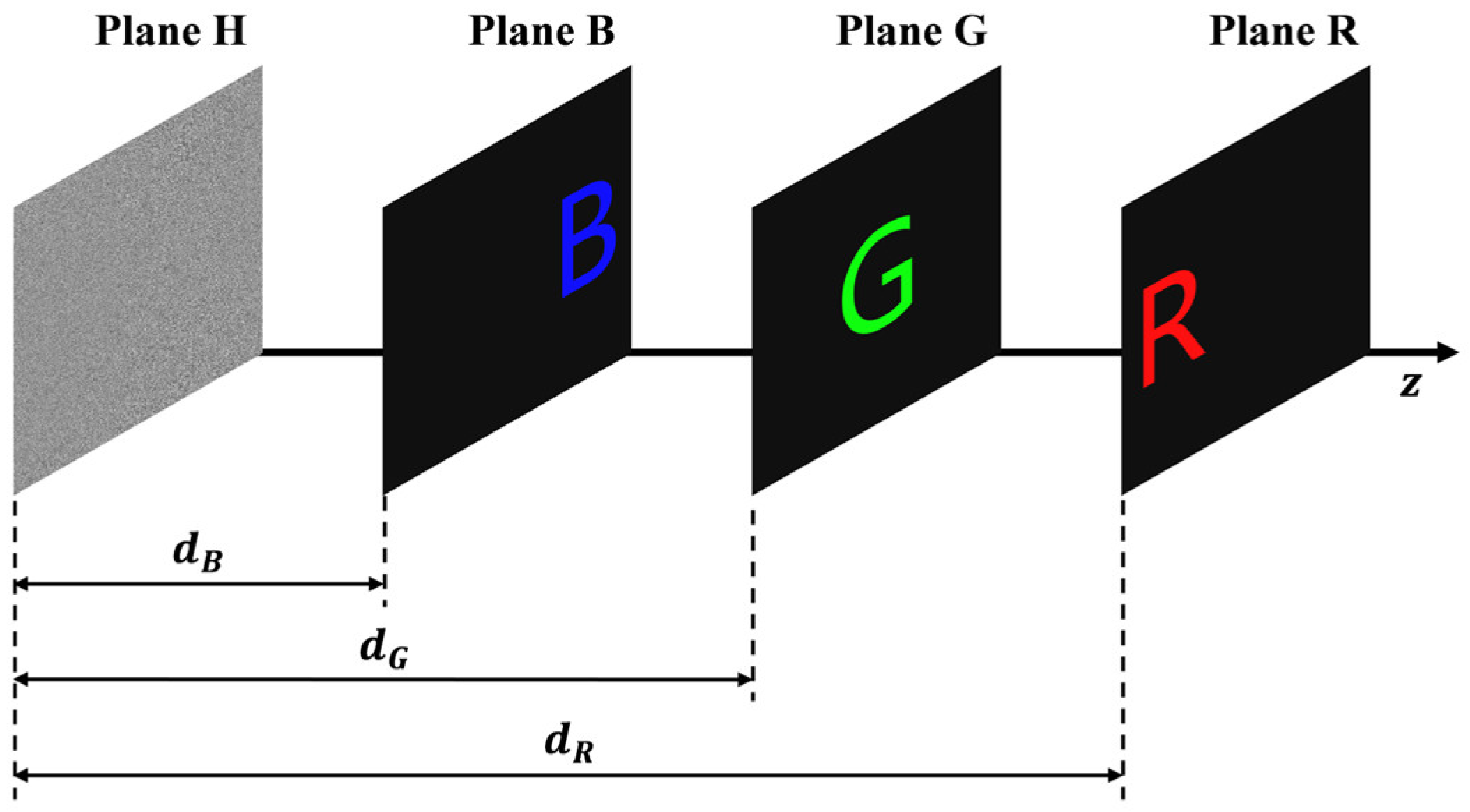
First, the wavelengths of red (R), green (G), and blue (B) color channels are set as λ R , λ G , and λ B , respectively. Afterwards, four planes parallel to each other are successively set along a straight line, which are respectively recorded as Plane H, Plane B, Plane G, and Plane R, as shown in Figure 2.
Moreover, the distances between Plane B, Plane G, Plane R, and Plane H are respectively recorded as d B , d G , d R , and d B ; d G and d R are characterized to meet the following proportional relationship:
d B : d G : d R = λ R : λ G : λ B
Thereafter, the color plaintext image to be encrypted is decomposed into R, G, and B components, whose amplitude distributions are respectively recorded as R component plaintext amplitude A R x R , y R , G component plaintext amplitude A G x G , y G , and B component plaintext amplitude A B x B , y B , which are respectively used for dynamic amplitude constraint of corresponding plane. Subsequently, the initial value of the number of dynamic constraints is set as 0. In addition, a complex amplitude U H x H , y H = e x p j φ r a n d x H , y H composed of a unit amplitude and a random phase distributed within the range of 0 , 2 π is set on Plane H, where φ r a n d x H , y H represents a phase randomly distributed within the range of 0 , 2 π . Afterwards, the encryption step S2 is run.
S2: Diffractive propagation under dynamic amplitude constraint of B component
A collimated plane light wave with a unit amplitude and the wavelength of λ R is employed as the encryption light wave, and it vertically incidents on Plane H. After the phase modulation of U H x H , y H , the encryption light wave U H x H , y H begins diffractive propagation forward until Plane B. Therefore, the complex amplitude of the encrypted light wave at Plane B, after forward propagation, is derived and can be expressed as:
U B x B , y B = A S D λ R , d B U H x H , y H = I F T F T U H x H , y H e x p j k d B 1 λ R f x B 2 λ R f y B 2
where A S D λ R , d B ( ) represents the operation of angular-spectrum diffraction with the wavelength of λ R and the distance of d B , F T ( ) and I F T ( ) respectively represent the operations of Fourier transform and inverse Fourier transform, j is the imaginary unit, k = 2 π / λ R is the wave number, and f x B and f y B denote the spatial frequency coordinates. In the subsequent step, the amplitude of the forward-propagating encryption light wave arriving at Plane B is extracted, preserved, and marked as the B plane reconstruction amplitude A B Δ x B , y B = U B x B , y B , where represents the operation of amplitude extraction. Thereafter, the correlation coefficient C C B between the B plane reconstruction amplitude A B Δ x B , y B and the B component plaintext amplitude A B x B , y B is calculated. Next, a dynamic amplitude constraint of B component is carried out to U B x B , y B , and then the complex amplitude U B x B , y B of the encryption light wave after the dynamic amplitude constraint of B component is obtained, which can be expressed as:
U B x B , y B = A C B ( i ) U B x B , y B = T B ( i ) U B x B , y B exp j arg U B x B , y B + 1 T B ( i ) A B x B , y B exp j arg U B x B , y B
where A C B ( i ) ( ) represents the operation of B component amplitude constraint under the i th time of dynamic constraint, arg ( ) represents the operation of phase extraction, and T B ( i ) stands for the B component amplitude constraint factor under the i th time of dynamic constraint, which can be mathematically expressed as:
T B ( i ) = 0 , i = 0 A B Δ x B , y B A B x B , y B , i = 1 T B ( i 1 ) + C C B C C a v g , i > 1
In fact, Equation (4) illustrates that the amplitude constraint factor varies with the number of iterations, aiming to ensure that the CCs of R/G/B three-color channels converge to the same preset threshold rapidly and uniformly. It is worth noting that each segment within Equation (4) is of great importance and irreplaceable, and the significance and necessity of each segment are summarized as follows: The first segment, corresponding to the 0-th time iteration, serves to provide a superior initial result, thereby avoiding the initiation of iterative search from completely random and erroneous values, which can shorten the convergence time for achieving the threshold. The second segment (for the 1st time iteration) and the third segment (for the iteration time greater than 1) are dedicated to balancing the CCs of R/G/B three-color channels. Their primary function is to ensure that the CCs of three-color channels converge to the same value, thereby minimizing color differences. In conclusion, each segment in the three-stage expression of Equation (4) is crucial and indispensable, and the synergistic effect of the three segments ensures R/G/B three-color channels rapidly converge to the same preset threshold, leading to a balanced color image with high quality.
Afterwards, the encryption light wave U B x B , y B begins diffractive propagation backward until Plane H; thus, the complex amplitude U B H x H , y H of the backward-propagating encryption light wave arriving at Plane H—after the dynamic amplitude constraint of B component—is obtained, which can be expressed as:
U B H x H , y H = I A S D λ R , d B U B x B , y B = A S D λ R , d B U B x B , y B
where I A S D λ R , d B represents the operation of inverse angular-spectrum diffraction with the wavelength of λ R and the distance of d B . Subsequently, a unit amplitude constraint is applied to U B H x H , y H , and then the output complex amplitude U B H x H , y H = U A C U B H x H , y H = exp j arg U B H x H , y H of the encryption light wave after the dynamic amplitude constraint of B component is obtained, where U A C represents the operation of unit amplitude constraint. Afterwards, the encryption step S3 is executed.
S3: Diffractive propagation under dynamic amplitude constraint of G component
The encryption light wave U B H x H , y H after the encryption step S2 starts diffractive propagation forward until Plane G; thus, the complex amplitude U G x G , y G = A S D λ R , d G U B H x H , y H of the forward-propagating encryption light wave arriving at Plane G is obtained. Subsequently, the amplitude of the encryption light wave propagating forward to Plane G is extracted and saved, and it is recorded as the G plane reconstruction amplitude A G Δ x G , y G = U G x G , y G . Afterwards, the correlation coefficient C C G between the G plane reconstruction amplitude A G Δ x G , y G and the G component plaintext amplitude A G x G , y G is calculated. Next, a dynamic amplitude constraint of G component is carried out to U G x G , y G , and then the complex amplitude U G x G , y G of the encryption light wav—after the dynamic amplitude constraint of G component—is obtained. Afterwards, the encryption light wave U G x G , y G begins diffractive propagation backward until Plane H; thus, the complex amplitude U G H x H , y H of the backward-propagating encryption light wave arriving at Plane H—after the dynamic amplitude constraint of G component—is obtained. Subsequently, a unit amplitude constraint is applied to U G H x H , y H , and then the output complex amplitude U G H x H , y H of the encryption light wave—after the dynamic amplitude constraint of G component—is obtained, which can be expressed as:
U G H x H , y H = U A C I A S D λ R , d G A C G ( i ) U G x G , y G
where A C G ( i ) ( ) represents the operation of G component amplitude constraint under the i th time of dynamic constraint. Afterwards, the encryption step S4 is run.
S4: Diffractive propagation under dynamic amplitude constraint of R component
The encryption light wave U G H x H , y H after the encryption step S3, starts diffractive propagation forward until Plane R; thus, the complex amplitude U R x R , y R = A S D λ R , d R U G H x H , y H of the forward-propagating encryption light wave arriving at Plane R is obtained. Subsequently, the amplitude of the forward-propagating encryption light wave arriving at Plane R is extracted and saved, and it is recorded as the R plane reconstruction amplitude A R Δ x R , y R = U R x R , y R . Afterwards, the correlation coefficient C C R between the R plane reconstruction amplitude A R Δ x R , y R and the R component plaintext amplitude A R x R , y R is calculated. Next, a dynamic amplitude constraint of R component is carried out to U R x R , y R , and then the complex amplitude U R x R , y R of the encryption light wave—after the dynamic amplitude constraint of R component—is obtained.
Afterwards, the encryption light wave U R x R , y R begins diffractive propagation backward until Plane H; thus, the complex amplitude U R H x H , y H of the backward-propagating encryption light wave arriving at Plane H—after the dynamic amplitude constraint of R component—is obtained. Subsequently, a unit amplitude constraint is applied to U R H x H , y H , and then the output complex amplitude U R H x H , y H of the encryption light wave—after the dynamic amplitude constraint of R component—is obtained, which can be expressed as:
U R H x H , y H = U A C I A S D λ R , d R A C R ( i ) U R x R , y R
where A C R ( i ) ( ) represents the operation of R component amplitude constraint under the i th time of dynamic constraint. Afterwards, the encryption step S5 is run.
S5: Judgment of phase output condition
The average value C C a v g of C C B , C C G , and C C R is calculated, and if C C a v g has exceeded the preset threshold q , that is, the phase output condition is met, then the encryption step S7 is executed. Conversely, if C C a v g has not exceeded the preset threshold q , that is, the phase output condition is not fulfilled, then the encryption step S6 is initiated instead.
S6: Phase update
U H x H , y H is updated as U R H x H , y H obtained in the encryption step S4, that is, U H x H , y H = U R H x H , y H ; simultaneously, the number of dynamic constraints is also updated from i to i + 1 , that is, i = i + 1 . Afterwards, the encryption step S2 is run.
S7: Output of POH and phase-to-amplitude conversion
An operation of phase extraction is performed to U R H x H , y H obtained in the encryption step S4; thus, the POH φ H x H , y H of the color plaintext image is generated and outputted, that is, φ H x H , y H = arg U R H x H , y H . Subsequently, an operation of phase-to-amplitude conversion is applied to φ H x H , y H ; thus, the converted amplitude A H x H , y H is obtained, which can be expressed as:
A H x H , y H = P A C φ H x H , y H
where P A C represents the operation of phase-to-amplitude conversion. Afterwards, the encryption step S8 is executed.
S8: Generation and illumination of encryption structured light (ESL)
A collimated plane wave of unit amplitude is phase-modulated by a composite encryption structured phase mask (ESPM) that integrates a Fresnel zone plate with a radial Hilbert mask, thereby generating the required ESL. Consequently, the complex amplitude distribution of the ESL is equivalent to the phase distribution E S P M ( ξ , η ) of the ESPM, whose mathematical expression can be written by:
E S P M ( ξ , η ) = exp j arg exp ( j π λ f r 2 ) + arg exp ( j P θ )
where λ is the wavelength of the ESL, f and r are respectively the focal length and radius of the Fresnel zone plate, and P and θ are respectively the topological charge number and spatial azimuth of the radial Hilbert mask. Subsequently, the ESL, generated after phase modulation by the ESPM, begins diffractive propagation forward until it reaches the preset visible ciphertext, and then the complex amplitude U 0 x 0 , y 0 = A S D λ , Z [ E S P M ( ξ , η ) ] of the ESL propagating forward to the front surface of the ciphertext is obtained, where Z is the distance from the ESPM to the ciphertext. Afterwards, the encryption step S9 is run.
S9: Unconstrained forward propagation
The ESL, after amplitude modulation by the ciphertext, continues diffractive propagation forward, sequentially passing through the planes of N POMs to be retrieved, until it reaches the reconstruction image plane. These N POMs to be retrieved are recorded as POM 1, POM 2, …, and POM N , respectively. The front surfaces of these POMs are respectively recorded as S f o r w a r d 1 , S f o r w a r d 2 , …, and S f o r w a r d N , and their back surfaces are respectively recorded as S b a c k w a r d 1 , S b a c k w a r d 2 , …, and S b a c k w a r d N . The complex amplitude U 1 ( x 1 , y 1 ) of the ESL propagating forward to S f o r w a r d 1 can be expressed as:
U 1 ( x 1 , y 1 ) = A S D λ , z 0 [ A S ( x 0 , y 0 ) U 0 ( x 0 , y 0 ) ]
where A S ( x 0 , y 0 ) is the amplitude of the preset visible ciphertext, and z 0 is the distance from the ciphertext to S f o r w a r d 1 . In the following stage, the ESL maintains diffractive propagation in the forward direction, sequentially reaching S f o r w a r d 2 , S f o r w a r d 3 , …, S f o r w a r d N , and S f o r w a r d N + 1 (the reconstruction image plane). The complex amplitude U n ( x n , y n ) of the ESL propagating forward to S f o r w a r d n can be expressed as:
U n ( x n , y n ) = A S D λ , z n 1 [ U n 1 ( x n 1 , y n 1 ) ] ( n = 2 : 1 : N + 1 )
where z n 1 is the distance from S f o r w a r d n 1 to S f o r w a r d n , and n = 2 : 1 : N + 1 stands for n changes from 2 to N + 1 with the step size of 1. Subsequently, the amplitude A n ( x n , y n ) and phase φ n ( x n , y n ) of the ESL propagating forward to S f o r w a r d n are extracted and saved, which can be respectively expressed as:
A n ( x n , y n ) = U n ( x n , y n ) φ n ( x n , y n ) = arg ( U n ( x n , y n ) ) ( n = 1 : 1 : N + 1 )
where n = 1 : 1 : N + 1 stands for n changes from 1 to N + 1 with the step size of 1. Afterwards, the encryption step S10 is executed.
S10: Judgment of convergence condition
After the amplitude A N + 1 ( x N + 1 , y N + 1 ) = U N + 1 ( x N + 1 , y N + 1 ) of the ESL propagating forward to the reconstruction image plane ( S f o r w a r d N + 1 ) is obtained, it is recorded as the reconstructed amplitude, and then the correlation coefficient C C between the reconstructed amplitude A N + 1 ( x N + 1 , y N + 1 ) and the converted amplitude A H ( x H , y H ) is calculated. If C C has exceeded the preset threshold σ , indicating that the convergence condition is met, then the encryption step S13 is executed. If C C has not exceeded the preset threshold σ , indicating that the convergence condition is not met, then the phase φ N + 1 ( x N + 1 , y N + 1 ) of the ESL propagating forward to the reconstruction image plane is kept unchanged and the converted amplitude A H ( x H , y H ) is used to replace the reconstructed amplitude A N + 1 ( x N + 1 , y N + 1 ) for realizing the amplitude constraint, thereby a new complex amplitude U K + 1 * x K + 1 , y K + 1 on the reconstruction image plane is generated, which is given by: U K + 1 * x K + 1 , y K + 1 = A H x H , y H exp j φ N + 1 ( x N + 1 , y N + 1 ) . Afterwards, the encryption step S11 is initiated.
S11: Backward propagation under phase constraint
The ESL, with the new complex amplitude U K + 1 * x K + 1 , y K + 1 on the reconstruction image plane, begins diffractive propagation backward, reaching the back surfaces ( S b a c k w a r d N , S b a c k w a r d N 1 , …… , S b a c k w a r d 1 ) of the N POMs in sequence. The complex amplitude U n ( x n , y n ) of the ESL propagating backward to S b a c k w a r d n can be expressed as:
U n ( x n , y n ) = I A S D λ , z n [ U n + 1 * ( x n + 1 , y n + 1 ) ] ( n = N : 1 : 1 )
where z n is the distance from S b a c k w a r d n to S b a c k w a r d n + 1 , and n = N : 1 : 1 stands for n changes from N to 1 with the step size of 1 . Subsequently, the amplitude A n ( x n , y n ) and phase φ n ( x n , y n ) of the ESL propagating backward to S b a c k w a r d n are extracted and saved, which can be respectively expressed as:
A n ( x n , y n ) = U n ( x n , y n ) φ n ( x n , y n ) = arg U n ( x n , y n ) ( n = N : 1 : 1 )
where n = N : 1 : 1 stands for n changes from N to 1 with the step size of 1 . Thereafter, the amplitude A n ( x n , y n ) of the ESL propagating backward to S b a c k w a r d n , which is saved in encryption step S11, is kept unchanged, and the phase φ n ( x n , y n ) of the ESL propagating forward to S f o r w a r d n saved in encryption step S9 is used to replace the phase φ n ( x n , y n ) of the ESL propagating backward to S b a c k w a r d n saved in encryption step S11 for realizing the phase constraint; thus, a new complex amplitude U n * ( x n , y n ) used for the next segment of backward propagation is generated, which can be expressed as:
U n * ( x n , y n ) = A n ( x n , y n ) exp j φ n ( x n , y n ) ( n = N : 1 : 1 )
where n = N : 1 : 1 stands for n changes from N to 1 with the step size of 1 . It is worth noting that Equations (13)–(15) should be circularly run along with the backward propagation of the ESL from S b a c k w a r d N to S b a c k w a r d 1 successively. Afterwards, the encryption step S12 is run.
S12: Forward propagation under phase constraint
The amplitude A 1 ( x 1 , y 1 ) of the ESL propagating forward to S f o r w a r d 1 , which is saved in encryption step S9, is kept unchanged, and the phase φ 1 ( x 1 , y 1 ) of the ESL propagating backward to S b a c k w a r d 1 saved in encryption step S11 is used to replace the phase φ 1 ( x 1 , y 1 ) of the ESL propagating forward to S f o r w a r d 1 saved in encryption step S9 for realizing the phase constraint; thus, a new complex amplitude U 1 ( x 1 , y 1 ) used for the next segment of forward propagation is generated, which can be written by: U 1 ( x 1 , y 1 ) = A 1 ( x 1 , y 1 ) exp j φ 1 ( x 1 , y 1 ) . Subsequently, the ESL begins diffractive propagation forward, reaching S f o r w a r d 2 , S f o r w a r d 3 , …, S f o r w a r d N , and S f o r w a r d N + 1 in sequence, where the complex amplitude U n ( x n , y n ) of the ESL propagating forward to S f o r w a r d n can be updated as:
U n ( x n , y n ) = A S D λ , z n 1 [ U n 1 ( x n 1 , y n 1 ) ] ( n = 2 : 1 : N + 1 )
where n = 2 : 1 : N + 1 stands for n changes from 2 to N + 1 with the step size of 1. Thereafter, the amplitude A n ( x n , y n ) and phase φ n ( x n , y n ) of the ESL propagating forward to S f o r w a r d n are extracted and saved again, which can be respectively expressed as:
A n ( x n , y n ) = U n ( x n , y n ) φ n ( x n , y n ) = arg U n ( x n , y n ) ( n = 2 : 1 : N + 1 )
where n = 2 : 1 : N + 1 stands for n changes from 2 to N + 1 with the step size of 1. Subsequently, the amplitude A n ( x n , y n ) of the ESL propagating forward to S f o r w a r d n , which is saved in encryption step S12, is kept unchanged, and the phase φ n ( x n , y n ) of the ESL propagating backward to S b a c k w a r d n saved in encryption step S11 is used to replace the phase φ n ( x n , y n ) of the ESL propagating forward to S f o r w a r d n saved in encryption step S12 for realizing the phase constraint; thus, a new complex amplitude U n ( x n , y n ) used for the next segment of forward propagation is generated, which can be expressed as:
U n ( x n , y n ) = A n ( x n , y n ) exp j φ n ( x n , y n ) ( n = 2 : 1 : N )
where n = 2 : 1 : N stands for n changes from 2 to N with the step size of 1. Likewise, it is noted that Equations (16)–(18) should be circularly run along with the forward propagation of the ESL from S f o r w a r d 2 to S f o r w a r d N + 1 successively. Afterwards, the encryption step S10 is run.
S13: Generation and output of POMs
On all planes where the POMs to be retrieved are located, the operation of phase subtraction is performed between the phase φ n ( x n , y n ) of the ESL propagating backward to S b a c k w a r d n saved in encryption step S11, and the phase φ n ( x n , y n ) of the ESL propagating forward to S f o r w a r d n saved in encryption step S12, thereby the phase distributions of all POMs to be retrieved are generated and outputted, where the phase distribution φ p n ( x n , y n ) of the POM n can be expressed as:
φ p n ( x n , y n ) = mod φ n ( x n , y n ) φ n ( x n , y n ) , 2 π ( n = 1 : 1 : N )
where mod ( ) represents the modulo operation, and n = 1 : 1 : N stands for n changes from 1 to N with the step size of 1.
So far, the encryption process has finished completely.

2.2. Decryption Process

The color image decryption process in accord with the encryption process described above is divided into the following three steps:
J1: Generation and illumination of DSL
Firstly, a collimated plane wave is first phase-modulated by a decryption structured phase mask (DSPM), thereby producing the DSL. This DSL then undergoes forward propagation to illuminate the preset ciphertext. The complex amplitude U 0 J x 0 , y 0 of the DSL propagating forward to the front surface of the ciphertext can be expressed as:
U 0 J x 0 , y 0 = A S D λ J , z 0 J D S P M ξ , η
where D S P M ξ , η represents the phase distribution of the DSPM, λ J represents the wavelength of the DSL, and d J is the distance from the DSPM to the ciphertext. Afterwards, the decryption step J2 is run.
J2: Forward diffractive decryption
The DSL, after the amplitude modulation by the ciphertext, continues diffractive propagation forward; thus, the complex amplitude U 1 J x 1 , y 1 of the DSL propagating forward to S f o r w a r d 1 can be expressed as:
U 1 J x 1 , y 1 = A S D λ J , z 0 J A S ( x 0 , y 0 ) U 0 J x 0 , y 0
where z 0 J represents the distance from the ciphertext to S f o r w a r d 1 during decryption. The DSL then propagates forward diffractively, reaching S f o r w a r d 2 , S f o r w a r d 3 , …, S f o r w a r d N , and S f o r w a r d N + 1 (the reconstructed image plane) in sequence. The complex amplitude U n J x n , y n of the DSL propagating forward to S f o r w a r d n can be expressed as:
U n J x n , y n = A S D λ J , z ( n 1 ) J U n 1 J x n 1 , y n 1 exp j φ p n 1 x n 1 , y n 1 n = 2 : 1 : N + 1
where z ( n 1 ) J represents the distance from S f o r w a r d n 1 to S f o r w a r d n during decryption, and n = 2 : 1 : N + 1 stands for n changes from 2 to N + 1 with the step size of 1. Afterwards, the amplitude A N + 1 J x N + 1 , y N + 1 of the DSL propagating forward to the reconstructed image plane ( S f o r w a r d N + 1 ) is extracted and saved, and it is recorded as the reconstructed amplitude, which is given by: A N + 1 J x N + 1 , y N + 1 = U N + 1 J x N + 1 , y N + 1 . Thereafter, an operation of amplitude-to-phase conversion is applied to A N + 1 J x N + 1 , y N + 1 ; thus, the converted phase φ H J x H , y H is obtained, which can be expressed as:
φ H J x H , y H = A P C A N + 1 J x N + 1 , y N + 1
where A P C represents the operation of amplitude-to-phase conversion. Afterwards, the decryption step J3 is run.
J3: Color holographic reconstruction decryption
The converted phase φ H J x H , y H is firstly placed on Plane H, and then three unit-amplitude collimated plane waves with the wavelengths of λ R , λ G , and λ B are employed as the trichromatic decryption waves and simultaneously incident on Plane H vertically. After the phase modulation by φ H J x H , y H , the trichromatic decryption waves begin diffractive propagation forward until they reach Plane R; thus, the complex amplitudes U R J x R , y R , U G J x R , y R , and U B J x R , y R of the trichromatic decryption waves propagating forward to Plane R are obtained, which can be respectively expressed as:
U R J x R , y R = I A S D λ R , d R exp j φ H J x H , y H U G J x R , y R = I A S D λ G , d R exp j φ H J x H , y H U B J x R , y R = I A S D λ B , d R exp j φ H J x H , y H
Subsequently, the amplitudes of the trichromatic decryption waves propagating forward to Plane R are extracted and saved, which are respectively recorded as the R component decrypted amplitude A R J x R , y R = U R J x R , y R , the G component decrypted amplitude A G J x R , y R = U G J x R , y R , and the B component decrypted amplitude A B J x R , y R = U B J x R , y R . Thereafter, the R component decrypted amplitude A R J x R , y R , the G component decrypted amplitude A G J x R , y R , and the B component decrypted amplitude A B J x R , y R are combined to form a color image, which is the final color decrypted image.
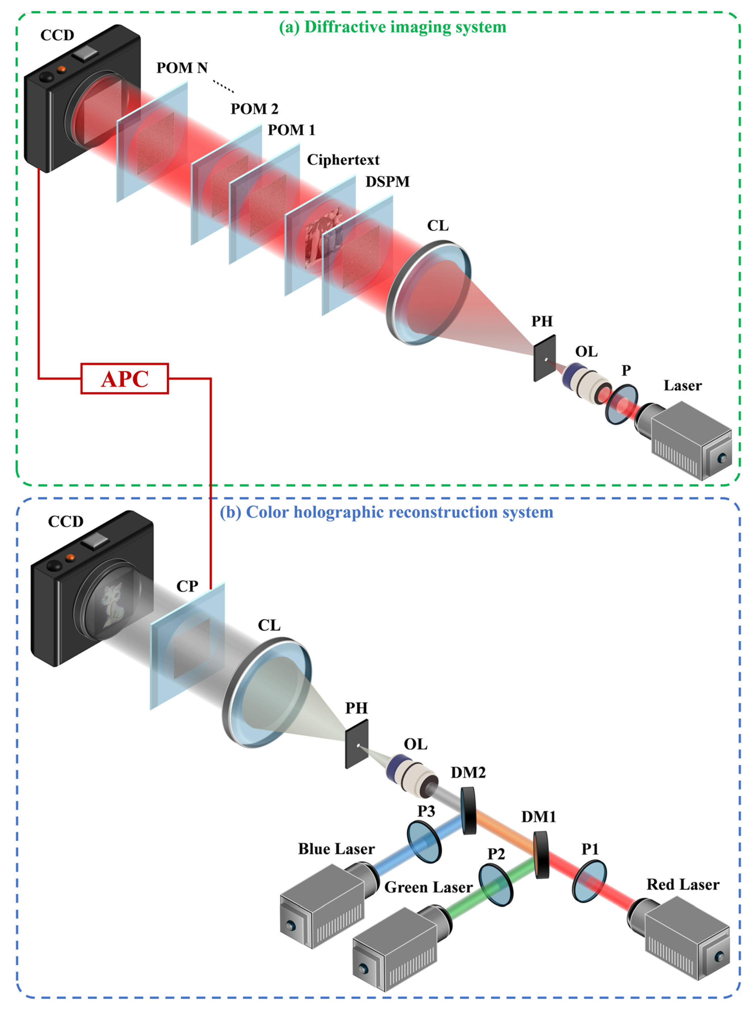
The decryption process is thus completed. It is noteworthy that this process can be implemented either entirely digitally or via a hybrid optical-digital approach. The latter primarily relies on two optical systems: a diffractive imaging system for steps J1–J2 and a color holographic reconstruction system for step J3, as illustrated in Figure 3a and Figure 3b, respectively.
The optical decryption process corresponding to Figure 3a is described as follows. First, light from a laser is sequentially conditioned by a polarizer, an objective lens, a pinhole, and a collimating lens to undergo polarization modulation, beam expansion, filtering, and collimation, thereby generating a plane wave. This wave is then phase-modulated by the DSPM to form the DSL. This DSL propagates forward to illuminate the preset ciphertext, which acts as an amplitude modulator. The amplitude-modulated light subsequently illuminates the POM set composed of multiple POMs. Thereafter, the light emerging from the final POM propagates to the CCD. In such a way, a grayscale image can be captured by the CCD, which is the reconstructed amplitude. So far, optical decryption process in the decryption steps J1–J2 has been finished, and then the reconstructed amplitude captured by the CCD will be uploaded into a computer. Thereafter, an operation of amplitude-to-phase conversion is applied to the reconstructed amplitude by using a computer program such that the converted phase can be obtained and used for the next decryption step J3.
The concrete optical decryption process in accord with Figure 3b can be described as follows: three light waves emitted from a red laser, a green laser, and a blue laser are successively polarization-modulated, color-combined, beam-expanded, filtered, and collimated for generating a multicolor plane wave by three polarizers, two dichroic mirrors, an objective lens, a pinhole, and a collimating lens, respectively. Thereafter, the multicolor plane wave is phase-modulated by the aforementioned converted phase that plays the role of POH. Afterwards, the phase-modulated multicolor light propagates forward until the preset CCD such that the color decrypted image can be formed and captured by the CCD. So far, optical decryption process in the decryption step J3 has been finished. The optical decryption process corresponding to the setup in Figure 3b is as follows. First, beams from red, green, and blue lasers are individually polarization-modulated by their respective polarizers. They are then color-combined using two dichroic mirrors, and the combined beam is subsequently expanded, filtered, and collimated to form a multicolor plane wave. This wave is phase-modulated by the aforementioned converted phase, which functions as a POH. The modulated multicolor light then propagates to the CCD, where the color decrypted image is formed and captured. This completes the optical decryption process for step J3.


3. Simulations and Results

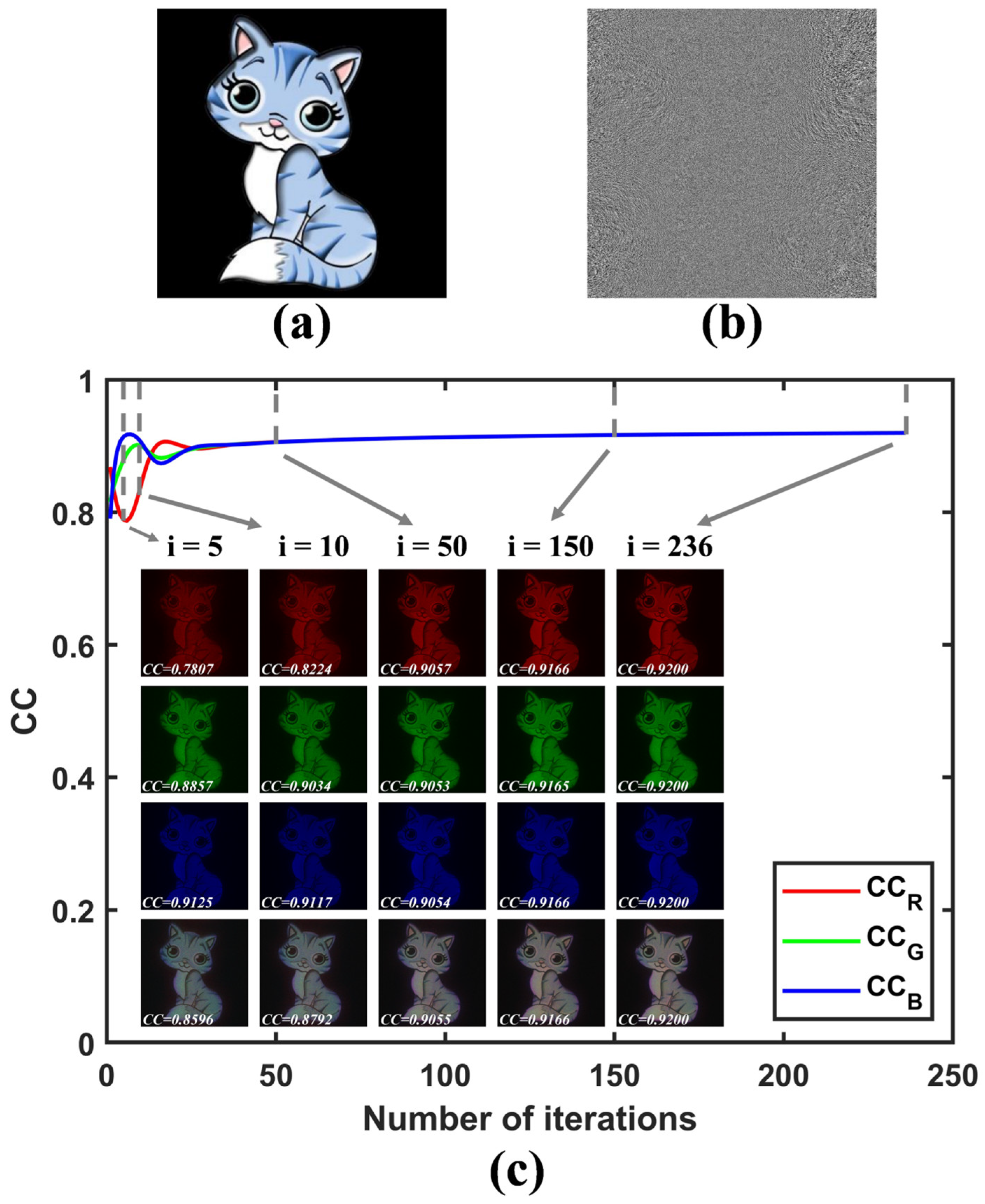
To validate the feasibility of the proposed color image encryption method, a series of numerical simulations are conducted using MATLAB R2022a. Initially, a color image (Cat) with the pixel number of 1024 × 1024 is selected as the original plaintext image for encryption, as shown in Figure 4a. Subsequently, the wavelengths of R, G, and B color channels are respectively set as λ R = 670   nm , λ G = 532   nm , and λ B = 473   nm , and the distances between Plane B, Plane G, Plane R, and Plane H are respectively set as d B = 70.6   mm , d G = 79 . 4   mm , and d R = 100   mm . Furthermore, the preset threshold q is set as 0.92. After the POH encoding process under dynamic constraint corresponding to the encryption steps S1–S7, the generated POH is depicted in Figure 4b. In fact, the POH encoding process under dynamic constraint is naturally an iterative calculation process, and the relationship curves between C C B , C C G , C C R , and the number of iterations are plotted in Figure 4c. From Figure 4c, it can be seen that although all three curves have a slight fluctuation in the beginning as the number of iterations gradually increase, three curves tend to converge after dozens of iterations, and the final converge values tend toward the same, which indicates that the quality levels for different color channels of holographic reconstructed images at this time are almost same. Furthermore, the average value C C a v g of C C B , C C G , and C C R has exceeded the preset threshold q   = 0 . 92 when the number of iterations reaches 236, that is, the phase output condition has been satisfied; thus, the POH shown in Figure 4b is generated.
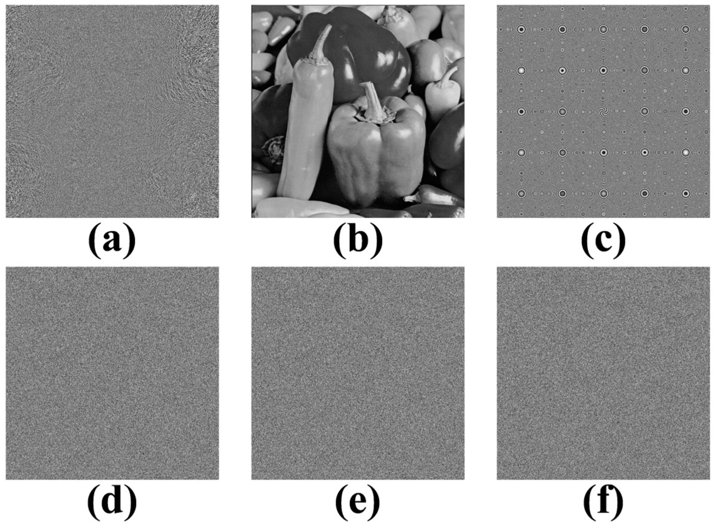
Thereafter, a phase-amplitude conversion operation is performed on the POH depicted in Figure 4b such that the converted amplitude is formed, which is shown in Figure 5a. Subsequently, a grayscale image (Peppers) with the pixel number of 1024 × 1024 is selected as the preset visible ciphertext image, which is displayed in Figure 5b. Furthermore, the diffraction neural network to be retrieved is set as a combination of three POMs (POM 1, POM 2, and POM 3); the wavelength λ of the ESL is set as 632 . 8 nm , the distance Z between the ESPM and the ciphertext is set as 40   mm ; the distance z 0 between the ciphertext and the POM 1 is set as 40   mm ; the distance z 1 between the POM 1 and the POM 2 is set as 150   mm ; the distance z 2 between the POM 2 and POM 3 is set as 100   mm ; the distance z 3 between the POM 3 and the reconstructed image plane is set as 150   mm ; the preset threshold σ is set as 0.9999; the ESPM is composed of the Fresnel zone plate with the focal length f of 20   mm ; and the radial Hilbert mask with the topological charge number P of 6, such that its phase distribution is shown in Figure 5c. After the phase retrieval process under SLI corresponding to the encryption steps S8–S13, three generated POMs (POM 1, POM 2, and POM 3) are shown in Figure 5d–f, respectively. So far, the encryption steps have been completely finished, the ciphertext is the preset visible image (Peppers), and the security keys include the digital keys and the phase keys, where the digital keys include the wavelength λ of the ESL, and the optical parameters of the ESPM (focal length f and topological charge number P ), as well as the diffraction distances Z , z 0 , z 1 , z 2 , z 3 ; the phase keys refer to the generated POMs (POM 1, POM 2, and POM 3), which are recorded as the first, second, and third phase keys.
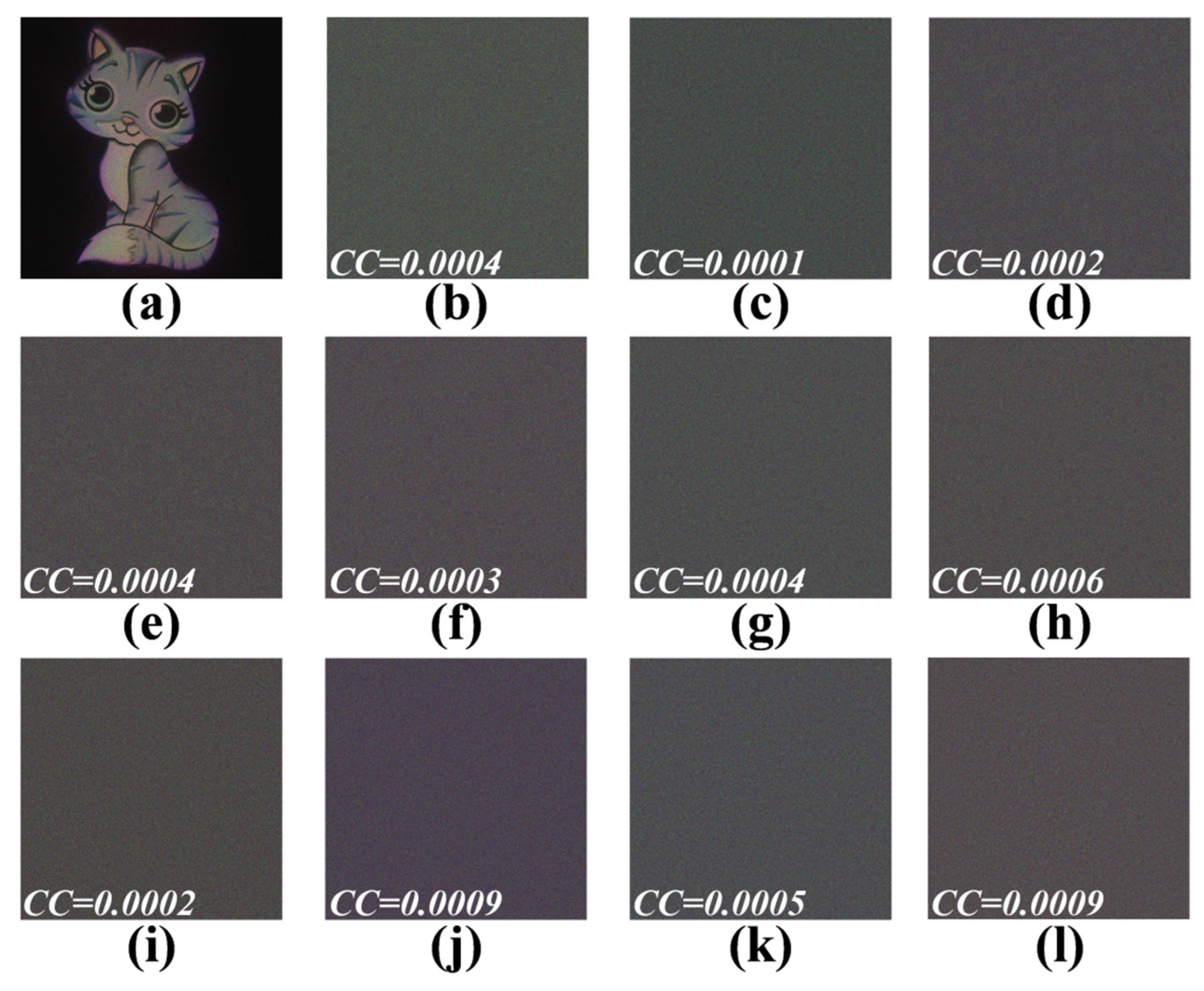
Next, the validity and security of these keys are tested. Figure 6a shows the color decrypted image when all decryption digital keys and phase keys are correct. Thereafter, the ciphertext is decrypted with only one wrong key. Figure 6b–l respectively shows the color decrypted images using a wrong digital key with wavelength deviation Δ λ of 1 nm , focal length deviation Δ f of 1 mm , topological charge number deviation Δ P of 1 , diffraction distance deviation Δ Z of 1 mm , diffraction distance deviation Δ z 0 of 1 mm , diffraction distance deviation Δ z 1 of 1 mm , diffraction distance deviation Δ z 2 of 1 mm , and diffraction distance deviation Δ z 3 of 1 mm , as well as wrong first phase key, wrong second phase key, and wrong third phase key, respectively. As shown in Figure 6, original color plaintext is reconstructed with high quality only when all digital and phase decryption keys are correct. However, a minor deviation in any single digital key or an error in any phase key leads to a complete decryption failure, producing results dominated by noise with no discernible features of original image. These results conclusively validate the security and validity of both digital and phase keys in the proposed method.
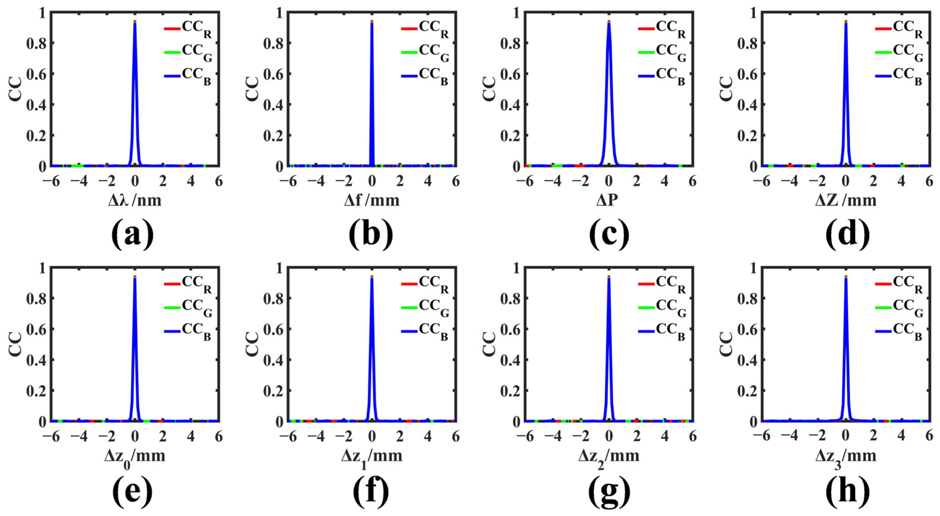
In addition, several relationship curves between the digital key deviations and the CCs calculated by three color components of color decrypted image and those of original color plaintext image are plotted to quantitatively describe the sensitivities of digital keys, where the CCs as functions of wavelength deviation Δ λ , focal length deviation Δ f , topological charge number deviation Δ P , distance deviation Δ Z , distance deviation Δ z 0 , distance deviation Δ z 1 , distance deviation Δ z 2 , and distance deviation Δ z 3 are shown in Figure 7a–h, respectively. As shown in Figure 7, a minute deviation in any digital key causes all CC values ( C C R , C C G , C C B ) to plummet to near zero, resulting in noise-like decrypted image from which no valid information can be discerned. This conclusively demonstrates the high sensitivities of digital keys in our proposed method.
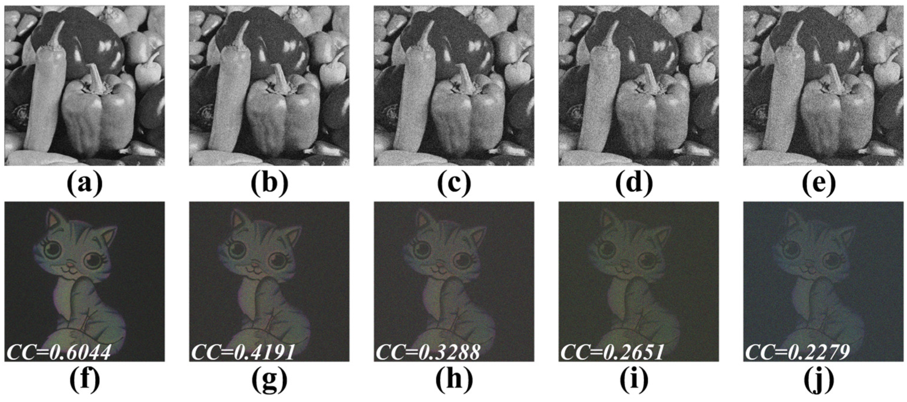
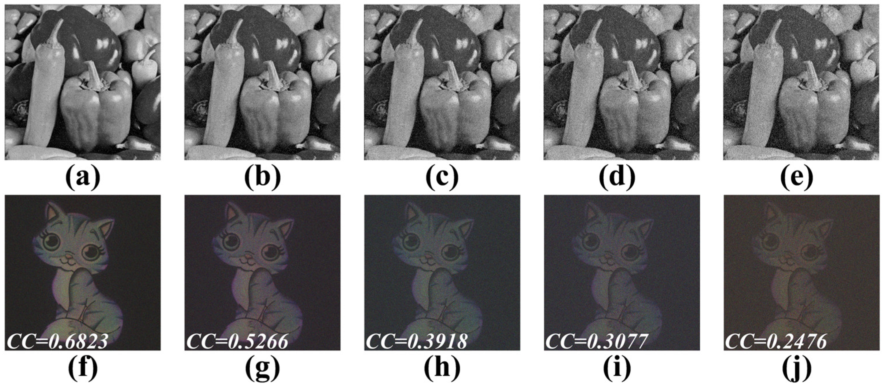
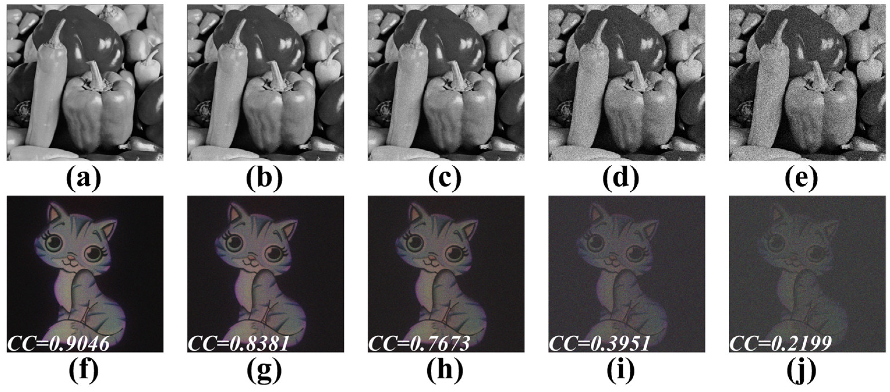
In addition, the robustness of the proposed method against noise and occlusion attacks is also evaluated. Figure 8a–e respectively shows the ciphertexts contaminated by Gaussian noises with the mean value of zero when the noise variance is from 0.02 to 0.10, and the noise-affected color decrypted images in accord with the contaminated ciphertexts shown in Figure 8a–e are depicted in Figure 8f–j, respectively. Figure 9a–e respectively shows the ciphertexts contaminated by salt-and-pepper noises when the noise density is from 0.04 to 0.20, and the noise-affected color decrypted images in accord with the contaminated ciphertexts shown in Figure 9a–e are depicted in Figure 9f–j, respectively. Figure 10a–e respectively shows the ciphertexts contaminated by Poisson noises when the scaling factor is 500, 100, 50, 10, and 5, and the noise-affected color decrypted images in accord with the contaminated ciphertexts shown in Figure 10a–e are depicted in Figure 10f–j, respectively. From the noise-affected color decrypted images shown in Figure 8, Figure 9 and Figure 10, it can be seen that the quality and CC value of color decrypted image gradually decrease as the noise variance increases; however, most useful information of original color plaintext image can be retained and easily recognized with the naked eye, regardless of Gaussian, salt-and-pepper, and Poisson noises, which proves that the proposed color image encryption method has good resistance to various common noise attacks, including Gaussian, salt-and-pepper, and Poisson noise attacks.
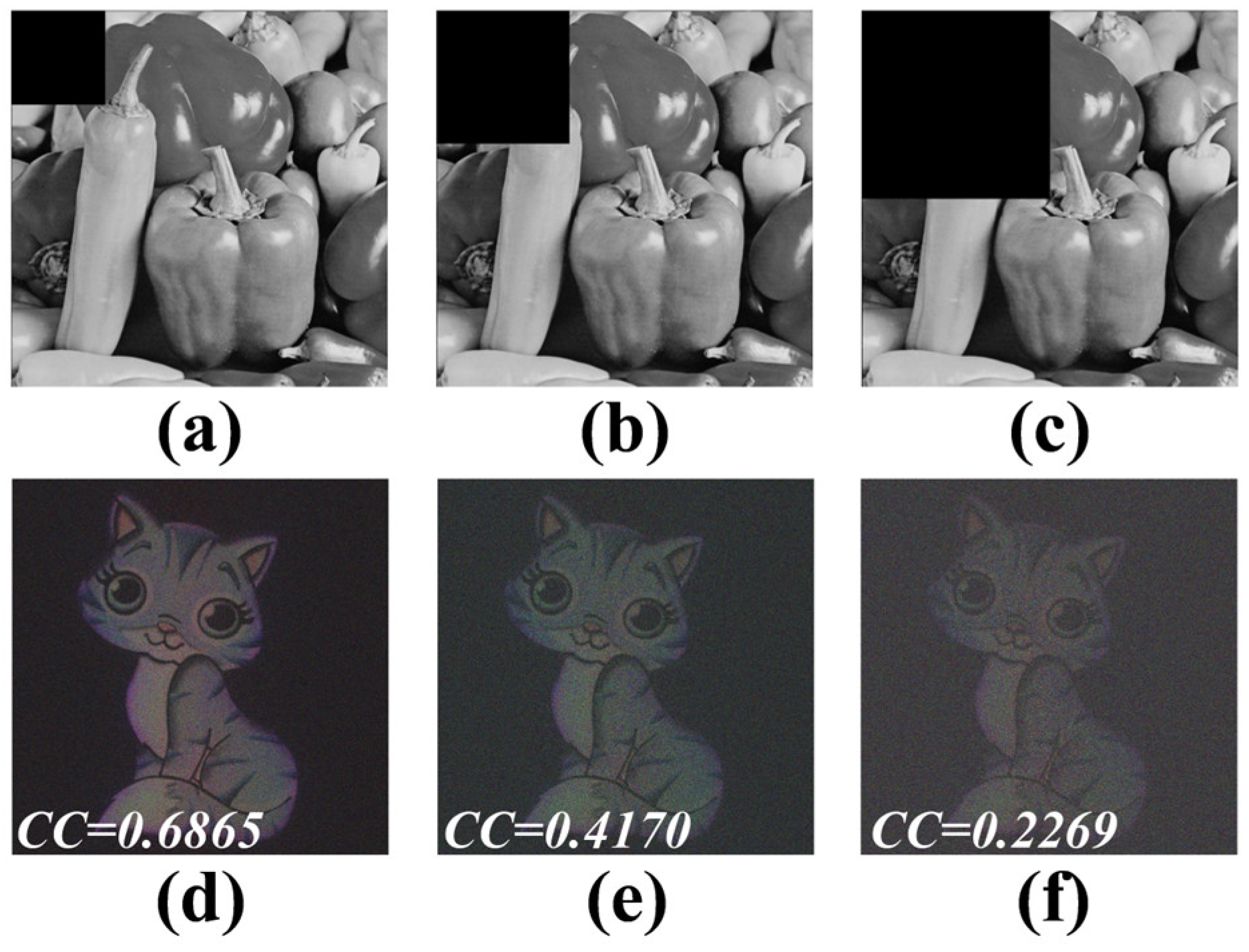
Next, in order to evaluate the resistance to occlusion attack, the ciphertext is partially cropped at different ratios. Figure 11a–c displays the ciphertexts with occlusion levels of 6.25%, 12.5%, and 25%, respectively. Their corresponding color decrypted images are shown in Figure 11d–f, respectively. From Figure 11, although the decryption quality degrades with increasing occlusion area, the majority of information from original plaintext remains visually discernible. This demonstrates the high robustness of the proposed method against occlusion attack.
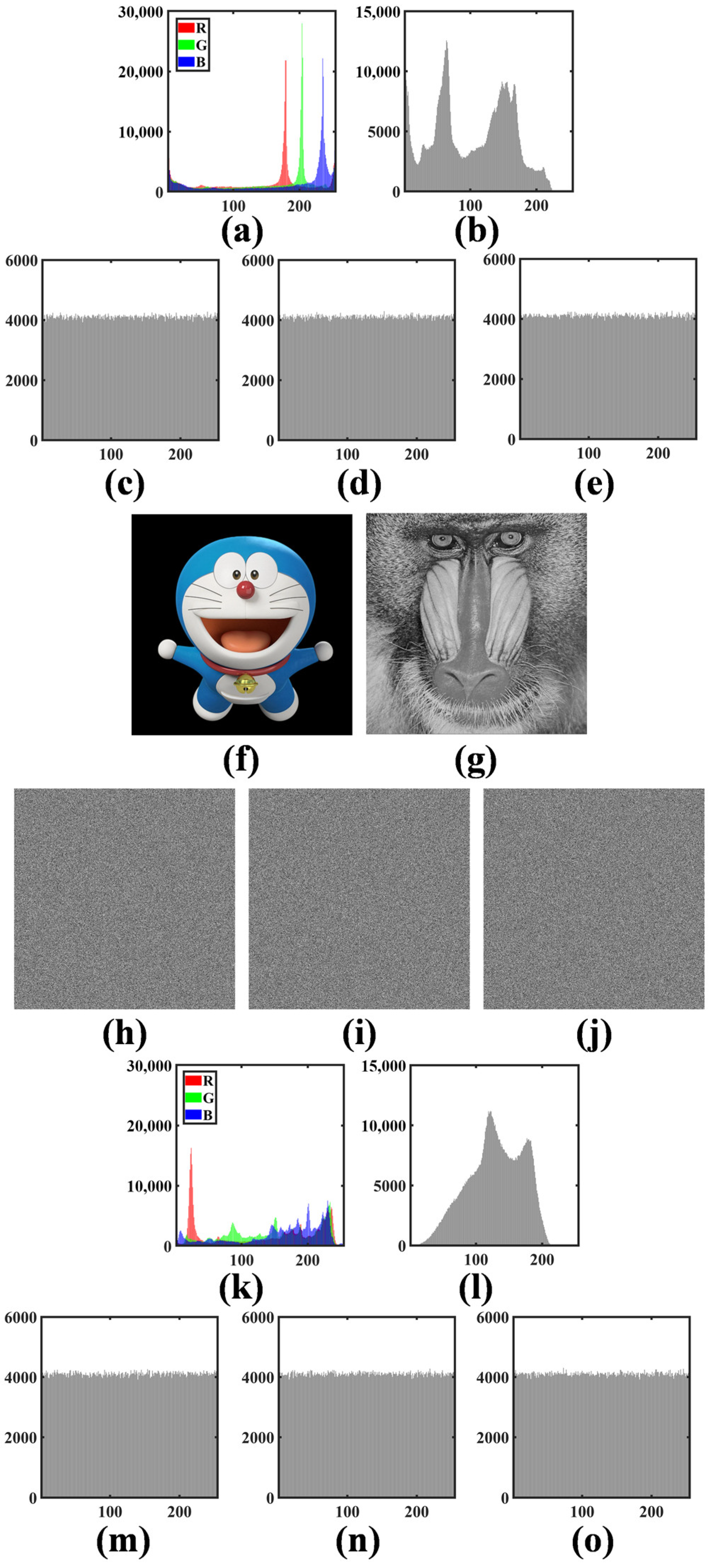
Moreover, the proposed method’s security against statistical attacks is further assessed via histogram analysis. Figure 12a–e respectively shows the histograms of the plaintext (Cat), the ciphertext (Peppers), and the retrieved POM 1, POM 2, and POM 3. As shown in Figure 12a–e, the histograms of the plaintext (Cat) and ciphertext (Peppers) differ markedly, while the retrieved POMs exhibit uniform randomness, which is strong evidence of effective encryption. Crucially, the non-uniform but structured histogram of the ciphertext confirms its visible-image nature, enhancing imperceptibility. Subsequently, the proposed method’s generality is also verified using a second image pair (Doraemon in Figure 12f and Baboon in Figure 12g). The corresponding retrieved POMs are shown in Figure 12h–j, and the histograms corresponding to Figure 12f–j are displayed in Figure 12k–o, respectively. It is obvious that plaintext/ciphertext histogram divergence and key randomness are reliably reproduced. Consequently, the proposed method demonstrates strong resilience against histogram attack.
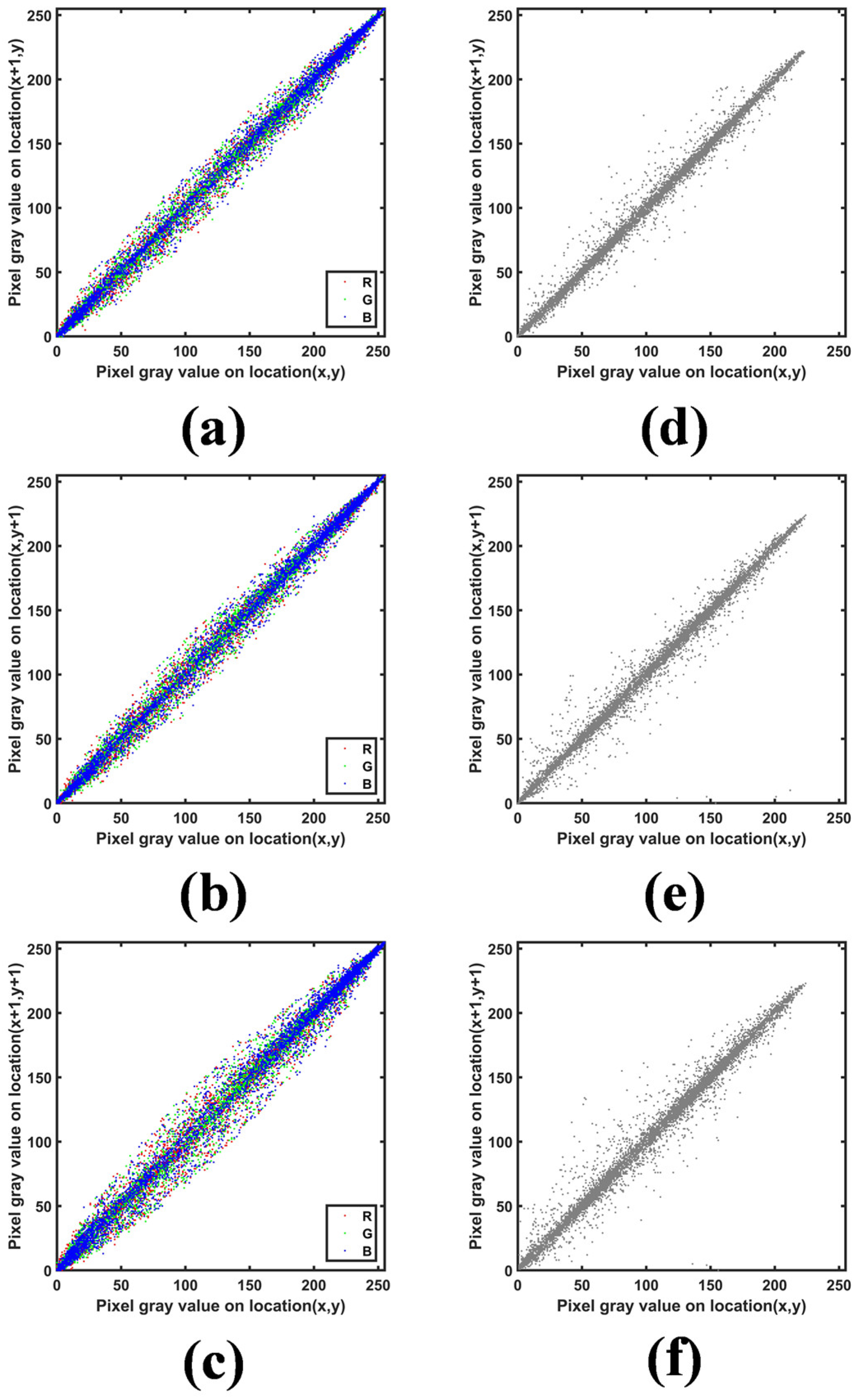
Furthermore, correlation analysis is performed by randomly selecting 10,000 pairs of adjacent pixels in horizontal, vertical, and diagonal directions from both plaintext (Cat) and ciphertext (Peppers). The correlation distributions for the plaintext are shown in Figure 13a–c, while those for the ciphertext are presented in Figure 13d–f. From Figure 13, it can be seen that the strong correlations inherent in the original image are preserved in the ciphertext across all directions. This retention of structural correlation demonstrates that the ciphertext maintains a visually meaningful image distribution, rather than a noise-like appearance. Consequently, the proposed method exhibits strong resistance against correlation analysis attacks, while simultaneously achieving high imperceptibility.
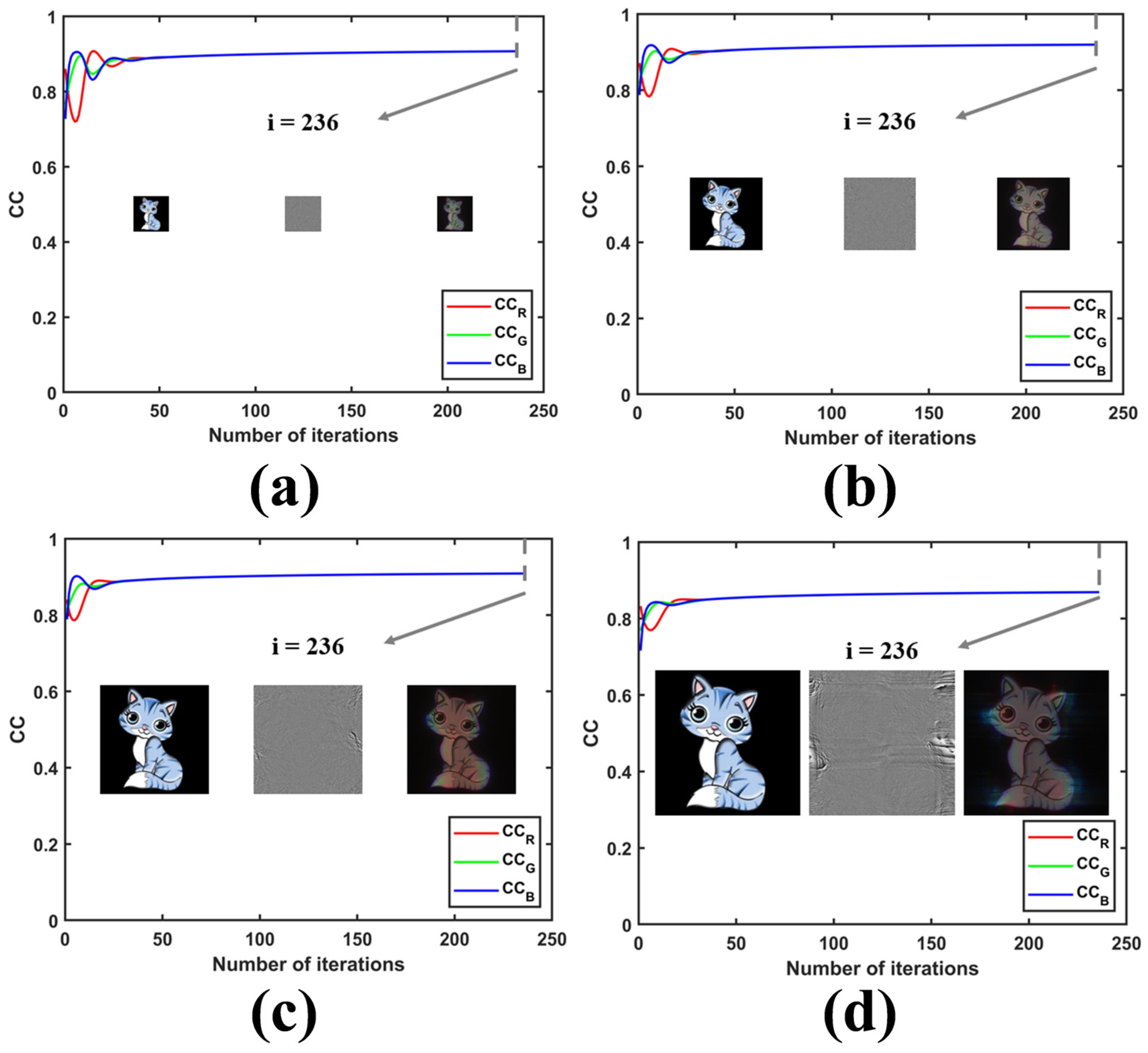
Next, in order to check the scalability of the proposed method to different resolutions, three groups of specific simulations were performed by using three additional image resolutions: 512 × 512, 1536 × 1536, 2048 × 2048. Concretely, the same color image (Cat) and grayscale image (Peppers) are resized to different resolutions, maintaining all other parameters consistent with the original simulation. Figure 14a–d respectively shows the relationship curves between C C B , C C G , C C R , and the number of iterations under the resolutions of 512 × 512, 1024 × 1024, 1536 × 1536, and 2048 × 2048, where color plaintext image and POH as well as color decrypted image under each resolution are displayed within Figure 14. From Figure 14, it can be seen that all three-channel curves finally converge to the same value no matter the resolution is 512 × 512, or 1024 × 1024, or 1536 × 1536, or 2048 × 2048; therefore, it is evident that the function of balancing the decrypted quality of different color channels brought by dynamic constraint is independent of the resolution of color plaintext image. In other words, the proposed method has an obvious effect of color-difference-suppression regardless of the resolution, which is beneficial for ensuring the high quality of color decrypted images. Consequently, it can be concluded that the proposed method has a certain scalability for different resolutions. However, it is also found from Figure 14 that although three curves at each resolution finally converge to the same value, ensuring a balance of three-color channels, the specific convergence values at different resolutions are not exactly the same. Especially, when the resolution reaches 2048 × 2048, the convergence value has already dropped below 0.9, which indicates that as the resolution increases, the convergence value, representing the decryption quality, has a slight degradation trend. Thus, if a high decryption quality needs to be maintained under a high resolution, substantial increment for the number of iterations may be necessary.
Finally, a comprehensive comparative analysis is conducted by selecting a color image encryption method [33] as a comparison method, whose implementation principle is similar with our proposed method, for the purpose of demonstrating the advantages of our proposed method intuitively. Table 1 shows the quantified comparison results between our proposed method and the method proposed in Ref. [33] in terms of security, concealment, robustness, and decryption quality. For the security aspect, a vital metric—key type and quantity—is compared, and the comparison results shown in Table 1 indicate that three phase keys as well as eight digital keys in our proposed method are far more than only two phase keys in the method proposed in Ref. [33], contributing to an apparent larger key space and higher level of security. For the concealment aspect, ciphertext image is always decisive. From Table 1, it can be seen that ciphertext in our proposed method is a visible image to avoid malicious attention, while that in the method proposed in Ref. [33] is a noise image that is easy to be observed and attracted attention by the attackers. This can also be seen from the correlations of ciphertext in three directions; they are close to one in our proposed method; however, they are close to zero in the method proposed in Ref. [33]. Therefore, it can be concluded that our proposed method expresses a higher concealment than the comparison method proposed in Ref. [33]. For the robustness aspect, this comparison is more intuitive because the occlusion tolerance in our proposed method and the method proposed in Ref. [33] are 25% and 6.5%, respectively. Consequently, it is clear that our proposed method has a stronger robustness than the method proposed in Ref. [33] for the aspects of occlusion attack. For the decryption quality aspect, all CCs ( C C B , C C G , and C C R ) of R/G/B three-color channels in our proposed method and the method proposed in Ref. [33] are counted in Table 1, and then several statistical indicators about C C B , C C G , and C C R , including mean value, range, variance, and coefficient of variation, are also calculated. Obviously, C C B , C C G , and C C R in our proposed method converge to the almost same value, while in the method proposed in Ref. [33] they converge to completely different three values. In addition, it can also be seen from the statistical indicators in Table 1 that the difference among CCs of R/G/B three-color channels in our proposed method is far less than that of the method proposed in Ref. [33], which indicates that R/G/B three-channel decrypted images in our proposed method are more balanced in decryption quality than that in the method proposed in Ref. [33]. In other words, our proposed method has less color difference and better decryption quality than the comparison method proposed in Ref. [33]. In summary, for the aspects of security, concealment, occlusion robustness, and decryption quality, the proposed method outperforms the method in Ref. [33] by virtue of a larger key space, a visually benign ciphertext image with higher correlations, superior occlusion tolerance, and more balanced color-channel decryption consistency with smaller inter-channel CC differences.

4. Discussion and Conclusions

This paper proposes a highly secure and imperceptible color image encryption method based on dynamic-constrained POH encoding and SLI-based phase retrieval. The encryption process first encodes a color plaintext into a POH under dynamic constraint. This POH is then converted into an amplitude distribution, which is finally encrypted into a visible ciphertext image via a phase retrieval algorithm under SLI. Concurrently, a POM set composed of multiple POMs is generated. Notably, the SLI introduces its optical parameters as supplementary keys, expanding the key space. Moreover, all POMs in the POM set also serve as decryption keys, collectively contributing to a larger key space and enhanced security. Furthermore, the final cipheretext possesses a visible image distribution, rather than a noise-like distribution, thereby showing an ultrahigh imperceptibility and leading to a high information concealment for color plaintext image. Moreover, the adopted POH encoding method is based on dynamic constraint, overcoming the problem about non-uniform reconstructed quality of different color channels in the traditional POH encoding method for color image, ensuring a high quality of color decrypted image during correct decryption. In the decryption process of the proposed method, the DSL successively illuminates the ciphertext and POM set for generating the reconstructed amplitude, and then the reconstructed amplitude is converted into a conversion phase through amplitude-phase conversion, and finally the conversion phase is served as the POH, generating the color decrypted image through color holographic reconstruction. To validate the proposed method, comprehensive computational simulations are conducted. The results confirm that high-quality decryption is achieved with correct keys. Moreover, the security of all keys and the high sensitivity of digital keys are also successfully verified, demonstrating the proposed method’s large key space and high security level. Furthermore, the proposed method exhibits strong robustness against various attacks, including Gaussian, salt-and-pepper, and Poisson noises, occlusion, histogram, and correlation analysis. In addition, the scalability of the proposed method to different resolutions is also demonstrated. Finally, a comprehensive comparative analysis is conducted by comparing our proposed method with the method proposed in Ref. [33], and it can be concluded that our proposed method shows the significant advantages in terms of security, concealment, occlusion robustness, and decryption quality.
Future work will focus on several promising directions to further enhance the system. First, the adopted structured light can be upgraded to a more complex type integrated with additional optical degrees of freedom (such as spatial frequency modulation, polarization modulation, and angular modulation) to further expand the key space of the encryption system. Moreover, the dimensionality of the retrieved POM set can be further increased by adding more independent POMs or introducing metasurface-based POMs with nanoscale sensitive parameters, which will enhance the encryption security. In addition, chaotic systems (e.g., Lorenz, Chen, or logistic maps) can be embedded into the existing encryption framework, where the initial conditions and control parameters of chaotic systems serve as additional keys to significantly expand the key space. Furthermore, other advanced image encryption technologies like compressive sensing or quantum walks can be combined with the proposed framework to further improve the security level. Finally, the scheme may be extended to a multiple-image encryption paradigm to broaden its application scope.

Author Contributions

Conceptualization, W.Z.; methodology, W.Z., Y.S. and Y.W.; software, W.Z.; validation, X.P.; formal analysis, C.L.; investigation, W.Z. and S.N.; resources, Y.S.; data curation, Y.S. and Z.C.; writing—original draft preparation, W.Z.; writing—review and editing, Y.S. and W.W.; supervision, Y.S.; project administration, Y.S. and W.W.; funding acquisition, Y.S. and W.W. All authors have read and agreed to the published version of the manuscript.

Funding

This research was funded by the Natural Science Foundation of Zhejiang Province, grant number LQ22F050005, ZCLZ25F0502, and Fundamental Research Funds for the Provincial Universities of Zhejiang, grant number 2022YW53, and National Natural Science Foundation of China (NSFC), grant number 62265006, and Program of Science and Technology Department of Jiangxi Province, grant number 20212BCJL23050, 20232BAB212017.

Institutional Review Board Statement

Not applicable.

Informed Consent Statement

Not applicable.

Data Availability Statement

Data underlying the results presented in this paper are not publicly available at this time but may be obtained from the authors upon reasonable request.

Conflicts of Interest

The authors declare no conflicts of interest.

References

  1. Refregier, P.; Javidi, B. Optical image encryption based on input plane and Fourier plane random encoding. Opt. Lett. 1995, 20, 767–769. [Google Scholar] [CrossRef] [Scilit]
  2. Sui, L.; Pang, Z.; Cheng, Y.; Cheng, Y.; Xiao, Z.; Tian, A.; Qian, K.; Asundi, A. An optical image encryption based on computational ghost imaging with sparse reconstruction. Opt. Lasers Eng. 2021, 143, 106627. [Google Scholar] [CrossRef] [Scilit]
  3. Guan, Q.; Deng, H.; Liang, W.; Zhong, X.; Ma, M. Multi-images encryption and watermarking with small number of keys via computational ghost imaging. Opt. Laser Technol. 2024, 168, 109957. [Google Scholar] [CrossRef] [Scilit]
  4. Huang, H.; Han, Z. Computational ghost imaging encryption using RSA algorithm and discrete wavelet transform. Results Phys. 2024, 56, 107282. [Google Scholar] [CrossRef] [Scilit]
  5. Qu, G.; Yang, W.; Song, Q.; Liu, Y.; Qiu, C.-W.; Han, J.; Tsai, D.-P.; Xiao, S. Reprogrammable meta-hologram for optical encryption. Nat. Commun. 2020, 11, 5484. [Google Scholar] [CrossRef] [Scilit] [PubMed]
  6. Zheng, P.; Dai, Q.; Li, Z.; Ye, Z.; Xiong, J.; Liu, H.-C.; Zheng, G.; Zhang, S. Metasurface-based key for computational imaging encryption. Sci. Adv. 2021, 7, eabg0363. [Google Scholar] [CrossRef] [Scilit] [PubMed]
  7. Yang, H.; Ou, K.; Wan, H.; Hu, Y.; Wei, Z.; Jia, H.; Cheng, X.; Liu, N.; Duan, H. Metasurface-empowered optical cryptography. Mater. Today 2023, 67, 424–445. [Google Scholar] [CrossRef] [Scilit]
  8. Gong, L.; Qiu, K.; Deng, C.; Zhou, N. An optical image compression and encryption scheme based on compressive sensing and RSA algorithm. Opt. Lasers Eng. 2019, 121, 169–180. [Google Scholar] [CrossRef] [Scilit]
  9. Brahim, A.H.; Pacha, A.A.; Said, N.H. Image encryption based on compressive sensing and chaos systems. Opt. Lasers Eng. 2020, 134, 106178. [Google Scholar]
  10. Xu, Q.; Sun, K.; He, S.; Zhu, C. An effective image encryption algorithm based on compressive sensing and 2D-SLIM. IEEE Trans. Ind. Inform. 2018, 14, 673–678. [Google Scholar] [CrossRef] [Scilit]
  11. Abuturab, M.R.; Alfalou, A. Multiple color image fusion, compression, and encryption using compressive sensing, chaotic-biometric keys, and optical fractional Fourier transform. Opt. Laser Technol. 2022, 151, 108071. [Google Scholar] [CrossRef] [Scilit]
  12. Javidi, B.; Nomura, T. Securing information by use of digital holography. Opt. Lett. 2000, 25, 28–30. [Google Scholar] [CrossRef] [Scilit]
  13. Shiu, M.-T.; Chew, Y.-K.; Chan, H.-T.; Wong, X.-Y.; Chang, C.-C. Three-dimensional information encryption and anticounterfeiting using digital holography. Appl. Opt. 2015, 54, A84–A88. [Google Scholar] [CrossRef] [Scilit] [PubMed]
  14. Kong, D.; Cao, L.; Shen, X.; Zhang, H.; Jin, G. Image encryption based on interleaved computer-generated holograms. IEEE Trans. Ind. Inform. 2018, 14, 673–678. [Google Scholar] [CrossRef] [Scilit]
  15. Xi, S.; Yu, N.; Wang, X.; Wang, X.; Lang, L.; Wang, H.; Liu, W.; Zhai, H. Optical encryption scheme for multiple-image based on spatially angular multiplexing and computer generated hologram. Opt. Lasers Eng. 2020, 127, 105953. [Google Scholar] [CrossRef] [Scilit]
  16. Wang, W.; Wang, X.; Xu, B.; Chen, J. Optical image encryption and authentication using phase-only computer-generated hologram. Opt. Lasers Eng. 2021, 146, 106722. [Google Scholar] [CrossRef] [Scilit]
  17. Pirandola, S.; Andersen, U.L.; Banchi, L.; Berta, M.; Bunandar, D.; Colbeck, R.; Englund, D.; Gehring, T.; Lupo, C.; Ottaviani, C.; et al. Advances in quantum cryptography. Adv. Opt. Photon. 2020, 12, 1012–1236. [Google Scholar] [CrossRef] [Scilit]
  18. Abd-El-Atty, B.; Iliyasu, A.M.; Alanezi, A.; El-latif, A.A.A. Optical image encryption based on quantum walks. Opt. Lasers Eng. 2021, 138, 106403. [Google Scholar] [CrossRef] [Scilit]
  19. Ma, Y.; Li, N.; Zhang, W.; Wang, S.; Ma, H. Image encryption scheme based on alternate quantum walks and discrete cosine transform. Opt. Express 2021, 29, 28338–28351. [Google Scholar] [CrossRef] [Scilit]
  20. Faragallah, O.S.; Alzain, M.A.; El-Sayed, H.S.; Al-Amri, J.F.; El-Shafai, W.; Afifi, A.; Naeem, E.A.; Soh, B. Block-based optical color image encryption based on double random phase encoding. IEEE Access 2019, 7, 4184–4194. [Google Scholar] [CrossRef] [Scilit]
  21. Cui, G.; Zhou, X.; Wang, H.; Hao, W.; Zhou, A.; Ma, J. Optical color image encryption algorithm based on two-dimensional quantum walking. Electronics 2024, 13, 2026. [Google Scholar] [CrossRef] [Scilit]
  22. Liu, L.; Shan, M.; Zhong, Z.; Liu, B. Color image encryption based on enhanced optical interference with different diffraction distances and linear phase color-blend. J. Opt. 2018, 21, 015701. [Google Scholar] [CrossRef] [Scilit]
  23. Abuturab, M.R. Multiple color-image fusion and watermarking based on optical interference and wavelet transform. Opt. Lasers Eng. 2017, 89, 47–58. [Google Scholar] [CrossRef] [Scilit]
  24. Hwang, H. Optical color image encryption based on the wavelength multiplexing using cascaded phase-only masks in Fresnel transform domain. Opt. Commun. 2012, 285, 567–573. [Google Scholar] [CrossRef] [Scilit]
  25. Liu, J.; Jin, H.; Ma, L.; Li, Y.; Jin, W. Optical color image encryption based on computer generated hologram and chaotic theory. Opt. Commun. 2013, 307, 76–79. [Google Scholar] [CrossRef] [Scilit]
  26. Han, B.; Zhao, Y.; Ji, J.H.; Xu, Z.; Yin, X.; Qin, X.-Y. Full-color holographic encryption system using the hierarchical chaotic algorithm. J. Opt. Soc. Am. A. 2025, 42, A7–A15. [Google Scholar]
  27. Wei, R.; Li, X.; Wang, Q. Double color image encryption scheme based on off-axis holography and maximum length cellular automata. Optik 2017, 145, 407–417. [Google Scholar] [CrossRef] [Scilit]
  28. Su, Y.; Xu, W.; Li, T.; Zhao, J.; Liu, S. Optical color image encryption based on fingerprint key and phase-shifting digital holography. Opt. Lasers Eng. 2021, 140, 106550. [Google Scholar] [CrossRef] [Scilit]
  29. Wang, B.; Su, Y.; Gao, M.; Lyu, H.; Zhang, J.; Zhou, B.; Zhong, W.; Zhang, P.; Li, Y. Color image encryption based on finger vein key and off-axis digital holography with phase-modulated reference light. Sci. Rep. 2025, 15, 10264. [Google Scholar] [CrossRef] [Scilit]
  30. Wang, B.; Gao, M.; Lin, X.; Lv, H.; Chen, Y.; Zhang, J.; Wang, K.; Li, Y. Colour medical image encryption based on iris key and digital holography under chaos structured light illumination. J. Mod. Opt. 2025, 1–18. [Google Scholar] [CrossRef] [Scilit]
  31. Fang, Z.; Zhang, Z.; Dong, W.; Chen, R.; Deng, S.; Ruan, Y.; Chen, M. Multi-channel tunable metasurface with color image encryption. Opt. Commun. 2025, 131929. [Google Scholar] [CrossRef] [Scilit]
  32. Qu, G.; Meng, X.; Yin, Y.; Wu, H.; Yang, X.; Peng, X.; He, W. Optical color image encryption based on Hadamard single-pixel imaging and Arnold transformation. Opt. Lasers Eng. 2021, 137, 106392. [Google Scholar] [CrossRef] [Scilit]
  33. Qin, Y.; Wang, Z.; Pan, Q.; Gong, Q. Optical color-image encryption in the diffractive-imaging scheme. Opt. Lasers Eng. 2016, 77, 191–202. [Google Scholar] [CrossRef] [Scilit]
  34. Chen, Y.; Liu, Q.; Wang, J.; Wang, Q.-H. Single-channel optical encryption of color image using chessboard grating and diffraction imaging scheme. Opt. Eng. 2017, 56, 123106. [Google Scholar] [CrossRef] [Scilit]
  35. He, X.; Tao, H.; Liu, C.; Zhu, J. Single-shot color image encryption based on mixed state diffractive imaging. Opt. Lasers Eng. 2018, 107, 112–118. [Google Scholar] [CrossRef] [Scilit]
  36. Wang, Y.; Zhao, Q.; Zhang, H.; Li, T.; Xu, W.; Liu, S.; Su, Y. Optical single-channel color image encryption based on chaotic fingerprint phase mask and diffractive imaging. Appl. Opt. 2023, 62, 1009–1018. [Google Scholar] [CrossRef] [Scilit] [PubMed]
Figure 1. The encryption framework of the proposed color image encryption method, where ASD and IASD respectively represent the operations of angular-spectrum diffraction and inverse angular-spectrum diffraction operations; CE and M respectively represent the operations of correlation coefficient calculation and average value calculation; AC, PC, UAC, AE, PE, PS, and PAC respectively represent the operations of amplitude constraint, phase constraint, unit amplitude constraint, amplitude extraction, phase extraction, phase subtraction, and phase-amplitude conversion.
Photonics 13 00066 g001
Figure 2. The auxiliary coordinate used for POH encoding under dynamic constraint.
Photonics 13 00066 g002
Figure 3. Two optical decryption systems: (a) diffractive imaging system, (b) color holographic reconstruction system, where P, OL, PH, CL, DM, and CP respectively denote the polarizer, objective lens, pinhole, collimating lens, dichroic mirror, and converted phase; APC represents the operation of amplitude-phase conversion.
Photonics 13 00066 g003
Figure 4. (a) Original color plaintext image (Cat), (b) POH, (c) the relationship curves between C C B , C C G , and C C R and the number of iterations, respectively.
Photonics 13 00066 g004
Figure 5. (a) The converted amplitude, (b) the preset visible ciphertext image (Peppers), (c) ESPM, (d) POM 1, (e) POM 2, (f) POM 3.
Photonics 13 00066 g005
Figure 6. Color decrypted images using (a) all correct keys, only one wrong digital key with (b) wavelength deviation Δ λ of 1   nm , (c) focal length deviation Δ f of 1   mm , (d) topological charge number deviation Δ P of 1 , (e) diffraction distance deviation Δ Z of 1   mm , (f) diffraction distance deviation Δ z 0 of 1   mm , (g) diffraction distance deviation Δ z 1 of 1   mm , (h) diffraction distance deviation Δ z 2 of 1   mm , and (i) diffraction distance deviation Δ z 3 of 1   mm , respectively. Only one wrong phase key for (j) first phase key, (k) second phase key, (l) third phase key, respectively.
Photonics 13 00066 g006
Figure 7. The CCs calculated by three color components of color decrypted image and those of original color plaintext image as functions of (a) wavelength deviation Δ λ , (b) focal length deviation Δ f , (c) topological charge number deviation, (d) distance deviation Δ Z , (e) distance deviation Δ z 0 , (f) distance deviation Δ z 1 , (g) distance deviation Δ z 2 , and (h) distance deviation Δ z 3 , respectively.
Photonics 13 00066 g007
Figure 8. Ciphertexts contaminated by Gaussian noises with different variances: (a) 0.02, (b) 0.04, (c) 0.06, (d) 0.08, (e) 0.10; (fj) the noise-affected color decrypted images respectively in accord with the contaminated ciphertexts shown in (ae).
Photonics 13 00066 g008
Figure 9. Ciphertexts contaminated by salt-and-pepper noises with different densities: (a) 0.04, (b) 0.08, (c) 0.12, (d) 0.16, (e) 0.20; (fj) the noise-affected color decrypted images respectively in accord with the contaminated ciphertexts shown in (ae).
Photonics 13 00066 g009
Figure 10. Ciphertexts contaminated by Poisson noises with different scaling factors: (a) 500, (b) 100, (c) 50, (d) 10, (e) 5; (fj) the noise-affected color decrypted images respectively in accord with the contaminated ciphertexts shown in (ae).
Photonics 13 00066 g010
Figure 11. Ciphertexts with (a) 6.25% occlusion, (b) 12.5% occlusion, (c) 25% occlusion; (df) the occlusion-affected color decrypted images respectively in accord with the partly occluded ciphertexts shown in (ac).
Photonics 13 00066 g011
Figure 12. Histograms of (ae) plaintext (Cat), ciphertext (Peppers), and their retrieved POMs, respectively; (fj) plaintext (Doraemon), ciphertext (Baboon), and their retrieved POMs, respectively; histograms of (ko) plaintext (Doraemon), ciphertext (Baboon), and their retrieved POMs, respectively.
Photonics 13 00066 g012
Figure 13. Correlation distributions of (a) horizontal direction in the plaintext (Cat), (b) vertical direction in the plaintext (Cat), and (c) diagonal direction in the plaintext (Cat); (d) horizontal direction in the ciphertext (Peppers), (e) vertical direction in the ciphertext (Peppers), and (f) diagonal direction in the ciphertext (Peppers), respectively.
Photonics 13 00066 g013
Figure 14. The relationship curves between C C B , C C G , C C R , and the number of iterations under the resolutions of (a) 512 × 512, (b) 1024 × 1024, (c) 1536 × 1536, and (d) 2048 × 2048, respectively.
Photonics 13 00066 g014
Table 1. The comparison between our proposed method and the method proposed in Ref. [33].
PerformanceSecurityConcealmentRobustness
MetricKey type & quantityCiphertext imageCorrelation of ciphertextOcclusion tolerance
HorizontalVerticalDiagonal
Ref. [33]2 phase keysNoise image0.21040.20780.21186.5%
Our proposed method3 phase keys & 8 digital keysVisible image0.98630.98310.970825%
PerformanceDecryption quality
Metric C C R C C G C C B C C a v g RangeVarianceCoefficient of variation
Ref. [33]0.88140.94170.72410.84910.21760.008410.80%
Our proposed method0.92000.92000.92000.9200000%
Disclaimer/Publisher’s Note: The statements, opinions and data contained in all publications are solely those of the individual author(s) and contributor(s) and not of MDPI and/or the editor(s). MDPI and/or the editor(s) disclaim responsibility for any injury to people or property resulting from any ideas, methods, instructions or products referred to in the content.